EP2025876B1 - Hydrostatic seal and back-up seal of a gas turbine engine and corresponding turbine assembly - Google Patents
Hydrostatic seal and back-up seal of a gas turbine engine and corresponding turbine assembly Download PDFInfo
- Publication number
- EP2025876B1 EP2025876B1 EP20080252724 EP08252724A EP2025876B1 EP 2025876 B1 EP2025876 B1 EP 2025876B1 EP 20080252724 EP20080252724 EP 20080252724 EP 08252724 A EP08252724 A EP 08252724A EP 2025876 B1 EP2025876 B1 EP 2025876B1
- Authority
- EP
- European Patent Office
- Prior art keywords
- seal
- assembly
- face
- hydrostatic
- pressure
- Prior art date
- Legal status (The legal status is an assumption and is not a legal conclusion. Google has not performed a legal analysis and makes no representation as to the accuracy of the status listed.)
- Active
Links
- 230000002706 hydrostatic effect Effects 0.000 title claims description 29
- OKTJSMMVPCPJKN-UHFFFAOYSA-N Carbon Chemical compound [C] OKTJSMMVPCPJKN-UHFFFAOYSA-N 0.000 claims description 6
- 229910052799 carbon Inorganic materials 0.000 claims description 6
- 238000010586 diagram Methods 0.000 description 4
- 230000006866 deterioration Effects 0.000 description 2
- 238000000034 method Methods 0.000 description 2
- 238000012986 modification Methods 0.000 description 2
- 230000004048 modification Effects 0.000 description 2
- 238000002485 combustion reaction Methods 0.000 description 1
- 230000001419 dependent effect Effects 0.000 description 1
- 238000006073 displacement reaction Methods 0.000 description 1
- 230000009977 dual effect Effects 0.000 description 1
- 230000012010 growth Effects 0.000 description 1
- 238000009434 installation Methods 0.000 description 1
- 230000003993 interaction Effects 0.000 description 1
- 230000003071 parasitic effect Effects 0.000 description 1
- 238000000926 separation method Methods 0.000 description 1
- 230000001052 transient effect Effects 0.000 description 1
- 238000009966 trimming Methods 0.000 description 1
Images

Classifications
-
- F—MECHANICAL ENGINEERING; LIGHTING; HEATING; WEAPONS; BLASTING
- F16—ENGINEERING ELEMENTS AND UNITS; GENERAL MEASURES FOR PRODUCING AND MAINTAINING EFFECTIVE FUNCTIONING OF MACHINES OR INSTALLATIONS; THERMAL INSULATION IN GENERAL
- F16J—PISTONS; CYLINDERS; SEALINGS
- F16J15/00—Sealings
- F16J15/16—Sealings between relatively-moving surfaces
- F16J15/34—Sealings between relatively-moving surfaces with slip-ring pressed against a more or less radial face on one member
-
- F—MECHANICAL ENGINEERING; LIGHTING; HEATING; WEAPONS; BLASTING
- F02—COMBUSTION ENGINES; HOT-GAS OR COMBUSTION-PRODUCT ENGINE PLANTS
- F02C—GAS-TURBINE PLANTS; AIR INTAKES FOR JET-PROPULSION PLANTS; CONTROLLING FUEL SUPPLY IN AIR-BREATHING JET-PROPULSION PLANTS
- F02C7/00—Features, components parts, details or accessories, not provided for in, or of interest apart form groups F02C1/00 - F02C6/00; Air intakes for jet-propulsion plants
- F02C7/28—Arrangement of seals
-
- F—MECHANICAL ENGINEERING; LIGHTING; HEATING; WEAPONS; BLASTING
- F16—ENGINEERING ELEMENTS AND UNITS; GENERAL MEASURES FOR PRODUCING AND MAINTAINING EFFECTIVE FUNCTIONING OF MACHINES OR INSTALLATIONS; THERMAL INSULATION IN GENERAL
- F16J—PISTONS; CYLINDERS; SEALINGS
- F16J15/00—Sealings
- F16J15/002—Sealings comprising at least two sealings in succession
- F16J15/008—Sealings comprising at least two sealings in succession with provision to put out of action at least one sealing; One sealing sealing only on standstill; Emergency or servicing sealings
-
- F—MECHANICAL ENGINEERING; LIGHTING; HEATING; WEAPONS; BLASTING
- F16—ENGINEERING ELEMENTS AND UNITS; GENERAL MEASURES FOR PRODUCING AND MAINTAINING EFFECTIVE FUNCTIONING OF MACHINES OR INSTALLATIONS; THERMAL INSULATION IN GENERAL
- F16J—PISTONS; CYLINDERS; SEALINGS
- F16J15/00—Sealings
- F16J15/44—Free-space packings
- F16J15/444—Free-space packings with facing materials having honeycomb-like structure
-
- F—MECHANICAL ENGINEERING; LIGHTING; HEATING; WEAPONS; BLASTING
- F16—ENGINEERING ELEMENTS AND UNITS; GENERAL MEASURES FOR PRODUCING AND MAINTAINING EFFECTIVE FUNCTIONING OF MACHINES OR INSTALLATIONS; THERMAL INSULATION IN GENERAL
- F16J—PISTONS; CYLINDERS; SEALINGS
- F16J15/00—Sealings
- F16J15/44—Free-space packings
- F16J15/447—Labyrinth packings
- F16J15/4472—Labyrinth packings with axial path
-
- F—MECHANICAL ENGINEERING; LIGHTING; HEATING; WEAPONS; BLASTING
- F05—INDEXING SCHEMES RELATING TO ENGINES OR PUMPS IN VARIOUS SUBCLASSES OF CLASSES F01-F04
- F05D—INDEXING SCHEME FOR ASPECTS RELATING TO NON-POSITIVE-DISPLACEMENT MACHINES OR ENGINES, GAS-TURBINES OR JET-PROPULSION PLANTS
- F05D2300/00—Materials; Properties thereof
- F05D2300/20—Oxide or non-oxide ceramics
- F05D2300/22—Non-oxide ceramics
- F05D2300/224—Carbon, e.g. graphite
Definitions
- the disclosure generally relates to gas turbine engines.
- a gas turbine engine typically maintains pressure differentials between various components during operation. These pressure differentials are commonly maintained by various configurations of seals.
- labyrinth seals oftentimes are used in gas turbine engines.
- labyrinth seals tend to deteriorate over time.
- a labyrinth seal can deteriorate due to rub interactions from thermal and mechanical growths, assembly tolerances, engine loads and maneuver deflections.
- rub interactions from thermal and mechanical growths, assembly tolerances, engine loads and maneuver deflections.
- such deterioration can cause increased flow consumption resulting in increased parasitic losses and thermodynamic cycle loss.
- GB 1 174 207 shows the technical features of the preamble of independent claim 1.
- hydrostatic face seals can be used at various locations of a gas turbine engine, such as in association with a low-pressure turbine.
- a hydrostatic seal is a seal that uses balanced opening and closing forces to maintain a desired separation between a seal face and a corresponding seal runner. Unanticipated pressure fluctuations and/or vibrations could cause undesired contact between the seal face and the corresponding seal runner that can cause damage to the seal, e.g., carbon fracture.
- a back-up seal can be provided that is integrated with one or more components forming the hydrostatic seal.
- seal assembly 10 incorporates a hydrostatic face seal 12 and a back-up seal 14 that are provided by a stationary stator assembly 16 and a rotating rotor assembly 18.
- stator assembly incorporates the seal face of the associated hydrostatic face seal, as well as one or more of the primary components of the back-up seal.
- rotor assembly incorporates the seal runner of the hydrostatic face seal and others of the primary components of the back-up seal.
- the stator assembly carries either the honeycomb lands or the knife edges, whereas the rotor carries the corresponding feature of the seal.
- the stator assembly incorporates the honeycomb lands and the rotor assembly incorporates the knife edges as will be described in detail.
- stator assembly 16 includes an arm 17 that extends from a mounting bracket 19.
- Mounting bracket 19 facilitates attachment, removal and/or position adjustment of the stator assembly.
- other embodiments may not incorporate mounting brackets for ease of installation and/or removal.
- Stator assembly 16 incorporates a carrier 20 that carries face seal 22, which is annular in shape. Face seal 22 includes a seal face 24, which is one of the seal-forming surfaces of the hydrostatic seal. Carrier 20 is axially translatable so that seal face 24 can move, with the carrier, away from or toward (e.g., into contact with) a seal runner 26 (which is the other of the seal-forming components of the hydrostatic seal) of rotor assembly 18.
- an anti-rotation lock 28 is provided to prevent circumferential displacement and to assist in aligning the seal carrier to facilitate axial translation.
- the biasing force of the biasing member can be selected to maintain a desired pressure differential between a high-pressure side (P HIGH ) and a low-pressure side (P LOW ) of the seal.
- Multiple biasing members may be spaced about the stator and carrier.
- a piston ring 32 is captured between opposing surfaces 34, 36 of the stator assembly and carrier, respectively, to control gas leakage between the arm of the stator assembly and the carrier.
- Surface 40 of the carrier mounts lands 42, 44 of the labyrinth-type back-up seal 14.
- the lands may be comprised of an abradable structure such as honeycomb.
- Corresponding knife edges 52, 54 of the labyrinth-type back-up seal are carried by the rotor assembly.
- rotor assembly 18 supports the seal runner 26, which is annular in shape.
- the rotor assembly includes an arm 56 that extends from a mounting bracket 58.
- Mounting bracket 58 facilitates attachment, removal and/or position adjustment of the rotor assembly.
- extension 60 The knife edges 52, 54 of the labyrinth-type back-up seal are supported by an annular extension 60 that extends from the arm of the rotor assembly.
- extension 60 assists in defining an intermediate-pressure cavity 62 that is located between the hydrostatic seal and the back-up seal.
- extension 60 can assist in preventing debris (e.g., debris that may by attributable to unintended damage of the hydrostatic seal) from passing beyond the back-up seal.
- intermediate-pressure cavity 62 typically exhibits P HIGH .
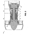
- FIG. 2 is a schematic diagram depicting an exemplary embodiment of a gas turbine engine, in which an embodiment of a hydrostatic face seal with integrated back-up seal can be used.
- engine 100 is configured as a turbofan that incorporates a fan 102, a compressor section 104, a combustion section 106 and a turbine section 108.
- FIG. 2 is configured as a turbofan, there is no intention to limit the concepts described herein to use with turbofans, as various other configurations of gas turbine engines can be used.
- Engine 100 is a dual spool engine that includes a high-pressure turbine 110 interconnected with a high-pressure compressor 112 via a shaft 114, and a low-pressure turbine 120 interconnected with a low-pressure compressor 122 via a shaft 124. It should also be noted that although various embodiments are described as incorporating hydrostatic face seals in low-pressure turbines, such seals are not limited to use with low-pressure turbines.
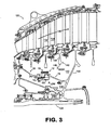
- low-pressure turbine 120 defines a primary gas flow path 130 along which multiple rotating blades (e.g., blade 132) and stationary vanes (e.g., vane 134) are located.
- the blades are mounted to turbine disks, the respective webs and bores of which extend into a high-pressure cavity 140.
- disk 142 includes a web 144 and a bore 146, each of which extends into cavity 140.
- a relatively lower-pressure cavity 148 is oriented between high-pressure cavity 140 and turbine hub 150, with a seal assembly 10 (described in detail before with respect to FIG. 1 ) being provided to maintain a pressure differential between the high-pressure cavity and the lower-pressure cavity.
- Seal assembly 10 incorporates a hydrostatic face seal 12 and a back-up seal 14 that are provided by a stator assembly 16 and a rotor assembly 18.
- the stator assembly is mounted to a non-rotating structure of the turbine, whereas the rotor assembly is mounted to a rotating structure.
- the rotor assembly is mounted to the low-pressure turbine hub 150.
- an intermediate-pressure cavity 151 is defined between hydrostatic face seal 12 and back-up seal 14.
- seal assembly 10 is provided as a removable assembly, the location of which can be adjusted axially and radially. As such, thrust balance trimming of engine 100 can be at least partially accommodated by altering the position of the seal assembly to adjust the volume of cavities 140 and 148
- the seal face intermittently contacts the seal runner.
- contact between the seal face and the seal runner can occur during sub-idle conditions and/or during transient conditions. That is, contact between the seal face and the seal runner is maintained until gas pressure in the high-pressure cavity is adequate to overcome the biasing force, thereby separating the seal face from the seal runner.
- the seal face and the seal runner should not contact each other.
- a material containing carbon can be used as a seal face material. It should be noted, however, that carbon can fracture or otherwise be damaged due to unintended contact (e.g., excessively forceful contact) between the seal face and the seal runner as may be caused by severe pressure fluctuations and/or vibrations, for example. It should also be noted that carbon may be susceptible to deterioration at higher temperatures. Therefore, carbon should be used in locations where predicted temperatures are not excessive such as in the low-pressure turbine. By way of example, use of such a material may not be appropriate, in some embodiments, in a high-pressure turbine.
- a nominal pressure differential exists between intermediate-pressure cavity 151 and lower-pressure cavity 148. That is, the pressure differential between the high-pressure cavity and the lower-pressure cavity is maintained, at least primarily, across the hydrostatic face seal 12.
- a failure mode of operation i.e., the hydrostatic seal fails
- the pressure of the high-pressure cavity 140 is depleted to a level lower than during the normal mode of operation but higher than that of intermediate cavity 151 during normal operation.
- the increase in pressure differential across the back-up seal 14 is due to the increased flow rate imposed on the back-up seal during failure of the primary seal.
- pressure in intermediate cavity 151 increases and a corresponding pressure differential is maintained, at least primarily, across the back-up seal 14.
Description
- The disclosure generally relates to gas turbine engines.
- A gas turbine engine typically maintains pressure differentials between various components during operation. These pressure differentials are commonly maintained by various configurations of seals. In this regard, labyrinth seals oftentimes are used in gas turbine engines. As is known, labyrinth seals tend to deteriorate over time. By way of example, a labyrinth seal can deteriorate due to rub interactions from thermal and mechanical growths, assembly tolerances, engine loads and maneuver deflections. Unfortunately, such deterioration can cause increased flow consumption resulting in increased parasitic losses and thermodynamic cycle loss.
-
GB 1 174 207 - Gas turbine engine systems involving hydrostatic face seals with integrated back-up seals are provided. In this regard, an embodiment of a seal assembly for a gas turbine engine is disclosed in independent claim 1.
- An embodiment of a turbine assembly for a gas turbine engine is disclosed in dependent claim 6.
- Other systems, methods, features and/or advantages of this disclosure will be or may become apparent to one with skill in the art upon examination of the following drawings and detailed description. It is intended that all such additional systems, methods, features and/or advantages be included within this description and be within the scope of the present disclosure.
- Many aspects of the disclosure can be better understood with reference to the following drawings. The components in the drawings are not necessarily to scale. Moreover, in the drawings, like reference numerals designate corresponding parts throughout the several views.
-
FIG. 1 is a schematic diagram depicting an exemplary embodiment of a hydrostatic face seal with integrated back-up seal. -
FIG. 2 is a schematic diagram depicting an exemplary embodiment of a gas turbine engine. -
FIG. 3 is a schematic diagram depicting a portion of the low-pressure turbine ofFIG. 2 , showing detail of the embodiment of the hydrostatic face seal with integrated back-up seal ofFIG. 1 installed therein. - Gas turbine engine systems involving hydrostatic face seals with integrated back-up seals are provided, several exemplary embodiments of which will be described in detail. In this regard, hydrostatic face seals can be used at various locations of a gas turbine engine, such as in association with a low-pressure turbine. Notably, a hydrostatic seal is a seal that uses balanced opening and closing forces to maintain a desired separation between a seal face and a corresponding seal runner. Unanticipated pressure fluctuations and/or vibrations could cause undesired contact between the seal face and the corresponding seal runner that can cause damage to the seal, e.g., carbon fracture. To mitigate the potential consequence of a damaged hydrostatic face seal, a back-up seal can be provided that is integrated with one or more components forming the hydrostatic seal.
- An exemplary embodiment of a hydrostatic face seal with an integrated back-up seal (collectively referred to herein as a "seal assembly") is depicted schematically in
FIG. 1 . As shown inFIG. 1 ,seal assembly 10 incorporates ahydrostatic face seal 12 and a back-up seal 14 that are provided by astationary stator assembly 16 and a rotatingrotor assembly 18. In general, the stator assembly incorporates the seal face of the associated hydrostatic face seal, as well as one or more of the primary components of the back-up seal. In contrast, the rotor assembly incorporates the seal runner of the hydrostatic face seal and others of the primary components of the back-up seal. Notably, when the back-up seal is a labyrinth seal, the stator assembly carries either the honeycomb lands or the knife edges, whereas the rotor carries the corresponding feature of the seal. In the embodiment ofFIG. 1 , the stator assembly incorporates the honeycomb lands and the rotor assembly incorporates the knife edges as will be described in detail. - With respect to the stator assembly,
stator assembly 16 includes anarm 17 that extends from amounting bracket 19.Mounting bracket 19 facilitates attachment, removal and/or position adjustment of the stator assembly. Notably, other embodiments may not incorporate mounting brackets for ease of installation and/or removal. -
Stator assembly 16 incorporates acarrier 20 that carriesface seal 22, which is annular in shape.Face seal 22 includes aseal face 24, which is one of the seal-forming surfaces of the hydrostatic seal.Carrier 20 is axially translatable so thatseal face 24 can move, with the carrier, away from or toward (e.g., into contact with) a seal runner 26 (which is the other of the seal-forming components of the hydrostatic seal) ofrotor assembly 18. In this embodiment, ananti-rotation lock 28 is provided to prevent circumferential displacement and to assist in aligning the seal carrier to facilitate axial translation. - A
biasing member 30, which is provided as a spring in this embodiment, biases the seal face against the seal runner until overcome by gas pressure. In this regard, the biasing force of the biasing member can be selected to maintain a desired pressure differential between a high-pressure side (PHIGH) and a low-pressure side (PLOW) of the seal. Multiple biasing members may be spaced about the stator and carrier. Notably, apiston ring 32 is captured betweenopposing surfaces -
Surface 40 of the carrier mounts lands 42, 44 of the labyrinth-type back-upseal 14. The lands may be comprised of an abradable structure such as honeycomb. Correspondingknife edges - With respect to the rotor assembly,
rotor assembly 18 supports theseal runner 26, which is annular in shape. Specifically, the rotor assembly includes anarm 56 that extends from amounting bracket 58.Mounting bracket 58 facilitates attachment, removal and/or position adjustment of the rotor assembly. - The
knife edges annular extension 60 that extends from the arm of the rotor assembly. Thus,extension 60 assists in defining an intermediate-pressure cavity 62 that is located between the hydrostatic seal and the back-up seal. Note also thatextension 60 can assist in preventing debris (e.g., debris that may by attributable to unintended damage of the hydrostatic seal) from passing beyond the back-up seal. - In a normal mode of operation (i.e., when the hydrostatic face seal is properly seated), the desired pressure differential is maintained, at least primarily, across the
hydrostatic face seal 12. However, in a failure mode of operation (i.e., when the hydrostatic face seal fails due to unintended circumstances), a corresponding pressure differential is maintained, at least primarily, across the back-upseal 14. Thus, in the failure mode of operation, intermediate-pressure cavity 62 typically exhibits PHIGH. -
FIG. 2 is a schematic diagram depicting an exemplary embodiment of a gas turbine engine, in which an embodiment of a hydrostatic face seal with integrated back-up seal can be used. As shown inFIG. 2 ,engine 100 is configured as a turbofan that incorporates afan 102, acompressor section 104, acombustion section 106 and aturbine section 108. Although the embodiment ofFIG. 2 is configured as a turbofan, there is no intention to limit the concepts described herein to use with turbofans, as various other configurations of gas turbine engines can be used. -
Engine 100 is a dual spool engine that includes a high-pressure turbine 110 interconnected with a high-pressure compressor 112 via ashaft 114, and a low-pressure turbine 120 interconnected with a low-pressure compressor 122 via ashaft 124. It should also be noted that although various embodiments are described as incorporating hydrostatic face seals in low-pressure turbines, such seals are not limited to use with low-pressure turbines. - As shown in
FIG. 3 , low-pressure turbine 120 defines a primarygas flow path 130 along which multiple rotating blades (e.g., blade 132) and stationary vanes (e.g., vane 134) are located. In this embodiment, the blades are mounted to turbine disks, the respective webs and bores of which extend into a high-pressure cavity 140. For instance,disk 142 includes aweb 144 and abore 146, each of which extends intocavity 140. - A relatively lower-
pressure cavity 148 is oriented between high-pressure cavity 140 andturbine hub 150, with a seal assembly 10 (described in detail before with respect toFIG. 1 ) being provided to maintain a pressure differential between the high-pressure cavity and the lower-pressure cavity.Seal assembly 10 incorporates ahydrostatic face seal 12 and a back-up seal 14 that are provided by astator assembly 16 and arotor assembly 18. Notably, the stator assembly is mounted to a non-rotating structure of the turbine, whereas the rotor assembly is mounted to a rotating structure. In the implementation ofFIG. 3 , the rotor assembly is mounted to the low-pressure turbine hub 150. Additionally, an intermediate-pressure cavity 151 is defined betweenhydrostatic face seal 12 and back-up seal 14. - It should be noted that
seal assembly 10 is provided as a removable assembly, the location of which can be adjusted axially and radially. As such, thrust balance trimming ofengine 100 can be at least partially accommodated by altering the position of the seal assembly to adjust the volume ofcavities - In operation, the seal face intermittently contacts the seal runner. By way of example, contact between the seal face and the seal runner can occur during sub-idle conditions and/or during transient conditions. That is, contact between the seal face and the seal runner is maintained until gas pressure in the high-pressure cavity is adequate to overcome the biasing force, thereby separating the seal face from the seal runner. During normal operating conditions, however, the seal face and the seal runner should not contact each other.
- Since the embodiments described herein are configured as lift-off seals (i.e., at least intermittent contact is expected), materials forming the surfaces that will contact each other are selected, at least in part, for their durability. In this regard, a material containing carbon can be used as a seal face material. It should be noted, however, that carbon can fracture or otherwise be damaged due to unintended contact (e.g., excessively forceful contact) between the seal face and the seal runner as may be caused by severe pressure fluctuations and/or vibrations, for example. It should also be noted that carbon may be susceptible to deterioration at higher temperatures. Therefore, carbon should be used in locations where predicted temperatures are not excessive such as in the low-pressure turbine. By way of example, use of such a material may not be appropriate, in some embodiments, in a high-pressure turbine.
- In a normal mode of operation (i.e., when the hydrostatic seal is properly functioning), a nominal pressure differential exists between intermediate-
pressure cavity 151 and lower-pressure cavity 148. That is, the pressure differential between the high-pressure cavity and the lower-pressure cavity is maintained, at least primarily, across thehydrostatic face seal 12. However, in a failure mode of operation (i.e., the hydrostatic seal fails), the pressure of the high-pressure cavity 140 is depleted to a level lower than during the normal mode of operation but higher than that ofintermediate cavity 151 during normal operation. The increase in pressure differential across the back-up seal 14 is due to the increased flow rate imposed on the back-up seal during failure of the primary seal. Thus, in the failure mode of operation, pressure inintermediate cavity 151 increases and a corresponding pressure differential is maintained, at least primarily, across the back-up seal 14. - It should be emphasized that the above-described embodiments are merely possible examples of implementations set forth for a clear understanding of the principles of this disclosure. Many variations and modifications may be made to the above-described embodiments without departing substantially from the principles of the disclosure. By way of example, although the embodiments described herein are configured as lift-off seals, other types of seals can be used. All such modifications and variations are intended to be included herein within the scope of this disclosure and protected by the accompanying claims.
Claims (8)
- A seal assembly (10) for a gas turbine engine comprising:a stator assembly (16) and a rotor assembly (18) configured to operatively engage each other to form a first seal (12) and a second seal (14), wherein the stator assembly (16) has a carrier (20), a face seal (22) being mounted to the carrier (20) such that the carrier (20) positions the seal face (24) with respect to the seal runner (26);the first seal (12) being provided by a hydrostatic seal having a seal face (24) and a seal runner (26), wherein the seal runner (26) is a portion of the rotor assembly (18);
andthe second seal (14) being provided by a labyrinth seal such that responsive to a failure of the first seal (12), the back-up seal (14) maintains at least a portion of a pressure differential established by the first seal (12) prior to the failure;wherein the labyrinth seal (14) has a land (42) and a knife edge (52), the knife edge (52) being operative to interact with the land (42) to form the second seal (14), the land (42) being supported by the stator assembly (16) and the knife edge (52) being supported by the rotor assembly (18), characterised in that the seal assembly has an annular extension (60) that extends from an arm of the rotor assembly, which annular extension (60) assists in defining an intermediate-pressure cavity (62) that is located between the first seal (12) and the second seal (14). - The assembly of claim 1, wherein the carrier (20) is operative to move the seal face (24) in the axial direction of the gas turbine engine.
- The assembly of claim 1 or claim 2, wherein each of the stator assembly (16) and the rotor assembly (18) has a mounting bracket (17, 56) operative to removably mount the stator assembly (16) and the rotor assembly (18), respectively, within the gas turbine engine.
- The assembly of any preceding claim, wherein the hydrostatic seal (12) is a lift-off seal, with the seal face (24) being biased to a contact position in which the seal face (24) contacts the seal runner (26).
- The assembly of claim 4, wherein the stator assembly (16) has a biasing member (30) operative to bias the seal face (24) to the contact position.
- A turbine assembly for a gas turbine engine, comprising a turbine (120) having a seal assembly as claimed in claim 1.
- The turbine assembly of claim 6, wherein the turbine (120) is a low-pressure turbine.
- The assembly of any preceding claim, wherein at least a portion of the seal face (24) configured to contact the seal runner (26) is formed of a material comprising carbon.
Applications Claiming Priority (3)
| Application Number | Priority Date | Filing Date | Title |
|---|---|---|---|
| US11/840,636 US8109717B2 (en) | 2007-08-17 | 2007-08-17 | Gas turbine engine systems involving hydrostatic face seals with integrated back-up seals |
| US11/840,645 US8109716B2 (en) | 2007-08-17 | 2007-08-17 | Gas turbine engine systems involving hydrostatic face seals with anti-fouling provisioning |
| US11/841,124 US8105021B2 (en) | 2007-08-20 | 2007-08-20 | Gas turbine engine systems involving hydrostatic face seals with integrated back-up seals |
Publications (3)
| Publication Number | Publication Date |
|---|---|
| EP2025876A2 EP2025876A2 (en) | 2009-02-18 |
| EP2025876A3 EP2025876A3 (en) | 2011-05-18 |
| EP2025876B1 true EP2025876B1 (en) | 2012-05-23 |
Family
ID=39832369
Family Applications (1)
| Application Number | Title | Priority Date | Filing Date |
|---|---|---|---|
| EP20080252724 Active EP2025876B1 (en) | 2007-08-17 | 2008-08-18 | Hydrostatic seal and back-up seal of a gas turbine engine and corresponding turbine assembly |
Country Status (1)
| Country | Link |
|---|---|
| EP (1) | EP2025876B1 (en) |
Families Citing this family (1)
| Publication number | Priority date | Publication date | Assignee | Title |
|---|---|---|---|---|
| US11053797B2 (en) * | 2017-01-23 | 2021-07-06 | General Electric Company | Rotor thrust balanced turbine engine |
Family Cites Families (8)
| Publication number | Priority date | Publication date | Assignee | Title |
|---|---|---|---|---|
| US2545916A (en) * | 1947-08-19 | 1951-03-20 | Armstrong Siddeley Motors Ltd | Labyrinth packings, particularly for use in internal-combustion turbines |
| GB1174207A (en) * | 1968-05-30 | 1969-12-17 | Rolls Royce | Improvements in or relating to fluid flow machines |
| US4103899A (en) * | 1975-10-01 | 1978-08-01 | United Technologies Corporation | Rotary seal with pressurized air directed at fluid approaching the seal |
| US6676369B2 (en) * | 2002-03-26 | 2004-01-13 | General Electric Company | Aspirating face seal with axially extending seal teeth |
| KR100711114B1 (en) * | 2004-07-02 | 2007-04-24 | 니폰 필라고교 가부시키가이샤 | Mechanical Seal |
| JP4336286B2 (en) * | 2004-10-08 | 2009-09-30 | 日本ピラー工業株式会社 | Hydrostatic non-contact gas seal |
| US20070253809A1 (en) * | 2006-05-01 | 2007-11-01 | General Electric Company | Methods and apparatus for assembling gas turbine engines |
| US20080018054A1 (en) * | 2006-07-20 | 2008-01-24 | General Electric Company | Aspirating labyrinth seal |
-
2008
- 2008-08-18 EP EP20080252724 patent/EP2025876B1/en active Active
Also Published As
| Publication number | Publication date |
|---|---|
| EP2025876A3 (en) | 2011-05-18 |
| EP2025876A2 (en) | 2009-02-18 |
Similar Documents
| Publication | Publication Date | Title |
|---|---|---|
| US8105021B2 (en) | Gas turbine engine systems involving hydrostatic face seals with integrated back-up seals | |
| EP2025875B1 (en) | Hydrostatic seal and back-up seal of a gas turbine engine | |
| US8167545B2 (en) | Self-balancing face seals and gas turbine engine systems involving such seals | |
| EP2025874B1 (en) | Hydrostatic seal of a gas turbine engine and corresponding gas turbine engine | |
| US7797941B2 (en) | Gas turbine engine systems involving hydrostatic face seals | |
| US20090051120A1 (en) | Gas Turbine Engine Systems Involving Hydrostatic Face Seals | |
| US7909335B2 (en) | Retractable compliant plate seals | |
| US8540479B2 (en) | Active retractable seal for turbo machinery and related method | |
| US8939715B2 (en) | Active tip clearance control for shrouded gas turbine blades and related method | |
| JP5060035B2 (en) | Seal assembly and manufacturing method thereof | |
| US8152450B1 (en) | Floating air seal for a turbine | |
| EP3002487B1 (en) | Sealing system | |
| US20100078893A1 (en) | Active retractable seal for turbomachinery and related method | |
| JP2007120501A (en) | Interstage seal, turbine blade, and interface seal between cooled rotor and stator of gas turbine engine | |
| CN103216277A (en) | Turbomachine with an angled abradable interstage seal and corresponding method of reducing a seal gap | |
| CA2769217A1 (en) | Outer shell sector for a bladed ring for an aircraft turbomachine stator, including vibration damping shims | |
| EP1505260A2 (en) | Sealing arrangement in turbomachinery | |
| EP2233700B1 (en) | Self balancing face seals and gas turbine engine systems involving such seals | |
| WO2015115400A1 (en) | Shaft seal device and rotary machine | |
| CA2591249A1 (en) | Aspirating labyrinth seal | |
| US9829007B2 (en) | Turbine sealing system | |
| EP2020542A1 (en) | Seal assembly | |
| EP2025876B1 (en) | Hydrostatic seal and back-up seal of a gas turbine engine and corresponding turbine assembly | |
| EP2025877A2 (en) | Hydrostatic seal of a gas turbine engine and corresponding turbine assembly | |
| US20230106380A1 (en) | Seal assembly for a rotary machine |
Legal Events
| Date | Code | Title | Description |
|---|---|---|---|
| PUAI | Public reference made under article 153(3) epc to a published international application that has entered the european phase |
Free format text: ORIGINAL CODE: 0009012 |
|
| AK | Designated contracting states |
Kind code of ref document: A2 Designated state(s): AT BE BG CH CY CZ DE DK EE ES FI FR GB GR HR HU IE IS IT LI LT LU LV MC MT NL NO PL PT RO SE SI SK TR |
|
| AX | Request for extension of the european patent |
Extension state: AL BA MK RS |
|
| PUAL | Search report despatched |
Free format text: ORIGINAL CODE: 0009013 |
|
| AK | Designated contracting states |
Kind code of ref document: A3 Designated state(s): AT BE BG CH CY CZ DE DK EE ES FI FR GB GR HR HU IE IS IT LI LT LU LV MC MT NL NO PL PT RO SE SI SK TR |
|
| AX | Request for extension of the european patent |
Extension state: AL BA MK RS |
|
| RIC1 | Information provided on ipc code assigned before grant |
Ipc: F02C 7/28 20060101ALI20110412BHEP Ipc: F16J 15/34 20060101ALI20110412BHEP Ipc: F16J 15/44 20060101ALI20110412BHEP Ipc: F01D 11/04 20060101ALI20110412BHEP Ipc: F01D 11/02 20060101AFI20110412BHEP |
|
| 17P | Request for examination filed |
Effective date: 20111116 |
|
| REG | Reference to a national code |
Ref country code: DE Ref legal event code: R079 Ref document number: 602008015831 Country of ref document: DE Free format text: PREVIOUS MAIN CLASS: F01D0011000000 Ipc: F01D0011020000 |
|
| AKX | Designation fees paid |
Designated state(s): DE GB |
|
| GRAP | Despatch of communication of intention to grant a patent |
Free format text: ORIGINAL CODE: EPIDOSNIGR1 |
|
| RIC1 | Information provided on ipc code assigned before grant |
Ipc: F01D 11/02 20060101AFI20120118BHEP Ipc: F16J 15/34 20060101ALI20120118BHEP Ipc: F02C 7/28 20060101ALI20120118BHEP Ipc: F16J 15/44 20060101ALI20120118BHEP Ipc: F01D 11/04 20060101ALI20120118BHEP |
|
| GRAS | Grant fee paid |
Free format text: ORIGINAL CODE: EPIDOSNIGR3 |
|
| GRAA | (expected) grant |
Free format text: ORIGINAL CODE: 0009210 |
|
| AK | Designated contracting states |
Kind code of ref document: B1 Designated state(s): DE GB |
|
| REG | Reference to a national code |
Ref country code: GB Ref legal event code: FG4D |
|
| REG | Reference to a national code |
Ref country code: DE Ref legal event code: R096 Ref document number: 602008015831 Country of ref document: DE Effective date: 20120726 |
|
| PLBE | No opposition filed within time limit |
Free format text: ORIGINAL CODE: 0009261 |
|
| STAA | Information on the status of an ep patent application or granted ep patent |
Free format text: STATUS: NO OPPOSITION FILED WITHIN TIME LIMIT |
|
| 26N | No opposition filed |
Effective date: 20130226 |
|
| REG | Reference to a national code |
Ref country code: DE Ref legal event code: R097 Ref document number: 602008015831 Country of ref document: DE Effective date: 20130226 |
|
| REG | Reference to a national code |
Ref country code: DE Ref legal event code: R082 Ref document number: 602008015831 Country of ref document: DE Representative=s name: SCHMITT-NILSON SCHRAUD WAIBEL WOHLFROM PATENTA, DE |
|
| REG | Reference to a national code |
Ref country code: DE Ref legal event code: R082 Ref document number: 602008015831 Country of ref document: DE Representative=s name: SCHMITT-NILSON SCHRAUD WAIBEL WOHLFROM PATENTA, DE Ref country code: DE Ref legal event code: R081 Ref document number: 602008015831 Country of ref document: DE Owner name: UNITED TECHNOLOGIES CORP. (N.D.GES.D. STAATES , US Free format text: FORMER OWNER: UNITED TECHNOLOGIES CORPORATION, HARTFORD, CONN., US |
|
| REG | Reference to a national code |
Ref country code: DE Ref legal event code: R081 Ref document number: 602008015831 Country of ref document: DE Owner name: RAYTHEON TECHNOLOGIES CORPORATION (N.D.GES.D.S, US Free format text: FORMER OWNER: UNITED TECHNOLOGIES CORP. (N.D.GES.D. STAATES DELAWARE), FARMINGTON, CONN., US |
|
| P01 | Opt-out of the competence of the unified patent court (upc) registered |
Effective date: 20230519 |
|
| PGFP | Annual fee paid to national office [announced via postgrant information from national office to epo] |
Ref country code: GB Payment date: 20230720 Year of fee payment: 16 |
|
| PGFP | Annual fee paid to national office [announced via postgrant information from national office to epo] |
Ref country code: DE Payment date: 20230720 Year of fee payment: 16 |