EP2233592B1 - A taphole drill - Google Patents
A taphole drill Download PDFInfo
- Publication number
- EP2233592B1 EP2233592B1 EP10150985.9A EP10150985A EP2233592B1 EP 2233592 B1 EP2233592 B1 EP 2233592B1 EP 10150985 A EP10150985 A EP 10150985A EP 2233592 B1 EP2233592 B1 EP 2233592B1
- Authority
- EP
- European Patent Office
- Prior art keywords
- pivot
- drill
- taphole
- arm
- primary
- Prior art date
- Legal status (The legal status is an assumption and is not a legal conclusion. Google has not performed a legal analysis and makes no representation as to the accuracy of the status listed.)
- Active
Links
- 238000005553 drilling Methods 0.000 claims description 8
- 230000009977 dual effect Effects 0.000 claims description 7
- 239000002184 metal Substances 0.000 description 4
- 229910052751 metal Inorganic materials 0.000 description 4
- XEEYBQQBJWHFJM-UHFFFAOYSA-N Iron Chemical compound [Fe] XEEYBQQBJWHFJM-UHFFFAOYSA-N 0.000 description 2
- 239000004927 clay Substances 0.000 description 1
- 229910052742 iron Inorganic materials 0.000 description 1
- 238000009527 percussion Methods 0.000 description 1
- 239000007787 solid Substances 0.000 description 1
Images


Classifications
-
- C—CHEMISTRY; METALLURGY
- C21—METALLURGY OF IRON
- C21B—MANUFACTURE OF IRON OR STEEL
- C21B7/00—Blast furnaces
- C21B7/12—Opening or sealing the tap holes
-
- F—MECHANICAL ENGINEERING; LIGHTING; HEATING; WEAPONS; BLASTING
- F27—FURNACES; KILNS; OVENS; RETORTS
- F27D—DETAILS OR ACCESSORIES OF FURNACES, KILNS, OVENS, OR RETORTS, IN SO FAR AS THEY ARE OF KINDS OCCURRING IN MORE THAN ONE KIND OF FURNACE
- F27D3/00—Charging; Discharging; Manipulation of charge
- F27D3/15—Tapping equipment; Equipment for removing or retaining slag
- F27D3/1509—Tapping equipment
- F27D3/1527—Taphole forming equipment, e.g. boring machines, piercing tools
Landscapes
- Engineering & Computer Science (AREA)
- Mechanical Engineering (AREA)
- General Engineering & Computer Science (AREA)
- Chemical & Material Sciences (AREA)
- Manufacturing & Machinery (AREA)
- Materials Engineering (AREA)
- Metallurgy (AREA)
- Organic Chemistry (AREA)
- Blast Furnaces (AREA)
- Earth Drilling (AREA)
- Surgical Instruments (AREA)
Description
- This invention relates to a taphole drill for opening a blast furnace taphole.
- At the lower region of a blast furnace used in iron production, a taphole is provided which is sealed and un-sealed as the furnace is operated to release molten metal from the furnace. The hole is sealed with clay which hardens with the heat of the furnace and this has to be drilled using a large pneumatic or hydraulically powered rotary percussion drill when sufficient metal has gathered at the furnace bottom.
- An example of a blast furnace taphole drill is described in
US6086816 .KR2003-0048813A US6251338 describes a segmented control arm system for a drilling apparatus. It will be appreciated that blast furnaces are large items of equipment (a typical blast furnace might produce tens of thousands of tonnes of metal per week). The furnace is housed in a correspondingly large building or complex of buildings. However, not withstanding this, the floor space about a furnace is often constrained as it will include troughs and runners for receiving the molten metal when the furnace is tapped. - A taphole drill is itself a very large item of equipment which requires a substantial support structure which also allows movement of the drill by a foundry worker from a "parked" position to a drilling position where the drill bit is centred on the taphole. There are two current arrangements for mounting a taphole drill. In a first arrangement, a slewing jib arm is provided having a parallel linkage connected to a control arm. The jib slews (rotates) about a primary pivot. A second arrangement does not have a control arm but a single linkage to a drill guide. Both arrangements occupy a large area of the foundry workshop floor and hamper access to the taphole.
- The present invention arose from a desire to provide a taphole drill which permits good access to the taphole when the drill is placed in a stowed (parked) position.
- According to the invention there is provided a taphole drill comprising a primary pivot to which a jib arm is mounted at a first end which jib arm divided into a first and a second part at a pivot point, a drill guide fixed to an end of the first part; a control arm link connect to the first part of the jib arm at a position intermediate the pivot point and the end to which the drill guide is fixed wherein the other end of the control arm is connected to a dual position pivot point which is moveable from a first pivot position when the drill is in a parked position to a second pivot position different to the first when the drill is in the drilling position.
- This arrangement is compact and allows good access to the taphole when the drill is in the parked position.
- Preferably, the first pivot position is located at a first distance from the primary pivot and the second pivot position is located at a second distance greater than the first distance from the primary pivot.
- Preferably, the control arm is pivotably connected to a link by a control arm pivot which link being connected to the primary pivot by a second pivot such that as the jib arm is rotated about the first pivot the link pivots about the second pivot to move the control arm pivot from the first pivot position to the second pivot position.
- Preferably, the primary pivot has a stop to limit the motion of the link and thus to set the second position.
- Preferably the link comprises a rear and a front wherein the front abuts a second stop to define the first pivot position and rear abuts the first stop to define the second position.
- A specific embodiment of the invention will now be described, by way of example only, with reference to the drawing in which:
-
Figure 1 shows a taphole drill in accordance with an embodiment of the invention; -
Figure 2 shows a pivot arrangement used in the taphole drill offigure 1 ; -
Figure 3 is a perspective view of a link used in the pivot arrangement; and -
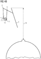
Figure 4 is an illustrative figure showing a slewing trajectory of the taphole drill. - As is shown in
figure 1 , a taphole drill 1 in accordance with the invention comprises a drill motor 2, adrill guide 3 and adrill bit shaft 4 fixed to the end of a jib arm 5. The jib arm 5 has ajib arm pivot 6 at an intermediate position. The arm may therefore be considered to be formed of afirst limb 5a and asecond limb 5b. Thelimb 5b extends a primary pivot 7 to which it is mounted to allow rotational movement thereabout. Thus the taphole drill 1 is able to be rotated or slewed about the primary pivot 7. - The taphole drill 1 also includes a
control arm 8 which is attached to thefirst limb 5a at a position intermediate thejib arm pivot 6 and the other end to which the drill motor 2 is mounted. Thecontrol arm 8 is fixed by means of apivot 9. The other end of thecontrol arm 8 is attached to alink 10 by means of a linkfirst pivot 11. Thelink 10 is attached to the primary pivot 7 by means of a linksecond pivot 12. This is more clearly shown infigure 2 . - The primary pivot 7 includes a
radial extension 13 welded to its surface which includes a hole through which a pivot pin for thepivot 12 is located. As is shown in the figure, as the taphole drill 1 is rotated clock-wise about the pivot 7, thelink 10 moves from a parked drill position shown in broken outline to the drilling position shown in solid outline. Both positions are defined by the link abutting respective shim stops 13a and 14 carried on the pivot surface. It will be seen that a radial distance A of thepivot 11 to the axis of the pivot 7 in the stowed or parked position is shorter than the radial distance B when thepivot 11 is in the drilling position. The link has the indicatedtrajectory 15 as movement about the pivot 7 occurs leading to the pivoting of thelink 10 about thepivot 12. - The
link 10 is shown in greater detail infigure 3 . It can be seen that it comprises an upper andlower plates central body 17. -
Figure 4 shows in a schematic way the taphole drill slew trajectory as movement occurs between the drill parked position offigure 4a , to an intermediate position offigure 4b and then to the drilling position offigure 4c . It will be seen that as the drill is slewed about the primary pivot 7 the distance between the primary pivot 7 topivot 11 is increased causing an extension in the radial distance C1 to C2 between the pivot 7 and thedrill guide 4. Movement in the opposite direction results in the arrangement folding in on itself to provide a more compact footprint than is possible with other prior art arrangements. - In
figure 4a it will be seen that when in the parked position there is a clearance labelled "T" between the closest part of the taphole drill (pivot 12) and thetaphole 20 offurnace 21. This clearance is larger that would be possible with prior art arrangements permitting good access to thetaphole 20. - In the mid-point position in
figure 4b , it will be seen that the rear of thedrill guide 4 is at its greatest backward extent at a distance B from the taphole. This is termed the "back-swing" and it is shorter than prior art arrangements.
Claims (5)
- A taphole drill (1) comprising a primary pivot (7) to which a jib arm (5) is mounted at a first end which jib arm divided into a first (5a) and a second (5b) part at a jib arm pivot point (6), a drill guide (3) fixed to an end of the first part (5a); a control arm (8) linked to the first part (5a) of the jib arm (5) at a position intermediate the jib arm pivot point (6) and the end to which the drill guide is fixed, and the other end of the control arm (8) being connected to a dual position pivot point (10) which is moveable from a first pivot position when the drill is in a parked position to a second pivot position different to the first when the drill is in the drilling position.
- A taphole drill as claimed in claim 1 wherein the first pivot position is located at a first distance (A) from the primary pivot (7) and the second pivot position is located at a second distance (B) greater than the first distance from the primary pivot.
- A taphole drill as claimed in claim 1 or 2 wherein the control arm (8) is pivotably connected to the dual position pivot point (10) by a control arm pivot (11) which dual position pivot point is connected to the primary pivot (7) by a second pivot (12) such that as the jib arm is rotated about the primary pivot (7) the dual position pivot point (10) pivots about the second pivot (12) to move the control arm pivot (11) from the first to the second pivot position.
- A taphole drill as claimed in claim 3 wherein the primary pivot (7) has a first stop (13a) to limit the motion of the dual position pivot point (10) and thus to set the second pivot position.
- A taphole drill as claimed in claim 4 wherein the dual position pivot point (10) comprises a rear and a front wherein the front abuts a second stop (14) to define the first pivot position and rear abuts the first stop (13a) to define the second pivot position.
Applications Claiming Priority (1)
| Application Number | Priority Date | Filing Date | Title |
|---|---|---|---|
| GB0905254A GB2468910B (en) | 2009-03-27 | 2009-03-27 | A taphole drill |
Publications (3)
| Publication Number | Publication Date |
|---|---|
| EP2233592A2 EP2233592A2 (en) | 2010-09-29 |
| EP2233592A3 EP2233592A3 (en) | 2011-02-16 |
| EP2233592B1 true EP2233592B1 (en) | 2018-05-30 |
Family
ID=40671798
Family Applications (1)
| Application Number | Title | Priority Date | Filing Date |
|---|---|---|---|
| EP10150985.9A Active EP2233592B1 (en) | 2009-03-27 | 2010-01-18 | A taphole drill |
Country Status (2)
| Country | Link |
|---|---|
| EP (1) | EP2233592B1 (en) |
| GB (1) | GB2468910B (en) |
Families Citing this family (1)
| Publication number | Priority date | Publication date | Assignee | Title |
|---|---|---|---|---|
| CN112432506A (en) * | 2020-11-25 | 2021-03-02 | 商都中建金马冶金化工有限公司 | A open stifled eye machine for hot stove in ore deposit |
Citations (2)
| Publication number | Priority date | Publication date | Assignee | Title |
|---|---|---|---|---|
| US4201373A (en) * | 1978-06-01 | 1980-05-06 | Paul Wurth-S.A. | Guiding and positioning mechanism for a plugging or drilling device |
| US6251338B1 (en) * | 1997-07-09 | 2001-06-26 | Paul Wurth, S.A. | Pivoting device with arm and control rod |
Family Cites Families (7)
| Publication number | Priority date | Publication date | Assignee | Title |
|---|---|---|---|---|
| GB1174536A (en) * | 1967-09-11 | 1969-12-17 | Dango & Dienenthal Kg | Apparatus for Opening and Closing Tap Holes of Shaft Furnaces |
| LU78209A1 (en) * | 1977-09-30 | 1978-01-23 | ||
| DE3044087A1 (en) * | 1980-11-24 | 1982-06-16 | Dango & Dienenthal Maschinenbau GmbH, 5900 Siegen | STITCH HOLE DRILL |
| DE19630078C2 (en) * | 1996-07-26 | 2003-03-27 | Dango & Dienenthal Maschbau | Lifting device for tap hole drilling machines |
| US6086816A (en) | 1997-05-08 | 2000-07-11 | Pohang Iron & Steel Co., Ltd. | Tap hole drilling machine for blast furnace, drill bit for use in tap hole drilling machine, and tap hole drilling method |
| LU90093B1 (en) * | 1997-07-16 | 1999-01-18 | Wurth Paul Sa | Swivel device with boom |
| KR100856278B1 (en) * | 2001-12-13 | 2008-09-03 | 주식회사 포스코 | A Tapping Apparatus For Tap Hole Of Blast Furnace |
-
2009
- 2009-03-27 GB GB0905254A patent/GB2468910B/en not_active Expired - Fee Related
-
2010
- 2010-01-18 EP EP10150985.9A patent/EP2233592B1/en active Active
Patent Citations (2)
| Publication number | Priority date | Publication date | Assignee | Title |
|---|---|---|---|---|
| US4201373A (en) * | 1978-06-01 | 1980-05-06 | Paul Wurth-S.A. | Guiding and positioning mechanism for a plugging or drilling device |
| US6251338B1 (en) * | 1997-07-09 | 2001-06-26 | Paul Wurth, S.A. | Pivoting device with arm and control rod |
Also Published As
| Publication number | Publication date |
|---|---|
| EP2233592A3 (en) | 2011-02-16 |
| GB2468910A (en) | 2010-09-29 |
| GB0905254D0 (en) | 2009-05-13 |
| EP2233592A2 (en) | 2010-09-29 |
| GB2468910B (en) | 2011-05-11 |
Similar Documents
| Publication | Publication Date | Title |
|---|---|---|
| US7905300B2 (en) | Drilling device and drilling method utilizing dual drives | |
| US20090223093A1 (en) | Support Arm for a Work Machine | |
| US20130300181A1 (en) | Demolition hammer arrangement for a remote-controlled working machine equipped with a manoeuvrable arm | |
| WO2005035882B1 (en) | Multi-function work machine | |
| US20170234085A1 (en) | Adjustable breakout wrench for a mining machine | |
| EP1920206B1 (en) | Handling device for elements of tapping runners | |
| EP2635409B1 (en) | Demolition hammer for a working machine equipped with a manoeuvrable arm | |
| EP2233592B1 (en) | A taphole drill | |
| CN100415432C (en) | Welding gun | |
| US3549141A (en) | Apparatus for opening and closing the tap holes of shaft furnaces | |
| CN107558928A (en) | A kind of boom device and drill jumbo | |
| CN216828634U (en) | Pouring system | |
| AU2021218210B2 (en) | Dipper handle | |
| CN212894791U (en) | Linkage type clamp mechanism for automatic drill rod replacing machine | |
| CN215548645U (en) | Multifunctional manipulator | |
| SK283126B6 (en) | Device for opening and closing of tap in metallurgical furnace | |
| CN109235518B (en) | Quick-change structure of engineering machinery tool head and arm | |
| CN216549345U (en) | Engineering vehicle | |
| JP3007276B2 (en) | Hole alignment system for taphole drilling machine | |
| CN204754812U (en) | Oil drilling equipment , anvil worker and cantilever crane device thereof | |
| CN201447486U (en) | Adjusting device of slideway drilling mechanism | |
| CN220887577U (en) | Dismounting device for blast furnace rock drill | |
| JPS636316Y2 (en) | ||
| KR20110070952A (en) | Excavator tool | |
| KR200333298Y1 (en) | Composition Apparatus for Tap Hole |
Legal Events
| Date | Code | Title | Description |
|---|---|---|---|
| PUAI | Public reference made under article 153(3) epc to a published international application that has entered the european phase |
Free format text: ORIGINAL CODE: 0009012 |
|
| AK | Designated contracting states |
Kind code of ref document: A2 Designated state(s): AT BE BG CH CY CZ DE DK EE ES FI FR GB GR HR HU IE IS IT LI LT LU LV MC MK MT NL NO PL PT RO SE SI SK SM TR |
|
| PUAL | Search report despatched |
Free format text: ORIGINAL CODE: 0009013 |
|
| AK | Designated contracting states |
Kind code of ref document: A3 Designated state(s): AT BE BG CH CY CZ DE DK EE ES FI FR GB GR HR HU IE IS IT LI LT LU LV MC MK MT NL NO PL PT RO SE SI SK SM TR |
|
| 17P | Request for examination filed |
Effective date: 20110816 |
|
| RAP1 | Party data changed (applicant data changed or rights of an application transferred) |
Owner name: SIEMENS PLC |
|
| RAP1 | Party data changed (applicant data changed or rights of an application transferred) |
Owner name: PRIMETALS TECHNOLOGIES, LIMITED |
|
| TPAC | Observations filed by third parties |
Free format text: ORIGINAL CODE: EPIDOSNTIPA |
|
| STAA | Information on the status of an ep patent application or granted ep patent |
Free format text: STATUS: EXAMINATION IS IN PROGRESS |
|
| 17Q | First examination report despatched |
Effective date: 20161128 |
|
| GRAP | Despatch of communication of intention to grant a patent |
Free format text: ORIGINAL CODE: EPIDOSNIGR1 |
|
| STAA | Information on the status of an ep patent application or granted ep patent |
Free format text: STATUS: GRANT OF PATENT IS INTENDED |
|
| INTG | Intention to grant announced |
Effective date: 20180103 |
|
| GRAS | Grant fee paid |
Free format text: ORIGINAL CODE: EPIDOSNIGR3 |
|
| GRAA | (expected) grant |
Free format text: ORIGINAL CODE: 0009210 |
|
| STAA | Information on the status of an ep patent application or granted ep patent |
Free format text: STATUS: THE PATENT HAS BEEN GRANTED |
|
| AK | Designated contracting states |
Kind code of ref document: B1 Designated state(s): AT BE BG CH CY CZ DE DK EE ES FI FR GB GR HR HU IE IS IT LI LT LU LV MC MK MT NL NO PL PT RO SE SI SK SM TR |
|
| REG | Reference to a national code |
Ref country code: GB Ref legal event code: FG4D |
|
| REG | Reference to a national code |
Ref country code: CH Ref legal event code: EP |
|
| REG | Reference to a national code |
Ref country code: AT Ref legal event code: REF Ref document number: 1003673 Country of ref document: AT Kind code of ref document: T Effective date: 20180615 |
|
| REG | Reference to a national code |
Ref country code: IE Ref legal event code: FG4D |
|
| REG | Reference to a national code |
Ref country code: DE Ref legal event code: R096 Ref document number: 602010050860 Country of ref document: DE |
|
| REG | Reference to a national code |
Ref country code: NL Ref legal event code: MP Effective date: 20180530 |
|
| REG | Reference to a national code |
Ref country code: LT Ref legal event code: MG4D |
|
| PG25 | Lapsed in a contracting state [announced via postgrant information from national office to epo] |
Ref country code: SE Free format text: LAPSE BECAUSE OF FAILURE TO SUBMIT A TRANSLATION OF THE DESCRIPTION OR TO PAY THE FEE WITHIN THE PRESCRIBED TIME-LIMIT Effective date: 20180530 Ref country code: ES Free format text: LAPSE BECAUSE OF FAILURE TO SUBMIT A TRANSLATION OF THE DESCRIPTION OR TO PAY THE FEE WITHIN THE PRESCRIBED TIME-LIMIT Effective date: 20180530 Ref country code: LT Free format text: LAPSE BECAUSE OF FAILURE TO SUBMIT A TRANSLATION OF THE DESCRIPTION OR TO PAY THE FEE WITHIN THE PRESCRIBED TIME-LIMIT Effective date: 20180530 Ref country code: NO Free format text: LAPSE BECAUSE OF FAILURE TO SUBMIT A TRANSLATION OF THE DESCRIPTION OR TO PAY THE FEE WITHIN THE PRESCRIBED TIME-LIMIT Effective date: 20180830 Ref country code: FI Free format text: LAPSE BECAUSE OF FAILURE TO SUBMIT A TRANSLATION OF THE DESCRIPTION OR TO PAY THE FEE WITHIN THE PRESCRIBED TIME-LIMIT Effective date: 20180530 Ref country code: BG Free format text: LAPSE BECAUSE OF FAILURE TO SUBMIT A TRANSLATION OF THE DESCRIPTION OR TO PAY THE FEE WITHIN THE PRESCRIBED TIME-LIMIT Effective date: 20180830 Ref country code: CY Free format text: LAPSE BECAUSE OF FAILURE TO SUBMIT A TRANSLATION OF THE DESCRIPTION OR TO PAY THE FEE WITHIN THE PRESCRIBED TIME-LIMIT Effective date: 20180530 |
|
| PG25 | Lapsed in a contracting state [announced via postgrant information from national office to epo] |
Ref country code: LV Free format text: LAPSE BECAUSE OF FAILURE TO SUBMIT A TRANSLATION OF THE DESCRIPTION OR TO PAY THE FEE WITHIN THE PRESCRIBED TIME-LIMIT Effective date: 20180530 Ref country code: HR Free format text: LAPSE BECAUSE OF FAILURE TO SUBMIT A TRANSLATION OF THE DESCRIPTION OR TO PAY THE FEE WITHIN THE PRESCRIBED TIME-LIMIT Effective date: 20180530 Ref country code: GR Free format text: LAPSE BECAUSE OF FAILURE TO SUBMIT A TRANSLATION OF THE DESCRIPTION OR TO PAY THE FEE WITHIN THE PRESCRIBED TIME-LIMIT Effective date: 20180831 |
|
| REG | Reference to a national code |
Ref country code: AT Ref legal event code: MK05 Ref document number: 1003673 Country of ref document: AT Kind code of ref document: T Effective date: 20180530 |
|
| PG25 | Lapsed in a contracting state [announced via postgrant information from national office to epo] |
Ref country code: NL Free format text: LAPSE BECAUSE OF FAILURE TO SUBMIT A TRANSLATION OF THE DESCRIPTION OR TO PAY THE FEE WITHIN THE PRESCRIBED TIME-LIMIT Effective date: 20180530 |
|
| PG25 | Lapsed in a contracting state [announced via postgrant information from national office to epo] |
Ref country code: PL Free format text: LAPSE BECAUSE OF FAILURE TO SUBMIT A TRANSLATION OF THE DESCRIPTION OR TO PAY THE FEE WITHIN THE PRESCRIBED TIME-LIMIT Effective date: 20180530 Ref country code: EE Free format text: LAPSE BECAUSE OF FAILURE TO SUBMIT A TRANSLATION OF THE DESCRIPTION OR TO PAY THE FEE WITHIN THE PRESCRIBED TIME-LIMIT Effective date: 20180530 Ref country code: AT Free format text: LAPSE BECAUSE OF FAILURE TO SUBMIT A TRANSLATION OF THE DESCRIPTION OR TO PAY THE FEE WITHIN THE PRESCRIBED TIME-LIMIT Effective date: 20180530 Ref country code: DK Free format text: LAPSE BECAUSE OF FAILURE TO SUBMIT A TRANSLATION OF THE DESCRIPTION OR TO PAY THE FEE WITHIN THE PRESCRIBED TIME-LIMIT Effective date: 20180530 Ref country code: RO Free format text: LAPSE BECAUSE OF FAILURE TO SUBMIT A TRANSLATION OF THE DESCRIPTION OR TO PAY THE FEE WITHIN THE PRESCRIBED TIME-LIMIT Effective date: 20180530 Ref country code: CZ Free format text: LAPSE BECAUSE OF FAILURE TO SUBMIT A TRANSLATION OF THE DESCRIPTION OR TO PAY THE FEE WITHIN THE PRESCRIBED TIME-LIMIT Effective date: 20180530 Ref country code: SK Free format text: LAPSE BECAUSE OF FAILURE TO SUBMIT A TRANSLATION OF THE DESCRIPTION OR TO PAY THE FEE WITHIN THE PRESCRIBED TIME-LIMIT Effective date: 20180530 |
|
| PG25 | Lapsed in a contracting state [announced via postgrant information from national office to epo] |
Ref country code: IT Free format text: LAPSE BECAUSE OF FAILURE TO SUBMIT A TRANSLATION OF THE DESCRIPTION OR TO PAY THE FEE WITHIN THE PRESCRIBED TIME-LIMIT Effective date: 20180530 Ref country code: SM Free format text: LAPSE BECAUSE OF FAILURE TO SUBMIT A TRANSLATION OF THE DESCRIPTION OR TO PAY THE FEE WITHIN THE PRESCRIBED TIME-LIMIT Effective date: 20180530 |
|
| REG | Reference to a national code |
Ref country code: DE Ref legal event code: R097 Ref document number: 602010050860 Country of ref document: DE |
|
| PLBE | No opposition filed within time limit |
Free format text: ORIGINAL CODE: 0009261 |
|
| STAA | Information on the status of an ep patent application or granted ep patent |
Free format text: STATUS: NO OPPOSITION FILED WITHIN TIME LIMIT |
|
| 26N | No opposition filed |
Effective date: 20190301 |
|
| PG25 | Lapsed in a contracting state [announced via postgrant information from national office to epo] |
Ref country code: SI Free format text: LAPSE BECAUSE OF FAILURE TO SUBMIT A TRANSLATION OF THE DESCRIPTION OR TO PAY THE FEE WITHIN THE PRESCRIBED TIME-LIMIT Effective date: 20180530 |
|
| REG | Reference to a national code |
Ref country code: DE Ref legal event code: R119 Ref document number: 602010050860 Country of ref document: DE |
|
| PG25 | Lapsed in a contracting state [announced via postgrant information from national office to epo] |
Ref country code: MC Free format text: LAPSE BECAUSE OF FAILURE TO SUBMIT A TRANSLATION OF THE DESCRIPTION OR TO PAY THE FEE WITHIN THE PRESCRIBED TIME-LIMIT Effective date: 20180530 |
|
| REG | Reference to a national code |
Ref country code: CH Ref legal event code: PL |
|
| PG25 | Lapsed in a contracting state [announced via postgrant information from national office to epo] |
Ref country code: LU Free format text: LAPSE BECAUSE OF NON-PAYMENT OF DUE FEES Effective date: 20190118 |
|
| REG | Reference to a national code |
Ref country code: BE Ref legal event code: MM Effective date: 20190131 |
|
| REG | Reference to a national code |
Ref country code: IE Ref legal event code: MM4A |
|
| PG25 | Lapsed in a contracting state [announced via postgrant information from national office to epo] |
Ref country code: DE Free format text: LAPSE BECAUSE OF NON-PAYMENT OF DUE FEES Effective date: 20190801 Ref country code: FR Free format text: LAPSE BECAUSE OF NON-PAYMENT OF DUE FEES Effective date: 20190131 |
|
| PG25 | Lapsed in a contracting state [announced via postgrant information from national office to epo] |
Ref country code: BE Free format text: LAPSE BECAUSE OF NON-PAYMENT OF DUE FEES Effective date: 20190131 |
|
| PG25 | Lapsed in a contracting state [announced via postgrant information from national office to epo] |
Ref country code: CH Free format text: LAPSE BECAUSE OF NON-PAYMENT OF DUE FEES Effective date: 20190131 Ref country code: LI Free format text: LAPSE BECAUSE OF NON-PAYMENT OF DUE FEES Effective date: 20190131 |
|
| PG25 | Lapsed in a contracting state [announced via postgrant information from national office to epo] |
Ref country code: IE Free format text: LAPSE BECAUSE OF NON-PAYMENT OF DUE FEES Effective date: 20190118 |
|
| PG25 | Lapsed in a contracting state [announced via postgrant information from national office to epo] |
Ref country code: TR Free format text: LAPSE BECAUSE OF FAILURE TO SUBMIT A TRANSLATION OF THE DESCRIPTION OR TO PAY THE FEE WITHIN THE PRESCRIBED TIME-LIMIT Effective date: 20180530 |
|
| PG25 | Lapsed in a contracting state [announced via postgrant information from national office to epo] |
Ref country code: MT Free format text: LAPSE BECAUSE OF NON-PAYMENT OF DUE FEES Effective date: 20190118 Ref country code: PT Free format text: LAPSE BECAUSE OF FAILURE TO SUBMIT A TRANSLATION OF THE DESCRIPTION OR TO PAY THE FEE WITHIN THE PRESCRIBED TIME-LIMIT Effective date: 20181001 |
|
| PG25 | Lapsed in a contracting state [announced via postgrant information from national office to epo] |
Ref country code: IS Free format text: LAPSE BECAUSE OF FAILURE TO SUBMIT A TRANSLATION OF THE DESCRIPTION OR TO PAY THE FEE WITHIN THE PRESCRIBED TIME-LIMIT Effective date: 20180930 |
|
| PG25 | Lapsed in a contracting state [announced via postgrant information from national office to epo] |
Ref country code: HU Free format text: LAPSE BECAUSE OF FAILURE TO SUBMIT A TRANSLATION OF THE DESCRIPTION OR TO PAY THE FEE WITHIN THE PRESCRIBED TIME-LIMIT; INVALID AB INITIO Effective date: 20100118 |
|
| PG25 | Lapsed in a contracting state [announced via postgrant information from national office to epo] |
Ref country code: MK Free format text: LAPSE BECAUSE OF FAILURE TO SUBMIT A TRANSLATION OF THE DESCRIPTION OR TO PAY THE FEE WITHIN THE PRESCRIBED TIME-LIMIT Effective date: 20180530 |
|
| PGFP | Annual fee paid to national office [announced via postgrant information from national office to epo] |
Ref country code: GB Payment date: 20240123 Year of fee payment: 15 |