EP2233254B1 - Support d'outils - Google Patents
Support d'outils Download PDFInfo
- Publication number
- EP2233254B1 EP2233254B1 EP09156229.8A EP09156229A EP2233254B1 EP 2233254 B1 EP2233254 B1 EP 2233254B1 EP 09156229 A EP09156229 A EP 09156229A EP 2233254 B1 EP2233254 B1 EP 2233254B1
- Authority
- EP
- European Patent Office
- Prior art keywords
- tool carrier
- carrier
- main container
- constructed
- base portion
- Prior art date
- Legal status (The legal status is an assumption and is not a legal conclusion. Google has not performed a legal analysis and makes no representation as to the accuracy of the status listed.)
- Active
Links
- 239000000463 material Substances 0.000 claims description 43
- 238000003860 storage Methods 0.000 claims description 30
- 238000000926 separation method Methods 0.000 claims description 2
- 239000004744 fabric Substances 0.000 description 44
- 230000000717 retained effect Effects 0.000 description 7
- 239000002991 molded plastic Substances 0.000 description 6
- 239000004033 plastic Substances 0.000 description 6
- 239000006260 foam Substances 0.000 description 4
- 230000007246 mechanism Effects 0.000 description 3
- 230000002787 reinforcement Effects 0.000 description 3
- 238000004026 adhesive bonding Methods 0.000 description 2
- 238000010276 construction Methods 0.000 description 2
- 239000007787 solid Substances 0.000 description 2
- 230000009471 action Effects 0.000 description 1
- 239000000969 carrier Substances 0.000 description 1
- 230000001419 dependent effect Effects 0.000 description 1
- 229920001971 elastomer Polymers 0.000 description 1
- 229920001821 foam rubber Polymers 0.000 description 1
- 238000004519 manufacturing process Methods 0.000 description 1
- 238000000034 method Methods 0.000 description 1
- 230000004048 modification Effects 0.000 description 1
- 238000012986 modification Methods 0.000 description 1
- 230000002093 peripheral effect Effects 0.000 description 1
- 238000005096 rolling process Methods 0.000 description 1
Images


Classifications
-
- B—PERFORMING OPERATIONS; TRANSPORTING
- B25—HAND TOOLS; PORTABLE POWER-DRIVEN TOOLS; MANIPULATORS
- B25H—WORKSHOP EQUIPMENT, e.g. FOR MARKING-OUT WORK; STORAGE MEANS FOR WORKSHOPS
- B25H3/00—Storage means or arrangements for workshops facilitating access to, or handling of, work tools or instruments
-
- A—HUMAN NECESSITIES
- A45—HAND OR TRAVELLING ARTICLES
- A45C—PURSES; LUGGAGE; HAND CARRIED BAGS
- A45C13/00—Details; Accessories
- A45C13/02—Interior fittings; Means, e.g. inserts, for holding and packing articles
-
- A—HUMAN NECESSITIES
- A45—HAND OR TRAVELLING ARTICLES
- A45F—TRAVELLING OR CAMP EQUIPMENT: SACKS OR PACKS CARRIED ON THE BODY
- A45F3/00—Travelling or camp articles; Sacks or packs carried on the body
- A45F3/04—Sacks or packs carried on the body by means of two straps passing over the two shoulders
-
- A—HUMAN NECESSITIES
- A45—HAND OR TRAVELLING ARTICLES
- A45C—PURSES; LUGGAGE; HAND CARRIED BAGS
- A45C13/00—Details; Accessories
- A45C13/02—Interior fittings; Means, e.g. inserts, for holding and packing articles
- A45C2013/026—Inserts
Definitions
- Such a tool carrier according to the preamble of claim 1 is known from US5209384 .
- the present invention relates to a backpack tool carrier for transporting a plurality of tools.
- a tool carrier comprising: an outer carrier comprising a flexible material and having a main container portion and a cover portion, the main container portion and the cover portion forming a storage space, the cover portion being movable between open and closed positions, a zipper that enables the cover portion to be releasably secured in the closed position, the outer carrier comprising a pair of shoulder straps to facilitate carrying of the outer carrier; and an inner tool carrier constructed and arranged to form a divider within the storage space of the outer carrier and to be removed from the outer carrier, the inner tool carrier comprising a base portion and a plurality of exposed compartments formed on the base portion, and a carrying handle formed on an upper portion of the inner tool carrier to enable the inner tool carrier to be transported separately from the outer carrier, the base portion having sufficient rigidity to be self supporting in an upstanding configuration when the inner tool carrier is in the outer carrier to enable the inner tool carrier to support tools within the compartments without collapsing; the outer carrier comprising an outer
- the tool carrier comprises a handle connected to an upper portion of the main container portion to facilitate carrying of the tool carrier.
- the tool carrier comprises a molded plastic base forming a bottom portion of the outer carrier.
- the tool carrier comprises a molded plastic base connected to bottom portions of sidewalls of the outer carrier.
- the tool carrier further comprises a storage compartment disposed on an exterior of the shoulder strap for storing tools and articles.
- the tool carrier further comprises a storage compartment disposed in an interior of main container portion for storing tools and articles.
- the tool carrier further comprises a storage compartment disposed on an exterior of the main container portion for storing tools and articles.
- the flexible material of the outer carrier is a cloth material.
- a tool carrier comprising: an outer carrier comprising a cloth or cloth like material and having a main container portion and a cover portion, the main container portion and the cover portion forming a storage space, the cover portion being movable between open and closed positions, the outer carrier comprising at least one shoulder strap to facilitate carrying of the outer carrier; at least one upwardly extending portion of the outer carrier comprising a rigid or semi-rigid support structure; and a base portion formed of molded plastic material and having upwardly protruding support portions that engage with the cloth or cloth like material, the support structure of the at least one upwardly extending portion and the base portion constructed and arranged to enable the outer carrier to be self-supported in an upstanding position when placed on a horizontal surface.
- the base portion comprises a molded plastic material.
- the at least one upwardly extending portion of the outer carrier comprising a semi-rigid support structure retained between flexible material.
- the flexible material is cloth or cloth like material.
- the support structure comprises a plastic panel.
- the panel is retained between cloth or cloth like material.
- a tool carrier comprising: an outer carrier comprising a flexible material and having a main container portion and a cover portion, the main container portion and the cover portion forming a storage space, the cover portion being movable between open and closed positions, a closure mechanism that enables the cover portion to be releasably secured in the closed position, the outer carrier comprising means, e.g.
- an inner tool carrier constructed and arranged to form a divider within the storage space of the outer carrier and to be removed from the outer carrier, the inner tool carrier comprising a base portion and a plurality of exposed compartments formed on the base portion, and a carrying handle formed on an upper portion of the inner tool carrier to enable the inner tool carrier to be transported separately from the outer carrier, the base portion having sufficient rigidity to be self supporting in an upstanding configuration when the inner tool carrier is in the outer carrier to enable the inner tool carrier to support tools within the compartments without collapsing.
- a tool carrier comprising: an outer carrier comprising a cloth or cloth like material and having a main container portion and a cover portion, the main container portion and the cover portion forming a storage space, the cover portion being movable between open and closed positions, the outer carrier comprising at least one strap to facilitate carrying of the outer carrier; at least one upwardly extending portion of the outer carrier comprising a rigid or semi-rigid support structure; and a rigid base portion having upwardly protruding support portions that engage with the cloth or cloth like material, the support structure of the at least one upwardly extending portion and the base portion constructed and arranged to enable the outer carrier to be self-supported in an upstanding position when placed on a horizontal surface.
- the present description also discloses a tool carrier that includes an outer carrier and an inner carrier.
- the outer carrier is formed from a flexible material and includes a main container portion and a cover portion, where the main container portion and the cover portion form a storage space.
- the cover portion is movable between open and closed positions, and a zipper enables the cover portion to be releasably secured in the closed position.
- the outer carrier includes a pair of shoulder straps to facilitate carrying of the outer carrier.
- the inner tool carrier is constructed and arranged to form a divider within the storage space of the outer carrier and to be removed from the outer carrier.
- the inner tool carrier includes a base portion and a plurality of compartments formed on the base portion, and a carrying handle formed on an upper portion of the inner tool carrier to enable the inner tool carrier to be transported separately from the outer carrier.
- the base portion includes sufficient rigidity to be self supporting in an upstanding configuration when the inner tool carrier is in the outer carrier to enable the inner tool carrier to support tools within the compartments without collapsing.
- the present description also discloses a tool carrier that includes an outer carrier and a base portion.
- the outer carrier is formed from a cloth or cloth like material and includes a main container portion and a cover portion, where the main container portion and the cover portion form a storage space.
- the cover portion is movable between open and closed positions.
- the outer carrier includes at least one shoulder strap to facilitate carrying of the outer carrier.
- At least one upwardly extending portion of the outer carrier includes a rigid or semi-rigid support structure.
- the base portion is formed of molded plastic material and has upwardly protruding support portions that engage with the cloth or cloth like material.
- the support structure of the at least one upwardly extending portion and the base portion are constructed and arranged to enable
- the outer carrier to be self-supported in an upstanding position when placed on a horizontal surface.
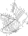
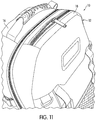
- FIG. 1 shows a tool carrier 10 in accordance with an embodiment of the present invention.
- the tool carrier 10 includes an outer carrier 12 and an inner tool carrier 14.
- the outer carrier 12 comprises a flexible material and includes a main container portion 16 and a cover portion 18.
- the main container portion 16 and the cover portion 18 form a storage space 20.
- the cover portion 18 is movable between open and closed positions, and a zipper 22 enables the cover portion 18 to be releasably secured in the closed position.
- the outer carrier 12 includes a pair of shoulder straps 24 to facilitate carrying of the outer carrier 12.
- the inner tool carrier 14 is constructed and arranged to form a divider (e.g., see FIG. 3 ) within the storage space 20 of the outer carrier 12 and to be removed from the outer carrier 12.
- a divider e.g., see FIG. 3
- the inner tool carrier 14 includes a base portion 26 and a plurality of compartments 28 formed on the base portion 26, and a carrying handle 30 formed on an upper portion 32 of the inner tool carrier 14 to enable the inner tool carrier 14 to be transported separately from the outer carrier 12.
- the base portion 26 includes sufficient rigidity to be self supporting in an upstanding configuration when the inner tool carrier 14 is in the outer carrier 12 to enable the inner tool carrier 14 to support tools within the compartments 28 without collapsing.
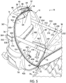
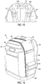
- the main container portion 16 includes a rear wall or portion 34, a pair of side walls 36 and 38 extending from the ends of the rear wall 34, a top wall 40 and a base portion 42 (as shown in FIG. 5 ).
- the rear wall 34, the side walls 36 and 38, the top wall 40, and the base portion 42 are generally rectangular in shape.
- the main container portion 16 may not include a top wall 40.
- the side walls 36 and 38 may extend to be are interconnected with each other along the length of the adjacent edges (e.g., by a sewn seam or otherwise) to define a top or an upper portion 46 of the main container portion 16.
- the rear wall 34, the side walls 36 and 38, the top wall 40, and the base portion 42 are interconnected with each other along the length of the adjacent edges (e.g., by a sewn seam or otherwise) to define an interior of the main container portion 16.
- the base portion 42 of the main container portion 16 may include a rigid panel portion 251.
- the rigid panel portion 251 is constructed and arranged to support the base portion 26 of the inner tool carrier 14.
- the base portion 42 of the main container portion 16 is made from a molded plastic material.
- the base portion 42 in one embodiment, may include a protruding wall 253 surrounding the rigid panel portion 251.
- the protruding wall 253 is constructed and arranged, in one embodiment, to protrude upwardly from the periphery rigid panel portion 251.
- the protruding wall 253 can be integrally molded from plastic together with the panel portion 251, or can be formed separately and then connected.
- the panel portion 251 and protruding wall 253 form somewhat of a cup or bowl shaped configuration that can receive the material of the outer carrier 12.
- the cloth material of the outer carrier 12 includes a bottom portion that overlies the base portion 42.
- the outer carrier 12 has no bottom cloth panel, and instead the lower side portions of the carrier 12 terminate at the portions at which they are sewn or otherwise connected to peripheral protruding wall 253, and in such embodiment the base portion 42 serves as the bottom wall of the outer carrier 12 so that the contents in the outer carrier are directly exposed to the upper surface of the base portion 42.
- a portion of the protruding wall 253 may form an inner panel that is retained between a pair of flexible panels for each of the rear wall 34, and the side walls 36 and 38 of the main container portion 16, thus, connecting the base portion 42 of the main container portion 16 with the rear wall 34, and the side walls 36 and 38 of the main container portion 16.
- a portion of the protruding wall 253 may form an inner panel that is retained between a pair of flexible panels for the cover portion 18, thus, connecting the base portion 42 of the main container portion 16 with the cover portion 18.
- the outer carrier 12 is primarily formed from a flexible material.
- the flexible material of the outer carrier 12 is a cloth material.
- any one, all, or any combination of the rear wall 34, the side walls 36 and 38, and/or the top wall 40 may include a support structure.
- the support structure may include a rigid, semi-rigid, or a flexible (but hard or less flexible in comparison with fabric) inner panel sewn or otherwise retained between a pair of fabric or cloth panels.
- the inner panel may be made from plastic or cardboard, for example, to provide reinforcement to the walls of the main container portion 16 of the outer carrier 12.
- the pair of fabric panels is sewn together along the respective boundaries to retain the inner panel therewithin.
- the one or more support structures along with the relatively rigid base portion 42, enable the outer carrier 12 to be self-supported in an upstanding position (without falling over) when placed on a horizontal surface (as shown in FIG. 16 ).
- a cushion material such as foam is placed in between each fabric panel and the inner panel to provide cushioning characteristics on each side of the walls 34, 36, 38, and 40.
- the base portion 42 of the main container portion 16 may include a plurality of skid resistant members 255 (four are shown in the illustrated embodiment in FIGS. 17 and 18 ) located on exterior surfaces of the base portion 42 of the main compartment portion 16 to facilitate stability and balance of the tool carrier 10 when placed in standing configuration on a horizontal support surface such as the floor.
- the plurality of skid resistant members are attached to the exterior surfaces of the base portion 42 of the main compartment portion 16 using adhesive bonding or other attachment mechanism.
- the skid resistant members may be formed of a material with a high coefficient of friction.
- a handle 44 is connected to the upper portion 46 (e.g., top wall 40) of the main container portion 16 to facilitate carrying of the tool carrier 10.
- the handle 44 comprises a grip securing member 48 and a pair of connector members 50 and 52, extending on either side of the grip securing member 48.
- the pair of connector members 50 and 52 secures the handle 44 to the main container portion 16 of the tool carrier 10 using fasteners.
- the handle 44 facilitates a user a secure grip by hand grip 54.
- the hand grip 54 is attached directly onto the handle 44 and securely conforms to the grip supporting portion 48.
- the grip 54 is in a thick, soft foam rubber.
- the grip 54 is formed from a relatively rigid elastomeric, rubber based, or plastic material.
- the grip 54, or its underlying core may have sufficient rigidity to retain generally its shape (subject to slight flexing) when being carried, in spite of the weight of the items carried in the tool carrier 10.
- the hand grip 54 is secured to the grip supporting portion 48 using adhesive bonding, or any other attachment mechanism as would be appreciated by one skilled in the art.
- the hand grip 54 may include a plurality of protrusions constructed and arranged along the length of the grip 54 that provide an improved gripping action to the user by defining a slip-resistant surface. It should be appreciated, however, that this embodiment is but one example of different types of handles and grip shapes, configurations and/or constructions that can be provided.
- a handle 144 is constructed and arranged to be a part of the shoulder straps 24.
- the handle 144 constructed and arranged to facilitate carrying of the tool carrier 10 is attached to an upper portion 146 of the shoulder straps 24.
- the tool carrier 10 of the present invention may include an extendable or telescopic handle (not shown) operatively connected to the main container portion 16 to facilitate tilted rolling transport of the tool carrier 10, and a pair of roller members (not shown) connected with the main container portion 16 to enable transport of the tool carrier 10 so that the tool carrier 10 may be tilted and pulled or pushed along a horizontal surface (e.g., ground surface) by the user holding the extendable or telescopic handle.
- an extendable or telescopic handle (not shown) operatively connected to the main container portion 16 to facilitate tilted rolling transport of the tool carrier 10
- a pair of roller members (not shown) connected with the main container portion 16 to enable transport of the tool carrier 10 so that the tool carrier 10 may be tilted and pulled or pushed along a horizontal surface (e.g., ground surface) by the user holding the extendable or telescopic handle.
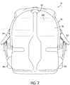
- a plurality of outer compartments or pockets 56 are located on the side walls 36 and 38 of the main container portion 16 to support tools or articles on the exterior surface of the side walls 36 and 38 of the main container portion 16.
- one pocket 56 is located on each side wall 36 or 38 of the main container portion 16.
- the outer pockets 56 are constructed and arranged to be expandable and are configured to support tools or articles on the exterior surface of the side walls 36 and 38 of the main container portion 16.
- the outer pocket 56 is generally constructed of a mesh material or a solid fabric panel and may include an elastic strip sewn or otherwise attached along an upper edge of the outer pocket 56. The elasticity of the elastic strip and the flexibility of the mesh material allow the outer pocket 56 to be resiliently expanded from its relaxed configuration to accommodate and to support tools or articles of various sizes and shapes.
- the outer side pocket 156 is generally constructed of a solid fabric panel and may include a closure flap 58.
- the closure flap 58 is constructed and arranged to overlie at least a portion of the outer side pocket 156.
- the closure flap 58 is integrally formed on the exterior surface of the side walls 36 and 38 of the main container portion 16.
- the closure flap 58 is movable between a closed position and a open position.
- snap connections, Velcro TM connections, or other connections may be used to releasably secure the closure flap 58 in the closed position.
- a plurality of outer pockets may be located on each side wall 36 or 38 of the main container portion 16.
- the plurality of outer side pockets located on each side wall 36 or 38 of the main container portion 16 may include a tiered configuration where outer side pockets are constructed and arranged to be placed in an overlapping relation with each other.
- a plurality of outer compartments or pockets 60 is disposed on an exterior surface of the cover portion 18 for storing tools or articles.
- the outer pockets 60 are constructed and arranged to be expandable and are configured to support tools or articles on the exterior surface of the cover portion 18.
- the compartment 60 is generally constructed of a mesh material and may include an elastic strip sewn or otherwise attached along an upper edge of the outer pocket 60. The elasticity of the elastic strip and the flexibility of the mesh material allow the outer pocket 60 to be resiliently expanded from its relaxed configuration to accommodate and to support tools or articles of various sizes and shapes.
- a plurality of outer compartments or pockets 62 disposed on an exterior surface of the shoulder strap 24 for storing tools or articles.
- the outer pocket 62 is located on the right shoulder strap 24 of the main container portion 16.
- one outer pocket 62 may be located on each shoulder strap 24 of the main container portion 16.
- the outer pockets 62 are constructed and arranged to be expandable and are configured to support tools or articles on the exterior surface of the shoulder strap 24.
- the outer pocket 62 is generally constructed of a mesh material and may include an elastic strip sewn or otherwise attached along an upper edge of the outer pocket 62. The elasticity of the elastic strip and the flexibility of the mesh material allow the outer pocket 62 to be resiliently expanded from its relaxed configuration to accommodate and to support tools or articles of various sizes and shapes.
- the inner pocket or compartment 102 may include a lower inner compartment 104 that is attached to the rear wall 34 of the main container portion 16.
- the lower inner compartment 104 is generally disposed at a predetermined distance (i.e., five centimeters higher than the base portion 42) from the base portion 42 of the main container portion 16.
- the lower inner compartment 104 may include a base wall, a pair of opposing side walls, and a front wall.
- the base wall, the pair of opposing side walls, and the front wall of the lower inner compartment 104 may include a rigid, a semi-rigid, or a flexible (but hard in comparison with fabric) inner panel retained between a pair of fabric panels.
- the inner panel is made from plastic or cardboard to provide reinforcement to the lower inner compartment 104.
- the pair of fabric panels is sewn together along the respective boundaries to retain the inner panel therewithin.
- a cushion material, such as foam is placed in between each fabric panel and the inner panel to provide cushioning characteristics on each side of the lower inner compartment 104.
- the lower inner compartment 104 is constructed and arranged to store power tools therein.
- the inner pocket or compartment 102 may include an upper inner compartment 106.
- the upper inner compartment 106 may be formed from a pair of fabric panels which may include a storage space therewithin.
- the upper ends of the fabric panels are connected to the top wall 40 or the upper portion 46 of the main container portion 16.
- the storage space within the upper inner compartment 106 may be accessed from the exterior of the main container portion 16 (i.e., from the top wall 40 or the upper portion 46 of the main container portion 16).
- the upper inner compartment 106 may be formed by attaching a fabric panel to the rear wall 34 of the main container portion 16, thus, defining a storage space between the rear wall 34 of the main container portion 16 and the fabric panel.
- the fabric panel may be removably attached to the rear wall 34 of the main container portion 16 using zippers, snap connections, velcro TM connections, or other connections.
- a loop or ring having an opening is stitched at a distal end of the fabric panel to receive an end portion of a fastener portion (i.e., attached to the rear wall 34 of the main container portion 16), thus, removably attaching the fabric panel to the rear wall 34 of the main container portion 16.
- any one, all, or any combination of the inner pocket 102 and outer pockets 56, 60, 62 and 156 may be independent from the main container portion 16 such that the inner pocket 102 and outer pockets 56, 60, 62 and 156 may be detached from the main container portion 16 to be carried separately.
- at least a portion of the inner pocket 102 and outer pockets 56, 60, 62 and 156 may be removably attached to the main container portion 16 using zippers, buttons, clasps, snap connections, Velcro TM connections, or other connections.
- the cover portion 18 is attached to the main container portion 16 using previously described zipper 22, which are arranged along the length of at least a portion of edges of the side walls 36 and 38 of the main container portion 16 and on opposite edges of the cover portion 18.
- a lower edge 70 (as shown in FIG. 5 ) of the cover portion 18 may be permanently attached to the tool carrier 10.
- the zipper 20 is generally disposed at an angle with respect to the edges of the side walls 36 and 38 of the main container portion 16. This configuration of the zipper provides easy access to the tools and/or articles stored in the inner tool carrier 14, which is positioned in the storage space 20 of the outer carrier 12.
- the outer carrier 12 may include an adjustable fastening structure 200 attached to an interior surface 201 (shown in FIGS. 2 and 3 ) of the main container portion 16 and an interior surface 203 (shown in FIGS. 2 and 3 ) of the cover portion 18.
- the fastening structure 200 is constructed and arranged to adjust the permitted separation between the main container portion 16 and the cover portion 18.
- the fastening structure 200 comprises an adjustable strap 200, and the strap 200 is divided into two strap portions 202 and 204.
- the first fastener portion 202 and the second fastener portion 204 are releasably engaged with each other to connect the main container portion 16 and the cover portion 18 of the outer carrier 12.
- the first fastener portion 202 is attached to the cover portion 18 and the second fastener portion 204 is attached to the main container portion 16.
- the first fastener portion 202 is attached to the main container portion 16 and the second fastener portion 204 is attached to the cover portion 18.
- the first fastener portion 202 and the second fastener portion 204 may be attached to the interior surface 201 of the main container portion 16 or the interior surface 203 of the cover portion 18 by stitching or by other attachment as would be appreciated by one skilled in the art.
- the first fastener portion 202 includes a ring or loop 216 stitched at a distal end 218 thereof.
- the loop 216 defines an opening 208 constructed and arranged to receive an end portion 210 of the second fastener portion 204 therethrough.
- the end 218 of the first fastener portion 202 is passed through at least a portion of the ring or loop 216 and is looped back onto itself and connected (e.g., stitched) to attach the ring or loop 216 with the first fastener portion 202.
- At least a first portion 210 of the second fastener portion 204 is constructed and arranged to pass through the opening 208 of the first fastener portion 202 to selectively couple with second portion 212 of the second fastener portion 204 and to connect main container portion 16 and the cover portion 18 of the outer carrier 12.
- the second fastener portion 204 can be inserted into the opening 208 such that the hooks (e.g., male Velcro TM ) located on the rear section of the first portion 210 can engage with the loops (e.g., female Velcro TM ) on the second portion 212 of the second fastener portion 204, to secure the adjustable fastening structure 200 at the desired length.
- the first portion 210 of the second fastener portion 204 includes a strip or a pad with a plurality of hooks
- the second portion 212 of the second fastener portion 204 includes a strip or a pad with a plurality of loops.
- the second fastener portion 204 is attached to the main container portion 16 of the outer carrier 12 or the cover portion 18 of the outer carrier 12 by stitching or by otherwise attaching at least a base or opposite end portion 220 (as shown in FIG. 2 ) of the second fastener portion 204 to the main container portion 16 of the outer carrier 12 or the cover portion 18 of the outer carrier 12.
- the outer carrier 12 may include a second adjustable fastening structure 300 attached to exterior surfaces of the main container portion 16.
- the second fastening structure 300 is constructed and arranged to adjust width of the main container portion 16.
- the second fastening structure 300 is attached to a first edge portion 301 of the side wall 36 or 38 of the main container portion 16 and a second edge portion 303 of the side wall 36 or 38 of the main container portion 16.
- the second fastening structure 300 comprises an adjustable strap 300, and the strap 300 is divided into two strap portions 302 and 304.
- the first fastener portion 302 and the second fastener portion 304 may be attached to the first edge portion 301 of the side wall 36 or 38 of the main container portion 16 or the second edge portion 303 of the side wall 36 or 38 of the main container portion 16 by stitching or by other attachment as would be appreciated by one skilled in the art.
- the first fastener portion 302 includes a ring or loop 316 stitched at a distal end 318 thereof.
- the loop 316 defines an opening 308 constructed and arranged to receive an end portion 310 of the second fastener portion 304 therethrough.
- the end 318 of the first fastener portion 302 is passed through at least a portion of the ring or loop 316 and is looped back onto itself and connected (e.g., stitched) to attach the ring or loop 316 with the first fastener portion 302.
- At least a first portion 310 of the second fastener portion 304 is constructed and arranged to pass through the opening 308 of the first fastener portion 302 to selectively couple with second portion 312 of the second fastener portion 304 and to adjust width of the main container portion 16.
- the second fastener portion 304 can be inserted into the opening 308 such that the hooks (e.g., male Velcro TM ) located on the rear section of the first portion 310 can engage with the loops (e.g., female Velcro TM ) on the second portion 312 of the second fastener portion 304, to secure the second adjustable fastening structure 300 at the desired length.
- the first portion 310 of the second fastener portion 304 includes a strip or a pad with a plurality of hooks
- the second portion 312 of the second fastener portion 304 includes a strip or a pad with a plurality of loops.
- the second fastener portion 304 is attached to the first edge portion 301 of the side wall 36 or 38 of the main container portion 16 or the second edge portion 303 of the side wall 36 or 38 of the main container portion 16 by stitching or by otherwise attaching at least a base or opposite end portion 320 (as shown in FIG. 1 ) of the second fastener portion 304 to the first edge portion 301 of the side wall 36 or 38 of the main container portion 16 or the second edge portion 303 of the side wall 36 or 38 of the main container portion 16.
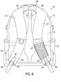
- a portion 100 of the rear wall 34 of the main container portion 16 may include a cushion material to provide increased comfort to a user.
- the cushion material such as foam is placed in between a mesh material and the exterior surface of the rear wall 34 of the main container portion 16 to provide cushioning characteristics on each side of the base portion 26.
- the pair of shoulder straps 24 is constructed and arranged to facilitate carrying of the outer carrier 12.
- upper ends 90 of the shoulder straps 24 are sewn or otherwise attached along edges of the top wall 40 or the upper portion 46 of the main container portion 16.
- the upper ends 90 of shoulder strap 24 are sewn or otherwise attached along edges of the side walls 36 and 38 of the main container portion 16.
- each shoulder strap 24 may include a first strap portion 92 near a lower end 94 of the shoulder strap 24.
- the first strap portion 92 is configured to connect directly to a buckle 96.
- the buckle 96 may be used on each of the shoulder straps 24 to provide the shoulder straps 24 with an adjustable length.
- a second strap portion 98 is threaded through the buckle 96 to provide adjustable length to the shoulder straps 24.
- the adjustable strap portion 98 is constructed and arranged to connect (i.e., sewn or otherwise attach) the lower ends 94 of the shoulder straps 24 to the edges of the side walls 36 and 38 of the main container portion 16 using the buckle 96.
- the shoulder straps 24 may be made from any material and construction, for example, fabric webbing, conventionally used for shoulder straps.
- the shoulder straps 24 may include a cushioned material or a padded material (i.e., attached to or integral with the shoulder straps 24) for comfortably securing the tool carrier 10 to the user's shoulders.
- the outer carrier 12 may include a fastening structure 400 that is attached to an interior surface of the base portion 42 of the main container portion 16.
- the fastening structure 400 is constructed and arranged to attach the inner tool carrier 14 to the outer carrier 12.
- the fastening structure 400 is attached to a first edge portion 401 that joins one of the side walls 36 or 38 with the base portion 42 of the main container portion 16 and a second edge portion 403 that joins the other of the side walls 36 or 38 with the base portion 42 of the main container portion 16.
- the fastening structure 400 includes a strap 400, and the strap 400 is divided into two strap portions 402 and 404.
- the first fastener portion 402 and the second fastener portion 404 may be attached to the first edge portion 401 of the main container portion 16 or the second edge portion 403 of the main container portion 16 by stitching or by other attachment as would be appreciated by one skilled in the art.
- the first fastener portion 402 includes a fastener 416 stitched at a distal end 418 thereof.
- the end 418 of the first fastener portion 402 is passed through at least a portion of the fastener 416 and is looped back onto itself and connected (e.g., stitched) to attach the fastener 416 with the first fastener portion 402.
- an end portion 410 of the second fastener portion 404 is passed through at least a portion of a fastener 415 and is looped back onto itself and connected (e.g., stitched) to attach the fastener 415 with the second fastener portion 404.
- the fastener 416 is constructed and arranged to mate with or receive the fastener 415 attached to the end portion 410 of the second fastener portion 404 to selectively couple with the second fastener portion 404 and to attach the inner tool carrier 14 to the outer carrier 12.
- the fasteners 415 and 416 may include snap connections, Velcro TM connections, or other connections that may be used to releasably secure the inner tool carrier 14 with the outer carrier 12.
- the inner tool carrier 14 is constructed and arranged to be removed from the outer carrier 12, while FIGS. 2-4 show the inner tool carrier 14 constructed and arranged to form a divider within the storage space 20 of the outer carrier 12.
- the base portion 26 includes sufficient rigidity to be self supporting in an upstanding configuration when the inner tool carrier 14 is within the outer carrier 12 to enable the inner tool carrier 14 to support tools within the compartments 28 without collapsing.
- the base portion 26 of the inner tool carrier 14 may include a rigid, a semi-rigid, or a flexible (but hard in comparison with fabric) inner panel retained between a pair of fabric panels.
- the inner panel is made from plastic or cardboard to provide reinforcement to the base portion 26.
- the pair of fabric panels is sewn together along the respective boundaries to retain the inner panel therewithin.
- a cushion material, such as foam is placed in between each fabric panel and the inner panel to provide cushioning characteristics on each side of the base portion 26.
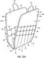
- FIGS. 12A-12C there is a plurality of compartments 28 formed on a rear surface portion 86 and a front surface portion 88 of the base portion 26 of the inner tool carrier 14.
- the inner tool carrier 14 may include two base portions 26A and 26B that are joined with each other using a connector member 84.
- the connector member 84 may be constructed and arranged to be parallel to the base portion 42 of the main container portion 16.
- Each of the base portion 26A and 26B may include the carrying handle 30 formed on the upper portion 32 thereof to enable the inner tool carrier 14 to be transported separately from the outer carrier 12.
- the inner tool carrier 14 is attached to the outer carrier 12 first by positioning the inner tool carrier 14 in the storage space 20 of the outer carrier 12.
- a connector portion 84 of the inner tool carrier 14 is disposed generally parallel to the base portion 42 of the main container portion 16 of the outer carrier 12.
- the fastener 416 of the first fastener portion 402 i.e., connected to the first edge portion 401 of the main container portion 16
- the fastener 415 of the second fastener portion 404 i.e., connected to the second edge portion 403 of the main container portion 16
- the fastener 416 of the first fastener portion 402 i.e., connected to the first edge portion 401 of the main container portion 16
- the fastener 415 of the second fastener portion 404 i.e., connected to the second edge portion 403 of the main container portion 16
- the inner tool carrier 14 may include a single base portion 26.
- the base portion 26 may include the carrying handle 30 formed on the upper portion 32 thereof to enable the inner tool carrier 14 to be transported separately from the outer carrier 12, and the plurality of compartments 28 formed on the rear surface portion 86 and the front surface portion 88 of the base portion 26 of the inner tool carrier 14.
- the base portion 26 may include a fastener portion formed on the lower portion thereof to facilitate the attachment of the inner tool carrier 14 with the outer carrier 12.
- the inner tool carrier 14 is attached to the outer carrier 12 first by positioning the inner tool carrier 14 in the storage space 20 of the outer carrier 12.
- the fastener portion formed on the lower portion of the base portion 26 is connected with a fastener portion on the base portion 42 of the main container portion 16, thus, attaching the inner tool carrier 14 with the outer carrier 12 and minimizing the movement of the inner tool carrier 14 within the storage space 20 of the outer carrier 12.
- the fastener portions on the inner tool carrier 14 and the outer carrier 12 may include snap connections, Velcro TM connections, or other connections that may be used to releasably secure the inner tool carrier 14 with the outer carrier 12.
- FIGS. 12A-12C show the plurality of compartments 28 formed on the base portion 26 of the inner tool carrier 14.
- Each compartment 28 formed on the base portion 26 of the inner tool carrier 14 includes a plurality of individual containing regions 72 arranged adjacent to each other along the length of the compartment 28.
- the individual containing regions 72 are formed by stitching or by otherwise attaching the compartment 28 at regular intervals along the length of the compartment 28.
- the individual containing regions 72 are adapted to organize one or more tools or articles in each individual containing region 72.
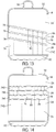
- the compartments 28 are arranged in a staged relationship, overlapping each other.
- the inner tool carrier 14 may include a first compartment 74A, a second compartment 74B, and a third compartment 74C formed on the front surface portion 88 and a first compartment 74D, a second compartment 74E, a third compartment 74F, and a fourth compartment 74G formed on the rear surface portion 86.
- the compartments 74A-74C can be arranged in a staged relationship overlapping each other providing compartments for storing longer or larger tools or articles in deeper, more rearward compartments, such as the first compartment 74A, and for storing shorter or smaller tools or articles in other compartments, such as the second, and the third compartment 74B, and 74C respectively.
- the compartments 74D-74G can be arranged in a staged relationship overlapping each other providing compartments for storing longer or larger tools or articles in deeper, more rearward compartments, such as the first compartment 74D, and for storing shorter or smaller tools or articles in other compartments, such as the second, and the third compartment 74E, 74F and 74G respectively.
- each compartment 28 comprises a fabric panel 76 with an elastic strip 78 sewn or otherwise attached along upper edges 80 of the compartments 28.
- the elasticity of the elastic strip 78 allows each compartment 28 to be resiliently expanded from its relaxed configuration to accommodate and to support tools or articles of various sizes and shapes. It should be appreciated that it is within the scope of the present invention to provide only a single (at least one) compartment 28 on the front or rear surface portions, or with individual containing regions 72 different than those illustrated herein and adapted to receive different types of items.
- each compartment 28 includes the upper edge 80 defining an upwardly facing opening disposed at an angle with respect to a lower portion 82 of the inner tool carrier 14.
- the angle each upper edge 80 of compartment 74A-74C makes with the lower portion 82 of the inner tool carrier 14 generally remains constant.
- each compartment 28 is arranged such that the compartment 28 is sloping downwardly from left to right, or from right to left.
- the upper edge 80 of the compartments 28 formed on the base portion 26 is parallel to the lower portion 82 of the inner tool carrier 14.
Landscapes
- Engineering & Computer Science (AREA)
- Mechanical Engineering (AREA)
- Purses, Travelling Bags, Baskets, Or Suitcases (AREA)
Claims (15)
- Porte-outils (10), comprenant :un support extérieur (12) comprenant une matière souple et ayant une partie formant conteneur principal et une partie formant couvercle (18), la partie formant conteneur principal et la partie formant couvercle (18) définissant un espace de rangement, la partie formant couvercle (18) étant mobile entre des positions ouverte et fermée, une fermeture à glissière qui permet à la partie formant couvercle (18) d'être fixée de façon amovible dans la position fermée, le support extérieur (12) comprenant un couple de bretelles pour faciliter le transport du support extérieur (12) ; etun porte-outils intérieur (14) construit et agencé pour former un séparateur à l'intérieur de l'espace de rangement du support extérieur (12) et être enlevé du support extérieur (12), le porte-outils intérieur (14) comprenant une partie de base (26) et une pluralité de compartiments exposés (28) formés sur la partie de base, et une poignée de transport (30) formée sur une partie supérieure du porte-outils intérieur (14) pour permettre au porte-outils intérieur (14) d'être transporté séparément du support extérieur (12), la partie de base (26) ayant une rigidité suffisante pour être autoporteuse dans une configuration verticale lorsque le porte-outils intérieur (14) est dans le support extérieur (12) pour permettre au porte-outils intérieur (14) de supporter des outils à l'intérieur des compartiments (28) sans effondrement,caractérisé en ce que le support extérieur (12) comprend une partie de base de support extérieur (42) comprenant une structure rigide ou semi-rigide, la partie de base de support extérieur (42) est construite et agencée pour permettre au support extérieur (12) d'être autoporté dans une configuration droite lorsque placé sur une surface horizontale, etdans lequel lorsque le support extérieur (12) est dans la configuration droite et que la partie formant couvercle (18) est dans la position ouverte, le porte-outils intérieur (14) est exposé, et est dans la configuration verticale dans la partie de base de support extérieur (42) et est construit et agencé pour faciliter l'accès aux compartiments (28) des deux côtés de ce dernier.
- Porte-outils selon la revendication 1, dans lequel la pluralité de compartiments (28) est formée sur une partie formant surface arrière (86) et une partie formant surface avant (88) de la partie de base (26).
- Porte-outils selon la revendication 1 ou 2, dans lequel les compartiments (28) formés sur la partie de base (26) comprennent une pluralité de régions individuelles contenant (72) agencées adjacentes les unes aux autres pour ranger un ou plusieurs outils ou articles.
- Porte-outils selon l'une quelconque des revendications 1 à 3, dans lequel les compartiments (28) formés sur la partie de base (26) sont agencés dans une relation étagée se chevauchant.
- Porte-outils selon la revendication 4, dans lequel un bord supérieur (80) des compartiments (28) formés sur la partie de base (26) est parallèle à une partie inférieure (82) du porte-outils intérieur (14).
- Porte-outils selon la revendication 5, dans lequel un bord supérieur (80) des compartiments (28) formés sur la partie de base (26) est disposé à un certain angle par rapport à une partie inférieure (82) du porte-outils intérieur (14).
- Porte-outils selon l'une quelconque des revendications 1 à 6, comprenant en outre une structure de fixation réglable (200) fixée à un intérieur de la partie formant conteneur principal (16) et à un intérieur de la partie formant couvercle (18), dans lequel la structure de fixation est construite et agencée pour ajuster la séparation entre la partie formant conteneur principal (16) et la partie formant couvercle (18).
- Porte-outils selon la revendication 7, dans lequel la structure de fixation (200) comprend une première partie formant dispositif de fixation (202) et une seconde partie formant dispositif de fixation (204), qui sont en prise de façon amovible l'une avec l'autre pour relier la partie formant conteneur principal (16) et la partie formant couvercle (18) du support extérieur.
- Porte-outils selon la revendication 8, dans lequel la première partie formant dispositif de fixation (202) est fixée à l'intérieur de la partie formant conteneur principal (16) et la seconde partie formant dispositif de fixation (204) est fixée à l'intérieur de la partie formant couvercle (18).
- Porte-outils selon la revendication 8 ou 9, dans lequel la première partie formant dispositif de fixation (202) comprend une ouverture (208) construite et agencée pour recevoir une première partie (210) de la seconde partie formant dispositif de fixation (204) à travers cette dernière.
- Porte-outils selon l'une quelconque des revendications 1 à 10, comprenant en outre un compartiment de rangement (56, 156) disposé sur un extérieur de la partie formant couvercle (18) pour ranger des outils et des articles.
- Porte-outils selon l'une quelconque des revendications 1 à 11, comprenant en outre une seconde structure de fixation réglable (300) disposée sur un extérieur de la partie formant conteneur principal (16), dans lequel la structure de fixation est construite et agencée pour ajuster la largeur de la partie formant conteneur principal.
- Porte-outils selon l'une quelconque des revendications 1 à 12, comprenant en outre une poignée (144) reliée aux bretelles (24), dans lequel la poignée est construite et agencée pour faciliter le transport du porte-outils.
- Porte-outils selon l'une quelconque des revendications 1 à 13, dans lequel une partie inférieure (82) du porte-outils intérieur (14) est construite et agencée pour attacher le porte-outils intérieur au support extérieur (12).
- Porte-outils selon l'une quelconque des revendications 1 à 14, comprenant en outre une structure de fixation (400) disposée dans un intérieur de la partie formant conteneur principal (16), dans lequel la structure de fixation (400) est construite et agencée pour attacher le porte-outils intérieur (14) avec le support extérieur (12).
Priority Applications (1)
| Application Number | Priority Date | Filing Date | Title |
|---|---|---|---|
| EP09156229.8A EP2233254B1 (fr) | 2009-03-25 | 2009-03-25 | Support d'outils |
Applications Claiming Priority (1)
| Application Number | Priority Date | Filing Date | Title |
|---|---|---|---|
| EP09156229.8A EP2233254B1 (fr) | 2009-03-25 | 2009-03-25 | Support d'outils |
Publications (2)
| Publication Number | Publication Date |
|---|---|
| EP2233254A1 EP2233254A1 (fr) | 2010-09-29 |
| EP2233254B1 true EP2233254B1 (fr) | 2017-04-19 |
Family
ID=40552070
Family Applications (1)
| Application Number | Title | Priority Date | Filing Date |
|---|---|---|---|
| EP09156229.8A Active EP2233254B1 (fr) | 2009-03-25 | 2009-03-25 | Support d'outils |
Country Status (1)
| Country | Link |
|---|---|
| EP (1) | EP2233254B1 (fr) |
Families Citing this family (12)
| Publication number | Priority date | Publication date | Assignee | Title |
|---|---|---|---|---|
| JP2011230255A (ja) * | 2010-04-28 | 2011-11-17 | Makita Corp | 工具収容バッグ及び工具収容バッグセット |
| DE102012205145B4 (de) | 2012-03-29 | 2015-02-12 | BSH Bosch und Siemens Hausgeräte GmbH | Tragbares Behältnis, insbesondere Rucksack |
| AU2013327809B2 (en) | 2013-02-26 | 2016-12-15 | Veto Pro Pac, Llc | Supported composite tool pack |
| JP2015128570A (ja) * | 2013-12-06 | 2015-07-16 | 節子 高橋 | 仕切り型小物収納具 |
| JP6545939B2 (ja) * | 2014-08-29 | 2019-07-17 | 富士通株式会社 | 表示デバイスの収容体 |
| GB2569048B (en) * | 2014-09-03 | 2020-03-04 | Mark Garratt Daniel | A storage device for medical equipment |
| GB2531240A (en) | 2014-09-03 | 2016-04-20 | Daniel Mark Garratt | A storage device for medical equipment |
| US9642443B2 (en) * | 2015-03-26 | 2017-05-09 | Nike, Inc. | Backpack with closure mechanisms |
| US10442075B2 (en) * | 2016-05-26 | 2019-10-15 | Ty-Flot, Inc. | Tool pack system with removable tool panels |
| US10165845B2 (en) * | 2016-05-26 | 2019-01-01 | Ty-Flot, Inc. | Tool pack system with removable tool panels |
| CN115038356A (zh) * | 2020-01-30 | 2022-09-09 | 宣伟公司 | 为粉刷工具设计和组织的背包 |
| EP3942964A1 (fr) * | 2020-07-23 | 2022-01-26 | A7 Fitness Inc. | Sac d'exercice |
Family Cites Families (9)
| Publication number | Priority date | Publication date | Assignee | Title |
|---|---|---|---|---|
| US4285556A (en) * | 1980-02-25 | 1981-08-25 | Emil Loeffel | Tool chest |
| US4793508A (en) * | 1985-09-09 | 1988-12-27 | Thompson Priscilla B | Structure for detachably receiving at least one retaining board in variable configuration |
| US4854432A (en) * | 1988-07-06 | 1989-08-08 | American Tourister, Inc. | Suitcase having removable divider with clothing pockets |
| US5209384A (en) | 1990-08-31 | 1993-05-11 | Anderson Scott M | Portable tool kit |
| US6105764A (en) * | 1999-02-11 | 2000-08-22 | Tumi, Inc. | Computer carrying case |
| US6474524B1 (en) * | 1999-11-16 | 2002-11-05 | Jeffrey J. Ivarson | Backpack apparatus |
| US6915902B2 (en) * | 2002-10-02 | 2005-07-12 | Veto Pro Pac, Llc | Tool bag |
| US6948600B2 (en) * | 2003-03-28 | 2005-09-27 | Yao-Tang Chuang | Carrier bag fetching structure |
| US7712645B2 (en) * | 2006-04-19 | 2010-05-11 | Calkin Carston R | Medical chest bag for military, emergency rescue and other personnel |
-
2009
- 2009-03-25 EP EP09156229.8A patent/EP2233254B1/fr active Active
Non-Patent Citations (1)
| Title |
|---|
| None * |
Also Published As
| Publication number | Publication date |
|---|---|
| EP2233254A1 (fr) | 2010-09-29 |
Similar Documents
| Publication | Publication Date | Title |
|---|---|---|
| EP2233254B1 (fr) | Support d'outils | |
| EP2116338B1 (fr) | Sac à outils | |
| US10350746B2 (en) | Tool storage devices | |
| US6550592B1 (en) | Collapsible storage and carrying case | |
| US7210426B2 (en) | Compressible pet carrier | |
| US5779112A (en) | Back pack with seat | |
| US8146787B2 (en) | Carrying bag | |
| US20080197756A1 (en) | Tool Bag with Attached Compartment | |
| US20070164064A1 (en) | Convertible storage bag | |
| EP1880630A2 (fr) | Mécanisme de positionnement réglable et sac ou receptacle, tel qu'un sac à dos ou autre, équipé d'un tel mécanisme | |
| US20120228171A1 (en) | Tool case for engaging a ladder | |
| US20130233661A1 (en) | Integrated multi-component travel and backpack | |
| US9427055B2 (en) | Multipurpose carrier | |
| US20110176752A1 (en) | Garden bag | |
| US20060180421A1 (en) | Pet carrier with wheels | |
| US20160242519A1 (en) | Convertible container assembly | |
| US20110233084A1 (en) | Storage System for Archery Equipment and Accessories | |
| US20100237110A1 (en) | Modular backpack system | |
| US7073694B2 (en) | Hybrid construction for a luggage case | |
| US20130327803A1 (en) | Load carrying pack system | |
| US20140124558A1 (en) | Configurable bag having faceplates | |
| US20170112266A1 (en) | Utility Belt | |
| US20130020368A1 (en) | Ergonomic backpack | |
| KR102230291B1 (ko) | 백팩 | |
| KR101978188B1 (ko) | 모듈식 서랍 가방 |
Legal Events
| Date | Code | Title | Description |
|---|---|---|---|
| PUAI | Public reference made under article 153(3) epc to a published international application that has entered the european phase |
Free format text: ORIGINAL CODE: 0009012 |
|
| AK | Designated contracting states |
Kind code of ref document: A1 Designated state(s): AT BE BG CH CY CZ DE DK EE ES FI FR GB GR HR HU IE IS IT LI LT LU LV MC MK MT NL NO PL PT RO SE SI SK TR |
|
| AX | Request for extension of the european patent |
Extension state: AL BA RS |
|
| 17P | Request for examination filed |
Effective date: 20100923 |
|
| AKX | Designation fees paid |
Designated state(s): AT BE BG CH CY CZ DE DK EE ES FI FR GB GR HR HU IE IS IT LI LT LU LV MC MK MT NL NO PL PT RO SE SI SK TR |
|
| 17Q | First examination report despatched |
Effective date: 20120706 |
|
| GRAP | Despatch of communication of intention to grant a patent |
Free format text: ORIGINAL CODE: EPIDOSNIGR1 |
|
| INTG | Intention to grant announced |
Effective date: 20161109 |
|
| GRAS | Grant fee paid |
Free format text: ORIGINAL CODE: EPIDOSNIGR3 |
|
| GRAA | (expected) grant |
Free format text: ORIGINAL CODE: 0009210 |
|
| AK | Designated contracting states |
Kind code of ref document: B1 Designated state(s): AT BE BG CH CY CZ DE DK EE ES FI FR GB GR HR HU IE IS IT LI LT LU LV MC MK MT NL NO PL PT RO SE SI SK TR |
|
| REG | Reference to a national code |
Ref country code: GB Ref legal event code: FG4D |
|
| REG | Reference to a national code |
Ref country code: CH Ref legal event code: EP |
|
| REG | Reference to a national code |
Ref country code: AT Ref legal event code: REF Ref document number: 885506 Country of ref document: AT Kind code of ref document: T Effective date: 20170515 |
|
| REG | Reference to a national code |
Ref country code: IE Ref legal event code: FG4D |
|
| REG | Reference to a national code |
Ref country code: DE Ref legal event code: R096 Ref document number: 602009045500 Country of ref document: DE |
|
| REG | Reference to a national code |
Ref country code: NL Ref legal event code: MP Effective date: 20170419 |
|
| REG | Reference to a national code |
Ref country code: LT Ref legal event code: MG4D |
|
| REG | Reference to a national code |
Ref country code: AT Ref legal event code: MK05 Ref document number: 885506 Country of ref document: AT Kind code of ref document: T Effective date: 20170419 |
|
| PG25 | Lapsed in a contracting state [announced via postgrant information from national office to epo] |
Ref country code: NL Free format text: LAPSE BECAUSE OF FAILURE TO SUBMIT A TRANSLATION OF THE DESCRIPTION OR TO PAY THE FEE WITHIN THE PRESCRIBED TIME-LIMIT Effective date: 20170419 |
|
| PG25 | Lapsed in a contracting state [announced via postgrant information from national office to epo] |
Ref country code: GR Free format text: LAPSE BECAUSE OF FAILURE TO SUBMIT A TRANSLATION OF THE DESCRIPTION OR TO PAY THE FEE WITHIN THE PRESCRIBED TIME-LIMIT Effective date: 20170720 Ref country code: NO Free format text: LAPSE BECAUSE OF FAILURE TO SUBMIT A TRANSLATION OF THE DESCRIPTION OR TO PAY THE FEE WITHIN THE PRESCRIBED TIME-LIMIT Effective date: 20170719 Ref country code: FI Free format text: LAPSE BECAUSE OF FAILURE TO SUBMIT A TRANSLATION OF THE DESCRIPTION OR TO PAY THE FEE WITHIN THE PRESCRIBED TIME-LIMIT Effective date: 20170419 Ref country code: LT Free format text: LAPSE BECAUSE OF FAILURE TO SUBMIT A TRANSLATION OF THE DESCRIPTION OR TO PAY THE FEE WITHIN THE PRESCRIBED TIME-LIMIT Effective date: 20170419 Ref country code: ES Free format text: LAPSE BECAUSE OF FAILURE TO SUBMIT A TRANSLATION OF THE DESCRIPTION OR TO PAY THE FEE WITHIN THE PRESCRIBED TIME-LIMIT Effective date: 20170419 Ref country code: AT Free format text: LAPSE BECAUSE OF FAILURE TO SUBMIT A TRANSLATION OF THE DESCRIPTION OR TO PAY THE FEE WITHIN THE PRESCRIBED TIME-LIMIT Effective date: 20170419 Ref country code: HR Free format text: LAPSE BECAUSE OF FAILURE TO SUBMIT A TRANSLATION OF THE DESCRIPTION OR TO PAY THE FEE WITHIN THE PRESCRIBED TIME-LIMIT Effective date: 20170419 |
|
| PG25 | Lapsed in a contracting state [announced via postgrant information from national office to epo] |
Ref country code: PL Free format text: LAPSE BECAUSE OF FAILURE TO SUBMIT A TRANSLATION OF THE DESCRIPTION OR TO PAY THE FEE WITHIN THE PRESCRIBED TIME-LIMIT Effective date: 20170419 Ref country code: BG Free format text: LAPSE BECAUSE OF FAILURE TO SUBMIT A TRANSLATION OF THE DESCRIPTION OR TO PAY THE FEE WITHIN THE PRESCRIBED TIME-LIMIT Effective date: 20170719 Ref country code: SE Free format text: LAPSE BECAUSE OF FAILURE TO SUBMIT A TRANSLATION OF THE DESCRIPTION OR TO PAY THE FEE WITHIN THE PRESCRIBED TIME-LIMIT Effective date: 20170419 Ref country code: IS Free format text: LAPSE BECAUSE OF FAILURE TO SUBMIT A TRANSLATION OF THE DESCRIPTION OR TO PAY THE FEE WITHIN THE PRESCRIBED TIME-LIMIT Effective date: 20170819 Ref country code: LV Free format text: LAPSE BECAUSE OF FAILURE TO SUBMIT A TRANSLATION OF THE DESCRIPTION OR TO PAY THE FEE WITHIN THE PRESCRIBED TIME-LIMIT Effective date: 20170419 |
|
| REG | Reference to a national code |
Ref country code: DE Ref legal event code: R097 Ref document number: 602009045500 Country of ref document: DE |
|
| PG25 | Lapsed in a contracting state [announced via postgrant information from national office to epo] |
Ref country code: CZ Free format text: LAPSE BECAUSE OF FAILURE TO SUBMIT A TRANSLATION OF THE DESCRIPTION OR TO PAY THE FEE WITHIN THE PRESCRIBED TIME-LIMIT Effective date: 20170419 Ref country code: EE Free format text: LAPSE BECAUSE OF FAILURE TO SUBMIT A TRANSLATION OF THE DESCRIPTION OR TO PAY THE FEE WITHIN THE PRESCRIBED TIME-LIMIT Effective date: 20170419 Ref country code: SK Free format text: LAPSE BECAUSE OF FAILURE TO SUBMIT A TRANSLATION OF THE DESCRIPTION OR TO PAY THE FEE WITHIN THE PRESCRIBED TIME-LIMIT Effective date: 20170419 Ref country code: DK Free format text: LAPSE BECAUSE OF FAILURE TO SUBMIT A TRANSLATION OF THE DESCRIPTION OR TO PAY THE FEE WITHIN THE PRESCRIBED TIME-LIMIT Effective date: 20170419 Ref country code: RO Free format text: LAPSE BECAUSE OF FAILURE TO SUBMIT A TRANSLATION OF THE DESCRIPTION OR TO PAY THE FEE WITHIN THE PRESCRIBED TIME-LIMIT Effective date: 20170419 |
|
| PLBE | No opposition filed within time limit |
Free format text: ORIGINAL CODE: 0009261 |
|
| STAA | Information on the status of an ep patent application or granted ep patent |
Free format text: STATUS: NO OPPOSITION FILED WITHIN TIME LIMIT |
|
| PG25 | Lapsed in a contracting state [announced via postgrant information from national office to epo] |
Ref country code: IT Free format text: LAPSE BECAUSE OF FAILURE TO SUBMIT A TRANSLATION OF THE DESCRIPTION OR TO PAY THE FEE WITHIN THE PRESCRIBED TIME-LIMIT Effective date: 20170419 |
|
| 26N | No opposition filed |
Effective date: 20180122 |
|
| PG25 | Lapsed in a contracting state [announced via postgrant information from national office to epo] |
Ref country code: SI Free format text: LAPSE BECAUSE OF FAILURE TO SUBMIT A TRANSLATION OF THE DESCRIPTION OR TO PAY THE FEE WITHIN THE PRESCRIBED TIME-LIMIT Effective date: 20170419 |
|
| REG | Reference to a national code |
Ref country code: CH Ref legal event code: PL |
|
| PG25 | Lapsed in a contracting state [announced via postgrant information from national office to epo] |
Ref country code: MC Free format text: LAPSE BECAUSE OF FAILURE TO SUBMIT A TRANSLATION OF THE DESCRIPTION OR TO PAY THE FEE WITHIN THE PRESCRIBED TIME-LIMIT Effective date: 20170419 |
|
| REG | Reference to a national code |
Ref country code: BE Ref legal event code: MM Effective date: 20180331 |
|
| REG | Reference to a national code |
Ref country code: IE Ref legal event code: MM4A |
|
| PG25 | Lapsed in a contracting state [announced via postgrant information from national office to epo] |
Ref country code: LU Free format text: LAPSE BECAUSE OF NON-PAYMENT OF DUE FEES Effective date: 20180325 |
|
| PG25 | Lapsed in a contracting state [announced via postgrant information from national office to epo] |
Ref country code: IE Free format text: LAPSE BECAUSE OF NON-PAYMENT OF DUE FEES Effective date: 20180325 |
|
| PG25 | Lapsed in a contracting state [announced via postgrant information from national office to epo] |
Ref country code: BE Free format text: LAPSE BECAUSE OF NON-PAYMENT OF DUE FEES Effective date: 20180331 Ref country code: CH Free format text: LAPSE BECAUSE OF NON-PAYMENT OF DUE FEES Effective date: 20180331 Ref country code: LI Free format text: LAPSE BECAUSE OF NON-PAYMENT OF DUE FEES Effective date: 20180331 |
|
| PG25 | Lapsed in a contracting state [announced via postgrant information from national office to epo] |
Ref country code: FR Free format text: LAPSE BECAUSE OF NON-PAYMENT OF DUE FEES Effective date: 20180331 |
|
| PG25 | Lapsed in a contracting state [announced via postgrant information from national office to epo] |
Ref country code: MT Free format text: LAPSE BECAUSE OF NON-PAYMENT OF DUE FEES Effective date: 20180325 |
|
| PG25 | Lapsed in a contracting state [announced via postgrant information from national office to epo] |
Ref country code: TR Free format text: LAPSE BECAUSE OF FAILURE TO SUBMIT A TRANSLATION OF THE DESCRIPTION OR TO PAY THE FEE WITHIN THE PRESCRIBED TIME-LIMIT Effective date: 20170419 |
|
| PG25 | Lapsed in a contracting state [announced via postgrant information from national office to epo] |
Ref country code: HU Free format text: LAPSE BECAUSE OF FAILURE TO SUBMIT A TRANSLATION OF THE DESCRIPTION OR TO PAY THE FEE WITHIN THE PRESCRIBED TIME-LIMIT; INVALID AB INITIO Effective date: 20090325 Ref country code: PT Free format text: LAPSE BECAUSE OF FAILURE TO SUBMIT A TRANSLATION OF THE DESCRIPTION OR TO PAY THE FEE WITHIN THE PRESCRIBED TIME-LIMIT Effective date: 20170419 |
|
| PG25 | Lapsed in a contracting state [announced via postgrant information from national office to epo] |
Ref country code: MK Free format text: LAPSE BECAUSE OF NON-PAYMENT OF DUE FEES Effective date: 20170419 Ref country code: CY Free format text: LAPSE BECAUSE OF FAILURE TO SUBMIT A TRANSLATION OF THE DESCRIPTION OR TO PAY THE FEE WITHIN THE PRESCRIBED TIME-LIMIT Effective date: 20170419 |
|
| PGFP | Annual fee paid to national office [announced via postgrant information from national office to epo] |
Ref country code: DE Payment date: 20220203 Year of fee payment: 14 |
|
| REG | Reference to a national code |
Ref country code: DE Ref legal event code: R119 Ref document number: 602009045500 Country of ref document: DE |
|
| PG25 | Lapsed in a contracting state [announced via postgrant information from national office to epo] |
Ref country code: DE Free format text: LAPSE BECAUSE OF NON-PAYMENT OF DUE FEES Effective date: 20231003 |
|
| PGFP | Annual fee paid to national office [announced via postgrant information from national office to epo] |
Ref country code: GB Payment date: 20240322 Year of fee payment: 16 |