EP2233191A1 - Filter cleaning apparatus and method of cleaning filter - Google Patents
Filter cleaning apparatus and method of cleaning filter Download PDFInfo
- Publication number
- EP2233191A1 EP2233191A1 EP08702886A EP08702886A EP2233191A1 EP 2233191 A1 EP2233191 A1 EP 2233191A1 EP 08702886 A EP08702886 A EP 08702886A EP 08702886 A EP08702886 A EP 08702886A EP 2233191 A1 EP2233191 A1 EP 2233191A1
- Authority
- EP
- European Patent Office
- Prior art keywords
- filter
- cleaning
- processing container
- bubble flow
- liquid
- Prior art date
- Legal status (The legal status is an assumption and is not a legal conclusion. Google has not performed a legal analysis and makes no representation as to the accuracy of the status listed.)
- Withdrawn
Links
Images

Classifications
-
- B—PERFORMING OPERATIONS; TRANSPORTING
- B08—CLEANING
- B08B—CLEANING IN GENERAL; PREVENTION OF FOULING IN GENERAL
- B08B3/00—Cleaning by methods involving the use or presence of liquid or steam
- B08B3/04—Cleaning involving contact with liquid
- B08B3/10—Cleaning involving contact with liquid with additional treatment of the liquid or of the object being cleaned, e.g. by heat, by electricity or by vibration
- B08B3/102—Cleaning involving contact with liquid with additional treatment of the liquid or of the object being cleaned, e.g. by heat, by electricity or by vibration with means for agitating the liquid
-
- B—PERFORMING OPERATIONS; TRANSPORTING
- B01—PHYSICAL OR CHEMICAL PROCESSES OR APPARATUS IN GENERAL
- B01D—SEPARATION
- B01D41/00—Regeneration of the filtering material or filter elements outside the filter for liquid or gaseous fluids
- B01D41/04—Regeneration of the filtering material or filter elements outside the filter for liquid or gaseous fluids of rigid self-supporting filtering material
-
- B—PERFORMING OPERATIONS; TRANSPORTING
- B08—CLEANING
- B08B—CLEANING IN GENERAL; PREVENTION OF FOULING IN GENERAL
- B08B3/00—Cleaning by methods involving the use or presence of liquid or steam
- B08B3/04—Cleaning involving contact with liquid
-
- B—PERFORMING OPERATIONS; TRANSPORTING
- B08—CLEANING
- B08B—CLEANING IN GENERAL; PREVENTION OF FOULING IN GENERAL
- B08B3/00—Cleaning by methods involving the use or presence of liquid or steam
- B08B3/04—Cleaning involving contact with liquid
- B08B3/10—Cleaning involving contact with liquid with additional treatment of the liquid or of the object being cleaned, e.g. by heat, by electricity or by vibration
Definitions
- the present invention relates to a technique of cleaning a filter mounted on a powder and granular material processing apparatus and particularly to a cleaning process for a cartridge filter having a pleated structure.
- a powder and granular material processing apparatus such as a fluidized bed granulation coating apparatus that performs a process of granulating by using a gas flow to fluidize a finely divided substance and other processes.
- a gas is supplied to fluidize powder and granular material;
- a filter is provided to separate powder and granular material from the exhaust thereof. The filter filtered out the powder and granular material that is fluidized by gas flow; only the gas is separated and released to the outside of the powder and granular material processing apparatus.
- a pleated filter made from filter cloth is often used in order to increase a filtering area.
- the clogging of the filter medium hampers the flow of the gas and the fluidization of the powder and granular material, leading to a decrease in processing efficiency. Therefore, in order to prevent the filter medium from getting clogged, fine powder adhering to the filter medium is dusted off when necessary.
- the dusting off of fine powder is carried out by supplying pulse air in a direction opposite to that of a fluidized gas flow.
- a wet cleaning method such as the one disclosed in Patent Document 1
- the pleated filter is so set as to be capable of rotating; a cleaning liquid is obliquely jetted to the periphery of the pleated filter.
- the filter that receives the cleaning liquid rotates inside a cleaning apparatus.
- the cleaning liquid is intensively and efficiently jetted to the entire surface of the filter. Accordingly, the fine powder that is stuck in the recesses of the pleat is removed to the outside of the filter by centrifugal force; an efficient cleaning process is carried out.
- a method has been proposed to dispose a filter in a processing container filled with the cleaning liquid, jet a bubble flow or a cleaning liquid (or water) plus a bubble flow instead of the cleaning liquid, and rotate the filter in the liquid for cleaning.
- the obj active of the present invention is to provide a filter cleaning apparatus and a cleaning method that enable a cartridge filter used in a fluidized bed granulator or the like to be cleaned efficiently.
- a filter cleaning apparatus is characterized by including: a processing container that is so formed as to be capable of retaining a cleaning liquid and housing a filter used in a powder and granular material processing apparatus in such a way that the filter can rotate in the state that the cleaning liquid is poured and retained; and a nozzle device that is attached to the processing container and jets a bubble flow or a liquid containing bubbles to the filter being immersed in the cleaning liquid to rotate and clean the filter in the cleaning liquid, wherein the filter is so disposed as to be capable of rotating around a rotational axis line that is substantially horizontal in the processing container, and the nozzle device is disposed below the filter.
- the filter is so disposed as to be capable of rotating around the rotational axis line that is substantially horizontal, and the nozzle device is disposed below the filter. Therefore, an uplift pressure of bubbles rising out of the liquid into the atmosphere is added to the bubble flow or the liquid containing bubbles jetted from the nozzle device. As a result of the synergic effect of the jet pressure of the bubble flow and the uplift pressure, the filter rotates in an efficient way.
- the processing container may include: a filter supporting member that supports a rotational axis attached to the center of the filter in such a way that the rotational axis can rotate; and a nozzle device that jets a bubble flow or a liquid containing bubbles from below the filter to the filter.
- the filter may be a cartridge filter having a pleated structure, such as a cylindrical cartridge filter formed by pleating a filter cloth.
- a filter cleaning method of cleaning a filter used in a powder and granular material processing apparatus housing the filter in a processing container in which a cleaning liquid is reserved; is characterized by including the steps of: disposing the filter in the processing container with the center of the filter aligned with a rotational axis line that is substantially horizontal in such a way that the filter can rotate; and jetting a bubble flow or a liquid containing bubbles from a nozzle device disposed below the filter in the processing container to the filter in the tangential direction to rotate and clean the filter by the bubble flow or the liquid containing bubbles.
- the filter may be a cartridge filter having a pleated structure.
- the filter is disposed in the processing container with the center of the filter aligned with the rotational axis line that is substantially horizontal in such a way that the filter can rotate; and a bubble flow or a liquid containing bubbles is jetted from the nozzle device disposed below the filter to the filter in the tangential direction to rotate and clean the filter by the bubble flow or the liquid containing bubbles. Therefore, an uplift pressure of bubbles rising out of the liquid into the atmosphere is added to the bubble flow jetted from the nozzle device. As a result of the synergic effect of the jet pressure of the bubble flow and the uplift pressure, the filter rotates in an efficient way, leading to an improvement in cleaning efficiency.
- the filter cleaning apparatus of the present invention where the filter is put in the processing container in which the cleaning liquid is reserved and a cleaning process is carried out by rotating the filter by means of the bubble flow or the liquid containing bubbles jetted from the nozzle device attached to the processing container, the filter is so disposed as to be capable of rotating around the rotational axis line that is substantially horizontal, and the nozzle device is disposed below the filter. Therefore, an uplift pressure of bubbles rising out of the liquid into the atmosphere is added to the bubble flow jetted from the nozzle device. As a result of the synergic effect of the jet pressure of the bubble flow and the uplift pressure, the filter rotates in an efficient way, thereby enabling the energy of the bubbles to be used efficiently and making an efficient cleaning process possible.
- the filter cleaning method of the present invention by which the filter is put in the processing container in which the cleaning liquid is reserved and a cleaning process is carried out by rotating the filter by means of the bubble flow or the liquid containing bubbles jetted from the nozzle device attached to the processing container, the filter is so disposed as to be capable of rotating around the rotational axis line that is substantially horizontal in the processing container, and the bubble flow or the liquid containing bubbles is jetted from the nozzle device disposed below the filter to the filter in the tangential direction to rotate and clean the filter by the bubble flow or the liquid containing bubbles. Therefore, an uplift pressure of bubbles rising out of the liquid into the atmosphere is added to the bubble flow jetted from the nozzle device. As a result of the synergic effect of the jet pressure of the bubble flow and the uplift pressure, the filter rotates in an efficient way, thereby enabling the energy of the bubbles to be used efficiently and making an efficient cleaning process possible.
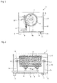
- FIG. 1 is an explanatory diagram illustrating the configuration of a filter cleaning apparatus according to an embodiment of the present invention, and a cross-sectional view of the device as viewed in the lateral direction.
- FIG. 2 is a cross-sectional view of the filter cleaning apparatus of FIG. 1 as viewed in the front direction.
- the filter cleaning apparatus 1 of FIG. 1 is a cleaning apparatus for a cartridge filter used in a powder and granular material processing apparatus such as a fluidized bed granulation coating device and is formed separately from the powder and granular material processing apparatus.
- the filter cleaning apparatus 1 is a cleaning apparatus designed exclusively for the cartridge filter. After being removed from the powder and granular material processing apparatus, the cartridge filter is cleaned inside the filter cleaning apparatus 1.
- the filter cleaning apparatus 1 is equipped with a processing container 2 formed in the shape of a box.
- the processing container 2 is filled with a cleaning liquid 10.
- a cartridge filter 3 (simply referred to as filter 3, hereinafter) is immersed in the cleaning liquid 10 and then rotated by a bubble flow BF or the like to carry out a cleaning process.
- the processing container 2 made of acrylic resin is transparent, enabling what is happening inside, or how the filter is being cleaned, to be viewed from the outside of the device.
- Attached to the bottom of the processing container 2 is a base plate 4 made of metal such as stainless steel. Attached to the bottom face of the base plate 4 are supporting legs 5. Thanks to the supporting legs 5, the processing container 2 is put on the surface of a floor.
- the filter 3 is laterally laid in the processing container 2 (with the rotational axis being set in the horizontal direction).
- filter supporting plates (filter supporting members) 6a and 6b stand on the base plate 4 of the processing container 2.
- the filter 3 is attached to the upper ends of the filter supporting plates 6a and 6b so as to be capable of rotating.
- a rotational axis 7 is attached to the filter 3.
- the rotational axis 7 is supported by the filter supporting plates 6a and 6b so as to be capable of rotating. That is, the filter 3 is set in the processing container 2 so as to be capable of rotating around a rotational axis line O that is substantially horizontal.
- air nozzles (nozzle device) 9 are installed to supply a bubble flow.
- An air supply pipe 9 is connected to the air nozzles 8. Compressed air is supplied to the air nozzles 8 from an external compressor (not shown) through the air supply pipe 9.
- an external compressor not shown
- FIG. 2 there are two air nozzles 8 that are arranged along a long side of the device. Attached to the undersurface of the base plate 4 is a drain 11, allowing the cleaning liquid 10 inside the processing container 2 to be released down from the drain 11 to the outside of the container.
- the filter cleaning apparatus 1 when compressed air is supplied to the air nozzles 8 through the air supply pipe 9, the bubble flow BF is jetted, upward from the air nozzles 8 to the filter 3.
- the bubble flow BF is jetted from the air nozzles 8 in the tangential direction to the filter 3.
- the filter 3 rotates around the rotational axis 7.
- an uplift pressure (buoyant force) of bubbles rising out of the liquid into the atmosphere is added to the jet pressure of the bubble flow BF jetted from the air nozzles 8.
- the filter 3 rotates in an efficient way.
- the filter 3 is laterally laid in the processing container 2; the bubble flow BF is supplied from below the filter 3 to the filter 3.
- the rotating force is applied at right angles to the filter 3, thereby enabling the energy of the bubbles to be used efficiently and allowing the filter 3 to rotate in an excellent manner. Therefore, it is possible to carry out an efficient cleaning process.
- the filter cleaning apparatus 1 improves in cleaning efficiency, a sufficient cleaning effect is obtained only with the bubble flow BF without using a water flow in combination with the bubble flow. Therefore, the cleaning process can be carried out in a desired manner without the supply of both the water and bubble flows. Accordingly, a circulation path for a cleaning liquid that needs to be installed when a water flow is used is unnecessary. In this case, the drain 11 for releasing the liquid is satisfactory for the processing container 2, making the configuration of the device simple. Needless to say, the filter cleaning apparatus of the present invention is able to use both the water and bubble flows in the cleaning process.
- an ultrasonic cleaning device may be also used in order to improve the cleaning effect.
- bubbling jet nozzles may be used.
- the number of the air nozzles 8 is not limited to two; the number may vary depending on the size of the filter 3 when needed.
- the liquid surface S of the cleaning liquid 10 is lower in position than the upper end of the filter 3; the filter 3 is not completely submerged in the cleaning liquid 10.
- the liquid surface S may change in position when necessary.
- the material of the processing container 2 is not limited to acrylic resin; the processing container 2 may be made of metal such as stainless steel, FRP, or the like.
Abstract
Description
- The present invention relates to a technique of cleaning a filter mounted on a powder and granular material processing apparatus and particularly to a cleaning process for a cartridge filter having a pleated structure.
- In the field of medicine, cosmetics and food, various products are made through such processes as granulating, coating, mixing and drying of a finely divided substance like powder or powder and granular material. For such processes, a powder and granular material processing apparatus is used such as a fluidized bed granulation coating apparatus that performs a process of granulating by using a gas flow to fluidize a finely divided substance and other processes. In such a powder and granular material processing apparatus, a gas is supplied to fluidize powder and granular material; a filter is provided to separate powder and granular material from the exhaust thereof. The filter filtered out the powder and granular material that is fluidized by gas flow; only the gas is separated and released to the outside of the powder and granular material processing apparatus.
- As a filter used for the powder and granular material processing apparatus, a pleated filter made from filter cloth is often used in order to increase a filtering area. However, in such a filter, the clogging of the filter medium hampers the flow of the gas and the fluidization of the powder and granular material, leading to a decrease in processing efficiency. Therefore, in order to prevent the filter medium from getting clogged, fine powder adhering to the filter medium is dusted off when necessary. The dusting off of fine powder is carried out by supplying pulse air in a direction opposite to that of a fluidized gas flow.
- However, even such a dust-off process cannot dust off the powder adhering to the filter completely. The resistance against the flow of air increases as the powder gradually accumulates. Accordingly, it is necessary to perform a cleaning process of the filter separately after a predetermined period of processing in case of performing granulation and other processes. In particular, when a pleated filter is used, the fine powder that is stuck in the recesses of the pleat tends to agglomerate. Moreover, it is difficult even for backwashing air to reach the recesses of the pleat. Therefore, it is difficult to sufficiently remove fine powder in the recesses of the pleat.
- For a pleated filter or the like, a wet cleaning method, such as the one disclosed in
Patent Document 1, has been proposed in which the filter is rotated for cleaning. According to the cleaning method, the pleated filter is so set as to be capable of rotating; a cleaning liquid is obliquely jetted to the periphery of the pleated filter. The filter that receives the cleaning liquid rotates inside a cleaning apparatus. The cleaning liquid is intensively and efficiently jetted to the entire surface of the filter. Accordingly, the fine powder that is stuck in the recesses of the pleat is removed to the outside of the filter by centrifugal force; an efficient cleaning process is carried out. In addition, a method has been proposed to dispose a filter in a processing container filled with the cleaning liquid, jet a bubble flow or a cleaning liquid (or water) plus a bubble flow instead of the cleaning liquid, and rotate the filter in the liquid for cleaning. - Patent Document 1:
- Jpn. Pat. Appln. Laid-Open Publication No.
6-262015 - Patent Document 2:
- Jpn. Pat. Appln. Laid-Open Publication No.
10-235168 - Patent Document 3:
- Jpn. Pat. Appln. Laid-Open Publication No.
2004-97936 - However, for a device, like the one disclosed in
Patent Document 1, in which a filter is longitudinally put in a processing container (with the rotational axis being set in the vertical direction) and the filter is rotated for cleaning with a cleaning liquid, bubble flow or the like being jetted in the lateral direction (horizontal direction) toward the filter, an efficient cleaning process may be impossible. For example, as shown inFIG. 3 , according to a method of laterally jetting a bubble flow or the like 54 with afilter 53 longitudinally put in aprocessing container 52 filled with a cleaningliquid 51, the bubble flow or the like 54 jetted from anozzle 55 rises into the atmosphere after jet. Accordingly, the bubble flow or the like 54 does not hit thefilter 53 at right angles; the use of the bubble flow or the like alone may not be enough to make the cleaning process efficient. - The obj active of the present invention is to provide a filter cleaning apparatus and a cleaning method that enable a cartridge filter used in a fluidized bed granulator or the like to be cleaned efficiently.
- According to the present invention, a filter cleaning apparatus is characterized by including: a processing container that is so formed as to be capable of retaining a cleaning liquid and housing a filter used in a powder and granular material processing apparatus in such a way that the filter can rotate in the state that the cleaning liquid is poured and retained; and a nozzle device that is attached to the processing container and jets a bubble flow or a liquid containing bubbles to the filter being immersed in the cleaning liquid to rotate and clean the filter in the cleaning liquid, wherein the filter is so disposed as to be capable of rotating around a rotational axis line that is substantially horizontal in the processing container, and the nozzle device is disposed below the filter.
- According to the present invention, the filter is so disposed as to be capable of rotating around the rotational axis line that is substantially horizontal, and the nozzle device is disposed below the filter. Therefore, an uplift pressure of bubbles rising out of the liquid into the atmosphere is added to the bubble flow or the liquid containing bubbles jetted from the nozzle device. As a result of the synergic effect of the jet pressure of the bubble flow and the uplift pressure, the filter rotates in an efficient way.
- In the filter cleaning apparatus, the processing container may include: a filter supporting member that supports a rotational axis attached to the center of the filter in such a way that the rotational axis can rotate; and a nozzle device that jets a bubble flow or a liquid containing bubbles from below the filter to the filter. The filter may be a cartridge filter having a pleated structure, such as a cylindrical cartridge filter formed by pleating a filter cloth.
- According to the present invention, a filter cleaning method of cleaning a filter used in a powder and granular material processing apparatus, housing the filter in a processing container in which a cleaning liquid is reserved; is characterized by including the steps of: disposing the filter in the processing container with the center of the filter aligned with a rotational axis line that is substantially horizontal in such a way that the filter can rotate; and jetting a bubble flow or a liquid containing bubbles from a nozzle device disposed below the filter in the processing container to the filter in the tangential direction to rotate and clean the filter by the bubble flow or the liquid containing bubbles. In this case, the filter may be a cartridge filter having a pleated structure.
- According to the present invention, the filter is disposed in the processing container with the center of the filter aligned with the rotational axis line that is substantially horizontal in such a way that the filter can rotate; and a bubble flow or a liquid containing bubbles is jetted from the nozzle device disposed below the filter to the filter in the tangential direction to rotate and clean the filter by the bubble flow or the liquid containing bubbles. Therefore, an uplift pressure of bubbles rising out of the liquid into the atmosphere is added to the bubble flow jetted from the nozzle device. As a result of the synergic effect of the jet pressure of the bubble flow and the uplift pressure, the filter rotates in an efficient way, leading to an improvement in cleaning efficiency.
- According to the filter cleaning apparatus of the present invention where the filter is put in the processing container in which the cleaning liquid is reserved and a cleaning process is carried out by rotating the filter by means of the bubble flow or the liquid containing bubbles jetted from the nozzle device attached to the processing container, the filter is so disposed as to be capable of rotating around the rotational axis line that is substantially horizontal, and the nozzle device is disposed below the filter. Therefore, an uplift pressure of bubbles rising out of the liquid into the atmosphere is added to the bubble flow jetted from the nozzle device. As a result of the synergic effect of the jet pressure of the bubble flow and the uplift pressure, the filter rotates in an efficient way, thereby enabling the energy of the bubbles to be used efficiently and making an efficient cleaning process possible.
- According to the filter cleaning method of the present invention by which the filter is put in the processing container in which the cleaning liquid is reserved and a cleaning process is carried out by rotating the filter by means of the bubble flow or the liquid containing bubbles jetted from the nozzle device attached to the processing container, the filter is so disposed as to be capable of rotating around the rotational axis line that is substantially horizontal in the processing container, and the bubble flow or the liquid containing bubbles is jetted from the nozzle device disposed below the filter to the filter in the tangential direction to rotate and clean the filter by the bubble flow or the liquid containing bubbles. Therefore, an uplift pressure of bubbles rising out of the liquid into the atmosphere is added to the bubble flow jetted from the nozzle device. As a result of the synergic effect of the jet pressure of the bubble flow and the uplift pressure, the filter rotates in an efficient way, thereby enabling the energy of the bubbles to be used efficiently and making an efficient cleaning process possible.
-
-
FIG. 1 is an explanatory diagram illustrating the configuration of a filter cleaning apparatus according to an embodiment of the present invention, and a cross-sectional view of the device as viewed in the lateral direction. -
FIG. 2 is a cross-sectional view of the filter cleaning apparatus ofFIG. 1 as viewed in the front direction. -
FIG. 3 is an explanatory diagram illustrating a cleaning process by a conventional filter cleaning apparatus. -
- 1:
- Filter cleaning apparatus
- 2:
- Processing container
- 3:
- Cartridge filter
- 4:
- Base plate
- 5:
- Supporting legs
- 6a, 6b:
- Filter supporting plates (filter supporting members)
- 7:
- Rotational axis
- 8:
- Air nozzles (nozzle device)
- 9:
- Air supply pipe
- 10:
- Cleaning liquid
- 11:
- Drain
- 51:
- Cleaning liquid
- 52:
- Processing container
- 53:
- Filter
- 54:
- Bubble flow or the like
- 55:
- Nozzle
- BF:
- Bubble flow
- O:
- Rotational axis line
- S:
- Liquid surface
-
FIG. 1 is an explanatory diagram illustrating the configuration of a filter cleaning apparatus according to an embodiment of the present invention, and a cross-sectional view of the device as viewed in the lateral direction.FIG. 2 is a cross-sectional view of the filter cleaning apparatus ofFIG. 1 as viewed in the front direction. Thefilter cleaning apparatus 1 ofFIG. 1 is a cleaning apparatus for a cartridge filter used in a powder and granular material processing apparatus such as a fluidized bed granulation coating device and is formed separately from the powder and granular material processing apparatus. Thefilter cleaning apparatus 1 is a cleaning apparatus designed exclusively for the cartridge filter. After being removed from the powder and granular material processing apparatus, the cartridge filter is cleaned inside thefilter cleaning apparatus 1. - As shown in
FIGS. 1 and 2 , thefilter cleaning apparatus 1 is equipped with aprocessing container 2 formed in the shape of a box. Theprocessing container 2 is filled with a cleaningliquid 10. In thefilter cleaning apparatus 1, a cartridge filter 3 (simply referred to asfilter 3, hereinafter) is immersed in the cleaningliquid 10 and then rotated by a bubble flow BF or the like to carry out a cleaning process. Theprocessing container 2 made of acrylic resin is transparent, enabling what is happening inside, or how the filter is being cleaned, to be viewed from the outside of the device. Attached to the bottom of theprocessing container 2 is abase plate 4 made of metal such as stainless steel. Attached to the bottom face of thebase plate 4 are supportinglegs 5. Thanks to the supportinglegs 5, theprocessing container 2 is put on the surface of a floor. - In the
filter cleaning apparatus 1, thefilter 3 is laterally laid in the processing container 2 (with the rotational axis being set in the horizontal direction). On thebase plate 4 of theprocessing container 2, filter supporting plates (filter supporting members) 6a and 6b stand. Thefilter 3 is attached to the upper ends of thefilter supporting plates rotational axis 7 is attached to thefilter 3. Therotational axis 7 is supported by thefilter supporting plates filter 3 is set in theprocessing container 2 so as to be capable of rotating around a rotational axis line O that is substantially horizontal. - In a bottom portion of the
processing container 2, air nozzles (nozzle device) 9 are installed to supply a bubble flow. Anair supply pipe 9 is connected to theair nozzles 8. Compressed air is supplied to theair nozzles 8 from an external compressor (not shown) through theair supply pipe 9. As shown inFIG. 2 , there are twoair nozzles 8 that are arranged along a long side of the device. Attached to the undersurface of thebase plate 4 is adrain 11, allowing the cleaningliquid 10 inside theprocessing container 2 to be released down from thedrain 11 to the outside of the container. - In the
filter cleaning apparatus 1, when compressed air is supplied to theair nozzles 8 through theair supply pipe 9, the bubble flow BF is jetted, upward from theair nozzles 8 to thefilter 3. The bubble flow BF is jetted from theair nozzles 8 in the tangential direction to thefilter 3. Thanks to the bubble flow BF, thefilter 3 rotates around therotational axis 7. At this time, an uplift pressure (buoyant force) of bubbles rising out of the liquid into the atmosphere is added to the jet pressure of the bubble flow BF jetted from theair nozzles 8. As a result of the synergic effect of the jet pressure and the uplift pressure, thefilter 3 rotates in an efficient way. - As described above, in the
filter cleaning apparatus 1, thefilter 3 is laterally laid in theprocessing container 2; the bubble flow BF is supplied from below thefilter 3 to thefilter 3. By the uplift pressure of the bubbles, the rotating force is applied at right angles to thefilter 3, thereby enabling the energy of the bubbles to be used efficiently and allowing thefilter 3 to rotate in an excellent manner. Therefore, it is possible to carry out an efficient cleaning process. - As the
filter cleaning apparatus 1 improves in cleaning efficiency, a sufficient cleaning effect is obtained only with the bubble flow BF without using a water flow in combination with the bubble flow. Therefore, the cleaning process can be carried out in a desired manner without the supply of both the water and bubble flows. Accordingly, a circulation path for a cleaning liquid that needs to be installed when a water flow is used is unnecessary. In this case, thedrain 11 for releasing the liquid is satisfactory for theprocessing container 2, making the configuration of the device simple. Needless to say, the filter cleaning apparatus of the present invention is able to use both the water and bubble flows in the cleaning process. - Needless to say, the present invention is not limited to the above embodiment and can be modified in various ways without departing from the scope of the invention.
For example, in thefilter cleaning apparatus 1 illustrated inFIG. 1 , an ultrasonic cleaning device may be also used in order to improve the cleaning effect. Instead of theair nozzles 8, bubbling jet nozzles may be used. The number of theair nozzles 8 is not limited to two; the number may vary depending on the size of thefilter 3 when needed. InFIGS 1 and 2 , in theprocessing container 2, the liquid surface S of the cleaningliquid 10 is lower in position than the upper end of thefilter 3; thefilter 3 is not completely submerged in the cleaningliquid 10. However, the liquid surface S may change in position when necessary. The material of theprocessing container 2 is not limited to acrylic resin; theprocessing container 2 may be made of metal such as stainless steel, FRP, or the like.
Claims (5)
- A filter cleaning apparatus characterized by comprising:a processing container that is so formed as to be capable of retaining a cleaning liquid and housing a filter used in a powder and granular material processing apparatus in such a way that the filter can rotate in the state that the cleaning liquid is poured and retained; anda nozzle device that is attached to the processing container and jets a bubble flow or a liquid containing bubbles to the filter being immersed in the cleaning liquid to rotate and clean the filter in the cleaning liquid, whereinthe filter is so disposed as to be capable of rotating around a rotational axis line that is substantially horizontal in the processing container, and the nozzle device is disposed below the filter.
- The filter cleaning apparatus according to claim 1, characterized in that
the processing container includes:a filter supporting member that is disposed in the processing container to support a rotational axis attached to the center of the filter in such a way that the rotational axis can rotate; anda nozzle device that is disposed in a bottom portion of the processing container and jets a bubble flow or a liquid containing bubbles from below the filter to the filter. - The filter cleaning apparatus according to claim 1, characterized in that
the filter is a cartridge filter having a pleated structure. - A filter cleaning method of cleaning a filter used in a powder and granular material processing apparatus, housing the filter in a processing container in which a a cleaning liquid is reserved, characterized by comprising the steps of:disposing the filter in the processing container with the center of the filter aligned with a rotational axis line that is substantially horizontal in such a way that the filter can rotate; andjetting a bubble flow or a liquid containing bubbles from a nozzle device disposed below the filter in the processing container to the filter in the tangential direction to rotate and clean the filter by the bubble flow or the liquid containing bubbles.
- The filter cleaning method according to claim 4, characterized in that
the filter is a cartridge filter having a pleated structure.
Applications Claiming Priority (1)
| Application Number | Priority Date | Filing Date | Title |
|---|---|---|---|
| PCT/JP2008/050005 WO2009087750A1 (en) | 2008-01-04 | 2008-01-04 | Filter cleaning apparatus and method of cleaning filter |
Publications (2)
| Publication Number | Publication Date |
|---|---|
| EP2233191A1 true EP2233191A1 (en) | 2010-09-29 |
| EP2233191A4 EP2233191A4 (en) | 2013-09-04 |
Family
ID=40852875
Family Applications (1)
| Application Number | Title | Priority Date | Filing Date |
|---|---|---|---|
| EP08702886.6A Withdrawn EP2233191A4 (en) | 2008-01-04 | 2008-01-04 | Filter cleaning apparatus and method of cleaning filter |
Country Status (3)
| Country | Link |
|---|---|
| US (1) | US20100258147A1 (en) |
| EP (1) | EP2233191A4 (en) |
| WO (1) | WO2009087750A1 (en) |
Cited By (3)
| Publication number | Priority date | Publication date | Assignee | Title |
|---|---|---|---|---|
| CN105617766A (en) * | 2014-11-07 | 2016-06-01 | 中国石油天然气股份有限公司 | Basket type filtration screen washing machine |
| CN105999861A (en) * | 2016-07-29 | 2016-10-12 | 江门市河正环保设备有限公司 | Filter element cleaning machine |
| CN105999860A (en) * | 2016-07-29 | 2016-10-12 | 江门市河正环保设备有限公司 | Water-cycle filter element cleaning machine |
Families Citing this family (8)
| Publication number | Priority date | Publication date | Assignee | Title |
|---|---|---|---|---|
| EP2179685B1 (en) * | 2008-10-23 | 2013-01-09 | Electrolux Home Products Corporation N.V. | Dishwasher |
| CA2735756A1 (en) * | 2011-03-31 | 2012-09-30 | Craig Hopf | Weed and trash screening apparatus for irrigation systems |
| CN102500566B (en) * | 2011-09-22 | 2014-01-15 | 清华大学 | Maintenance-free slurry washer applied to hazardous environment and working method of maintenance-free slurry washer |
| CN102423763B (en) * | 2011-10-20 | 2013-09-04 | 天脊煤化工集团股份有限公司 | Anti-scarring method and device for discharge chute of granulating machine |
| JP5589021B2 (en) * | 2012-04-19 | 2014-09-10 | 株式会社栗本鐵工所 | Filter cleaning device |
| US9550139B2 (en) | 2014-03-04 | 2017-01-24 | Vincent James Madonia | Apparatus and system for cleaning a filter |
| US9808840B2 (en) * | 2014-10-15 | 2017-11-07 | Saudi Arabian Oil Company | Air filter ultrasonic cleaning systems and the methods of using the same |
| CN116447858B (en) * | 2023-03-16 | 2024-01-30 | 江苏赛隆环境工程有限公司 | Ultra-large environment-friendly high-efficiency energy-saving drying box |
Citations (4)
| Publication number | Priority date | Publication date | Assignee | Title |
|---|---|---|---|---|
| JPS57117305A (en) * | 1981-01-09 | 1982-07-21 | Hitachi Ltd | Regeneration of oil-separating element |
| JPS59195651A (en) * | 1983-04-21 | 1984-11-06 | Nec Corp | Device for washing photomask |
| US20080006290A1 (en) * | 2006-07-10 | 2008-01-10 | Kuniaki Yamanaka | Fluidized bed apparatus and filter washing method for fluidized bed apparatus |
| JP2008279429A (en) * | 2007-04-13 | 2008-11-20 | Freunt Ind Co Ltd | Filter cleaning apparatus and filter cleaning method |
Family Cites Families (5)
| Publication number | Priority date | Publication date | Assignee | Title |
|---|---|---|---|---|
| EP0572356B1 (en) | 1992-05-26 | 1996-12-04 | Niro-Aeromatic Ag | Apparatus and process for cleaning with a liquid of filter cartridges in fluidised powder apparatus or in spray-dryers |
| JP3031402B2 (en) * | 1993-11-29 | 2000-04-10 | 株式会社石垣 | External pressure type membrane filtration device |
| JPH10235168A (en) | 1997-02-24 | 1998-09-08 | Mitsubishi Rayon Co Ltd | Filter cleaning method |
| JP2001232309A (en) * | 2000-02-24 | 2001-08-28 | Kazuo Arai | Washing method for cylindrical air filter and cylindrical air filter washing device |
| JP3751274B2 (en) * | 2002-09-09 | 2006-03-01 | エムイーテクノス株式会社 | Filter cleaning device |
-
2008
- 2008-01-04 EP EP08702886.6A patent/EP2233191A4/en not_active Withdrawn
- 2008-01-04 US US12/808,259 patent/US20100258147A1/en not_active Abandoned
- 2008-01-04 WO PCT/JP2008/050005 patent/WO2009087750A1/en active Application Filing
Patent Citations (4)
| Publication number | Priority date | Publication date | Assignee | Title |
|---|---|---|---|---|
| JPS57117305A (en) * | 1981-01-09 | 1982-07-21 | Hitachi Ltd | Regeneration of oil-separating element |
| JPS59195651A (en) * | 1983-04-21 | 1984-11-06 | Nec Corp | Device for washing photomask |
| US20080006290A1 (en) * | 2006-07-10 | 2008-01-10 | Kuniaki Yamanaka | Fluidized bed apparatus and filter washing method for fluidized bed apparatus |
| JP2008279429A (en) * | 2007-04-13 | 2008-11-20 | Freunt Ind Co Ltd | Filter cleaning apparatus and filter cleaning method |
Non-Patent Citations (1)
| Title |
|---|
| See also references of WO2009087750A1 * |
Cited By (4)
| Publication number | Priority date | Publication date | Assignee | Title |
|---|---|---|---|---|
| CN105617766A (en) * | 2014-11-07 | 2016-06-01 | 中国石油天然气股份有限公司 | Basket type filtration screen washing machine |
| CN105617766B (en) * | 2014-11-07 | 2017-09-01 | 中国石油天然气股份有限公司 | A kind of basket screen pack cleaning machine |
| CN105999861A (en) * | 2016-07-29 | 2016-10-12 | 江门市河正环保设备有限公司 | Filter element cleaning machine |
| CN105999860A (en) * | 2016-07-29 | 2016-10-12 | 江门市河正环保设备有限公司 | Water-cycle filter element cleaning machine |
Also Published As
| Publication number | Publication date |
|---|---|
| WO2009087750A1 (en) | 2009-07-16 |
| US20100258147A1 (en) | 2010-10-14 |
| EP2233191A4 (en) | 2013-09-04 |
Similar Documents
| Publication | Publication Date | Title |
|---|---|---|
| EP2233191A1 (en) | Filter cleaning apparatus and method of cleaning filter | |
| JP5100358B2 (en) | Filter cleaning device and filter cleaning method | |
| JP5161437B2 (en) | Fluidized bed apparatus and filter cleaning method in fluidized bed apparatus | |
| ES2526450T3 (en) | Method and device for cleaning media filters not fixed | |
| JP4994709B2 (en) | Fluidized bed equipment | |
| JP4734077B2 (en) | Filter cleaning apparatus and filter cleaning method for powder processing apparatus | |
| EP3445482B1 (en) | A reactor comprising a nozzle for cleaning fluid and a method | |
| JP5300209B2 (en) | Suspended substance filtration device with filter cleaning nozzle | |
| JP2008093783A (en) | Filter device | |
| JP2013138971A (en) | Filtering device | |
| JP2007301486A (en) | Fluidized-bed apparatus | |
| JP4969539B2 (en) | Filter device and filter | |
| JP2007307539A (en) | Drainage purifying method for cleaning filter and purifying drainage simultaneously and device using this method | |
| JP4996379B2 (en) | Filtration device | |
| JP6231451B2 (en) | Purification device | |
| CN204380357U (en) | Accurate filter | |
| JP2013059722A (en) | Medium stirring type dispersing machine and method for washing medium stirring type dispersing machine | |
| JP5589021B2 (en) | Filter cleaning device | |
| JP4097739B2 (en) | Dust removal device for wind exhaust | |
| JP4953535B2 (en) | Filter cleaning apparatus and granulation apparatus provided with the same | |
| JP4627051B2 (en) | Filter cleaning method in fluidized bed apparatus | |
| JP5911786B2 (en) | Polishing equipment | |
| JP2023178544A (en) | Cleaning device for fluidized bed device | |
| JP4581432B2 (en) | Wastewater treatment equipment | |
| JPH0768117A (en) | Dust removing method and dust removing device therefor |
Legal Events
| Date | Code | Title | Description |
|---|---|---|---|
| PUAI | Public reference made under article 153(3) epc to a published international application that has entered the european phase |
Free format text: ORIGINAL CODE: 0009012 |
|
| 17P | Request for examination filed |
Effective date: 20100629 |
|
| AK | Designated contracting states |
Kind code of ref document: A1 Designated state(s): AT BE BG CH CY CZ DE DK EE ES FI FR GB GR HR HU IE IS IT LI LT LU LV MC MT NL NO PL PT RO SE SI SK TR |
|
| AX | Request for extension of the european patent |
Extension state: AL BA MK RS |
|
| DAX | Request for extension of the european patent (deleted) | ||
| A4 | Supplementary search report drawn up and despatched |
Effective date: 20130806 |
|
| RIC1 | Information provided on ipc code assigned before grant |
Ipc: B01D 41/04 20060101AFI20130731BHEP Ipc: B08B 3/02 20060101ALI20130731BHEP |
|
| STAA | Information on the status of an ep patent application or granted ep patent |
Free format text: STATUS: THE APPLICATION IS DEEMED TO BE WITHDRAWN |
|
| 18D | Application deemed to be withdrawn |
Effective date: 20140304 |