EP2232687B1 - Wechselstrom/gleichstromwandler mit galvanischer trennung - Google Patents
Wechselstrom/gleichstromwandler mit galvanischer trennung Download PDFInfo
- Publication number
- EP2232687B1 EP2232687B1 EP08872488.5A EP08872488A EP2232687B1 EP 2232687 B1 EP2232687 B1 EP 2232687B1 EP 08872488 A EP08872488 A EP 08872488A EP 2232687 B1 EP2232687 B1 EP 2232687B1
- Authority
- EP
- European Patent Office
- Prior art keywords
- output
- input
- converter
- voltage
- circuit
- Prior art date
- Legal status (The legal status is an assumption and is not a legal conclusion. Google has not performed a legal analysis and makes no representation as to the accuracy of the status listed.)
- Active
Links
Images
Classifications
-
- H—ELECTRICITY
- H02—GENERATION; CONVERSION OR DISTRIBUTION OF ELECTRIC POWER
- H02M—APPARATUS FOR CONVERSION BETWEEN AC AND AC, BETWEEN AC AND DC, OR BETWEEN DC AND DC, AND FOR USE WITH MAINS OR SIMILAR POWER SUPPLY SYSTEMS; CONVERSION OF DC OR AC INPUT POWER INTO SURGE OUTPUT POWER; CONTROL OR REGULATION THEREOF
- H02M3/00—Conversion of DC power input into DC power output
- H02M3/22—Conversion of DC power input into DC power output with intermediate conversion into AC
- H02M3/24—Conversion of DC power input into DC power output with intermediate conversion into AC by static converters
- H02M3/28—Conversion of DC power input into DC power output with intermediate conversion into AC by static converters using discharge tubes with control electrode or semiconductor devices with control electrode to produce the intermediate AC
- H02M3/325—Conversion of DC power input into DC power output with intermediate conversion into AC by static converters using discharge tubes with control electrode or semiconductor devices with control electrode to produce the intermediate AC using devices of a triode or a transistor type requiring continuous application of a control signal
- H02M3/335—Conversion of DC power input into DC power output with intermediate conversion into AC by static converters using discharge tubes with control electrode or semiconductor devices with control electrode to produce the intermediate AC using devices of a triode or a transistor type requiring continuous application of a control signal using semiconductor devices only
- H02M3/33507—Conversion of DC power input into DC power output with intermediate conversion into AC by static converters using discharge tubes with control electrode or semiconductor devices with control electrode to produce the intermediate AC using devices of a triode or a transistor type requiring continuous application of a control signal using semiconductor devices only with automatic control of the output voltage or current, e.g. flyback converters
Definitions
- the present invention relates to an AC / DC converter with galvanic isolation that can be used, for example, on the electrical distribution network of an aircraft.
- alternator driven by the engine of the aircraft.
- the alternator delivers an alternating voltage converted into DC voltage to be exploited by the electrical equipment onboard the aircraft.
- the conversion is performed by means of a transformer comprising a primary winding connected to the alternator and a secondary winding connected to a rectifier bridge associated with a filter capacitor.
- the output voltage of the rectifier bridge is in full-wave sinusoid while the consumed current is subjected to a strong distortion which causes a decrease in the efficiency of the transformer and the alternator, a heating of the conductors and a high-frequency electromagnetic radiation source of parasites.
- PFC power factor corrector
- the circuit does not include galvanic isolation forcing to associate to this circuit a DC / DC converter providing this function.
- This set has a relatively low total efficiency, as well as a large footprint and weight.
- the circuit comprises an isolation transformer whose primary and secondary windings are in opposite directions.
- the operation of such PFC circuits periodically causes a large amount of energy to be stored in the magnetic core of the transformer. It is therefore necessary to use large transformers for high power, which increases the weight and bulk of the circuit.
- the circuit also includes an isolating transformer but whose primary and secondary windings are in the same direction.
- an isolating transformer but whose primary and secondary windings are in the same direction.
- it is not possible to exploit the current over the entire sinusoid obtained and therefore to consume a current according to the waveform of the input voltage.
- EP 475,296 discloses a converter combining the flylade and forward types.
- An object of the invention is to provide a converter structure having improved performance.
- an AC / DC converter having at its input a rectifier circuit connected in series with a primary winding of an isolation transformer and with a switching switch connected to a control circuit.
- the isolation transformer comprising a first secondary winding which is of identical direction to the primary winding and which is connected to an output line of the converter via a diode and a filtering coil, the output line being connected to an output capacitor, the isolation transformer comprising a second secondary winding which has a direction opposite to the primary winding and which is directly connected to the output line via a diode.
- the energy is transmitted to the output via the first secondary winding, the diode and the filter coil.
- This allows to pass strong powers.
- the energy stored in the magnetic core of the transformer can be transmitted, at the opening of the switching switch, to the output capacitor via the second secondary winding and the connected diode.
- the second secondary winding thus makes it possible to evacuate the energy stored in the magnetic core towards the output and thus avoids a waste of energy. It also ensures energy consumption, used by the output, for low voltages (low amplitude portion of the sinusoid).
- the residual flux present in the core at the opening of the chopper excites the second secondary winding which discharges the corresponding energy to the output, thereby minimizing the occurrence of overvoltages at the opening of the chopper switch, surges which could damage the switch.
- a single conversion stage thus makes it possible to perform galvanic isolation and a PFC function in a simple, reliable and efficient manner thanks to a relatively high efficiency.
- the converter comprises an energy reserve comprising a third secondary winding of the isolation transformer which is in the same sense as the primary winding and which is connected on the one hand to a filter coil and a storage capacitor and on the other hand to the output line via a discharge switch driven by a discharge control circuit according to a charge level of the energy storage capacitor.
- a reserve of energy is thus integrated into the converter circuit without increasing its weight and bulk, minimizing its performance.
- the converter according to the invention is intended to be connected, as input, to an AC power distribution network and, at the output, to at least one electronic equipment operating in direct current.
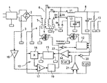
- the converter comprises as input a filter circuit 1, known in itself, connected to a rectifier circuit 2.
- the rectifier circuit 2 is also known in itself and formed here by a diode bridge having terminals of input connected to the filter circuit 1, a first output terminal connected to a current measuring shunt 3 and a second output terminal connected, on the one hand, to a divider bridge 4 and, on the other hand, to a winding primary 5 of an isolation transformer 6 in series with a switching switch T1.
- the switching switch T1 is a power transistor such as a a metal oxide-oxide field effect transistor or MOSFET (metal oxide semiconductor field effect transistor) or a bipolar transistor insulated gate or IGBT (English “insulated gate bipolar transistor").
- the switching switch T1 is connected to a control circuit or, more precisely, switching control circuit 10 which will be described below.
- the isolation transformer 6 has a first secondary winding 7 which is of identical direction to the primary winding 5 and which is connected in series to an output line 8 of the converter via a diode D3 and a filtering coil (commonly called inductance ) L1.
- a freewheeling diode D6 connects the ground to the filtering coil L1 in a manner known per se to ensure the continuity of the current when the diode D3 does not conduct (restitution of the energy by the filtering coil L1).
- the isolation transformer 6 has a second secondary winding 9 which has a direction opposite to the primary winding 5 and which is connected via a diode D2 directly to the output line 8, that is to say downstream the L1 coil.
- the CRE energy accumulation capacitor is a supercapacitor of very high capacity, of the order a few hundred farads.
- the capacity and the number of energy storage capacitors are determined according to the amount of energy which one wishes to have in case of interruption of the supply.
- the discharge switch T2 is of the same type as the switching switch T1.
- the chopper control circuit 10 is a pulse width modulation control circuit arranged to control the chopper switch T1 based on a comparison of an image voltage of a current consumed at the input of the converter with a signal. in the form of a full-wave rectified sinusoid having an amplitude dependent on an error voltage between an output voltage of the converter and a reference voltage.
- the switching control circuit 10 comprises a comparator 14 having an input connected to the divider bridge 13 connected to the output line 8 and an input connected to a reference voltage source Vref1.
- the comparator 14 has an output connected via an isolation device 15 (here an opto-electronic coupler) to a first input of a multiplier 16 having a second input connected to the divider bridge 4.
- the multiplier 16 has an output connected to a first input of a hysteresis comparator 17 having a second input connected to the measurement shunt 3 via an inverter 18 to receive an image voltage of the consumed current and an output connected via a delay 19 to a control input (the gate) of the switch T1 cutting.
- the isolation transformer 6 has a conversion ratio of 1.5.
- the principle of the converter consists in controlling, in PWM modulation, the switching switch T1 so as to force the consumed current to follow a waveform identical to that of the voltage, namely a full-wave rectified sinusoid.
- the signal from the divider bridge 4 representative of the output voltage of the rectifier circuit 2 (full-wave rectified sinusoid)
- the multiplier 16 is multiplied by the multiplier 16 with a signal representative of an error voltage resulting from the comparison.
- the product of these signals is a double-wave rectified sinusoidal signal whose amplitude depends on the error on the output voltage.
- This signal is compared, with a hysteresis, by the hysteresis comparator 17 to an image voltage of the consumed current picked up at the measurement shunt 3.
- the output signal of the hysteresis comparator 17 supplies the gate of the switching switch T1 after delay.
- the discharge switch T1 when the current is lower than the error voltage, the discharge switch T1 is on, whereas when the current is stronger than the error voltage, the switching switch T1 is off.
- the energy stored in the The magnetic core of the isolation transformer 6 excites the second secondary winding 9 and is transmitted to the output line 8 through the diode D2.
- the operation of the converter is then similar to that of a FLYBACK type converter, to ensure a power consumption, used by the output, during the low amplitude phases of the rectified sinusoidal voltage.
- the diode D3 When the output voltage has increased to a threshold equal to the product of the input voltage and the transformation ratio, the diode D3 conducts and the energy of the magnetic core is transferred to the output line by the first winding 7, the diode D3 and the filtering coil L1.
- the operation of the converter is then similar to that of a FORWARD type converter.
- the converter also then has a FLYBACK-type minority mode of operation which contributes the complete discharge of the magnetic core of the isolation transformer.
- the energy accumulation capacitor Cres is loaded (when the converter has a FORWARD mode of operation) via the third secondary winding 11 and the diode D4.
- the coupled filter coils L1 and L2 provide a limitation of the load current peaks and approximate regulation of the charging voltage.
- a disappearance of the supply voltage is detected by the discharge control circuit 12 which drives the discharge switch T2 in pulse width modulation.
- the filter coil assembly L2 and energy storage capacitor Cree then operates as a voltage booster with a resulting value slaved to the normal operating operation setpoint.
- the discharge control circuit 12 is arranged to adjust the duty ratio of its control to the charge level of the energy storage capacitor Cree.
- the energy reserve is optional.
Landscapes
- Engineering & Computer Science (AREA)
- Power Engineering (AREA)
- Dc-Dc Converters (AREA)
- Rectifiers (AREA)
Claims (7)
- Wechselstrom-/Gleichstromwandler, umfassend als Eingang eine Gleichrichterschaltung (2), die in Serie mit einer Primärwicklung (5) eines Isolationstransforlnators (6) und einem Trennschalter (T1) verbunden ist, der an einen Steuerkreis (10) zur Steuerung durch Pulsbreitenmodulation angeschlossen ist, wobei der Isolationstransformator eine erste Sekundärwicklung (7) umfasst, bei der die Wicklungsrichtung mit der jener Primärwicklung identisch ist, und die über eine Diode (D3) und eine Filterspule (L1) mit einer Ausgangsleitung (8) des Wandlers verbunden ist, wobei die Ausgangsleitung mit einem Ausgangskondensator (Cout) verbunden ist, dadurch gekennzeichnet, dass der Isolationstransformator eine zweite Sekundärwicklung (9) umfasst, bei der die Wicklungsrichtung entgegengesetzt zu jener der Primärwicklung ist, und die direkt über eine Diode (D2) mit der Ausgangsleitung (8) verbunden ist.
- Wandler nach Anspruch 1, bei dem der Steuerkreis (10) ausgebildet ist, um den Trennschalter (T1) in Abhängigkeit eines Vergleichs einer einen Verbrauchsstrom am Eingang des Wandlers abbildenden Spannung mit einem Signal in Form einer zweiweggleichgerichteten Sinuskurve zu steuern, deren Amplitude von einer Fehlerspannung (14) zwischen einer Ausgangsspannung (13) des Wandlers und einer Referenzspannung (Vref1) abhängt.
- Wandler nach Anspruch 2, bei dem der Steuerkreis (10) des Trennschalters (T1) einen Komparator (14) mit Eingängen, die mit der Ausgangsleitung (8) und einer Referenzspannungsquelle (Vréf1) verbunden sind, sowie mit einem Ausgang umfasst, der mit einem ersten Eingang eines Verstärkers (16) verbunden ist, der einen zweiten Eingang zum Aufnehmen einer Ausgangsspannung der Gleichrichterschaltung (2) und einen Ausgang aufweist, der mit einem ersten Eingang eines Hysteresekomparators (17) verbunden ist, der einen zweiten Eingang zur Aufnahme einer den verbrauchten Strom abbildenden Spannung und einen Ausgang aufweist, der über ein Verzögerungsglied (19) mit einem Steuer-Eingang des Trennschalters verbunden ist.
- Wandler nach Anspruch 1, umfassend eine Energiereserve, die eine dritte Sekundärwicklung (11) des Isolationstransformators (6) umfasst, die die gleiche Wicklungsrichtung wie die Primärwicklung (5) aufweist, und die einerseits mit einer Filterspule (L2) und einem Kondensator zur Energiespeicherung (Crés) verbunden ist, und andererseits mit der Ausgangsleitung (8) über einen Leistungsschalter (T2) verbunden ist, der durch einen Entladungs-Steuerkreis (12) gesteuert wird in Abhängigkeit eines Ladungsniveaus des Kondensators für die Energiespeicherung (Crés).
- Wandler nach Anspruch 4 in Abhängigkeit von Anspruch 3, umfassend einen Komparator (21) mit einem ersten Eingang, der eine Ausgangsspannung der Gleichrichterschaltung (2) aufnimmt, und einem zweiten Eingang, der mit einer Referenzspannungsquelle (Vref2) verbunden ist, sowie einem mit dem Entladungs-Steuerkreis (12) verbundenen Ausgang.
- Wandler nach Anspruch 5, bei dem der Entladungs-Stromkreis (12) des Weiteren folgendes aufweist:- einen Eingang, der mit der Filterspule (L2) und dem Kondensator für die Energiespeicherung (Crés) verbunden ist,- einen Eingang, der mit der Ausgangsleitung (8) verbunden ist,- einen Eingang, der über ein Inversions- und Isolierungsorgan (22) mit dem Ausgang des Verzögerungsgliedes (19) verbunden ist,- einen Ausgang, der mit dem Steuer-Eingang des Leistungsschalters (T2) verbunden ist.
- Wandler nach Anspruch 1, umfassend eine Filterschaltung (1) stromaufwärts der Gleichrichterschaltung (2).
Applications Claiming Priority (2)
| Application Number | Priority Date | Filing Date | Title |
|---|---|---|---|
| FR0708909A FR2925790B1 (fr) | 2007-12-19 | 2007-12-19 | Convertisseur alternatif/continu a isolement galvanique |
| PCT/FR2008/001710 WO2009101300A2 (fr) | 2007-12-19 | 2008-12-09 | Convertisseur alternatif/continu a isolement galvanique |
Publications (2)
| Publication Number | Publication Date |
|---|---|
| EP2232687A2 EP2232687A2 (de) | 2010-09-29 |
| EP2232687B1 true EP2232687B1 (de) | 2013-07-03 |
Family
ID=39790972
Family Applications (1)
| Application Number | Title | Priority Date | Filing Date |
|---|---|---|---|
| EP08872488.5A Active EP2232687B1 (de) | 2007-12-19 | 2008-12-09 | Wechselstrom/gleichstromwandler mit galvanischer trennung |
Country Status (8)
| Country | Link |
|---|---|
| US (1) | US8456869B2 (de) |
| EP (1) | EP2232687B1 (de) |
| CN (1) | CN101904082B (de) |
| BR (1) | BRPI0820893A2 (de) |
| CA (1) | CA2709574C (de) |
| FR (1) | FR2925790B1 (de) |
| RU (1) | RU2454780C2 (de) |
| WO (1) | WO2009101300A2 (de) |
Families Citing this family (22)
| Publication number | Priority date | Publication date | Assignee | Title |
|---|---|---|---|---|
| FR2958094B1 (fr) | 2010-03-23 | 2012-03-30 | Sagem Defense Securite | Convertisseur alternatif / continu a isolement galvanique |
| GB201102031D0 (en) * | 2011-02-07 | 2011-03-23 | Rolls Royce Plc | Protection system for an electrical power network |
| FR2975497B1 (fr) * | 2011-05-16 | 2013-06-28 | Centre Nat Rech Scient | Convertisseur electronique de puissance |
| FR2979040B1 (fr) * | 2011-08-12 | 2014-05-30 | Sagem Defense Securite | Convertisseur alternatif/continu a isolement galvanique et correcteur de signal |
| AT511709B1 (de) * | 2011-10-04 | 2013-02-15 | Hitzinger Gmbh Dipl Ing | Umformer zum anschluss des elektrischen bordnetzes eines flugzeugs an ein wechselstromnetz |
| KR102085725B1 (ko) * | 2013-02-28 | 2020-03-06 | 주식회사 실리콘웍스 | 발광 다이오드 조명 장치 및 그의 제어 방법 |
| US10340082B2 (en) | 2015-05-12 | 2019-07-02 | Capacitor Sciences Incorporated | Capacitor and method of production thereof |
| US20170301477A1 (en) | 2016-04-04 | 2017-10-19 | Capacitor Sciences Incorporated | Electro-polarizable compound and capacitor |
| US10347423B2 (en) | 2014-05-12 | 2019-07-09 | Capacitor Sciences Incorporated | Solid multilayer structure as semiproduct for meta-capacitor |
| CN110085424B (zh) | 2014-05-12 | 2021-05-18 | 柯帕瑟特科学有限责任公司 | 能量储存器件及其制造方法 |
| MX2017005427A (es) | 2014-11-04 | 2017-06-21 | Capacitor Sciences Inc | Dispositivos de almacenamiento de energia y metodos de produccion de los mismos. |
| RU2589030C1 (ru) * | 2014-12-23 | 2016-07-10 | Акционерное общество "Научно-производственное объединение автоматики имени академика Н.А. Семихатова" | Преобразователь переменного напряжения в постоянное |
| KR20170118764A (ko) | 2015-02-26 | 2017-10-25 | 캐패시터 사이언시스 인코포레이티드 | 자기-회복 커패시터 및 이들의 생산 방법 |
| US9932358B2 (en) | 2015-05-21 | 2018-04-03 | Capacitor Science Incorporated | Energy storage molecular material, crystal dielectric layer and capacitor |
| US9941051B2 (en) | 2015-06-26 | 2018-04-10 | Capactor Sciences Incorporated | Coiled capacitor |
| US10026553B2 (en) | 2015-10-21 | 2018-07-17 | Capacitor Sciences Incorporated | Organic compound, crystal dielectric layer and capacitor |
| US10305295B2 (en) | 2016-02-12 | 2019-05-28 | Capacitor Sciences Incorporated | Energy storage cell, capacitive energy storage module, and capacitive energy storage system |
| US10153087B2 (en) | 2016-04-04 | 2018-12-11 | Capacitor Sciences Incorporated | Electro-polarizable compound and capacitor |
| US9978517B2 (en) | 2016-04-04 | 2018-05-22 | Capacitor Sciences Incorporated | Electro-polarizable compound and capacitor |
| US10395841B2 (en) | 2016-12-02 | 2019-08-27 | Capacitor Sciences Incorporated | Multilayered electrode and film energy storage device |
| JP7566506B2 (ja) * | 2020-06-26 | 2024-10-15 | 旭化成エレクトロニクス株式会社 | 電力供給装置 |
| TWI885499B (zh) * | 2023-07-05 | 2025-06-01 | 財團法人工業技術研究院 | 順向式轉換器及順向式功因修正器 |
Family Cites Families (9)
| Publication number | Priority date | Publication date | Assignee | Title |
|---|---|---|---|---|
| SU1288667A1 (ru) * | 1985-04-24 | 1987-02-07 | Ивановский энергетический институт им.В.И.Ленина | Однотактный стабилизированный преобразователь |
| DE4028471A1 (de) * | 1990-09-07 | 1992-03-12 | Ant Nachrichtentech | Getaktete stromversorgungseinrichtung mit einem fluss- und einem sperrwandlerausgang |
| JPH0678542A (ja) * | 1992-08-25 | 1994-03-18 | Matsushita Electric Ind Co Ltd | 力率改善電源装置 |
| JP3263272B2 (ja) * | 1995-02-24 | 2002-03-04 | 新電元工業株式会社 | スイッチング電源装置 |
| US5973939A (en) * | 1996-08-29 | 1999-10-26 | Trw Inc. | Double forward converter with soft-PWM switching |
| US6130828A (en) * | 1999-08-26 | 2000-10-10 | Lucent Technologies, Inc. | Multiple output converter having self-synchronized pulse width modulation regulation |
| EP1477022A1 (de) * | 2002-02-23 | 2004-11-17 | Thomson Licensing S.A. | Stromversorgungseinheit mit einem schaltnetzteil |
| JP3994942B2 (ja) * | 2003-07-24 | 2007-10-24 | ソニー株式会社 | 電源回路及び電子機器 |
| TW200847602A (en) * | 2007-05-29 | 2008-12-01 | Richtek Techohnology Corp | Apparatus and method of improving flyback transformer light-loading efficacy |
-
2007
- 2007-12-19 FR FR0708909A patent/FR2925790B1/fr not_active Expired - Fee Related
-
2008
- 2008-12-09 BR BRPI0820893-0A patent/BRPI0820893A2/pt not_active IP Right Cessation
- 2008-12-09 EP EP08872488.5A patent/EP2232687B1/de active Active
- 2008-12-09 CN CN200880122231.2A patent/CN101904082B/zh active Active
- 2008-12-09 RU RU2010129693/07A patent/RU2454780C2/ru not_active IP Right Cessation
- 2008-12-09 CA CA2709574A patent/CA2709574C/fr not_active Expired - Fee Related
- 2008-12-09 WO PCT/FR2008/001710 patent/WO2009101300A2/fr not_active Ceased
- 2008-12-09 US US12/744,726 patent/US8456869B2/en active Active
Also Published As
| Publication number | Publication date |
|---|---|
| US8456869B2 (en) | 2013-06-04 |
| FR2925790A1 (fr) | 2009-06-26 |
| EP2232687A2 (de) | 2010-09-29 |
| RU2010129693A (ru) | 2012-01-27 |
| WO2009101300A3 (fr) | 2009-11-12 |
| WO2009101300A2 (fr) | 2009-08-20 |
| CN101904082B (zh) | 2013-09-04 |
| CA2709574A1 (fr) | 2009-08-20 |
| FR2925790B1 (fr) | 2010-01-15 |
| CA2709574C (fr) | 2014-02-25 |
| BRPI0820893A2 (pt) | 2015-06-16 |
| RU2454780C2 (ru) | 2012-06-27 |
| US20100309696A1 (en) | 2010-12-09 |
| CN101904082A (zh) | 2010-12-01 |
Similar Documents
| Publication | Publication Date | Title |
|---|---|---|
| EP2232687B1 (de) | Wechselstrom/gleichstromwandler mit galvanischer trennung | |
| EP2742585B1 (de) | Ac/dc-wandler mit galvanischer isolierung und signalkorrektor | |
| FR2713030A1 (fr) | Alimentation sans coupure à neutre traversant, comportant un hacheur-élévateur double. | |
| EP3075058B1 (de) | Vorrichtung zum auswuchten der last eines hochleistungsbatterieelements | |
| FR3004870A1 (fr) | Procede et dispositif de commande d'un convertisseur multiphase courant continu-courant continu a resonance, et convertisseur multiphase correspondant | |
| WO2007122268A2 (fr) | Dispositif de transfert de puissance isole perfectionne | |
| EP3010133B1 (de) | Anordnung zur kontrollierten gleichrichtung | |
| EP3389175B1 (de) | Umwandlungsvorrichtung, entsprechendes steuerverfahren und entsprechendes fahrzeug | |
| WO2010029222A1 (fr) | Dispositif convertisseur et alimentation sans interruption équipée d'un tel dispositif | |
| EP2550728B1 (de) | Gleichrichter mit galvanischer Isolierung | |
| EP2504912B1 (de) | Gleichspannungswandler fur electrische spannung mit einer electrischen gleichspannungsquelle | |
| EP3685485B1 (de) | Verfahren zur steuerung eines ladesystems einer traktionbatterie | |
| EP4290750A1 (de) | Stromversorgungsvorrichtung durch stromextraktion auf einer netzleitung | |
| FR2797723A1 (fr) | Systeme de charge de batterie, qui commande la puissance de charge en utilisant un condensateur formant un quatrieme element | |
| JP2004364493A (ja) | 電力変換装置およびその制御方法、並びに、太陽光発電装置 | |
| FR3008258A1 (fr) | Convertisseur ac/dc a isolement galvanique et correcteur de signal | |
| EP4014309B1 (de) | Induktive halteschaltung | |
| EP2297840A1 (de) | Bogenschweissungsset mit einem optimierten quasiresonanten weichumschaltungswandler | |
| WO2023110643A1 (fr) | Module de conversion comprenant un circuit de recuperation d'energie electrique | |
| EP4415238A1 (de) | Elektrisches stromversorgungsmodul | |
| FR3089709A1 (fr) | Système de gestion des interruptions électriques du réseau électrique d’un aéronef | |
| FR2600221A1 (fr) | Alimentation en courant alternatif de forte puissance non susceptible d'etre interrompue |
Legal Events
| Date | Code | Title | Description |
|---|---|---|---|
| PUAI | Public reference made under article 153(3) epc to a published international application that has entered the european phase |
Free format text: ORIGINAL CODE: 0009012 |
|
| 17P | Request for examination filed |
Effective date: 20100604 |
|
| AK | Designated contracting states |
Kind code of ref document: A2 Designated state(s): AT BE BG CH CY CZ DE DK EE ES FI FR GB GR HR HU IE IS IT LI LT LU LV MC MT NL NO PL PT RO SE SI SK TR |
|
| AX | Request for extension of the european patent |
Extension state: AL BA MK RS |
|
| DAX | Request for extension of the european patent (deleted) | ||
| GRAP | Despatch of communication of intention to grant a patent |
Free format text: ORIGINAL CODE: EPIDOSNIGR1 |
|
| RIN1 | Information on inventor provided before grant (corrected) |
Inventor name: GUILLOT, FRANCOIS Inventor name: COURTEILLE, JEAN-MARIE |
|
| GRAS | Grant fee paid |
Free format text: ORIGINAL CODE: EPIDOSNIGR3 |
|
| GRAA | (expected) grant |
Free format text: ORIGINAL CODE: 0009210 |
|
| AK | Designated contracting states |
Kind code of ref document: B1 Designated state(s): AT BE BG CH CY CZ DE DK EE ES FI FR GB GR HR HU IE IS IT LI LT LU LV MC MT NL NO PL PT RO SE SI SK TR |
|
| REG | Reference to a national code |
Ref country code: GB Ref legal event code: FG4D Free format text: NOT ENGLISH |
|
| REG | Reference to a national code |
Ref country code: AT Ref legal event code: REF Ref document number: 620231 Country of ref document: AT Kind code of ref document: T Effective date: 20130715 Ref country code: CH Ref legal event code: EP |
|
| REG | Reference to a national code |
Ref country code: IE Ref legal event code: FG4D Free format text: LANGUAGE OF EP DOCUMENT: FRENCH |
|
| REG | Reference to a national code |
Ref country code: DE Ref legal event code: R096 Ref document number: 602008025844 Country of ref document: DE Effective date: 20130829 |
|
| PG25 | Lapsed in a contracting state [announced via postgrant information from national office to epo] |
Ref country code: SI Free format text: LAPSE BECAUSE OF FAILURE TO SUBMIT A TRANSLATION OF THE DESCRIPTION OR TO PAY THE FEE WITHIN THE PRESCRIBED TIME-LIMIT Effective date: 20130703 |
|
| REG | Reference to a national code |
Ref country code: AT Ref legal event code: MK05 Ref document number: 620231 Country of ref document: AT Kind code of ref document: T Effective date: 20130703 |
|
| REG | Reference to a national code |
Ref country code: NL Ref legal event code: VDEP Effective date: 20130703 |
|
| REG | Reference to a national code |
Ref country code: LT Ref legal event code: MG4D |
|
| RAP2 | Party data changed (patent owner data changed or rights of a patent transferred) |
Owner name: SAGEM DEFENSE SECURITE |
|
| PG25 | Lapsed in a contracting state [announced via postgrant information from national office to epo] |
Ref country code: PT Free format text: LAPSE BECAUSE OF FAILURE TO SUBMIT A TRANSLATION OF THE DESCRIPTION OR TO PAY THE FEE WITHIN THE PRESCRIBED TIME-LIMIT Effective date: 20131104 Ref country code: LT Free format text: LAPSE BECAUSE OF FAILURE TO SUBMIT A TRANSLATION OF THE DESCRIPTION OR TO PAY THE FEE WITHIN THE PRESCRIBED TIME-LIMIT Effective date: 20130703 Ref country code: CY Free format text: LAPSE BECAUSE OF FAILURE TO SUBMIT A TRANSLATION OF THE DESCRIPTION OR TO PAY THE FEE WITHIN THE PRESCRIBED TIME-LIMIT Effective date: 20130904 Ref country code: NO Free format text: LAPSE BECAUSE OF FAILURE TO SUBMIT A TRANSLATION OF THE DESCRIPTION OR TO PAY THE FEE WITHIN THE PRESCRIBED TIME-LIMIT Effective date: 20131003 Ref country code: SE Free format text: LAPSE BECAUSE OF FAILURE TO SUBMIT A TRANSLATION OF THE DESCRIPTION OR TO PAY THE FEE WITHIN THE PRESCRIBED TIME-LIMIT Effective date: 20130703 Ref country code: IS Free format text: LAPSE BECAUSE OF FAILURE TO SUBMIT A TRANSLATION OF THE DESCRIPTION OR TO PAY THE FEE WITHIN THE PRESCRIBED TIME-LIMIT Effective date: 20131103 Ref country code: HR Free format text: LAPSE BECAUSE OF FAILURE TO SUBMIT A TRANSLATION OF THE DESCRIPTION OR TO PAY THE FEE WITHIN THE PRESCRIBED TIME-LIMIT Effective date: 20130703 Ref country code: AT Free format text: LAPSE BECAUSE OF FAILURE TO SUBMIT A TRANSLATION OF THE DESCRIPTION OR TO PAY THE FEE WITHIN THE PRESCRIBED TIME-LIMIT Effective date: 20130703 |
|
| PG25 | Lapsed in a contracting state [announced via postgrant information from national office to epo] |
Ref country code: PL Free format text: LAPSE BECAUSE OF FAILURE TO SUBMIT A TRANSLATION OF THE DESCRIPTION OR TO PAY THE FEE WITHIN THE PRESCRIBED TIME-LIMIT Effective date: 20130703 Ref country code: NL Free format text: LAPSE BECAUSE OF FAILURE TO SUBMIT A TRANSLATION OF THE DESCRIPTION OR TO PAY THE FEE WITHIN THE PRESCRIBED TIME-LIMIT Effective date: 20130703 Ref country code: GR Free format text: LAPSE BECAUSE OF FAILURE TO SUBMIT A TRANSLATION OF THE DESCRIPTION OR TO PAY THE FEE WITHIN THE PRESCRIBED TIME-LIMIT Effective date: 20131004 Ref country code: LV Free format text: LAPSE BECAUSE OF FAILURE TO SUBMIT A TRANSLATION OF THE DESCRIPTION OR TO PAY THE FEE WITHIN THE PRESCRIBED TIME-LIMIT Effective date: 20130703 Ref country code: ES Free format text: LAPSE BECAUSE OF FAILURE TO SUBMIT A TRANSLATION OF THE DESCRIPTION OR TO PAY THE FEE WITHIN THE PRESCRIBED TIME-LIMIT Effective date: 20131014 Ref country code: FI Free format text: LAPSE BECAUSE OF FAILURE TO SUBMIT A TRANSLATION OF THE DESCRIPTION OR TO PAY THE FEE WITHIN THE PRESCRIBED TIME-LIMIT Effective date: 20130703 |
|
| PG25 | Lapsed in a contracting state [announced via postgrant information from national office to epo] |
Ref country code: CY Free format text: LAPSE BECAUSE OF FAILURE TO SUBMIT A TRANSLATION OF THE DESCRIPTION OR TO PAY THE FEE WITHIN THE PRESCRIBED TIME-LIMIT Effective date: 20130703 |
|
| PG25 | Lapsed in a contracting state [announced via postgrant information from national office to epo] |
Ref country code: RO Free format text: LAPSE BECAUSE OF FAILURE TO SUBMIT A TRANSLATION OF THE DESCRIPTION OR TO PAY THE FEE WITHIN THE PRESCRIBED TIME-LIMIT Effective date: 20130703 Ref country code: EE Free format text: LAPSE BECAUSE OF FAILURE TO SUBMIT A TRANSLATION OF THE DESCRIPTION OR TO PAY THE FEE WITHIN THE PRESCRIBED TIME-LIMIT Effective date: 20130703 Ref country code: SK Free format text: LAPSE BECAUSE OF FAILURE TO SUBMIT A TRANSLATION OF THE DESCRIPTION OR TO PAY THE FEE WITHIN THE PRESCRIBED TIME-LIMIT Effective date: 20130703 Ref country code: CZ Free format text: LAPSE BECAUSE OF FAILURE TO SUBMIT A TRANSLATION OF THE DESCRIPTION OR TO PAY THE FEE WITHIN THE PRESCRIBED TIME-LIMIT Effective date: 20130703 Ref country code: DK Free format text: LAPSE BECAUSE OF FAILURE TO SUBMIT A TRANSLATION OF THE DESCRIPTION OR TO PAY THE FEE WITHIN THE PRESCRIBED TIME-LIMIT Effective date: 20130703 |
|
| PLBE | No opposition filed within time limit |
Free format text: ORIGINAL CODE: 0009261 |
|
| STAA | Information on the status of an ep patent application or granted ep patent |
Free format text: STATUS: NO OPPOSITION FILED WITHIN TIME LIMIT |
|
| PG25 | Lapsed in a contracting state [announced via postgrant information from national office to epo] |
Ref country code: IT Free format text: LAPSE BECAUSE OF FAILURE TO SUBMIT A TRANSLATION OF THE DESCRIPTION OR TO PAY THE FEE WITHIN THE PRESCRIBED TIME-LIMIT Effective date: 20130703 |
|
| 26N | No opposition filed |
Effective date: 20140404 |
|
| BERE | Be: lapsed |
Owner name: SAGEM DEFENSE SECURITE Effective date: 20131231 |
|
| REG | Reference to a national code |
Ref country code: DE Ref legal event code: R097 Ref document number: 602008025844 Country of ref document: DE Effective date: 20140404 |
|
| REG | Reference to a national code |
Ref country code: CH Ref legal event code: PL |
|
| PG25 | Lapsed in a contracting state [announced via postgrant information from national office to epo] |
Ref country code: LU Free format text: LAPSE BECAUSE OF FAILURE TO SUBMIT A TRANSLATION OF THE DESCRIPTION OR TO PAY THE FEE WITHIN THE PRESCRIBED TIME-LIMIT Effective date: 20131209 Ref country code: MC Free format text: LAPSE BECAUSE OF FAILURE TO SUBMIT A TRANSLATION OF THE DESCRIPTION OR TO PAY THE FEE WITHIN THE PRESCRIBED TIME-LIMIT Effective date: 20130703 |
|
| REG | Reference to a national code |
Ref country code: IE Ref legal event code: MM4A |
|
| PG25 | Lapsed in a contracting state [announced via postgrant information from national office to epo] |
Ref country code: CH Free format text: LAPSE BECAUSE OF NON-PAYMENT OF DUE FEES Effective date: 20131231 Ref country code: IE Free format text: LAPSE BECAUSE OF NON-PAYMENT OF DUE FEES Effective date: 20131209 Ref country code: LI Free format text: LAPSE BECAUSE OF NON-PAYMENT OF DUE FEES Effective date: 20131231 Ref country code: BE Free format text: LAPSE BECAUSE OF NON-PAYMENT OF DUE FEES Effective date: 20131231 |
|
| PG25 | Lapsed in a contracting state [announced via postgrant information from national office to epo] |
Ref country code: TR Free format text: LAPSE BECAUSE OF FAILURE TO SUBMIT A TRANSLATION OF THE DESCRIPTION OR TO PAY THE FEE WITHIN THE PRESCRIBED TIME-LIMIT Effective date: 20130703 |
|
| PG25 | Lapsed in a contracting state [announced via postgrant information from national office to epo] |
Ref country code: HU Free format text: LAPSE BECAUSE OF FAILURE TO SUBMIT A TRANSLATION OF THE DESCRIPTION OR TO PAY THE FEE WITHIN THE PRESCRIBED TIME-LIMIT; INVALID AB INITIO Effective date: 20081209 Ref country code: BG Free format text: LAPSE BECAUSE OF FAILURE TO SUBMIT A TRANSLATION OF THE DESCRIPTION OR TO PAY THE FEE WITHIN THE PRESCRIBED TIME-LIMIT Effective date: 20130703 |
|
| PG25 | Lapsed in a contracting state [announced via postgrant information from national office to epo] |
Ref country code: MT Free format text: LAPSE BECAUSE OF FAILURE TO SUBMIT A TRANSLATION OF THE DESCRIPTION OR TO PAY THE FEE WITHIN THE PRESCRIBED TIME-LIMIT Effective date: 20130703 |
|
| REG | Reference to a national code |
Ref country code: FR Ref legal event code: PLFP Year of fee payment: 8 |
|
| REG | Reference to a national code |
Ref country code: FR Ref legal event code: PLFP Year of fee payment: 9 |
|
| REG | Reference to a national code |
Ref country code: FR Ref legal event code: CD Owner name: SAFRAN ELECTRONICS & DEFENSE, FR Effective date: 20170111 |
|
| REG | Reference to a national code |
Ref country code: FR Ref legal event code: PLFP Year of fee payment: 10 |
|
| PGFP | Annual fee paid to national office [announced via postgrant information from national office to epo] |
Ref country code: GB Payment date: 20251229 Year of fee payment: 18 |
|
| PGFP | Annual fee paid to national office [announced via postgrant information from national office to epo] |
Ref country code: FR Payment date: 20251222 Year of fee payment: 18 |
|
| PGFP | Annual fee paid to national office [announced via postgrant information from national office to epo] |
Ref country code: DE Payment date: 20251222 Year of fee payment: 18 |