EP2231389B1 - Mehrschichtiger textilschutzstoff und verfahren zu seiner herstellung - Google Patents
Mehrschichtiger textilschutzstoff und verfahren zu seiner herstellung Download PDFInfo
- Publication number
- EP2231389B1 EP2231389B1 EP20090701023 EP09701023A EP2231389B1 EP 2231389 B1 EP2231389 B1 EP 2231389B1 EP 20090701023 EP20090701023 EP 20090701023 EP 09701023 A EP09701023 A EP 09701023A EP 2231389 B1 EP2231389 B1 EP 2231389B1
- Authority
- EP
- European Patent Office
- Prior art keywords
- sleeve
- yarn
- layer
- layers
- length direction
- Prior art date
- Legal status (The legal status is an assumption and is not a legal conclusion. Google has not performed a legal analysis and makes no representation as to the accuracy of the status listed.)
- Active
Links
Images





Classifications
-
- B—PERFORMING OPERATIONS; TRANSPORTING
- B32—LAYERED PRODUCTS
- B32B—LAYERED PRODUCTS, i.e. PRODUCTS BUILT-UP OF STRATA OF FLAT OR NON-FLAT, e.g. CELLULAR OR HONEYCOMB, FORM
- B32B1/00—Layered products having a non-planar shape
- B32B1/08—Tubular products
-
- B—PERFORMING OPERATIONS; TRANSPORTING
- B32—LAYERED PRODUCTS
- B32B—LAYERED PRODUCTS, i.e. PRODUCTS BUILT-UP OF STRATA OF FLAT OR NON-FLAT, e.g. CELLULAR OR HONEYCOMB, FORM
- B32B3/00—Layered products comprising a layer with external or internal discontinuities or unevennesses, or a layer of non-planar shape; Layered products comprising a layer having particular features of form
- B32B3/10—Layered products comprising a layer with external or internal discontinuities or unevennesses, or a layer of non-planar shape; Layered products comprising a layer having particular features of form characterised by a discontinuous layer, i.e. formed of separate pieces of material
-
- B—PERFORMING OPERATIONS; TRANSPORTING
- B32—LAYERED PRODUCTS
- B32B—LAYERED PRODUCTS, i.e. PRODUCTS BUILT-UP OF STRATA OF FLAT OR NON-FLAT, e.g. CELLULAR OR HONEYCOMB, FORM
- B32B5/00—Layered products characterised by the non- homogeneity or physical structure, i.e. comprising a fibrous, filamentary, particulate or foam layer; Layered products characterised by having a layer differing constitutionally or physically in different parts
- B32B5/02—Layered products characterised by the non- homogeneity or physical structure, i.e. comprising a fibrous, filamentary, particulate or foam layer; Layered products characterised by having a layer differing constitutionally or physically in different parts characterised by structural features of a fibrous or filamentary layer
-
- B—PERFORMING OPERATIONS; TRANSPORTING
- B32—LAYERED PRODUCTS
- B32B—LAYERED PRODUCTS, i.e. PRODUCTS BUILT-UP OF STRATA OF FLAT OR NON-FLAT, e.g. CELLULAR OR HONEYCOMB, FORM
- B32B5/00—Layered products characterised by the non- homogeneity or physical structure, i.e. comprising a fibrous, filamentary, particulate or foam layer; Layered products characterised by having a layer differing constitutionally or physically in different parts
- B32B5/02—Layered products characterised by the non- homogeneity or physical structure, i.e. comprising a fibrous, filamentary, particulate or foam layer; Layered products characterised by having a layer differing constitutionally or physically in different parts characterised by structural features of a fibrous or filamentary layer
- B32B5/026—Knitted fabric
-
- B—PERFORMING OPERATIONS; TRANSPORTING
- B32—LAYERED PRODUCTS
- B32B—LAYERED PRODUCTS, i.e. PRODUCTS BUILT-UP OF STRATA OF FLAT OR NON-FLAT, e.g. CELLULAR OR HONEYCOMB, FORM
- B32B5/00—Layered products characterised by the non- homogeneity or physical structure, i.e. comprising a fibrous, filamentary, particulate or foam layer; Layered products characterised by having a layer differing constitutionally or physically in different parts
- B32B5/02—Layered products characterised by the non- homogeneity or physical structure, i.e. comprising a fibrous, filamentary, particulate or foam layer; Layered products characterised by having a layer differing constitutionally or physically in different parts characterised by structural features of a fibrous or filamentary layer
- B32B5/08—Layered products characterised by the non- homogeneity or physical structure, i.e. comprising a fibrous, filamentary, particulate or foam layer; Layered products characterised by having a layer differing constitutionally or physically in different parts characterised by structural features of a fibrous or filamentary layer the fibres or filaments of a layer being of different substances, e.g. conjugate fibres, mixture of different fibres
-
- B—PERFORMING OPERATIONS; TRANSPORTING
- B32—LAYERED PRODUCTS
- B32B—LAYERED PRODUCTS, i.e. PRODUCTS BUILT-UP OF STRATA OF FLAT OR NON-FLAT, e.g. CELLULAR OR HONEYCOMB, FORM
- B32B5/00—Layered products characterised by the non- homogeneity or physical structure, i.e. comprising a fibrous, filamentary, particulate or foam layer; Layered products characterised by having a layer differing constitutionally or physically in different parts
- B32B5/02—Layered products characterised by the non- homogeneity or physical structure, i.e. comprising a fibrous, filamentary, particulate or foam layer; Layered products characterised by having a layer differing constitutionally or physically in different parts characterised by structural features of a fibrous or filamentary layer
- B32B5/12—Layered products characterised by the non- homogeneity or physical structure, i.e. comprising a fibrous, filamentary, particulate or foam layer; Layered products characterised by having a layer differing constitutionally or physically in different parts characterised by structural features of a fibrous or filamentary layer characterised by the relative arrangement of fibres or filaments of different layers, e.g. the fibres or filaments being parallel or perpendicular to each other
-
- B—PERFORMING OPERATIONS; TRANSPORTING
- B32—LAYERED PRODUCTS
- B32B—LAYERED PRODUCTS, i.e. PRODUCTS BUILT-UP OF STRATA OF FLAT OR NON-FLAT, e.g. CELLULAR OR HONEYCOMB, FORM
- B32B5/00—Layered products characterised by the non- homogeneity or physical structure, i.e. comprising a fibrous, filamentary, particulate or foam layer; Layered products characterised by having a layer differing constitutionally or physically in different parts
- B32B5/14—Layered products characterised by the non- homogeneity or physical structure, i.e. comprising a fibrous, filamentary, particulate or foam layer; Layered products characterised by having a layer differing constitutionally or physically in different parts characterised by a layer differing constitutionally or physically in different parts, e.g. denser near its faces
-
- B—PERFORMING OPERATIONS; TRANSPORTING
- B32—LAYERED PRODUCTS
- B32B—LAYERED PRODUCTS, i.e. PRODUCTS BUILT-UP OF STRATA OF FLAT OR NON-FLAT, e.g. CELLULAR OR HONEYCOMB, FORM
- B32B5/00—Layered products characterised by the non- homogeneity or physical structure, i.e. comprising a fibrous, filamentary, particulate or foam layer; Layered products characterised by having a layer differing constitutionally or physically in different parts
- B32B5/22—Layered products characterised by the non- homogeneity or physical structure, i.e. comprising a fibrous, filamentary, particulate or foam layer; Layered products characterised by having a layer differing constitutionally or physically in different parts characterised by the presence of two or more layers which are next to each other and are fibrous, filamentary, formed of particles or foamed
- B32B5/24—Layered products characterised by the non- homogeneity or physical structure, i.e. comprising a fibrous, filamentary, particulate or foam layer; Layered products characterised by having a layer differing constitutionally or physically in different parts characterised by the presence of two or more layers which are next to each other and are fibrous, filamentary, formed of particles or foamed one layer being a fibrous or filamentary layer
- B32B5/26—Layered products characterised by the non- homogeneity or physical structure, i.e. comprising a fibrous, filamentary, particulate or foam layer; Layered products characterised by having a layer differing constitutionally or physically in different parts characterised by the presence of two or more layers which are next to each other and are fibrous, filamentary, formed of particles or foamed one layer being a fibrous or filamentary layer another layer next to it also being fibrous or filamentary
-
- D—TEXTILES; PAPER
- D03—WEAVING
- D03D—WOVEN FABRICS; METHODS OF WEAVING; LOOMS
- D03D1/00—Woven fabrics designed to make specified articles
- D03D1/0035—Protective fabrics
- D03D1/0043—Protective fabrics for elongated members, i.e. sleeves
-
- H—ELECTRICITY
- H02—GENERATION; CONVERSION OR DISTRIBUTION OF ELECTRIC POWER
- H02G—INSTALLATION OF ELECTRIC CABLES OR LINES, OR OF COMBINED OPTICAL AND ELECTRIC CABLES OR LINES
- H02G3/00—Installations of electric cables or lines or protective tubing therefor in or on buildings, equivalent structures or vehicles
- H02G3/02—Details
- H02G3/04—Protective tubing or conduits, e.g. cable ladders or cable troughs
- H02G3/0462—Tubings, i.e. having a closed section
- H02G3/0481—Tubings, i.e. having a closed section with a circular cross-section
-
- B—PERFORMING OPERATIONS; TRANSPORTING
- B32—LAYERED PRODUCTS
- B32B—LAYERED PRODUCTS, i.e. PRODUCTS BUILT-UP OF STRATA OF FLAT OR NON-FLAT, e.g. CELLULAR OR HONEYCOMB, FORM
- B32B2250/00—Layers arrangement
- B32B2250/20—All layers being fibrous or filamentary
-
- B—PERFORMING OPERATIONS; TRANSPORTING
- B32—LAYERED PRODUCTS
- B32B—LAYERED PRODUCTS, i.e. PRODUCTS BUILT-UP OF STRATA OF FLAT OR NON-FLAT, e.g. CELLULAR OR HONEYCOMB, FORM
- B32B2255/00—Coating on the layer surface
- B32B2255/02—Coating on the layer surface on fibrous or filamentary layer
-
- B—PERFORMING OPERATIONS; TRANSPORTING
- B32—LAYERED PRODUCTS
- B32B—LAYERED PRODUCTS, i.e. PRODUCTS BUILT-UP OF STRATA OF FLAT OR NON-FLAT, e.g. CELLULAR OR HONEYCOMB, FORM
- B32B2255/00—Coating on the layer surface
- B32B2255/20—Inorganic coating
- B32B2255/205—Metallic coating
-
- B—PERFORMING OPERATIONS; TRANSPORTING
- B32—LAYERED PRODUCTS
- B32B—LAYERED PRODUCTS, i.e. PRODUCTS BUILT-UP OF STRATA OF FLAT OR NON-FLAT, e.g. CELLULAR OR HONEYCOMB, FORM
- B32B2307/00—Properties of the layers or laminate
- B32B2307/20—Properties of the layers or laminate having particular electrical or magnetic properties, e.g. piezoelectric
- B32B2307/202—Conductive
-
- B—PERFORMING OPERATIONS; TRANSPORTING
- B32—LAYERED PRODUCTS
- B32B—LAYERED PRODUCTS, i.e. PRODUCTS BUILT-UP OF STRATA OF FLAT OR NON-FLAT, e.g. CELLULAR OR HONEYCOMB, FORM
- B32B2307/00—Properties of the layers or laminate
- B32B2307/20—Properties of the layers or laminate having particular electrical or magnetic properties, e.g. piezoelectric
- B32B2307/206—Insulating
-
- B—PERFORMING OPERATIONS; TRANSPORTING
- B32—LAYERED PRODUCTS
- B32B—LAYERED PRODUCTS, i.e. PRODUCTS BUILT-UP OF STRATA OF FLAT OR NON-FLAT, e.g. CELLULAR OR HONEYCOMB, FORM
- B32B2307/00—Properties of the layers or laminate
- B32B2307/50—Properties of the layers or laminate having particular mechanical properties
- B32B2307/554—Wear resistance
-
- B—PERFORMING OPERATIONS; TRANSPORTING
- B32—LAYERED PRODUCTS
- B32B—LAYERED PRODUCTS, i.e. PRODUCTS BUILT-UP OF STRATA OF FLAT OR NON-FLAT, e.g. CELLULAR OR HONEYCOMB, FORM
- B32B2437/00—Clothing
-
- B—PERFORMING OPERATIONS; TRANSPORTING
- B32—LAYERED PRODUCTS
- B32B—LAYERED PRODUCTS, i.e. PRODUCTS BUILT-UP OF STRATA OF FLAT OR NON-FLAT, e.g. CELLULAR OR HONEYCOMB, FORM
- B32B2571/00—Protective equipment
-
- Y—GENERAL TAGGING OF NEW TECHNOLOGICAL DEVELOPMENTS; GENERAL TAGGING OF CROSS-SECTIONAL TECHNOLOGIES SPANNING OVER SEVERAL SECTIONS OF THE IPC; TECHNICAL SUBJECTS COVERED BY FORMER USPC CROSS-REFERENCE ART COLLECTIONS [XRACs] AND DIGESTS
- Y10—TECHNICAL SUBJECTS COVERED BY FORMER USPC
- Y10T—TECHNICAL SUBJECTS COVERED BY FORMER US CLASSIFICATION
- Y10T428/00—Stock material or miscellaneous articles
- Y10T428/13—Hollow or container type article [e.g., tube, vase, etc.]
- Y10T428/1352—Polymer or resin containing [i.e., natural or synthetic]
- Y10T428/1362—Textile, fabric, cloth, or pile containing [e.g., web, net, woven, knitted, mesh, nonwoven, matted, etc.]
Definitions
- This invention relates generally to protective textile sleeves, and more particularly to multilayer textile sleeves and their method of construction.
- a multilayer textile material having a first layer constructed at least in part from one type of yarn and a second layer overlapped at least in part by the first layer, wherein the second layer is constructed at least in part from a second type of yarn that is different from the yarn used to construct the first layer.
- the first and second layers are integrally connected to one another in the process used to construct the first and second layers.
- weft yarns in the first layer hook warp yarns in the second layer, and weft yarns in the second layer hook warp yarns in the first layer to interlock the first and second layers to one another.
- the first and/or second layers have at least some warp yarns with different physical properties.
- the multilayer material has a third layer overlapped at least in part by the first and second layers, wherein the third layer is constructed in a single process with the first and second layers.
- the third layer has at least some warp yarns with different physical properties from the first and/or second layers.
- the multilayer material is formed into a protective tubular sleeve.
- At least one of the first, second or third layers provides the tubular sleeve with a circumferentially continuous conductive layer.
- the first and second or second and third layers are formed as a continuous tubular wall with the remaining layer extending outwardly from the tubular wall to a free end.
- the multilayer material has a fourth layer overlapped at least in part by the first, second and third layers, wherein the fourth layer is constructed in a single process with the first, second and third layers.
- the first and second layers are formed as a first continuous tubular wall and the third and fourth layers are formed as a second continuous tubular wall, wherein the first and second tubular walls are constructed in a single process.
- the first and second tubular walls provide a tubular sleeve having a dual layered wall.
- the first and second tubular walls provide a tubular sleeve having a four layered wall.
- a method of constructing a multilayer textile sleeve comprises weaving an outer layer having a first warp yarn extending along a length direction of the sleeve and a weft yarn extending substantially transversely to the length direction; weaving an inner layer having a second warp yarn extending along the length direction of the sleeve and a weft yarn extending substantially transversely to the length direction, and providing the second warp yarn as a different type of yarn than the first warp yarn, and connecting the outer layer and the inner layer to one another by interlinking the weft yarn of the outer layer with at least some of the second warp yarns of the inner layer and by interlinking the weft yarn of the inner layer with at least some of the first warp yarns of the outer layer.
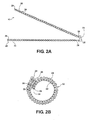
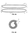
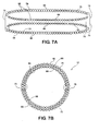
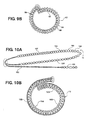
- Figures 1A-10A illustrate diagrammatically various textile materials 10 constructed in accordance with different embodiments of the invention, wherein Figures 1B-10B illustrate the respective materials 10 formed into protective sleeves 12.
- Each of the textile materials 10 is constructed having overlapping layers of yarn, wherein at least a portion of one of the layers is constructed with a different yarn type than the overlapped layer.
- the different yarns types are designated by "X" and "O".
- the yarns are selected for each of the material layers to provide the material 10 and sleeves 12 formed therewith with the desired properties, depending on their intended application of use.
- the different yarns are interlinked, such as by being woven with one another in a continuous, single weaving process, such that secondary operations are not needed to join the overlapping layers to one another.
- One weaving process contemplated herein for constructing the materials 10 is a dual pick insertion process, although other weaving processes are contemplated herein that provide a similar material in a single process.
- the material 10 is constructed having two generally equal length layers overlapping one another, with one layer being an inner layer 14 and the other being an outer layer 16.
- the layers 14, 16 are attached directly to one another generally along respective connection edges 17, 19 along a line 15 extending along a length of the material 10.
- the mechanism attaching the layers 14, 16 to one another is provided in the continuous weaving process in which the layers are woven, thereby negating the need for any secondary operations to attach the layers 14, 16 to one another.
- Each of the layers 14, 16 has warp-wise extending yarns 18, which extend along the length of the sleeve 12 (in and out of the page as shown in Figures 1-10 ), and weft-wise or fill yarns 20, which extend along the width of the sleeve 12 and thus, substantially transverse to the length of the sleeve 12.
- Each of the layers 14, 16 is represented here as being constructed with different types of warp yarns 18, either monofilament or multifilament, with one layer forming the inner layer 14 and the other layer forming the outer layer 16.
- the warp yarns 18 (designated by "X", representing one type of yarn) in the inner layer 14 are provided as a non-abrasive, slick and insulative yarns so as to provide insulation to wires or other elongate members with a cavity of the sleeve 12, while also allowing the elongate members to be easily installed within the cavity without causing damage to the elongate members.
- the warp yarns 18 (designated by "O", representing another type of yarn different from the "X” type of yarn) in the outer layer 16 are provided having any suitable color, for appearance purposes, and having high abrasion resistance and insulative properties to protect the elongate members within the cavity of the sleeve 12.
- the weft yarns 20 can be provided having any desired properties in each of the layers 14, 16, as desired.
- the weft yarns 20 can be provided of any heat settable monofilament, such as PET, for example.
- At least some of the weft filaments 20 of the inner layer 14 are interlocked or interlinked with at least some of the warp yarns 18 of the outer layer 16, and at least some of the weft yarns 20 of the outer layer 16 are interlocked or interlinked with at least some of the warp yarns 18 of the inner layer 14 to interlock the connection edges 17, 19 with one another and to provide the material 10 as a unitary, single piece member in a single manufacturing process.
- the material 10, preferably having heat formable weft yarns 20, can be heat formed or set in a heat-setting process into the desired, substantially closed tubular sleeve shape, wherein the inner layer 14 preferably overlaps the outer layer 16 in a so called "cigarette wrap" form to circumferentially enclose the elongate members within the cavity of the sleeve 12.
- the sleeve 12 is an open-type sleeve, which means the sleeve 12 is not constructed having a circumferentially closed wall, but rather, has overlapping free edges 29 extending along the length of the sleeve 12 that can be biased away from one another into an open configuration allowing access to the cavity of the sleeve.
- fasteners could be provided along a longitudinal seam of the sleeve, such as a hook and loop fastener, for example, thereby allowing the material to be manually wrapped in use and fastened about the elongate members.
- FIG. 2A and 2B another material 10 and sleeve 12 is shown constructed according to another embodiment of the invention.
- the material 10 has an inner layer 22 and an outer layer 24, wherein each of the respective layers 22, 24 has warp-wise extending yarns 26 and weft-wise or fill yarns 28.
- the warp yarns 26 (designated by "X”, representing one type of yarn) of the inner layer 22 are provided as conductive yarns to provide EMI protection to the elongate members within the cavity of the sleeve 12, while at least some of the warp yarns 26 (designated by "O", representing a different type of yarn than that designated by "X") of the outer layer 24 are provided as different types of yarns.
- the warp yarns 26 (designated by "X") adjacent the free end 29 of the outer layer 24 can be provided as conductive yarns, and can be the same type as used in the inner layer 22, while the remaining warp yarns 26 (designated by "O") of the outer layer 24 are provided having any suitable color, for appearance purposes, and having high abrasion resistance and insulative properties to protect the elongate members within the cavity of the sleeve 12.
- the conductive warp yarns 26 ("X") of the outer layer 24 adjacent the free edge 29 are brought into engagement with the conductive warp yarns 26 ("X") of the inner layer 22 to provide a complete, circumferential conductive layer or inner wall about the elongate members within the cavity of the sleeve 12.
- the remaining non-conductive warp yarns 26 ("O") of the outer layer 24 extend completely circumferentially about the outer surface of the sleeve 12 to provide an outer wall having abrasion resistance and insulative properties to the sleeve 12.
- FIG. 3A and 3B another material 10 and sleeve 12 is shown constructed according to another embodiment of the invention.
- the material 10 has an inner layer 30 and an outer layer 32, wherein each of the respective layers 30, 32 has warp-wise extending yarns 34 and weft-wise or fill yarns 36.
- the inner and outer layers 30, 32 are constructed similarly as described above in connection with the inner and outer layers 14, 16, however, the inner layer 30 is constructed having an increased width extending along a direction transverse to the length of the sleeve 12 relative to the outer layer 32.
- the warp yarns 34 of the inner layer 30 are provided as conductive yarns ("X"), whether coated with metal or in wire filament form, while the warp yarns 34 of the outer layer 32 are provided as non-conductive warp yarns ("O"). Accordingly, upon being cigarette wrapped, the inner layer 30 extends completely circumferentially into electrical communication with itself to provide complete EMI protection circumferentially about the elongate members within the sleeve 12. Meanwhile, the outer layer 32 preferably extends completely circumferentially about the inner conductive yarns ("X”) to provide complete abrasion resistance and insulative properties to the inner conductive yarns and elongate members being protected within the sleeve 12.
- FIG. 4A and 4B another material 10 and sleeve 12 is shown constructed according to another embodiment of the invention.
- the material 10 has an inner layer 38 and an outer layer 40, wherein each of the respective layers 38, 40 has warp-wise extending yarns 42 and weft-wise or fill yarns 44.
- Both the inner and outer layers 38, 40 are woven as a tubular configurations.
- the tubular inner layer 38 is attached to the tubular outer layer 40 via the weft yarns 44 in each the inner and outer layers 38, 40 being hooked or linked about respective warp yarns 42 extending along the length of the inner and outer layers.
- the tubular inner layer 38 is represented as being woven with electrically conductive warp yarns 42 ("X"), while the tubular outer layer is woven with abrasion resistant, insulative warp yarns 42 ("O”), as discussed above.
- the inner and outer layers 38, 40 provide a wall having four discrete layers. Two of the layers of the sleeve wall are formed from the inner layer 38 and two of the layers are formed from the outer layer 40.
- FIG. 5A and 5B another material 10 and sleeve 12 is shown constructed according to another embodiment of the invention.
- the material 10 has an inner layer 46 and an outer layer 48, wherein each of the respective layers 46, 48 has warp-wise extending yarns 50 and weft-wise or fill yarns 52.
- the inner and outer layers 46, 48 are formed similarly as described above in connection with Figures 4A, 4B , however, at least one or both layers 46, 48 are formed with their respective warp yarns 50 being of different types.
- the tubular inner layer 46 can have its innermost layer 47 formed with non-abrasive, electrically conductive yarns ("X"), while the outermost layer 49 of the inner layer 46 can be formed with different electrically conductive yarns ("--”) or otherwise, as desired.
- the tubular outer layer 48 can be formed with an innermost layer 51 of non-abrasive, electrically conductive yarns ("X") or otherwise, as desired, while the outermost layer 53 of the outer layer 48 can be formed with abrasion resistant, colored, insulative yarns ("O"), as described above.
- FIG. 6A and 6B another material 10 and sleeve 12 is shown constructed according to another embodiment of the invention.
- the material 10 has an inner layer 54 and an outer layer 56, wherein each of the respective layers 54, 56 has warp-wise extending yarns 58 and weft-wise or fill yarns 60.
- the inner layer 54 is formed by inner-most portions of two separate tubular sections 61, 63
- the outer layer 56 is formed by outer-most portions of the tubular sections 61, 63.
- the tubular sections 61, 63 are joined at diametrically opposite sides by weft yarns 60 looping about warp yarns 58, as discussed above.
- the tubular sections 61, 63 are moved outwardly from one another to form the inner cavity of the sleeve 12.
- the tubular section 61 is illustrated as being formed with one type of warp yarns, such as abrasion resistant, insulative yarns ("X"), while the other tubular section 63 is illustrated as being formed with another type of warp yarns, such as non-abrasive, slick and insulative yarns ("O"), for example.
- the inner layer 56 is provided both abrasion resistant, insulative warp yarns ("X") and non-abrasive, slick and insulative warp yarns ("O").
- FIG. 7A and 7B another material 10 and sleeve 12 is shown constructed according to another embodiment of the invention.
- the material 10 has an inner layer 64 and an outer layer 66, wherein each of the respective layers 64, 66 has warp-wise extending yarns 68 and weft-wise or fill yarns 70.
- the inner layer 64 is formed by inner-most portions of two separate tubular sections 71, 73 and the outer layer 66 is formed by outer-most portions of the tubular sections 71, 73.
- the tubular sections 71, 73 are joined at diametrically opposite sides by selected weft yarns 70 looping about selected warp yarns 68, as discussed above.
- the tubular sections 71, 73 are moved outwardly from one another to form the inner cavity of the sleeve 12.
- the tubular sections 71, 73 are each illustrated as being formed with two types of warp yarns, such as abrasion resistant, insulative yarns ("O"), and non-abrasive, slick and insulative yarns ("X”), for example.
- abrasion resistant, insulative yarns such as abrasion resistant, insulative yarns (“O")
- X non-abrasive, slick and insulative yarns
- FIG. 8A and 8B another material 10 and sleeve 12 is shown constructed according to another embodiment of the invention.
- the material 10 has an inner layer 74 and an outer layer 76, wherein each of the respective layers 74, 76 has warp-wise extending yarns 78 and weft-wise or fill yarns 80.
- the inner layer 74 is formed as a single layer, while the outer layer 76 is formed as a tubular section having two opposing layers.
- the inner layer 74 and outer layer 76 are constructed integrally with one another in a single weaving operation via weft yarns 80 from each layer 74, 76 looping about warp yarns 78 from the other respective layer 74, 76.
- the interconnection of the inner and outer layers 74, 76 forms an elongate edge 81 of the material 10.
- the material 10 is cigarette wrapped with the inner layer 74 facing inwardly to form an inner cavity, while the outer layer 76 faces outwardly.
- the inner layer 74 is preferably formed with non-abrasion, slick and insulative warp yarns 78 ("X") and the outer layer 76 is provided with abrasion resistant, insulative warp yarns 78 ("O"). Accordingly, as discussed above in connection with the other embodiments, the inner layer allow easy installation of the elongate members into the cavity without causing damage, while the outer layer 76 provides the necessary protection against abrasion and thermal conditions.
- FIG. 9A and 9B another material 10 and sleeve 12 is shown constructed according to another embodiment of the invention.
- the material 10 is similar to the material shown in Figures 8A and 8B , having a single ply inner layer 92 and a tubular, two layered outer layer 94.
- the outer layer 94 rather than being formed with the same warp yarns throughout, has an innermost layer 95 formed of one type of warp yarn 96, such as electrically conductive yarns ("X"), and an outermost layer 97 formed of a different type of warp yarns 98, such as colored, abrasion resistant and insulative yarns ("O").
- the material and sleeve formed therefrom is similar to that discussed and shown in connection with Figures 8A and 8B .
- FIG. 10A and 10B another material 10 and sleeve 12 is shown constructed according to another embodiment of the invention.
- the material 10 is similar to the material shown in Figures 9A and 9B , having a single ply layer and a tubular, two ply layer, however, the tubular layer provides an inner layer 100 and the single ply layer forms an outer layer 102.
- the tubular inner layer 100 is formed with an innermost layer 103 formed substantially of one type of warp yarn 106, such as non-abrasive, slick or lubricious yarns ("O"). However, the innermost layer 103 has at least a portion constructed with electrically conductive warp yarns 107 ("X”) adjacent one of its ends.
- X electrically conductive warp yarns 107
- the inner layer 100 further includes an outermost layer 105 formed substantially of electrically conductive warp yarns ("X").
- the single ply outer layer 102 is attached at one end to the tubular layer 100, via interlocking weft and warp yarns, as described above in the various embodiments, and is formed with warp yarns differing from the inner layer warp yarns at least in part, wherein the outer layer warp yarns can be colored, abrasion resistant and insulative yarns.
- the outer layer 100 has electrically conductive warp yarns 109 adjacent a free end configured for mating electrical engagement with the electrically conductive yarns 107 in the innermost layer 103 of the inner layer 100.
- a complete circumferential electrically conductive blanket is formed about elongate members with a cavity of the sleeve 12 by the electrical communication established between the conductive warp yarns 107 in the innermost layer 103, the conductive warp yarns 109 in the outer layer 102, and the conductive warp yarns in the outermost layer 105 upon wrapping the material 10 in a cigarette wrapped overlapping fashion.
Landscapes
- Engineering & Computer Science (AREA)
- Textile Engineering (AREA)
- Architecture (AREA)
- Civil Engineering (AREA)
- Structural Engineering (AREA)
- Mechanical Engineering (AREA)
- Woven Fabrics (AREA)
- Laminated Bodies (AREA)
- Gloves (AREA)
- Professional, Industrial, Or Sporting Protective Garments (AREA)
Claims (13)
- Umlaufend offene mehrschichtige Textilhülle (12), die umfasst:eine äußere Schicht (16; 24; 32; 40; 48; 76; 94; 102), die mindestens teilweise aus einem ersten Klettgarn (18; 26; 34; 42; 50; 78), das sich entlang einer Längsrichtung der Hülle erstreckt, und einem Schussgarn (20; 28; 36; 44; 52; 80), das sich im Wesentlichen quer zu der Längsrichtung erstreckt, gebildet wird;eine innere Schicht (14; 22; 30; 38; 46; 74; 92; 100), die mindestens teilweise aus einem zweiten Klettgarn, das sich entlang der Längsrichtung der Hülle erstreckt, und einem Schussgarn, das sich im Wesentlichen quer zu der Längsrichtung erstreckt, gebildet wird, wobei das zweite Klettgarn ein anderer Garntyp als das erste Klettgarn ist, undwobei die äußere Schicht und die innere Schicht durch eine Verknüpfung des Schussgarns der äußeren Schicht mit mindestens einem Teil der zweiten Klettgarne der inneren Schicht und durch eine Verknüpfung des Schussgarns der inneren Schicht mit mindestens einem Teil der ersten Klettgarne der äußeren Schicht miteinander verbunden sind, wobei die äußere Schicht und die innere Schicht jeweils über freie Kanten (29) verfügen, die sich entlang der Längsrichtung der Hülle erstrecken, und über gegenüberliegende Verbindungskanten (19, 17) verfügen, die sich entlang der Längsrichtung der Hülle erstrecken, wobei die Verbindungskanten (19, 17) durch die Schussgarne (20; 28; 36; 44; 52; 80) der äußeren und inneren Schicht aneinander befestigt sind, während der restliche Teil der äußeren Schicht und der restliche Teil der inneren Schicht voneinander losgelöst bleiben.
- Mehrschichtige Textilhülle gemäß Anspruch 1, wobei mindestens ein Teil der Schussgarne (20; 28; 36; 44; 52; 80) durch Wärme erzeugt wird, so dass die äußere und innere Schicht in eine selbstvorgekräuselte Zigarettenkonfiguration gebracht werden.
- Mehrschichtige Textilhülle gemäß Anspruch 1, wobei das zweite Klettgarn ein elektrisch leitfähiges Garn ist und mindestens ein Teil des ersten Klettgarns ein nicht leitfähiges, isolierendes Garn ist.
- Mehrschichtige Textilhülle gemäß Anspruch 3, wobei mindestens ein Teil des ersten Klettgarns ein leitfähiges Garn ist, das in einer elektrischen Kommunikation mit dem leitfähigen Garn der inneren Schicht angeordnet ist, um die Hülle mit einer umlaufenden kontinuierlichen, elektrisch leitfähigen Wand zur Verfügung zu stellen.
- Mehrschichtige Textilhülle gemäß Anspruch 1, wobei die innere Schicht (38) über zwei Schichten und die äußere Schicht (40) über zwei Schichten verfügen, wobei die innere und äußere Schicht die Hülle mit einer Wand aus vier Schichten zur Verfügung stellen.
- Mehrschichtige Textilhülle gemäß Anspruch 5, wobei die zwei Schichten der inneren Schicht (38) mindestens teilweise aus unterschiedlichen Typen von Klettgarn gebildet werden.
- Mehrschichtige Textilhülle gemäß Anspruch 6, wobei die zwei Schichten der äußeren Schicht aus unterschiedlichen Typen von Klettgarn gebildet werden.
- Mehrschichtige Textilhülle gemäß Anspruch 1, wobei die innere Schicht (30) über eine größere Breite als die äußere Schicht (32) verfügt.
- Mehrschichtige Textilhülle gemäß Anspruch 1, wobei die Hülle über ein Paar röhrenförmiger Abschnitte verfügt, die sich entlang der Längsrichtung erstrecken, und die äußere und innere Schicht aus getrennten Teilen von jedem röhrenförmigen Abschnitt gebildet werden.
- Verfahren zur Herstellung einer umlaufend offenen mehrschichtigen Textilhülle, das umfasst:Weben einer äußeren Schicht, die über eine freie Kante (29) verfügt, die sich entlang der Längsrichtung der Hülle erstreckt, und die über eine gegenüberliegende Verbindungskante (19) verfügt, die sich entlang der Längsrichtung der Hülle erstreckt, und über ein erstes Klettgarn verfügt, das sich entlang der Längsrichtung der Hülle erstreckt, und über ein Schussgarn verfügt, das sich im Wesentlichen quer zu der Längsrichtung erstreckt;Weben einer inneren Schicht, die über eine freie Kante (29) verfügt, die sich entlang der Längsrichtung der Hülle erstreckt, und über eine gegenüberliegende Verbindungskante (17) verfügt, die sich entlang der Längsrichtung der Hülle erstreckt, und über ein zweites Klettgarn verfügt, das sich entlang der Längsrichtung der Hülle erstreckt, und über ein Schussgarn verfügt, das sich im Wesentlichen quer zu der Längsrichtung erstreckt, und Bereitstellen des zweiten Klettgarns als ein von dem ersten Klettgarn verschiedenes Garn, undVerbinden der äußeren Schicht und der inneren Schicht miteinander bei den Verbindungskanten (19, 17) durch Verknüpfen des Schussgarns der äußeren Schicht mit mindestens einem Teil des zweiten Klettgarns der inneren Schicht und durch Verknüpfen des Schussgarns der inneren Schicht mit mindestens einem Teil des ersten Klettgarns der äußeren Schicht, wobei allerdings die restlichen Teile der äußeren und inneren Schicht in einer wechselseitig losgelösten Beziehung verbleiben.
- Verfahren gemäß Anspruch 10, das weiterhin umfasst: Erzeugen mindestens eines Teils des Schussgarns durch Wärme und Verursachen, dass die innere und äußere Schicht in eine selbstvorgekräuselte Zigarettenkonfiguration gebracht werden.
- Verfahren gemäß Anspruch 10, das weiterhin umfasst: Bereitstellen des zweiten Klettgarns als ein elektrisch leitfähiges Garn und Bereitstellen mindestens eines Teils des ersten Klettgarns als ein nichtleitfähiges, isolierendes Garn.
- Verfahren gemäß Anspruch 12, das weiterhin umfasst: Bereitstellen mindestens eines Teils des ersten Klettgarns als ein leitfähiges Garn und Konfigurieren des leitfähigen Garns der äußeren Schicht in elektrischer Kommunikation mit dem leitfähigen Garn der inneren Schicht, um eine Hülle mit einer umlaufenden kontinuierlichen, elektrisch leitfähigen Wand zur Verfügung zu stellen.
Applications Claiming Priority (3)
| Application Number | Priority Date | Filing Date | Title |
|---|---|---|---|
| US1945808P | 2008-01-07 | 2008-01-07 | |
| US12/349,264 US9028937B2 (en) | 2008-01-07 | 2009-01-06 | Multilayer protective textile sleeve and method of construction |
| PCT/US2009/030257 WO2009089238A2 (en) | 2008-01-07 | 2009-01-07 | Multilayer protective textile sleeve and method of construction |
Publications (3)
| Publication Number | Publication Date |
|---|---|
| EP2231389A2 EP2231389A2 (de) | 2010-09-29 |
| EP2231389A4 EP2231389A4 (de) | 2012-10-03 |
| EP2231389B1 true EP2231389B1 (de) | 2014-06-18 |
Family
ID=40853739
Family Applications (1)
| Application Number | Title | Priority Date | Filing Date |
|---|---|---|---|
| EP20090701023 Active EP2231389B1 (de) | 2008-01-07 | 2009-01-07 | Mehrschichtiger textilschutzstoff und verfahren zu seiner herstellung |
Country Status (8)
| Country | Link |
|---|---|
| US (1) | US9028937B2 (de) |
| EP (1) | EP2231389B1 (de) |
| JP (1) | JP5306372B2 (de) |
| KR (1) | KR101504982B1 (de) |
| CN (1) | CN101945755B (de) |
| BR (1) | BRPI0906254B1 (de) |
| CA (1) | CA2709706C (de) |
| WO (1) | WO2009089238A2 (de) |
Cited By (1)
| Publication number | Priority date | Publication date | Assignee | Title |
|---|---|---|---|---|
| WO2024073670A1 (en) * | 2022-09-30 | 2024-04-04 | Federal-Mogul Powertrain Llc | Knit tubular thermal sleeve with wrappable cover and method of construction thereof |
Families Citing this family (33)
| Publication number | Priority date | Publication date | Assignee | Title |
|---|---|---|---|---|
| US8898821B2 (en) | 2009-05-19 | 2014-12-02 | Southern Mills, Inc. | Flame resistant fabric with anisotropic properties |
| WO2011009112A2 (en) * | 2009-07-17 | 2011-01-20 | Federal-Mogul Powertrain,Inc | Tri-layer knit fabric, thermal protective members formed therefrom and methods of construction thereof. |
| AR080651A1 (es) * | 2010-02-19 | 2012-04-25 | Nicolon Corp Doing Business As Tencate Geosynthetics North America | Proteccion de residuos para geocontenedores, procedimiento de fabricacion y procedimiento de uso |
| CN103155319B (zh) * | 2010-05-10 | 2016-08-03 | 费德罗-莫格尔动力系公司 | 非编织自卷包热套筒及其制造方法 |
| WO2012024272A1 (en) * | 2010-08-16 | 2012-02-23 | Federal-Mogul Powertrain, Inc. | Non-kinking self-wrapping woven sleeve and method of construction thereof |
| EP2647749A4 (de) * | 2010-11-29 | 2014-04-30 | Toray Industries | Gewebe und abdeckmasse für elektrische verdrahtungen damit |
| WO2012078833A1 (en) * | 2010-12-08 | 2012-06-14 | Federal-Mogul Powertrain, Inc. | Textile sleeve with protective coating and method of construction thereof |
| CN103596808B (zh) * | 2011-04-18 | 2016-05-11 | 费德罗-莫格尔动力系公司 | 一种多层纺织套筒及其构造方法 |
| EP2719039B1 (de) * | 2011-06-09 | 2015-05-06 | Federal-Mogul Powertrain, Inc. | Reflektive textilhülle und verfahren zu ihrer herstellung |
| USD693773S1 (en) * | 2012-01-18 | 2013-11-19 | Kevin F. Chen | Cable sleeve |
| US9386816B2 (en) | 2012-02-14 | 2016-07-12 | International Textile Group, Inc. | Fire resistant garments containing a high lubricity thermal liner |
| RU2618419C2 (ru) * | 2012-03-01 | 2017-05-03 | Федерал-Могал Пауэртрейн, Инк. | Надеваемая защитная текстильная оболочка для защиты удлиненных объектов и способ ее изготовления |
| US8875746B2 (en) * | 2012-10-02 | 2014-11-04 | Federal-Mogul Powertrain, Inc. | Textile sleeve with twisted hybrid fill yarn and method of construction thereof |
| KR102145648B1 (ko) * | 2013-02-04 | 2020-08-18 | 페더럴-모걸 파워트레인 엘엘씨 | 비틀림이 없는 자기-감김성으로 짜여진 슬리브 및 그 구성 방법 |
| US9277684B2 (en) * | 2013-03-13 | 2016-03-01 | Federal-Mogul Powertrain, Inc. | Self-wrapping EMI shielding textile sleeve and method of construction thereof |
| US9062396B2 (en) | 2013-03-15 | 2015-06-23 | Federal-Mogul Powertrain, Inc. | Corrugated knit sleeve and method of construction thereof |
| CN103879036A (zh) * | 2014-04-08 | 2014-06-25 | 蔡宝祥 | 高强度纤维双层交织复合软管及其生产方法 |
| KR20170031731A (ko) * | 2014-07-16 | 2017-03-21 | 페더럴-모걸 파워트레인 엘엘씨 | 감김가능한 내마모성 열반사성 보호 직물 슬리브 및 이 직물 슬리브의 제조 방법 |
| US10542645B2 (en) * | 2015-04-17 | 2020-01-21 | Federal-Mogul Powertrain Llc | EMI protective sleeve and method of construction thereof |
| US10405594B2 (en) | 2015-05-21 | 2019-09-10 | International Textile Group, Inc. | Inner lining fabric |
| US10337130B2 (en) | 2016-02-01 | 2019-07-02 | The Boeing Company | Metal alloy knit fabric for high temperature insulating materials |
| US10982355B2 (en) * | 2016-07-25 | 2021-04-20 | Federal-Mogul Powertrain Llc | Knit tubular protective sleeve and method of construction thereof |
| US11180872B2 (en) | 2016-08-24 | 2021-11-23 | Federal-Mogul Powertrain Llc | Impact resistant, shrinkable woven tubular sleeve and method of construction thereof |
| CN106532592A (zh) * | 2016-11-07 | 2017-03-22 | 深圳市骏鼎达新材料股份有限公司 | 一种线保护套管 |
| CN109996912B (zh) * | 2016-11-28 | 2021-10-29 | 格兰博格国际有限公司 | 三维3d针织织物及其制造方法 |
| CA3171137A1 (en) | 2019-03-28 | 2020-10-01 | Southern Mills, Inc. | Flame resistant fabrics |
| CN114375353B (zh) * | 2019-09-10 | 2023-08-11 | 费德罗-莫格尔动力系公司 | 波纹编织套筒及其制造方法 |
| US11401631B2 (en) * | 2019-10-28 | 2022-08-02 | Federal-Mogul Powertrain Llc | Impact resistant, wrappable multilayered woven sleeve and method of construction thereof |
| US11686022B2 (en) | 2020-02-11 | 2023-06-27 | Federal-Mogul Powertrain Llc | Impact resistant, wrappable, corrugated, multilayered woven sleeve and method of construction thereof |
| PE20240506A1 (es) * | 2020-08-27 | 2024-03-15 | Sanexen Env Services Inc | Revestimiento tejido tubular |
| KR20240037351A (ko) | 2021-08-10 | 2024-03-21 | 써던 밀즈, 인코포레이티드 | 방염성 직물 |
| US12156392B1 (en) * | 2023-07-11 | 2024-11-26 | Federal-Mogul Powertrain Llc | Self-wrapping, multilayer abrasion and EMI resistant sleeve and method of construction thereof |
| US20250309625A1 (en) * | 2024-04-02 | 2025-10-02 | Federal-Mogul Powertrain Llc | Multilayer, emi shielding, self-wrapping textile sleeve and method of construction thereof |
Family Cites Families (22)
| Publication number | Priority date | Publication date | Assignee | Title |
|---|---|---|---|---|
| US3478991A (en) * | 1965-05-17 | 1969-11-18 | J M Voith Gmbh & F Oberdorfer | Fabric sleeve and method of making |
| US4025684A (en) * | 1971-09-02 | 1977-05-24 | Helmut Neidhardt | Tubular fabric coated with plastics or synthetic rubbers |
| DE2707705A1 (de) * | 1977-02-23 | 1978-08-31 | Verseidag | Verfahren zur herstellung eines zugfesten mehrlagenbandes |
| US4477693A (en) | 1982-12-09 | 1984-10-16 | Cooper Industries, Inc. | Multiply shielded coaxial cable with very low transfer impedance |
| US4460803A (en) | 1983-02-15 | 1984-07-17 | Woven Electronics Corporation | Unitary woven jacket and electrical transmission cable and method of making same |
| DE3503732A1 (de) | 1985-02-04 | 1986-08-07 | Siemens AG, 1000 Berlin und 8000 München | Flammgeschuetzte kabelmuffe aus kunststoff |
| WO1992015189A1 (en) | 1991-02-20 | 1992-09-03 | Instrument Specialties Company, Inc. | Heat-treated wire-mesh emi/rfi shielding gasket |
| US5387113A (en) | 1992-09-24 | 1995-02-07 | Woven Electronics Corp. | Composite shield jacket for electrical transmission cable |
| US5617900A (en) | 1993-07-20 | 1997-04-08 | Davlyn Manufacturing Co., Inc. | Multilayer flexibility resilient thermal shielding sleeves |
| US5527353A (en) | 1993-12-02 | 1996-06-18 | Meadox Medicals, Inc. | Implantable tubular prosthesis |
| US5965223A (en) * | 1996-10-11 | 1999-10-12 | World Fibers, Inc. | Layered composite high performance fabric |
| US6262371B1 (en) | 1999-06-23 | 2001-07-17 | Marc Talon, Inc. | Method and apparatus for dividing a conduit into compartments |
| JP3956341B2 (ja) * | 2001-06-29 | 2007-08-08 | 日本フイルコン株式会社 | 工業用多層織物 |
| US6718100B2 (en) | 2002-03-28 | 2004-04-06 | Milliken & Company | Fire resistant conduit insert for optical fiber cable |
| JP4428655B2 (ja) | 2002-06-20 | 2010-03-10 | フェデラル−モーグル パワートレイン インコーポレイテッド | 複層遮断スリーブ |
| FR2853148B1 (fr) | 2003-03-24 | 2008-11-14 | Fed Mogul Systems Prot Group | Gaine de blindage electro-magnetique notamment pour proteger des faisceaux de cables dans l'aeronautique. |
| US7145083B2 (en) | 2004-07-13 | 2006-12-05 | Nortel Networks Limited | Reducing or eliminating cross-talk at device-substrate interface |
| TW200624617A (en) * | 2004-07-20 | 2006-07-16 | Federal Mogul World Wide Inc | Self-curling sleeve |
| GB2416781A (en) | 2004-08-04 | 2006-02-08 | Lightex Ltd | Breathable fabric |
| US8273429B2 (en) * | 2006-01-19 | 2012-09-25 | Federal-Mogul World Wide, Inc. | Fabric for end fray resistance and protective sleeves formed therewith and methods of construction |
| US7600539B2 (en) | 2006-03-03 | 2009-10-13 | Federal-Mogul World Wide, Inc | Low profile textile wire bundler sleeve |
| US20070243356A1 (en) | 2006-04-17 | 2007-10-18 | Baer Angela L | Self folding low-profile textile sleeve for protecting elongate members and method of construction |
-
2009
- 2009-01-06 US US12/349,264 patent/US9028937B2/en active Active
- 2009-01-07 BR BRPI0906254A patent/BRPI0906254B1/pt not_active IP Right Cessation
- 2009-01-07 WO PCT/US2009/030257 patent/WO2009089238A2/en not_active Ceased
- 2009-01-07 CN CN200980105280XA patent/CN101945755B/zh active Active
- 2009-01-07 CA CA2709706A patent/CA2709706C/en not_active Expired - Fee Related
- 2009-01-07 EP EP20090701023 patent/EP2231389B1/de active Active
- 2009-01-07 KR KR1020107017127A patent/KR101504982B1/ko active Active
- 2009-01-07 JP JP2010541590A patent/JP5306372B2/ja active Active
Cited By (1)
| Publication number | Priority date | Publication date | Assignee | Title |
|---|---|---|---|---|
| WO2024073670A1 (en) * | 2022-09-30 | 2024-04-04 | Federal-Mogul Powertrain Llc | Knit tubular thermal sleeve with wrappable cover and method of construction thereof |
Also Published As
| Publication number | Publication date |
|---|---|
| BRPI0906254A2 (pt) | 2015-07-07 |
| CA2709706C (en) | 2017-06-20 |
| US9028937B2 (en) | 2015-05-12 |
| JP5306372B2 (ja) | 2013-10-02 |
| JP2011509355A (ja) | 2011-03-24 |
| CN101945755B (zh) | 2013-08-07 |
| CN101945755A (zh) | 2011-01-12 |
| CA2709706A1 (en) | 2009-07-16 |
| WO2009089238A2 (en) | 2009-07-16 |
| WO2009089238A3 (en) | 2009-10-15 |
| BRPI0906254B1 (pt) | 2019-01-15 |
| KR20100106558A (ko) | 2010-10-01 |
| EP2231389A2 (de) | 2010-09-29 |
| KR101504982B1 (ko) | 2015-03-23 |
| EP2231389A4 (de) | 2012-10-03 |
| US20090226653A1 (en) | 2009-09-10 |
Similar Documents
| Publication | Publication Date | Title |
|---|---|---|
| US9028937B2 (en) | Multilayer protective textile sleeve and method of construction | |
| EP2699117B1 (de) | Mehrlagige textile hülle und herstellverfahren dafür | |
| US8663766B2 (en) | Fabric for end fray resistance and protective sleeves formed therewith and methods of construction | |
| EP3368710B1 (de) | Selbstumhüllender geflochtener textilschlauch mit stabilem expandierten und kontrahierten zustand sowie verfahren zu seiner herstellung | |
| EP3212832B1 (de) | Geflochtene textilhülle mit selbsterhaltenden erweiterten und zusammengezogenen zuständen sowie verfahren zur konstruktion davon | |
| EP2904135B1 (de) | Textilhülse mit einem verdrillten hybridfüllgarn und verfahren zur konstruktion davon | |
| EP3332054B1 (de) | Gewebte rohrförmige thermohülle und verfahren zur konstruktion davon | |
| EP3368711B1 (de) | Geflochtener textilschlauch mit integriertem loch und mit stabilem geweiteten und kontrahierten zustand sowie verfahren zu seiner herstellung | |
| CN113710839A (zh) | 柔性抗磨损的编织套管及其构造方法 |
Legal Events
| Date | Code | Title | Description |
|---|---|---|---|
| PUAI | Public reference made under article 153(3) epc to a published international application that has entered the european phase |
Free format text: ORIGINAL CODE: 0009012 |
|
| 17P | Request for examination filed |
Effective date: 20100706 |
|
| AK | Designated contracting states |
Kind code of ref document: A2 Designated state(s): AT BE BG CH CY CZ DE DK EE ES FI FR GB GR HR HU IE IS IT LI LT LU LV MC MK MT NL NO PL PT RO SE SI SK TR |
|
| AX | Request for extension of the european patent |
Extension state: AL BA RS |
|
| DAX | Request for extension of the european patent (deleted) | ||
| A4 | Supplementary search report drawn up and despatched |
Effective date: 20120903 |
|
| RIC1 | Information provided on ipc code assigned before grant |
Ipc: B32B 5/26 20060101ALI20120828BHEP Ipc: B32B 23/02 20060101ALI20120828BHEP Ipc: B32B 5/02 20060101ALI20120828BHEP Ipc: B32B 1/08 20060101AFI20120828BHEP |
|
| GRAP | Despatch of communication of intention to grant a patent |
Free format text: ORIGINAL CODE: EPIDOSNIGR1 |
|
| RIC1 | Information provided on ipc code assigned before grant |
Ipc: B32B 5/26 20060101ALI20140129BHEP Ipc: B32B 5/02 20060101ALI20140129BHEP Ipc: B32B 23/02 20060101ALI20140129BHEP Ipc: B32B 1/08 20060101AFI20140129BHEP |
|
| INTG | Intention to grant announced |
Effective date: 20140212 |
|
| GRAS | Grant fee paid |
Free format text: ORIGINAL CODE: EPIDOSNIGR3 |
|
| GRAA | (expected) grant |
Free format text: ORIGINAL CODE: 0009210 |
|
| AK | Designated contracting states |
Kind code of ref document: B1 Designated state(s): AT BE BG CH CY CZ DE DK EE ES FI FR GB GR HR HU IE IS IT LI LT LU LV MC MK MT NL NO PL PT RO SE SI SK TR |
|
| REG | Reference to a national code |
Ref country code: GB Ref legal event code: FG4D |
|
| REG | Reference to a national code |
Ref country code: CH Ref legal event code: EP |
|
| REG | Reference to a national code |
Ref country code: AT Ref legal event code: REF Ref document number: 673084 Country of ref document: AT Kind code of ref document: T Effective date: 20140715 |
|
| REG | Reference to a national code |
Ref country code: IE Ref legal event code: FG4D |
|
| REG | Reference to a national code |
Ref country code: DE Ref legal event code: R096 Ref document number: 602009024734 Country of ref document: DE Effective date: 20140807 |
|
| PG25 | Lapsed in a contracting state [announced via postgrant information from national office to epo] |
Ref country code: NO Free format text: LAPSE BECAUSE OF FAILURE TO SUBMIT A TRANSLATION OF THE DESCRIPTION OR TO PAY THE FEE WITHIN THE PRESCRIBED TIME-LIMIT Effective date: 20140918 Ref country code: CY Free format text: LAPSE BECAUSE OF FAILURE TO SUBMIT A TRANSLATION OF THE DESCRIPTION OR TO PAY THE FEE WITHIN THE PRESCRIBED TIME-LIMIT Effective date: 20140618 Ref country code: FI Free format text: LAPSE BECAUSE OF FAILURE TO SUBMIT A TRANSLATION OF THE DESCRIPTION OR TO PAY THE FEE WITHIN THE PRESCRIBED TIME-LIMIT Effective date: 20140618 Ref country code: GR Free format text: LAPSE BECAUSE OF FAILURE TO SUBMIT A TRANSLATION OF THE DESCRIPTION OR TO PAY THE FEE WITHIN THE PRESCRIBED TIME-LIMIT Effective date: 20140919 Ref country code: LT Free format text: LAPSE BECAUSE OF FAILURE TO SUBMIT A TRANSLATION OF THE DESCRIPTION OR TO PAY THE FEE WITHIN THE PRESCRIBED TIME-LIMIT Effective date: 20140618 |
|
| REG | Reference to a national code |
Ref country code: NL Ref legal event code: VDEP Effective date: 20140618 |
|
| REG | Reference to a national code |
Ref country code: AT Ref legal event code: MK05 Ref document number: 673084 Country of ref document: AT Kind code of ref document: T Effective date: 20140618 |
|
| REG | Reference to a national code |
Ref country code: LT Ref legal event code: MG4D |
|
| PG25 | Lapsed in a contracting state [announced via postgrant information from national office to epo] |
Ref country code: SE Free format text: LAPSE BECAUSE OF FAILURE TO SUBMIT A TRANSLATION OF THE DESCRIPTION OR TO PAY THE FEE WITHIN THE PRESCRIBED TIME-LIMIT Effective date: 20140618 Ref country code: LV Free format text: LAPSE BECAUSE OF FAILURE TO SUBMIT A TRANSLATION OF THE DESCRIPTION OR TO PAY THE FEE WITHIN THE PRESCRIBED TIME-LIMIT Effective date: 20140618 Ref country code: HR Free format text: LAPSE BECAUSE OF FAILURE TO SUBMIT A TRANSLATION OF THE DESCRIPTION OR TO PAY THE FEE WITHIN THE PRESCRIBED TIME-LIMIT Effective date: 20140618 |
|
| PG25 | Lapsed in a contracting state [announced via postgrant information from national office to epo] |
Ref country code: RO Free format text: LAPSE BECAUSE OF FAILURE TO SUBMIT A TRANSLATION OF THE DESCRIPTION OR TO PAY THE FEE WITHIN THE PRESCRIBED TIME-LIMIT Effective date: 20140618 Ref country code: SK Free format text: LAPSE BECAUSE OF FAILURE TO SUBMIT A TRANSLATION OF THE DESCRIPTION OR TO PAY THE FEE WITHIN THE PRESCRIBED TIME-LIMIT Effective date: 20140618 Ref country code: PT Free format text: LAPSE BECAUSE OF FAILURE TO SUBMIT A TRANSLATION OF THE DESCRIPTION OR TO PAY THE FEE WITHIN THE PRESCRIBED TIME-LIMIT Effective date: 20141020 Ref country code: EE Free format text: LAPSE BECAUSE OF FAILURE TO SUBMIT A TRANSLATION OF THE DESCRIPTION OR TO PAY THE FEE WITHIN THE PRESCRIBED TIME-LIMIT Effective date: 20140618 Ref country code: ES Free format text: LAPSE BECAUSE OF FAILURE TO SUBMIT A TRANSLATION OF THE DESCRIPTION OR TO PAY THE FEE WITHIN THE PRESCRIBED TIME-LIMIT Effective date: 20140618 Ref country code: CZ Free format text: LAPSE BECAUSE OF FAILURE TO SUBMIT A TRANSLATION OF THE DESCRIPTION OR TO PAY THE FEE WITHIN THE PRESCRIBED TIME-LIMIT Effective date: 20140618 |
|
| PG25 | Lapsed in a contracting state [announced via postgrant information from national office to epo] |
Ref country code: PL Free format text: LAPSE BECAUSE OF FAILURE TO SUBMIT A TRANSLATION OF THE DESCRIPTION OR TO PAY THE FEE WITHIN THE PRESCRIBED TIME-LIMIT Effective date: 20140618 Ref country code: AT Free format text: LAPSE BECAUSE OF FAILURE TO SUBMIT A TRANSLATION OF THE DESCRIPTION OR TO PAY THE FEE WITHIN THE PRESCRIBED TIME-LIMIT Effective date: 20140618 Ref country code: NL Free format text: LAPSE BECAUSE OF FAILURE TO SUBMIT A TRANSLATION OF THE DESCRIPTION OR TO PAY THE FEE WITHIN THE PRESCRIBED TIME-LIMIT Effective date: 20140618 Ref country code: IS Free format text: LAPSE BECAUSE OF FAILURE TO SUBMIT A TRANSLATION OF THE DESCRIPTION OR TO PAY THE FEE WITHIN THE PRESCRIBED TIME-LIMIT Effective date: 20141018 |
|
| REG | Reference to a national code |
Ref country code: DE Ref legal event code: R097 Ref document number: 602009024734 Country of ref document: DE |
|
| PLBE | No opposition filed within time limit |
Free format text: ORIGINAL CODE: 0009261 |
|
| STAA | Information on the status of an ep patent application or granted ep patent |
Free format text: STATUS: NO OPPOSITION FILED WITHIN TIME LIMIT |
|
| PG25 | Lapsed in a contracting state [announced via postgrant information from national office to epo] |
Ref country code: DK Free format text: LAPSE BECAUSE OF FAILURE TO SUBMIT A TRANSLATION OF THE DESCRIPTION OR TO PAY THE FEE WITHIN THE PRESCRIBED TIME-LIMIT Effective date: 20140618 |
|
| 26N | No opposition filed |
Effective date: 20150319 |
|
| PG25 | Lapsed in a contracting state [announced via postgrant information from national office to epo] |
Ref country code: BE Free format text: LAPSE BECAUSE OF FAILURE TO SUBMIT A TRANSLATION OF THE DESCRIPTION OR TO PAY THE FEE WITHIN THE PRESCRIBED TIME-LIMIT Effective date: 20140618 |
|
| PG25 | Lapsed in a contracting state [announced via postgrant information from national office to epo] |
Ref country code: SI Free format text: LAPSE BECAUSE OF FAILURE TO SUBMIT A TRANSLATION OF THE DESCRIPTION OR TO PAY THE FEE WITHIN THE PRESCRIBED TIME-LIMIT Effective date: 20140618 |
|
| REG | Reference to a national code |
Ref country code: CH Ref legal event code: PL |
|
| PG25 | Lapsed in a contracting state [announced via postgrant information from national office to epo] |
Ref country code: LU Free format text: LAPSE BECAUSE OF FAILURE TO SUBMIT A TRANSLATION OF THE DESCRIPTION OR TO PAY THE FEE WITHIN THE PRESCRIBED TIME-LIMIT Effective date: 20150107 |
|
| GBPC | Gb: european patent ceased through non-payment of renewal fee |
Effective date: 20150107 |
|
| PG25 | Lapsed in a contracting state [announced via postgrant information from national office to epo] |
Ref country code: MC Free format text: LAPSE BECAUSE OF FAILURE TO SUBMIT A TRANSLATION OF THE DESCRIPTION OR TO PAY THE FEE WITHIN THE PRESCRIBED TIME-LIMIT Effective date: 20140618 |
|
| PG25 | Lapsed in a contracting state [announced via postgrant information from national office to epo] |
Ref country code: LI Free format text: LAPSE BECAUSE OF NON-PAYMENT OF DUE FEES Effective date: 20150131 Ref country code: GB Free format text: LAPSE BECAUSE OF NON-PAYMENT OF DUE FEES Effective date: 20150107 Ref country code: CH Free format text: LAPSE BECAUSE OF NON-PAYMENT OF DUE FEES Effective date: 20150131 |
|
| REG | Reference to a national code |
Ref country code: IE Ref legal event code: MM4A |
|
| REG | Reference to a national code |
Ref country code: FR Ref legal event code: PLFP Year of fee payment: 8 |
|
| PG25 | Lapsed in a contracting state [announced via postgrant information from national office to epo] |
Ref country code: IE Free format text: LAPSE BECAUSE OF NON-PAYMENT OF DUE FEES Effective date: 20150107 |
|
| PG25 | Lapsed in a contracting state [announced via postgrant information from national office to epo] |
Ref country code: MT Free format text: LAPSE BECAUSE OF FAILURE TO SUBMIT A TRANSLATION OF THE DESCRIPTION OR TO PAY THE FEE WITHIN THE PRESCRIBED TIME-LIMIT Effective date: 20140618 |
|
| REG | Reference to a national code |
Ref country code: FR Ref legal event code: PLFP Year of fee payment: 9 |
|
| PG25 | Lapsed in a contracting state [announced via postgrant information from national office to epo] |
Ref country code: BG Free format text: LAPSE BECAUSE OF FAILURE TO SUBMIT A TRANSLATION OF THE DESCRIPTION OR TO PAY THE FEE WITHIN THE PRESCRIBED TIME-LIMIT Effective date: 20140618 Ref country code: HU Free format text: LAPSE BECAUSE OF FAILURE TO SUBMIT A TRANSLATION OF THE DESCRIPTION OR TO PAY THE FEE WITHIN THE PRESCRIBED TIME-LIMIT; INVALID AB INITIO Effective date: 20090107 |
|
| PG25 | Lapsed in a contracting state [announced via postgrant information from national office to epo] |
Ref country code: TR Free format text: LAPSE BECAUSE OF FAILURE TO SUBMIT A TRANSLATION OF THE DESCRIPTION OR TO PAY THE FEE WITHIN THE PRESCRIBED TIME-LIMIT Effective date: 20140618 |
|
| REG | Reference to a national code |
Ref country code: FR Ref legal event code: PLFP Year of fee payment: 10 |
|
| PG25 | Lapsed in a contracting state [announced via postgrant information from national office to epo] |
Ref country code: MK Free format text: LAPSE BECAUSE OF FAILURE TO SUBMIT A TRANSLATION OF THE DESCRIPTION OR TO PAY THE FEE WITHIN THE PRESCRIBED TIME-LIMIT Effective date: 20140618 |
|
| PGFP | Annual fee paid to national office [announced via postgrant information from national office to epo] |
Ref country code: IT Payment date: 20200116 Year of fee payment: 12 |
|
| PG25 | Lapsed in a contracting state [announced via postgrant information from national office to epo] |
Ref country code: IT Free format text: LAPSE BECAUSE OF NON-PAYMENT OF DUE FEES Effective date: 20210107 |
|
| REG | Reference to a national code |
Ref country code: DE Ref legal event code: R081 Ref document number: 602009024734 Country of ref document: DE Owner name: SYSTEMS PROTECTION GROUP US LLC (N.D.GES.D. ST, US Free format text: FORMER OWNER: FEDERAL-MOGUL POWERTRAIN, INC., SOUTHFIELD, MICH., US |
|
| PGFP | Annual fee paid to national office [announced via postgrant information from national office to epo] |
Ref country code: FR Payment date: 20251217 Year of fee payment: 18 |
|
| REG | Reference to a national code |
Ref country code: DE Ref legal event code: R082 Ref document number: 602009024734 Country of ref document: DE Representative=s name: PUSCHMANN BORCHERT KAISER KLETTNER PATENTANWAE, DE Ref country code: DE Ref legal event code: R082 Ref document number: 602009024734 Country of ref document: DE Representative=s name: PATCARE PATENTANWAELTE PARTNERSCHAFT MBB, DE |
|
| PGFP | Annual fee paid to national office [announced via postgrant information from national office to epo] |
Ref country code: DE Payment date: 20251217 Year of fee payment: 18 |