EP2229563B1 - Kältemitteldampfkompressionssystem mit schmiermittelkühler - Google Patents
Kältemitteldampfkompressionssystem mit schmiermittelkühler Download PDFInfo
- Publication number
- EP2229563B1 EP2229563B1 EP08713802.0A EP08713802A EP2229563B1 EP 2229563 B1 EP2229563 B1 EP 2229563B1 EP 08713802 A EP08713802 A EP 08713802A EP 2229563 B1 EP2229563 B1 EP 2229563B1
- Authority
- EP
- European Patent Office
- Prior art keywords
- refrigerant
- heat exchanger
- lubricant
- oil
- cooled
- Prior art date
- Legal status (The legal status is an assumption and is not a legal conclusion. Google has not performed a legal analysis and makes no representation as to the accuracy of the status listed.)
- Not-in-force
Links
- 239000003507 refrigerant Substances 0.000 title claims description 118
- 238000007906 compression Methods 0.000 title claims description 74
- 230000006835 compression Effects 0.000 title claims description 70
- 239000000314 lubricant Substances 0.000 title claims description 41
- 238000004891 communication Methods 0.000 claims description 13
- 238000010521 absorption reaction Methods 0.000 claims description 9
- 238000010438 heat treatment Methods 0.000 claims description 9
- 239000002826 coolant Substances 0.000 claims description 5
- 238000001816 cooling Methods 0.000 claims description 5
- 238000011144 upstream manufacturing Methods 0.000 claims description 4
- 239000003921 oil Substances 0.000 description 43
- 239000003570 air Substances 0.000 description 10
- 238000005057 refrigeration Methods 0.000 description 9
- 239000012530 fluid Substances 0.000 description 6
- 239000010687 lubricating oil Substances 0.000 description 6
- 238000010586 diagram Methods 0.000 description 2
- 238000004378 air conditioning Methods 0.000 description 1
- 239000012080 ambient air Substances 0.000 description 1
- 230000001143 conditioned effect Effects 0.000 description 1
- 230000003750 conditioning effect Effects 0.000 description 1
- 238000007599 discharging Methods 0.000 description 1
- 238000001704 evaporation Methods 0.000 description 1
- 235000013611 frozen food Nutrition 0.000 description 1
- 239000007788 liquid Substances 0.000 description 1
- 238000012986 modification Methods 0.000 description 1
- 230000004048 modification Effects 0.000 description 1
- 238000007789 sealing Methods 0.000 description 1
Images

Classifications
-
- F—MECHANICAL ENGINEERING; LIGHTING; HEATING; WEAPONS; BLASTING
- F25—REFRIGERATION OR COOLING; COMBINED HEATING AND REFRIGERATION SYSTEMS; HEAT PUMP SYSTEMS; MANUFACTURE OR STORAGE OF ICE; LIQUEFACTION SOLIDIFICATION OF GASES
- F25B—REFRIGERATION MACHINES, PLANTS OR SYSTEMS; COMBINED HEATING AND REFRIGERATION SYSTEMS; HEAT PUMP SYSTEMS
- F25B31/00—Compressor arrangements
- F25B31/002—Lubrication
-
- F—MECHANICAL ENGINEERING; LIGHTING; HEATING; WEAPONS; BLASTING
- F25—REFRIGERATION OR COOLING; COMBINED HEATING AND REFRIGERATION SYSTEMS; HEAT PUMP SYSTEMS; MANUFACTURE OR STORAGE OF ICE; LIQUEFACTION SOLIDIFICATION OF GASES
- F25B—REFRIGERATION MACHINES, PLANTS OR SYSTEMS; COMBINED HEATING AND REFRIGERATION SYSTEMS; HEAT PUMP SYSTEMS
- F25B31/00—Compressor arrangements
- F25B31/006—Cooling of compressor or motor
-
- F—MECHANICAL ENGINEERING; LIGHTING; HEATING; WEAPONS; BLASTING
- F25—REFRIGERATION OR COOLING; COMBINED HEATING AND REFRIGERATION SYSTEMS; HEAT PUMP SYSTEMS; MANUFACTURE OR STORAGE OF ICE; LIQUEFACTION SOLIDIFICATION OF GASES
- F25B—REFRIGERATION MACHINES, PLANTS OR SYSTEMS; COMBINED HEATING AND REFRIGERATION SYSTEMS; HEAT PUMP SYSTEMS
- F25B31/00—Compressor arrangements
- F25B31/02—Compressor arrangements of motor-compressor units
Definitions
- This invention relates generally to refrigerant vapor compression systems and, more particularly, to controlling the temperature of the lubricant used to lubricate the compression mechanism of the compression device of a refrigerant vapor compression system.
- Refrigerant vapor compression systems are well known in the art and commonly used for conditioning air to be supplied to a climate controlled comfort zone within a residence, office building, hospital, school, restaurant or other facility.
- Refrigerant vapor compression systems are also commonly used in transport refrigeration systems for refrigerating air supplied to a temperature controlled cargo space of a truck, trailer, container or the like for transporting perishable items.
- Conventional refrigerant vapor compression systems include four basic components: a compressor, a refrigerant heat rejection heat exchanger, an expansion device and a refrigerant heat absorption heat exchanger that functions as a refrigerant evaporator.
- the refrigerant heat rejection heat exchanger functions, respectively, as a refrigerant condenser or a refrigerant gas cooler.
- These basic refrigerant system components are interconnected by refrigerant lines in a closed refrigerant circuit, arranged in accord with known refrigerant vapor compression cycles, and operated in the subcritical pressure range for the particular refrigerant in use.
- the compressor functions to compress low pressure, low temperature refrigerant vapor to a high pressure and high temperature refrigerant vapor.
- the compressor includes a compression mechanism driven by a motor and having rotating or orbiting elements that interact to compress the refrigerant vapor passing through the compressor.
- U.S. Patent No. 5,899,091 discloses a refrigeration system wherein compressor lubricating oil is cooled by passing the lubricating oil in heat exchange relationship with the post-expansion economizer refrigerant flow.
- U.S. Patent no. 6,058,727 discloses a refrigeration system wherein the compressor lubricating oil is passed through a heat exchange coil disposed in heat exchange relationship with refrigerant vapor leaving the evaporator to cool the lubricating oil.
- JP 2007 107771 discloses a refrigeration cycle device wherein lubricating oil is cooled in a heat exchange relationship with the refrigerant within an inlet portion of an evaporator heat exchanger, and discloses the preamble of claim 1.
- a refrigerant vapor compression system that includes a refrigerant circuit and a lubricant cooler circuit.
- the refrigerant circuit includes a refrigerant compression device, a refrigerant heat rejection heat exchanger for passing refrigerant received from said compression device at a high pressure in heat exchange relationship with a cooling medium, and a refrigerant heat absorption heat exchanger for passing refrigerant at a low pressure refrigerant in heat exchange relationship with a heating medium disposed in refrigerant flow communication in a refrigeration cycle, and a lubricant cooler circuit.
- the lubricant cooler circuit is operatively associated with the compression device for cooling a lubricant associated with the compression device and includes a heat exchanger coil disposed downstream of the refrigerant heat absorption heat exchanger with respect to the flow of heating medium.
- the lubricant cooler heat exchanger defines a flow path for passing the lubricant in heat exchange relationship with the cooled heat medium leaving the refrigerant heat absorption heat exchanger.
- the refrigerant heat absorption heat exchanger is a refrigerant evaporator heat exchanger and the heating medium is air from a climate controlled environment.
- the lubricant cooler heat exchanger coil may further include an inlet leg for passing lubricant to be cooled to the lubricant flow path through the lubricant cooler heat exchanger coil and an outlet leg for passing lubricant having been cooled from the lubricant flow path through the lubricant cooler heat exchanger coil.
- the compression device comprises a hermetic compressor having a casing housing a compression mechanism, an oil-cooled motor driving the compression mechanism, and an oil sump for collecting oil for cooling the motor.
- the inlet leg of the lubricant cooler heat exchanger coil is in flow communication with the oil sump for receiving oil to be cooled and the outlet leg of the lubricant cooler heat exchanger coil is in flow communication with the oil sump for returning oil having been cooled to the oil sump.
- the compression device comprises a hermetic compressor having a casing housing a compression mechanism and a motor driving the compression mechanism
- the lubricant cooler circuit further includes an oil separator.
- the oil separator is disposed in the primary refrigerant circuit upstream with respect to refrigerant flow of the hermetic compressor and downstream with respect to refrigerant flow of the refrigerant heat rejection heat exchanger.
- the inlet leg of the lubricant cooler heat exchanger coil is in flow communication with the oil separator for receiving oil to be cooled and the outlet leg of the lubricant cooler heat exchanger coil is in flow communication with the hermetic compressor for returning oil having been cooled to said hermetic compressor.
- the climate controlled environment comprises a perishable cargo storage zone of a refrigerated transport container.
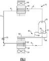
- the refrigerant vapor compression system 10 includes a compression device 20 driven by a motor 30 operatively associated therewith, a refrigerant heat rejecting heat exchanger 40, an evaporator expansion device 55, and a refrigerant heat absorbing heat exchanger 50, also referred to herein as an evaporator, connected in a closed loop refrigerant circuit in series refrigerant flow arrangement by various refrigerant lines 2, 4 and 6.
- the evaporator expansion device 55 is disposed in refrigerant line 4 downstream with respect to refrigerant flow of the refrigerant heat rejection heat exchanger 40 and upstream with respect to refrigerant flow of the evaporator 50.
- the refrigerant heat rejecting heat exchanger 40 is designed to operate as a refrigerant condensing heat exchanger through which hot, high pressure refrigerant vapor discharged from the compression device 20 passes in heat exchange relationship with a cooling medium to condense the refrigerant passing therethrough from a refrigerant vapor to refrigerant liquid.
- the refrigerant heat rejecting heat exchanger 40 is designed to operate as a refrigerant desuperheating heat exchanger through which hot, high pressure refrigerant vapor discharged from the compression device 20 passes in heat exchange relationship with a cooling medium to cool to a lower temperature, but not condense, the refrigerant vapor passing therethrough.
- the refrigerant condensing heat exchanger 40 may comprise a finned tube heat exchanger 42, such as for example, a fin and round tube heat exchange coil or a fin and flat mini-channel tube heat exchanger.
- the typical cooling medium is ambient air passed through the condenser 40 by means of fan(s) 44 operatively associated with the condenser 40 in heat exchange relationship with the refrigerant flowing through the heat exchanger 42.
- the evaporator 50 constitutes a refrigerant evaporating heat exchanger, such as a conventional finned tube heat exchanger 52, such as for example a fin and round tube heat exchange coil or a fin and mini-channel flat tube heat exchanger, through which expanded refrigerant having traversed the expansion device 55 passes in heat exchange relationship with a heating fluid, whereby the refrigerant is vaporized and typically superheated.
- the expansion device 55 which also meters refrigerant flow to the evaporator 50, may be an expansion valve, such as an electronic expansion valve or a thermostatic expansion valve, or a fixed orifice metering device, such a capillary tube.
- the heating fluid passed in heat exchange relationship with the refrigerant in the evaporator 50 may be air passed through the evaporator 50 by means of fan(s) 54 operatively associated with the evaporator 50, to be cooled and commonly also dehumidified, and thence supplied to a climate controlled environment such as a perishable cargo, such as for example refrigerated or frozen food items, storage zone associated with a transport refrigeration system, or a display case or cold room associated with a commercial refrigeration system, or an air conditioned space.
- a climate controlled environment such as a perishable cargo, such as for example refrigerated or frozen food items, storage zone associated with a transport refrigeration system, or a display case or cold room associated with a commercial refrigeration system, or an air conditioned space.
- the compression device 20 functions to compress and circulate refrigerant through the refrigerant circuit as will be discussed in further detail hereinafter.
- the compression device 20 may be a single-stage compression device, such as for example, but not limited to, a scroll compressor, a reciprocating compressor or rotary compressor, or a multi-stage compression device having at least a first low pressure compression stage and a second high pressure compression stage, such as for example, but not limited to, a scroll compressor, a reciprocating compressor or a screw compressor.
- the compression device 20 of the refrigerant vapor compression system 10 comprises a hermetic or semi-hermetic compressor driven by an oil-cooled motor.
- the compression device 20 of the refrigerant vapor compression system 10 comprises a hermetic or semi-hermetic compressor driven by a refrigerant-vapor cooled motor.
- the compressor drive motor 30 operatively associated with the compression mechanism of the compressor is disposed within the housing of the compressor 20, generally at an end of the drive shaft opposite the compression mechanism.
- the compressor drive motor 30 may be oil-cooled, in which case, the motor is disposed in an oil sump 32 within the interior of the compressor housing.
- the oil serves also to lubricate the interacting elements of the compression mechanism and seal gaps to reduce leakage between the interacting elements during the compression process.
- the compressor drive motor 30 may be refrigerant vapor-cooled, which is the case when the compressor drive motor is disposed in a higher region of the interior of the compressor housing.
- a lubricant is generally added to the refrigerant circulating through the refrigerant circuit of the refrigerant vapor compression system to lubricate the interacting elements of the compression mechanism and seal gaps to reduce leakage between the interacting elements during the compression process.
- the refrigerant vapor compression system 10 of the invention includes an oil-cooler circuit 60 comprising a oil cooler heat exchange tube coil 62 disposed in heat exchange relationship with the cooled air having been passed over the heat exchanger 52 of the evaporator 50 by means of the evaporator fan(s) 54.
- the oil cooler heat exchange coil 62 has an inlet leg 64 and an outlet leg 66.
- the length of the oil cooler heat exchanger coil 62 disposed in the cooled air stream leaving the evaporator 50 must be determined on a case-by-case basis based on the desired oil return temperature, the oil mass flow, oil properties and the amount of heat rejected by the compressor drive motor.
- the first leg 64 of the oil cooler heat exchange coil 62 is in fluid flow communication with the oil sump 32 of the compressor 20 to receive oil therefrom and an outlet leg 66 in fluid communication with the oil sump 32 for returning the cooled oil thereto.
- the oil is circulated from the oil sump 32 through the inlet leg 64, thence the oil cooler heat exchange coil 62 and thence returned via the outlet leg 66 to the oil sump 32 by means of an oil pump (not shown) disposed within the interior of the compressor housing and driven by the compressor drive motor 30.
- the refrigerant vapor compression system 10 depicted therein has a refrigerant vapor-cooled motor driving the compression device 20.
- the oil-cooler circuit 60 of the refrigerant vapor compression system 10 further includes an oil separator 70 disposed in refrigerant line 2 downstream with respect to refrigerant flow of the compressor 20 and upstream with respect to refrigerant flow of the refrigerant heat rejection heat exchanger 40.
- the refrigerant vapor discharging from the compressor 20 passes, with lubricating oil entrained therein, into the oil separator 70 wherein the oil separates from the refrigerant vapor and collects in the lower reservoir 72 of the oil separator.
- the inlet leg 64 of the oil-cooler heat exchange coil 62 is in fluid flow communication with the lower reservoir 72 of the oil separator 70 to receive oil therefrom and an outlet leg 66 in fluid communication with the compressor 20 for returning the cooled oil to the suction side of the compressor.
- the collected oil being at compressor discharge pressure, flows by pressure differential through the inlet leg 64, thence the oil cooler heat exchange coil 60 and thence returns via the outlet leg 66 to the suction side of the compressor 20.
- the oil flowing through the oil cooler heat exchanger coil 60 is cooled, typically by about 3° C to about 20° C (about 37.4°F to about 68°F), as it passes in heat exchange relationship with the cooled air passing from the evaporator 50 to return to the climate controlled environment.
- the cooled air passing from the evaporator 50 is slightly reheated, typically by less than about 1-3 °C (1.8 - 5.4°F).
- the oil-cooler circuit 60 may be readily employed in connection with various variations of the basic refrigerant vapor compression cycle.
- the refrigerant vapor compression system could be equipped with an economizer circuit, a compressor unload circuit, a flash tank receiver or other enhancement.
Landscapes
- Engineering & Computer Science (AREA)
- Physics & Mathematics (AREA)
- Mechanical Engineering (AREA)
- Thermal Sciences (AREA)
- General Engineering & Computer Science (AREA)
- Compressor (AREA)
- Applications Or Details Of Rotary Compressors (AREA)
- Lubricants (AREA)
- Devices That Are Associated With Refrigeration Equipment (AREA)
Claims (5)
- Kältemitteldampfkompressionssystem (10), umfassend:einen Kältemittelkreislauf, der eine Kältemittelkompressionsvorrichtung (20), einen Wärmetauscher zur Wärmeabgabe von Kältemittel (40) zum Leiten von Kältemittel, das von der Verdichtervorrichtung (20) mit einem hohen Druck empfangen wurde, in einer Wärmetauscherbeziehung mit einem Kühlmedium, einen Wärmetauscher zur Wärmeabsorption von Kältemittel (50) zum Leiten von Kältemittel mit einem niedrigen Druck, wobei das Kältemittel in einer Wärmetauscherbeziehung mit einem Heizmedium steht, beinhaltet; undeinen Schmiermittelkühlkreislauf (60), der funktionsfähig mit der Verdichtervorrichtung (20) verknüpft ist, zum Kühlen eines Schmiermittels, das mit der Verdichtervorrichtung (20) verknüpft ist, wobei der Schmiermittelkühlkreislauf (60) eine Wärmetauscherspirale (62) beinhaltet;wobei der Wärmetauscher zur Wärmeabsorption von Kältemittel (50) einen Kältemittelverdampfer-Wärmetauscher umfasst und das Heizmedium Luft aus einer klimatisierten Umgebung umfasst,dadurch gekennzeichnet, dass die Wärmetauscherspirale dem Wärmetauscher zur Wärmeabsorption von Kältemittel (50) in Bezug auf die Strömung des Heizmediums nachgeschaltet angeordnet ist und einen Strömungsweg zum Leiten des Schmiermittels in Wärmetauscherbeziehung mit dem gekühlten Heizmittel festlegt, das den Wärmetauscher zur Wärmeabsorption von Kältemittel (50) verlässt.
- Kältemitteldampfkompressionssystem (10) nach Anspruch 1, wobei die klimatisierte Umgebung eine Lagerzone für verderbliche Güter eines gekühlten Transportbehälters umfasst.
- Kältemitteldampfkompressionssystem (10) nach Anspruch 1, wobei die Schmiermittelkühlung-Wärmetauscherspirale (62) ferner einen Einlassstrang (64) zum Leiten von zu kühlendem Schmiermittel durch die Schmiermittelkühlung-Wärmetauscherspirale (62) zu dem Schmiermittel-Strömungsweg und einen Auslassstrang (66) zum Leiten von gekühltem Schmiermittel von dem Schmiermittel-Strömungsweg durch die Schmiermittelkühlung-Wärmetauscherspirale (62) umfasst.
- Kältemitteldampfkompressionssystem (10) nach Anspruch 3, wobei die Verdichtervorrichtung (20) einen hermetischen Verdichter mit einem Gehäuse, einen Verdichtermechanismus, einen ölgekühlten Motor zum Antreiben des Verdichtermechanismus und eine Ölwanne zum Sammeln von Öl zum Kühlen des Motors umfasst; wobei der Einlassstrang (64) der Schmiermittelkühlung-Wärmetauscherspirale (62) in strömungstechnischer Verbindung mit der Ölwanne des hermetischen Verdichters ist, um zu kühlendes Öl aufzunehmen, und der Auslassstrang (66) der Schmiermittelkühlung-Wärmetauscherspirale (62) in strömungstechnischer Verbindung mit der Ölwanne des hermetischen Verdichters ist, um gekühltes Öl zur Ölwanne zurückzuführen.
- Kältemitteldampfkompressionssystem (10) nach Anspruch 3, wobei die Verdichtervorrichtung (20) einen hermetischen Verdichter mit einem Gehäuse, einen Verdichtermechanismus und einen Motor zum Antreiben des Verdichtermechanismus umfasst; und
wobei der Schmiermittelkühlkreislauf (60) ferner einen Ölabscheider (70) beinhaltet, der in dem primären Kältemittelkreislauf in Bezug auf die Kältemittelströmung des Verdichters (20) vorgeschaltet und in Bezug auf die Kältemittelströmung des Wärmetauschers zur Wärmeabgabe von Kältemittel (40) nachgeschaltet angeordnet ist, wobei der Einlassstrang (64) der Schmiermittelkühlung-Wärmetauscherspirale (62) in strömungstechnischer Verbindung mit dem Ölabscheider (70) ist, um zu kühlendes Öl aufzunehmen, und der Auslassstrang (66) der Schmiermittelkühlung-Wärmetauscherspirale (62) in strömungstechnischer Verbindung mit dem hermetischen Verdichter ist, um gekühltes Öl zum hermetischen Verdichter zurückzuführen.
Applications Claiming Priority (1)
| Application Number | Priority Date | Filing Date | Title |
|---|---|---|---|
| PCT/US2008/051342 WO2009091403A1 (en) | 2008-01-17 | 2008-01-17 | Refrigerant vapor compression system with lubricant cooler |
Publications (3)
| Publication Number | Publication Date |
|---|---|
| EP2229563A1 EP2229563A1 (de) | 2010-09-22 |
| EP2229563A4 EP2229563A4 (de) | 2016-02-24 |
| EP2229563B1 true EP2229563B1 (de) | 2018-03-07 |
Family
ID=40885572
Family Applications (1)
| Application Number | Title | Priority Date | Filing Date |
|---|---|---|---|
| EP08713802.0A Not-in-force EP2229563B1 (de) | 2008-01-17 | 2008-01-17 | Kältemitteldampfkompressionssystem mit schmiermittelkühler |
Country Status (6)
| Country | Link |
|---|---|
| US (1) | US8424337B2 (de) |
| EP (1) | EP2229563B1 (de) |
| JP (1) | JP2011510258A (de) |
| CN (1) | CN101910756B (de) |
| DK (1) | DK2229563T3 (de) |
| WO (1) | WO2009091403A1 (de) |
Families Citing this family (37)
| Publication number | Priority date | Publication date | Assignee | Title |
|---|---|---|---|---|
| JP5103952B2 (ja) * | 2007-03-08 | 2012-12-19 | ダイキン工業株式会社 | 冷凍装置 |
| CN102170967B (zh) * | 2008-10-06 | 2014-03-26 | 昭和电工株式会社 | 催化剂及其制造方法以及其用途 |
| FR2942656B1 (fr) * | 2009-02-27 | 2013-04-12 | Danfoss Commercial Compressors | Dispositif de separation de lubrifiant d'un melange lubrifiant-gaz frigorigene |
| NO20093496A1 (no) * | 2009-12-09 | 2011-06-06 | E Innovation As | Anordning ved pusteluftaggregat |
| CA2850224A1 (en) * | 2011-10-03 | 2013-04-11 | Fallbrook Intellectual Property Company Llc | Refrigeration system having a continuously variable transmission |
| CN103913014B (zh) * | 2012-12-31 | 2016-05-25 | 珠海格力电器股份有限公司 | 回油装置及具有该回油装置的空调机组 |
| DE102013211084A1 (de) * | 2013-06-14 | 2014-12-18 | Siemens Aktiengesellschaft | Verfahren zum Betrieb einer Wärmepumpe und Wärmepumpe |
| US10408508B2 (en) | 2013-06-17 | 2019-09-10 | Carrier Corporation | Oil recovery for refrigeration system |
| EP3071904B1 (de) * | 2013-10-31 | 2019-05-15 | Emerson Climate Technologies, Inc. | Wärmepumpensystem |
| CN105683686B (zh) | 2013-11-04 | 2018-06-05 | 开利公司 | 具有油分离的制冷回路 |
| CN106796065A (zh) * | 2014-09-09 | 2017-05-31 | 开利公司 | 冷却器压缩机油调节 |
| JP6328269B2 (ja) * | 2014-11-26 | 2018-05-23 | 三菱電機株式会社 | 熱源側ユニットおよび冷凍サイクル装置 |
| DE102015121595B4 (de) | 2015-12-11 | 2020-04-09 | Hanon Systems | Vorrichtung zum Speichern von Öl eines Kältemittelkreislaufs |
| DE102015121588A1 (de) | 2015-12-11 | 2017-06-14 | Hanon Systems | Vorrichtung zur Rückführung von Öl in einem Kältemittelkreislauf und Verfahren zum Betreiben der Vorrichtung |
| DE102015121583B4 (de) * | 2015-12-11 | 2021-02-11 | Hanon Systems | Vorrichtung zum Abscheiden von Öl eines Kältemittel-Öl-Gemisches sowie zum Abkühlen des Öls und zum Abkühlen und/oder Verflüssigen des Kältemittels in einem Kältemittelkreislauf |
| DE102015121594A1 (de) * | 2015-12-11 | 2017-06-29 | Hanon Systems | Vorrichtung zum Abscheiden von Öl eines Kältemittel-Öl-Gemisches in einem Kältemittelkreislauf sowie Anordnung mit der Vorrichtung und einem Wärmeübertrager zum Abkühlen des Öls |
| US10543737B2 (en) | 2015-12-28 | 2020-01-28 | Thermo King Corporation | Cascade heat transfer system |
| US10240602B2 (en) * | 2016-07-15 | 2019-03-26 | Ingersoll-Rand Company | Compressor system and method for conditioning inlet air |
| US10724524B2 (en) | 2016-07-15 | 2020-07-28 | Ingersoll-Rand Industrial U.S., Inc | Compressor system and lubricant control valve to regulate temperature of a lubricant |
| DE102017111888B4 (de) | 2017-05-31 | 2023-06-15 | Hanon Systems | Kälteanlage mit separatem Ölkreislauf |
| BE1026208B1 (nl) * | 2018-04-12 | 2019-11-13 | Atlas Copco Airpower Naamloze Vennootschap | Oliegeïnjecteerde schroefcompressorinrichting |
| CN108954914A (zh) * | 2018-08-08 | 2018-12-07 | 广东欧亚制冷设备制造有限公司 | 一种低环境温度空气源热泵机组 |
| CN108954996A (zh) * | 2018-09-30 | 2018-12-07 | 珠海格力电器股份有限公司 | 油分离装置及设有其的热交换系统 |
| US11911724B2 (en) | 2018-12-03 | 2024-02-27 | Carrier Corporation | Enhanced refrigeration purge system |
| WO2020117580A1 (en) | 2018-12-03 | 2020-06-11 | Carrier Corporation | Membrane purge system |
| EP3891448A1 (de) | 2018-12-03 | 2021-10-13 | Carrier Corporation | Verbessertes kühlspülsystem |
| US11976860B2 (en) | 2018-12-03 | 2024-05-07 | Carrier Corporation | Enhanced refrigeration purge system |
| US11530856B2 (en) | 2018-12-17 | 2022-12-20 | Trane International Inc. | Systems and methods for controlling compressor motors |
| US11209199B2 (en) * | 2019-02-07 | 2021-12-28 | Heatcraft Refrigeration Products Llc | Cooling system |
| US11085681B2 (en) | 2019-02-07 | 2021-08-10 | Heatcraft Refrigeration Products Llc | Cooling system |
| ES2912000T3 (es) * | 2019-05-21 | 2022-05-24 | Carrier Corp | Aparato de refrigeración y uso del mismo |
| ES2980113T3 (es) * | 2019-05-21 | 2024-09-30 | Carrier Corp | Aparato de refrigeración |
| US11268746B2 (en) * | 2019-12-17 | 2022-03-08 | Heatcraft Refrigeration Products Llc | Cooling system with partly flooded low side heat exchanger |
| US11149997B2 (en) * | 2020-02-05 | 2021-10-19 | Heatcraft Refrigeration Products Llc | Cooling system with vertical alignment |
| DE102020117899B4 (de) * | 2020-07-07 | 2022-11-17 | SPH Sustainable Process Heat GmbH | Hochtemperaturwärmepumpe |
| CN112682986B (zh) * | 2021-01-11 | 2024-03-22 | 珠海格力电器股份有限公司 | 一种闪发式油冷系统及控制方法 |
| US11898571B2 (en) | 2021-12-30 | 2024-02-13 | Trane International Inc. | Compressor lubrication supply system and compressor thereof |
Family Cites Families (31)
| Publication number | Priority date | Publication date | Assignee | Title |
|---|---|---|---|---|
| US2677944A (en) * | 1950-12-01 | 1954-05-11 | Alonzo W Ruff | Plural stage refrigeration apparatus |
| US2963886A (en) * | 1958-01-02 | 1960-12-13 | Carrier Corp | Lubricant cooling system |
| JPS493528Y1 (de) * | 1968-08-21 | 1974-01-28 | ||
| US3759348A (en) * | 1971-11-08 | 1973-09-18 | Maekawa Seisakusho Kk | Method of compressing chlorine gas |
| JPS5529011Y2 (de) * | 1975-03-18 | 1980-07-10 | ||
| JPS56121888A (en) * | 1980-02-29 | 1981-09-24 | Tokico Ltd | Oil-cooled compressor |
| US4516916A (en) * | 1982-12-09 | 1985-05-14 | Westinghouse Electric Corp. | Oil cooled, hermetic refrigerant compressor |
| JPS63129159U (de) * | 1987-02-13 | 1988-08-24 | ||
| JPH01314873A (ja) | 1988-06-15 | 1989-12-20 | Toshiba Corp | 冷凍車用冷凍装置 |
| US4949546A (en) * | 1988-11-14 | 1990-08-21 | Helix Technology Corporation | Compact heat exchanger for a cryogenic refrigerator |
| US5033944A (en) * | 1989-09-07 | 1991-07-23 | Unotech Corporation | Lubricant circuit for a compressor unit and process of circulating lubricant |
| US5222874A (en) * | 1991-01-09 | 1993-06-29 | Sullair Corporation | Lubricant cooled electric drive motor for a compressor |
| US5245833A (en) * | 1992-05-19 | 1993-09-21 | Martin Marietta Energy Systems, Inc. | Liquid over-feeding air conditioning system and method |
| AU5952994A (en) * | 1993-03-31 | 1994-10-24 | American Standard, Inc. | Cooling of compressor lubricant in a refrigeration system |
| JP2677762B2 (ja) * | 1994-04-08 | 1997-11-17 | 株式会社神戸製鋼所 | 油冷式圧縮機 |
| US5899091A (en) * | 1997-12-15 | 1999-05-04 | Carrier Corporation | Refrigeration system with integrated economizer/oil cooler |
| US6058727A (en) * | 1997-12-19 | 2000-05-09 | Carrier Corporation | Refrigeration system with integrated oil cooling heat exchanger |
| CN1123745C (zh) * | 1999-05-08 | 2003-10-08 | 三菱电机株式会社 | 空调系统及其装配方法 |
| US6170286B1 (en) * | 1999-07-09 | 2001-01-09 | American Standard Inc. | Oil return from refrigeration system evaporator using hot oil as motive force |
| US6182467B1 (en) * | 1999-09-27 | 2001-02-06 | Carrier Corporation | Lubrication system for screw compressors using an oil still |
| US6233967B1 (en) * | 1999-12-03 | 2001-05-22 | American Standard International Inc. | Refrigeration chiller oil recovery employing high pressure oil as eductor motive fluid |
| US6579335B2 (en) * | 2000-10-23 | 2003-06-17 | Walter Duane Ollinger | Oil separator and cooler |
| US6457325B1 (en) * | 2000-10-31 | 2002-10-01 | Modine Manufacturing Company | Refrigeration system with phase separation |
| US6481243B1 (en) * | 2001-04-02 | 2002-11-19 | Wei Fang | Pressure accumulator at high pressure side and waste heat re-use device for vapor compressed air conditioning or refrigeration equipment |
| US6880360B2 (en) * | 2002-10-03 | 2005-04-19 | York International Corporation | Compressor systems for use with smokeless lubricant |
| JP2004177020A (ja) * | 2002-11-28 | 2004-06-24 | Denso Corp | 給湯器 |
| US20040112679A1 (en) * | 2002-12-13 | 2004-06-17 | Centers Steven D. | System and method for lubricant flow control in a variable speed compressor package |
| CN2682345Y (zh) * | 2003-11-19 | 2005-03-02 | 上海三电贝洱汽车空调有限公司 | 汽车空调制冷系统防止润滑油误流的装置 |
| WO2006095572A1 (ja) | 2005-03-09 | 2006-09-14 | Matsushita Electric Industrial Co., Ltd. | 冷凍サイクル装置 |
| JP2007107771A (ja) | 2005-10-12 | 2007-04-26 | Matsushita Electric Ind Co Ltd | 冷凍サイクル装置 |
| US20070214827A1 (en) * | 2006-03-20 | 2007-09-20 | Chadalavada Venkatasubramaniam | Oil-free refrigerant circulation technology for air-conditioning and refrigeration system |
-
2008
- 2008-01-17 EP EP08713802.0A patent/EP2229563B1/de not_active Not-in-force
- 2008-01-17 US US12/745,772 patent/US8424337B2/en not_active Expired - Fee Related
- 2008-01-17 WO PCT/US2008/051342 patent/WO2009091403A1/en not_active Ceased
- 2008-01-17 CN CN200880125331.0A patent/CN101910756B/zh not_active Expired - Fee Related
- 2008-01-17 DK DK08713802.0T patent/DK2229563T3/en active
- 2008-01-17 JP JP2010543101A patent/JP2011510258A/ja active Pending
Non-Patent Citations (1)
| Title |
|---|
| None * |
Also Published As
| Publication number | Publication date |
|---|---|
| EP2229563A4 (de) | 2016-02-24 |
| DK2229563T3 (en) | 2018-04-30 |
| WO2009091403A1 (en) | 2009-07-23 |
| EP2229563A1 (de) | 2010-09-22 |
| US8424337B2 (en) | 2013-04-23 |
| HK1151577A1 (en) | 2012-02-03 |
| JP2011510258A (ja) | 2011-03-31 |
| CN101910756B (zh) | 2015-06-24 |
| US20100251756A1 (en) | 2010-10-07 |
| CN101910756A (zh) | 2010-12-08 |
Similar Documents
| Publication | Publication Date | Title |
|---|---|---|
| EP2229563B1 (de) | Kältemitteldampfkompressionssystem mit schmiermittelkühler | |
| US8671703B2 (en) | Refrigerant vapor compression system with flash tank economizer | |
| EP2147264B1 (de) | Kältemitteldampfkompressionssystem | |
| EP2564130B1 (de) | Kältedampfkompressionssystem mit zwischenkühler | |
| DK2526351T3 (en) | COOL STORAGE IN A COOLANT Vapor Compression System | |
| EP2245387B1 (de) | Kapazitätsmodulierung einer kältemitteldampfkompressionsanlage | |
| US8528359B2 (en) | Economized refrigeration cycle with expander | |
| US20110041523A1 (en) | Charge management in refrigerant vapor compression systems | |
| US11885533B2 (en) | Refrigerant vapor compression system | |
| HK1151577B (en) | Refrigerant vapor compression system with lubricant cooler | |
| HK1160206A (zh) | 製冷劑蒸汽壓縮系統中的充注量管理 | |
| HK1125167A1 (en) | Vapor compression system with condensate intercooling between compression stages | |
| HK1142389B (en) | Refrigerant vapor compression system with flash tank economizer | |
| HK1161635A (en) | Capacity boosting during pulldown | |
| HK1177491A (en) | Refrigeration storage in a refrigerant vapor compression system | |
| HK1142666B (en) | Refrigerant vapor compression system with dual economizer circuits | |
| HK1142666A1 (en) | Refrigerant vapor compression system with dual economizer circuits |
Legal Events
| Date | Code | Title | Description |
|---|---|---|---|
| PUAI | Public reference made under article 153(3) epc to a published international application that has entered the european phase |
Free format text: ORIGINAL CODE: 0009012 |
|
| 17P | Request for examination filed |
Effective date: 20100514 |
|
| AK | Designated contracting states |
Kind code of ref document: A1 Designated state(s): AT BE BG CH CY CZ DE DK EE ES FI FR GB GR HR HU IE IS IT LI LT LU LV MC MT NL NO PL PT RO SE SI SK TR |
|
| AX | Request for extension of the european patent |
Extension state: AL BA MK RS |
|
| DAX | Request for extension of the european patent (deleted) | ||
| RA4 | Supplementary search report drawn up and despatched (corrected) |
Effective date: 20160127 |
|
| RIC1 | Information provided on ipc code assigned before grant |
Ipc: F25B 31/02 20060101AFI20160121BHEP |
|
| STAA | Information on the status of an ep patent application or granted ep patent |
Free format text: STATUS: REQUEST FOR EXAMINATION WAS MADE |
|
| R17P | Request for examination filed (corrected) |
Effective date: 20100514 |
|
| GRAP | Despatch of communication of intention to grant a patent |
Free format text: ORIGINAL CODE: EPIDOSNIGR1 |
|
| STAA | Information on the status of an ep patent application or granted ep patent |
Free format text: STATUS: GRANT OF PATENT IS INTENDED |
|
| INTG | Intention to grant announced |
Effective date: 20170918 |
|
| GRAS | Grant fee paid |
Free format text: ORIGINAL CODE: EPIDOSNIGR3 |
|
| GRAA | (expected) grant |
Free format text: ORIGINAL CODE: 0009210 |
|
| STAA | Information on the status of an ep patent application or granted ep patent |
Free format text: STATUS: THE PATENT HAS BEEN GRANTED |
|
| AK | Designated contracting states |
Kind code of ref document: B1 Designated state(s): AT BE BG CH CY CZ DE DK EE ES FI FR GB GR HR HU IE IS IT LI LT LU LV MC MT NL NO PL PT RO SE SI SK TR |
|
| REG | Reference to a national code |
Ref country code: GB Ref legal event code: FG4D |
|
| REG | Reference to a national code |
Ref country code: CH Ref legal event code: EP Ref country code: AT Ref legal event code: REF Ref document number: 977005 Country of ref document: AT Kind code of ref document: T Effective date: 20180315 |
|
| REG | Reference to a national code |
Ref country code: IE Ref legal event code: FG4D |
|
| REG | Reference to a national code |
Ref country code: DE Ref legal event code: R096 Ref document number: 602008054322 Country of ref document: DE |
|
| REG | Reference to a national code |
Ref country code: DK Ref legal event code: T3 Effective date: 20180423 |
|
| REG | Reference to a national code |
Ref country code: NL Ref legal event code: MP Effective date: 20180307 |
|
| REG | Reference to a national code |
Ref country code: LT Ref legal event code: MG4D |
|
| PG25 | Lapsed in a contracting state [announced via postgrant information from national office to epo] |
Ref country code: NO Free format text: LAPSE BECAUSE OF FAILURE TO SUBMIT A TRANSLATION OF THE DESCRIPTION OR TO PAY THE FEE WITHIN THE PRESCRIBED TIME-LIMIT Effective date: 20180607 Ref country code: ES Free format text: LAPSE BECAUSE OF FAILURE TO SUBMIT A TRANSLATION OF THE DESCRIPTION OR TO PAY THE FEE WITHIN THE PRESCRIBED TIME-LIMIT Effective date: 20180307 Ref country code: HR Free format text: LAPSE BECAUSE OF FAILURE TO SUBMIT A TRANSLATION OF THE DESCRIPTION OR TO PAY THE FEE WITHIN THE PRESCRIBED TIME-LIMIT Effective date: 20180307 Ref country code: CY Free format text: LAPSE BECAUSE OF FAILURE TO SUBMIT A TRANSLATION OF THE DESCRIPTION OR TO PAY THE FEE WITHIN THE PRESCRIBED TIME-LIMIT Effective date: 20180307 Ref country code: LT Free format text: LAPSE BECAUSE OF FAILURE TO SUBMIT A TRANSLATION OF THE DESCRIPTION OR TO PAY THE FEE WITHIN THE PRESCRIBED TIME-LIMIT Effective date: 20180307 Ref country code: FI Free format text: LAPSE BECAUSE OF FAILURE TO SUBMIT A TRANSLATION OF THE DESCRIPTION OR TO PAY THE FEE WITHIN THE PRESCRIBED TIME-LIMIT Effective date: 20180307 |
|
| REG | Reference to a national code |
Ref country code: AT Ref legal event code: MK05 Ref document number: 977005 Country of ref document: AT Kind code of ref document: T Effective date: 20180307 |
|
| PG25 | Lapsed in a contracting state [announced via postgrant information from national office to epo] |
Ref country code: GR Free format text: LAPSE BECAUSE OF FAILURE TO SUBMIT A TRANSLATION OF THE DESCRIPTION OR TO PAY THE FEE WITHIN THE PRESCRIBED TIME-LIMIT Effective date: 20180608 Ref country code: LV Free format text: LAPSE BECAUSE OF FAILURE TO SUBMIT A TRANSLATION OF THE DESCRIPTION OR TO PAY THE FEE WITHIN THE PRESCRIBED TIME-LIMIT Effective date: 20180307 Ref country code: SE Free format text: LAPSE BECAUSE OF FAILURE TO SUBMIT A TRANSLATION OF THE DESCRIPTION OR TO PAY THE FEE WITHIN THE PRESCRIBED TIME-LIMIT Effective date: 20180307 Ref country code: BG Free format text: LAPSE BECAUSE OF FAILURE TO SUBMIT A TRANSLATION OF THE DESCRIPTION OR TO PAY THE FEE WITHIN THE PRESCRIBED TIME-LIMIT Effective date: 20180607 |
|
| PG25 | Lapsed in a contracting state [announced via postgrant information from national office to epo] |
Ref country code: EE Free format text: LAPSE BECAUSE OF FAILURE TO SUBMIT A TRANSLATION OF THE DESCRIPTION OR TO PAY THE FEE WITHIN THE PRESCRIBED TIME-LIMIT Effective date: 20180307 Ref country code: PL Free format text: LAPSE BECAUSE OF FAILURE TO SUBMIT A TRANSLATION OF THE DESCRIPTION OR TO PAY THE FEE WITHIN THE PRESCRIBED TIME-LIMIT Effective date: 20180307 Ref country code: NL Free format text: LAPSE BECAUSE OF FAILURE TO SUBMIT A TRANSLATION OF THE DESCRIPTION OR TO PAY THE FEE WITHIN THE PRESCRIBED TIME-LIMIT Effective date: 20180307 Ref country code: RO Free format text: LAPSE BECAUSE OF FAILURE TO SUBMIT A TRANSLATION OF THE DESCRIPTION OR TO PAY THE FEE WITHIN THE PRESCRIBED TIME-LIMIT Effective date: 20180307 |
|
| PG25 | Lapsed in a contracting state [announced via postgrant information from national office to epo] |
Ref country code: AT Free format text: LAPSE BECAUSE OF FAILURE TO SUBMIT A TRANSLATION OF THE DESCRIPTION OR TO PAY THE FEE WITHIN THE PRESCRIBED TIME-LIMIT Effective date: 20180307 Ref country code: CZ Free format text: LAPSE BECAUSE OF FAILURE TO SUBMIT A TRANSLATION OF THE DESCRIPTION OR TO PAY THE FEE WITHIN THE PRESCRIBED TIME-LIMIT Effective date: 20180307 Ref country code: SK Free format text: LAPSE BECAUSE OF FAILURE TO SUBMIT A TRANSLATION OF THE DESCRIPTION OR TO PAY THE FEE WITHIN THE PRESCRIBED TIME-LIMIT Effective date: 20180307 |
|
| REG | Reference to a national code |
Ref country code: DE Ref legal event code: R097 Ref document number: 602008054322 Country of ref document: DE |
|
| PG25 | Lapsed in a contracting state [announced via postgrant information from national office to epo] |
Ref country code: PT Free format text: LAPSE BECAUSE OF FAILURE TO SUBMIT A TRANSLATION OF THE DESCRIPTION OR TO PAY THE FEE WITHIN THE PRESCRIBED TIME-LIMIT Effective date: 20180709 |
|
| PLBE | No opposition filed within time limit |
Free format text: ORIGINAL CODE: 0009261 |
|
| STAA | Information on the status of an ep patent application or granted ep patent |
Free format text: STATUS: NO OPPOSITION FILED WITHIN TIME LIMIT |
|
| 26N | No opposition filed |
Effective date: 20181210 |
|
| PG25 | Lapsed in a contracting state [announced via postgrant information from national office to epo] |
Ref country code: IT Free format text: LAPSE BECAUSE OF FAILURE TO SUBMIT A TRANSLATION OF THE DESCRIPTION OR TO PAY THE FEE WITHIN THE PRESCRIBED TIME-LIMIT Effective date: 20180307 Ref country code: SI Free format text: LAPSE BECAUSE OF FAILURE TO SUBMIT A TRANSLATION OF THE DESCRIPTION OR TO PAY THE FEE WITHIN THE PRESCRIBED TIME-LIMIT Effective date: 20180307 |
|
| REG | Reference to a national code |
Ref country code: DE Ref legal event code: R119 Ref document number: 602008054322 Country of ref document: DE |
|
| REG | Reference to a national code |
Ref country code: DK Ref legal event code: EBP Effective date: 20190131 |
|
| PG25 | Lapsed in a contracting state [announced via postgrant information from national office to epo] |
Ref country code: MC Free format text: LAPSE BECAUSE OF FAILURE TO SUBMIT A TRANSLATION OF THE DESCRIPTION OR TO PAY THE FEE WITHIN THE PRESCRIBED TIME-LIMIT Effective date: 20180307 |
|
| REG | Reference to a national code |
Ref country code: CH Ref legal event code: PL |
|
| GBPC | Gb: european patent ceased through non-payment of renewal fee |
Effective date: 20190117 |
|
| PG25 | Lapsed in a contracting state [announced via postgrant information from national office to epo] |
Ref country code: LU Free format text: LAPSE BECAUSE OF NON-PAYMENT OF DUE FEES Effective date: 20190117 |
|
| REG | Reference to a national code |
Ref country code: BE Ref legal event code: MM Effective date: 20190131 |
|
| REG | Reference to a national code |
Ref country code: IE Ref legal event code: MM4A |
|
| PG25 | Lapsed in a contracting state [announced via postgrant information from national office to epo] |
Ref country code: FR Free format text: LAPSE BECAUSE OF NON-PAYMENT OF DUE FEES Effective date: 20190131 Ref country code: DE Free format text: LAPSE BECAUSE OF NON-PAYMENT OF DUE FEES Effective date: 20190801 |
|
| PG25 | Lapsed in a contracting state [announced via postgrant information from national office to epo] |
Ref country code: BE Free format text: LAPSE BECAUSE OF NON-PAYMENT OF DUE FEES Effective date: 20190131 |
|
| PG25 | Lapsed in a contracting state [announced via postgrant information from national office to epo] |
Ref country code: LI Free format text: LAPSE BECAUSE OF NON-PAYMENT OF DUE FEES Effective date: 20190131 Ref country code: GB Free format text: LAPSE BECAUSE OF NON-PAYMENT OF DUE FEES Effective date: 20190117 Ref country code: CH Free format text: LAPSE BECAUSE OF NON-PAYMENT OF DUE FEES Effective date: 20190131 |
|
| PG25 | Lapsed in a contracting state [announced via postgrant information from national office to epo] |
Ref country code: DK Free format text: LAPSE BECAUSE OF NON-PAYMENT OF DUE FEES Effective date: 20190131 Ref country code: IE Free format text: LAPSE BECAUSE OF NON-PAYMENT OF DUE FEES Effective date: 20190117 |
|
| PG25 | Lapsed in a contracting state [announced via postgrant information from national office to epo] |
Ref country code: TR Free format text: LAPSE BECAUSE OF FAILURE TO SUBMIT A TRANSLATION OF THE DESCRIPTION OR TO PAY THE FEE WITHIN THE PRESCRIBED TIME-LIMIT Effective date: 20180307 |
|
| PG25 | Lapsed in a contracting state [announced via postgrant information from national office to epo] |
Ref country code: MT Free format text: LAPSE BECAUSE OF NON-PAYMENT OF DUE FEES Effective date: 20190117 |
|
| PG25 | Lapsed in a contracting state [announced via postgrant information from national office to epo] |
Ref country code: IS Free format text: LAPSE BECAUSE OF FAILURE TO SUBMIT A TRANSLATION OF THE DESCRIPTION OR TO PAY THE FEE WITHIN THE PRESCRIBED TIME-LIMIT Effective date: 20180707 |
|
| PG25 | Lapsed in a contracting state [announced via postgrant information from national office to epo] |
Ref country code: HU Free format text: LAPSE BECAUSE OF FAILURE TO SUBMIT A TRANSLATION OF THE DESCRIPTION OR TO PAY THE FEE WITHIN THE PRESCRIBED TIME-LIMIT; INVALID AB INITIO Effective date: 20080117 |