EP2229207B1 - Verbesserungen im zusammenhang mit anti-asphyxationsventilen - Google Patents
Verbesserungen im zusammenhang mit anti-asphyxationsventilen Download PDFInfo
- Publication number
- EP2229207B1 EP2229207B1 EP08850371.9A EP08850371A EP2229207B1 EP 2229207 B1 EP2229207 B1 EP 2229207B1 EP 08850371 A EP08850371 A EP 08850371A EP 2229207 B1 EP2229207 B1 EP 2229207B1
- Authority
- EP
- European Patent Office
- Prior art keywords
- valve member
- interface device
- valve
- invasive ventilation
- asphyxiation
- Prior art date
- Legal status (The legal status is an assumption and is not a legal conclusion. Google has not performed a legal analysis and makes no representation as to the accuracy of the status listed.)
- Active
Links
Images


Classifications
-
- A—HUMAN NECESSITIES
- A61—MEDICAL OR VETERINARY SCIENCE; HYGIENE
- A61M—DEVICES FOR INTRODUCING MEDIA INTO, OR ONTO, THE BODY; DEVICES FOR TRANSDUCING BODY MEDIA OR FOR TAKING MEDIA FROM THE BODY; DEVICES FOR PRODUCING OR ENDING SLEEP OR STUPOR
- A61M16/00—Devices for influencing the respiratory system of patients by gas treatment, e.g. ventilators; Tracheal tubes
- A61M16/06—Respiratory or anaesthetic masks
-
- A—HUMAN NECESSITIES
- A61—MEDICAL OR VETERINARY SCIENCE; HYGIENE
- A61M—DEVICES FOR INTRODUCING MEDIA INTO, OR ONTO, THE BODY; DEVICES FOR TRANSDUCING BODY MEDIA OR FOR TAKING MEDIA FROM THE BODY; DEVICES FOR PRODUCING OR ENDING SLEEP OR STUPOR
- A61M16/00—Devices for influencing the respiratory system of patients by gas treatment, e.g. ventilators; Tracheal tubes
- A61M16/20—Valves specially adapted to medical respiratory devices
- A61M16/208—Non-controlled one-way valves, e.g. exhalation, check, pop-off non-rebreathing valves
-
- A—HUMAN NECESSITIES
- A61—MEDICAL OR VETERINARY SCIENCE; HYGIENE
- A61M—DEVICES FOR INTRODUCING MEDIA INTO, OR ONTO, THE BODY; DEVICES FOR TRANSDUCING BODY MEDIA OR FOR TAKING MEDIA FROM THE BODY; DEVICES FOR PRODUCING OR ENDING SLEEP OR STUPOR
- A61M16/00—Devices for influencing the respiratory system of patients by gas treatment, e.g. ventilators; Tracheal tubes
- A61M16/06—Respiratory or anaesthetic masks
- A61M16/0683—Holding devices therefor
-
- A—HUMAN NECESSITIES
- A61—MEDICAL OR VETERINARY SCIENCE; HYGIENE
- A61M—DEVICES FOR INTRODUCING MEDIA INTO, OR ONTO, THE BODY; DEVICES FOR TRANSDUCING BODY MEDIA OR FOR TAKING MEDIA FROM THE BODY; DEVICES FOR PRODUCING OR ENDING SLEEP OR STUPOR
- A61M16/00—Devices for influencing the respiratory system of patients by gas treatment, e.g. ventilators; Tracheal tubes
- A61M16/10—Preparation of respiratory gases or vapours
- A61M16/12—Preparation of respiratory gases or vapours by mixing different gases
-
- A—HUMAN NECESSITIES
- A61—MEDICAL OR VETERINARY SCIENCE; HYGIENE
- A61M—DEVICES FOR INTRODUCING MEDIA INTO, OR ONTO, THE BODY; DEVICES FOR TRANSDUCING BODY MEDIA OR FOR TAKING MEDIA FROM THE BODY; DEVICES FOR PRODUCING OR ENDING SLEEP OR STUPOR
- A61M2202/00—Special media to be introduced, removed or treated
- A61M2202/02—Gases
- A61M2202/0208—Oxygen
-
- A—HUMAN NECESSITIES
- A61—MEDICAL OR VETERINARY SCIENCE; HYGIENE
- A61M—DEVICES FOR INTRODUCING MEDIA INTO, OR ONTO, THE BODY; DEVICES FOR TRANSDUCING BODY MEDIA OR FOR TAKING MEDIA FROM THE BODY; DEVICES FOR PRODUCING OR ENDING SLEEP OR STUPOR
- A61M2205/00—General characteristics of the apparatus
- A61M2205/58—Means for facilitating use, e.g. by people with impaired vision
- A61M2205/583—Means for facilitating use, e.g. by people with impaired vision by visual feedback
Definitions
- This invention relates to anti-asphyxiation valves and in particular to anti-asphyxiation valves for use in non-invasive ventilation.
- Non-invasive ventilation is a process by which a flow of respiratory gas is delivered to the airway of a user through a non-invasive interface device, which is generally a respiratory mask, and hence without using an endotracheal or tracheostomy tube.
- Non-invasive ventilation is typically used to manage both chronic and acute respiratory failure, and also other medical disorders, such as sleep apnea.
- a respiratory mask during use is undesirable because it reduces alveolar ventilation and synchrony between the user and the ventilator, and hence respiratory masks for use in non-invasive ventilation are generally adapted to form an effective seal against the user's face.
- an anti-asphyxiation valve is typically provided in the breathing circuit to enable the user to inhale and exhale air to and from the atmosphere, in the event that the ventilator fails.
- Conventional anti-asphyxiation valves can be costly to manufacture, however, and hence relatively expensive to replace.
- the precise arrangement of the valve is typically critical in order for the valve to remain closed during normal use, but remain open during failure of the ventilator.
- conventional anti-asphyxiation valves are often separate components that need to be incorporated into the breathing circuit, and may be relatively bulky components.
- D1 ( GB2397244 ) discloses a respiratory mask having an anti-asphyxiation valve.
- the valve comprises a resilient diaphragm having a central aperture for the passage of air.
- D2 ( US4989596 ) discloses an anti-asphyxiation valve with a deformable valve member incorporated into the wall of a breathing mask device.
- D3 discloses an exhalation valve comprising a curved valve member.
- a non-invasive ventilation interface device comprising an anti-asphyxiation valve including one or more apertures for enabling passage of gas between the breathing circuit and the atmosphere, and a valve member deformable between an open configuration in which the one or more apertures are at least partially exposed and the passage of gas therethrough is enabled, and a closed configuration in which the valve member occludes the one or more apertures and the passage of gas therethrough is substantially prevented, the one or more apertures of the anti-asphyxiation valve being formed in a wall of the interface device, and the valve member having a continuous wall having a substantially conical or pyramidal configuration, wherein the valve member is adapted such that the pressure differential between the breathing circuit and atmospheric pressure at which the valve member deforms from the open configuration to the closed configuration is greater than the pressure differential between the breathing circuit and atmospheric pressure at which the valve member deforms from the closed configuration to the open configuration, wherein the valve member is mounted at the tip of the conical or pyramidal wall to an interior surface
- pressure within the breathing circuit is meant the pressure of the gas within the part of the breathing circuit into which the anti-asphyxiation valve is incorporated. Hence, this "pressure within the breathing circuit” is the pressure within the interface device.
- the non-invasive ventilation interface device is advantageous principally because the valve may be readily adapted such that (i) during normal operation of a ventilator the valve member reliably remains in its closed configuration, (ii) on failure of the ventilator the valve member is deformed into its open configuration, and (iii) the valve member reliably remains in its open configuration during unaided breathing of the user from the atmosphere.
- the anti-asphyxiation valve according to the invention is preferably an integral part of the interface device.
- the interface device according to this aspect of the invention is advantageous principally because although an anti-asphyxiation valve is incorporated into the interface device, the interface device may have a simple construction that is inexpensive to manufacture. Furthermore, the anti-asphyxiation valve may be entirely separate from one or more ports of the interface device through which gases flow into, and out of, the interface device from the remainder of the breathing circuit, and hence the effect on the valve of normal variations in airflow within the breathing circuit may be reduced.
- the valve member is preferably resiliently biased into its open configuration.
- deformation of the valve member away from the open configuration preferably causes internal stresses within the valve member that act to reform the valve member back to its open configuration. These internal stresses are typically compression or tensile stress.
- the valve member is formed of an elastomeric material, such as silicone, which is manufactured in its open configuration, for example by injection or compression moulding.
- the force resiliently biasing the valve member into its open configuration preferably increases as the deformation away from the open configuration increases.
- the valve member is preferably resiliently biased into its open configuration by a force that peaks in a configuration of the valve member that is intermediate of the open and closed configurations, such that the biasing force in the closed configuration is less than the peak biasing force between the open and closed configurations.
- the peak biasing force of the valve member, into the open configuration determines the pressure within the breathing circuit at which the valve member deforms from the open configuration to the closed configuration.
- This closing pressure is preferably substantially equal to, or greater than, the Positive End Expiratory Pressure (PEEP) applied to the breathing circuit.
- PEEP Positive End Expiratory Pressure
- the valve member is preferably adapted such that the anti-asphyxiation valve remains open during unaided breathing of the user, when the ventilator is not functioning.
- the pressure within the breathing circuit at which the valve member deforms from the closed configuration to the open configuration will be greater than atmospheric pressure.
- this opening pressure is less than the Positive End Expiratory Pressure (PEEP) applied to the breathing circuit, so that the anti-asphyxiation valve remains closed during normal operation of the breathing circuit and ventilator.
- PEEP Positive End Expiratory Pressure
- valve member may be resiliently biased into its open configuration until the valve member attains its closed configuration, wherein the stresses within the valve member are substantially at equilibrium, such that the pressure within the breathing circuit at which the valve member deforms from the closed configuration to the open configuration will be substantially equal to atmospheric pressure.
- valve member may be resiliently biased into its open configuration during deformation until the valve member reaches a transitional configuration, beyond which the valve member becomes resiliently biased into its closed configuration.
- the pressure within the breathing circuit at which the valve member deforms from the closed configuration to the open configuration will be less than atmospheric pressure.
- the anti-asphyxiation valve will therefore remain closed until the pressure within the breathing circuit is reduced below atmospheric pressure by inhalation of the user.
- this resilient biasing of the valve member into its closed configuration will improve the seal between the valve member and the associated valve seat in the closed configuration.
- the valve member is preferably adapted such that deformation of the valve member between the open and closed configurations causes at least part of the valve member to become stressed under either compression or tension, and this stress causes the resilient biasing of the valve member discussed above.
- the valve member In order that the valve member is resiliently biased into its open configuration by a force that peaks between the open and closed configurations, as discussed above, the valve member preferably has a configuration including an arcuate or folded member that is straightened on deformation away from its open configuration, and may be at least partially inverted in its closed configuration.
- valve member comprises a continuous wall having a substantially conical or pyramidal configuration
- valve member is preferably mounted at the tip of the conical or pyramidal wall to an interior surface of the interface device
- the interface device may have a simple construction that is inexpensive to manufacture.
- the valve member preferably comprises an opening at the tip of the conical or pyramidal wall, and an open base.
- the valve member may have any one of a variety of polygonal cross-sectional shapes, eg square, hexagonal, octagonal.
- the valve member preferably has a substantially conical configuration, and preferably has a substantially circular cross-sectional shape.
- the anti-asphyxiation valve preferably includes a valve seat that surrounds the one or more apertures, and preferably also surrounds each individual aperture.
- the valve seat is preferably defined by part of the interior surface of the interface device, which is preferably raised relative to the surrounding interior surface.
- the valve member is preferably mounted to an interior surface of the interface device, such that deformation of the valve member into its closed configuration causes the valve member to engage the valve seat.
- the form of the valve seat preferably therefore determines the closed configuration of the valve member.
- the valve member is preferably adapted to be flattened on deformation away from its open configuration, and may have either (i) a closed configuration in which the inclination of the wall of the valve member is reduced relative to the open configuration, (ii) a closed configuration in which the wall of the valve member is substantially flat, or (iii) a closed configuration in which the valve member is at least partially inverted relative to the open configuration.
- the form of the valve seat, and hence the closed configuration of the valve member preferably at least partially determines the pressure within the interface device at which the valve member deforms from the closed configuration to the open configuration. For instance, where the valve member has a closed configuration in which the inclination of the wall of the valve member is reduced relative to the open configuration, the pressure within the interface device at which the valve member deforms from the closed configuration to the open configuration will be greater than atmospheric pressure, as discussed in more detail above. Where the valve member has a closed configuration in which the wall of the valve member is substantially flat, the pressure within the interface device at which the valve member deforms from the closed configuration to the open configuration will be substantially equal to atmospheric pressure. Where the valve member has a closed configuration in which the valve member is at least partially inverted relative to the open configuration, the pressure within the interface device at which the valve member deforms from the closed configuration to the open configuration will be less than atmospheric pressure, as discussed in more detail above.
- the substantially conical or pyramidal valve member is preferably mounted relative to the one or more apertures by a retainer that extends through an opening at the tip of the valve member.
- the valve member is preferably not bonded to the retainer, such that deformation of the valve member will not cause stresses at the interface between the valve member and the retainer.
- the retainer preferably includes an enlarged head having a greater width than the width of the valve member opening, such that the valve member engages the retainer with a snap fit.
- valve member is able to be inverted, such as in the case of a conical or pyramidal valve member
- valve member preferably includes an indication regarding the correct configuration for assembly of the valve.
- an indication may take the form of a formation, such as a rib, on one of the surfaces of the valve member.
- the interface device preferably includes a port for connection of the interface device to the breathing circuit.
- the connection port is preferably therefore adapted to enable inhalation gases to be supplied to the interface device, and exhalation gases to be removed from the interface device, during normal use.
- the anti-asphyxiation valve and the connection port are preferably entirely separate parts of the interface device, and are preferably formed in distinct parts of the wall of the interface device.
- the interface device preferably also includes a flow deflector interposed between the connection port and the anti-asphyxiation valve. The flow deflector is preferably adapted to shield the anti-asphyxiation valve from the connection port, thereby reducing the proportion of gas that flows directly between the connection port and the anti-asphyxiation valve when the valve member is in its open configuration.
- the interface device preferably also includes one or more vent openings in the wall of the interface device, which have an area that is substantially less than the area of the one or more apertures of the anti-asphyxiation valve. These vent openings preferably facilitate removal of exhalation gases, and in particular carbon dioxide, from the interface device during normal use.
- the interface device may also include an additional port, which enables a supplementary supply of oxygen to be connected to the interface device and supplied to the user, for example.
- the interface device is typically a respiratory mask, which preferably comprises a mask body, and one or more sealing components extending from the peripheral edge of the mask body and defining a contact surface that contacts the face of the user during use.
- the respiratory mask preferably defines a cavity that accommodates the user's nose and mouth when fitted to the user.
- the contact surface of the one or more sealing components preferably extends along the entire peripheral edge of the mask body so as to seal the cavity against the face of a user during use.
- Each sealing component preferably comprises one or more sealing members that define the contact surface.
- Each sealing member is preferably formed of a material that deforms into conformity with the contours of a user's face during use. In particular, each sealing member is preferably formed of an elastomeric material.
- the mask body is preferably formed as a single component of a relatively rigid material.
- the mask body is preferably formed so that it maintains its shape when subjected to normal handling, packaging and storage conditions.
- the mask body is preferably formed from plastics material in an injection moulding process. Most preferably, the mask body is formed of polypropylene.
- the one or more sealing components are preferably formed from an elastomeric material, which is most preferably a Styrene-Ethylene-Butylene-Styrene (SEBS)-based thermoplastic elastomer, or silicone.
- SEBS Styrene-Ethylene-Butylene-Styrene
- the mask body and the one or more sealing components may be bonded together.
- the mask body includes one or more formations adapted to engage corresponding formations of the one or more sealing components, in order that the mask body and the one or more sealing components are releasably engageable with each other, with a snap fit.
- the mask body preferably includes one or more retaining formations that act to retain the valve member during use.
- the one or more retaining formations are preferably formed integrally with the mask body, such that the mask body including the one or more retaining formations is defined by a single component.
- the mask body including the one or more retaining formations is formed as a single component from plastics material in an injection moulding process.
- respiratory apparatus comprising a ventilator and a non-invasive ventilation interface device according to the invention.
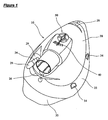
- FIG 1 shows a respiratory mask according to the invention, which is generally designated 10.
- the respiratory mask 10 comprises a mask body 20 and a sealing component 30, which are releasably fastened together.
- the mask body 20 is injection moulded in a relatively rigid plastic material, such as polypropylene, and the sealing component 30 is injection moulded in a more compliant material, such as a thermoplastic elastomeric material.
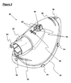
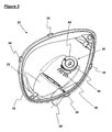
- Figures 2 and 3 show the mask body 20 in isolation from the sealing component 30.
- the mask body 20 is dimensioned and configured to define a cavity that accommodates the nose and mouth of a user, during use, whilst the sealing component 30 seals the mask body 20 against the face of the user.
- the mask body 20 also includes a conventional, tubular connection port 22 for connection of the mask body 20 to a ventilator, and an additional port 24 for connection of the mask body 20 to ancillary apparatus, such as a supplementary supply of oxygen or CO 2 measurement apparatus, if necessary.
- a cap 28 and a guard 29, which are formed of a similar material to the sealing component 30, are also provided, as shown in Figure 1 .
- the cap 28 acts to seal the additional port 24 when not in use, and the guard 29 protects the connection between the additional port 24 and a connected tube, such as an oxygen supply tube, during use.
- a groove 26 is provided at each end of the exterior surface of the mask body 20.
- the grooves 26 are adapted to fasten the mask body 20 to suitable headgear (not shown in the Figures), such as that described in a co-pending UK patent application in the name of the applicant.
- Each groove 26 is orientated transversely relative to the longitudinal axis of the mask 10, and has an entrance opening of slightly reduced width so that an engagement thread of the headgear is received with a snap fit.
- the mask body 20 also includes a peripheral flange 32, which has two projections 34 on each side of the mask body 20 and a recess 36 at each end of the mask body 20. These projections 34 and recesses 36 are each adapted to engage a corresponding formation of the sealing component 30, with a snap fit, thereby fastening the mask body 20 and the sealing component 30 together.
- the mask body 20 also includes a series of six vent openings 40 in a wall of the mask body 20, and an anti-asphyxiation valve 50 adjacent to the vent openings 40.
- the vent openings 40 are adapted to enable carbon dioxide not returned to the breathing circuit through the connection port 22, during use, to escape into the atmosphere.
- the anti-asphyxiation valve 50 is constructed in a wall of the mask body 20, such that the valve 50 is entirely separate from the connection port 22.
- the anti-asphyxiation valve 50 comprises four distinct openings 52 in a wall of the mask body 20, which are arranged in a circular configuration in which the openings are separated by a cross-shaped separator member.
- a deformable valve member 60 is provided, which is injection moulded in a thermoplastic elastomeric material.
- the valve member 60 is adapted to occlude and hence seal the openings 52 in a closed configuration.
- the valve member 60 is generally conical in shape, with a central circular opening, as shown most clearly in Figure 6 .
- the valve member 60 also includes a clearly visible annular rib 64 on one of its major surfaces, in order to indicate the correct configuration of the valve member 60, and also raised indicia 66 that indicate the cavity in which the valve member 60 was manufactured.
- the valve member 60 is mounted to an interior surface of the mask body 20 by a retainer 54 that projects from the centre of the cross-shaped separator member between the openings 52.
- the retainer 54 comprises a cylindrical body with an enlarged head, such that the retainer 54 engages the central opening of the valve member 60 with a snap fit.
- the valve member 60 is not bonded to the retainer 54, but is retained by means of the enlarged head of the retainer 54 having a greater width than the diameter of the opening in the valve member 60.
- the interior surface of the mask body 20 surrounding the four openings 52 is raised relative to the surrounding interior surface of the mask body 20, and defines a valve seat 56 suitable for engagement by the valve member 60 in the closed configuration.
- the valve seat 56 gradually reduces in height towards its outer edge, relative to the retainer 54 and the centre of the valve member 60, and is also slightly concave in form, such that the valve seat 56 is inclined in an opposite direction to the inclination of the valve member 60 in its open configuration.
- the valve member 60 may therefore be deformed into an at least partially inverted configuration in which the valve member lies alongside, and hence engages, the valve seat 56.
- valve member 60 In the open configuration of the valve 50, which is shown in Figures 4 , 5 , 7 and 8 (position A), the valve member 60 is arranged in its inherent conical configuration, such that the valve member 60 is separated from the openings 52 and the associated valve seat 56. In this configuration, gases are able to flow between the mouth of the user and the atmosphere, via the openings 52 of the valve 50. The user is therefore able to breathe atmospheric air when the valve 50 is in its open configuration.
- the valve 50 also includes a flow deflector 58, which is disposed between the valve 50 and the vent openings 40, on the side of the valve 50 that faces the connection port 22. The flow deflector 58 is adapted to shield the valve 50 from the connection port 22, thereby reducing the proportion of gas that flows directly between the connection port 22 and the valve 50 in the open configuration.
- valve member 60 When the pressure differential between the interior of the mask body 20 and atmospheric pressure exceeds a particular threshold, the valve member 60 will be deformed towards the valve seat 56 of the valve 50. In particular, the angle of inclination of the wall of the valve member 60 will reduce. In these transitional configurations, the valve member 60 will be in tension, and these internal stresses will resiliently bias the valve member 60 towards the open configuration. However, further deformation of the valve member 60 caused by the pressure differential will result in the wall of the valve member 60 becoming substantially flat, and then inclined in the opposite direction to its inclination in the open configuration. Beyond a particular threshold, the internal stresses of the valve member 60 will cause it to become resiliently biased into an inverted configuration, and hence into engagement with the valve seat 56 and its closed configuration, as indicated by position B in Figure 8 . In this configuration, the valve member 60 seals the openings 52 of the valve 50 so that airflow between the mask body 20 and the atmosphere, through the valve 50, is prevented.
- the respiratory mask 10 is fitted to a user with the valve 50 in its open configuration, as indicated by position A in Figure 8 .
- the respiratory mask 10 is arranged with the nose and mouth of the user within the cavity defined by the mask body 20, and the sealing component 30 contacting a surrounding area of the user's face.
- Headgear (not shown in the Figures) attached to the respiratory mask 10 urges the sealing component 30 against the user's face in order that an effective seal is provided about the periphery of the respiratory mask 10.
- the connection port 22 is connected to a breathing circuit including a ventilator (not shown in the Figures).
- the valve 50 is therefore adapted to close at a pressure differential, and an airflow into the mask 10, that is greater than that induced by normal, unaided breathing of the user wearing the mask 10.
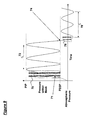
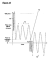
- FIG. 9 An example of the variation of the pressure within the respiratory mask 10 and the airflow into the mask 10 is shown in Figures 9 and 10 , respectively, including initiation of the ventilator and associated breathing circuit, normal ventilator operation (range 72), and unaided breathing through the anti-asphyxiation valve (range 78) following failure of the ventilator (at point 74).
- the airflow into the mask 10 through the connection port 22 will gradually increase beyond the airflow required to maintain a typical Positive End Expiratory Pressure (PEEP), such as approximately 2.0 cmH 2 O (200 Pa), during use.
- PEEP Positive End Expiratory Pressure
- This airflow causes the pressure within the mask 10 to increase, as shown by Figures 9 and 10 , until the pressure within the mask 10 is sufficient to cause the valve member 60 to be deformed from its open configuration into engagement with the valve seat 56 and hence its closed configuration, as indicated by position B in Figure 8 .
- the valve 50 is adapted so that the airflow into the mask 10 required to close the valve 50 is greater than the airflow generated by a user during unaided breathing, and the pressure with the mask 10 required to close the valve 50 is greater than the PEEP of the breathing circuit.
- This closure of the valve 50 may therefore occur at a point within area 70 in Figures 9 and 10 , for example, or indeed at a greater flow or pressure.
- the airflow required to close the valve 50 is approximately 60 Umin (1.0 Ls -1 ), and closure of the valve 50 occurs at point 71 in Figure 9 .
- the pressure within the mask 10 will vary during the user's breathing cycle between approximately the PEEP of the breathing circuit, to a Peak Inspiratory Pressure (PIP), which is typically of the order of 5-50 cmH 2 O (0.5-5 kPa).
- PIP Peak Inspiratory Pressure
- the pressure within the mask and the airflow into the mask will vary as illustrated by range 72 of Figures 9 and 10 .
- the valve 50 will open when the pressure within the mask is at a threshold pressure that is less than atmospheric pressure.
- the valve 50 may open when the pressure within the mask is at a threshold pressure that is equal to, or greater than, atmospheric pressure. In any case, however, the valve 50 will open when the pressure within the mask 10 is at a threshold pressure that is less than the PEEP of the breathing circuit, otherwise the valve 50 would open during normal ventilator operation.
- valve 50 In the open configuration of the valve 50, the user is able to breathe air from the atmosphere through the anti-asphyxiation valve 50. Since the airflow into the mask 10 required to close the valve 50 is greater than the airflow generated by a user during unaided breathing, the valve 50 will remain open until the ventilator becomes operational again.
Landscapes
- Health & Medical Sciences (AREA)
- Pulmonology (AREA)
- Heart & Thoracic Surgery (AREA)
- Engineering & Computer Science (AREA)
- Anesthesiology (AREA)
- Biomedical Technology (AREA)
- Emergency Medicine (AREA)
- Hematology (AREA)
- Life Sciences & Earth Sciences (AREA)
- Animal Behavior & Ethology (AREA)
- General Health & Medical Sciences (AREA)
- Public Health (AREA)
- Veterinary Medicine (AREA)
- Respiratory Apparatuses And Protective Means (AREA)
Claims (14)
- Nichtinvasive Beatmungsschnittstellenvorrichtung, die ein Erstickungsschutzventil (50) mit einer oder mehreren Öffnung(en) (52) zum Ermöglichen des Durchströmens von Gas zwischen dem Beatmungskreislauf und der Atmosphäre und ein Ventilelement (60) aufweist, das zwischen einer offenen Anordnung, in der die eine oder mehreren Öffnung(en) (52) wenigstens teilweise freiliegen und das Durchströmen von Gas durch sie hindurch möglich ist, und einer geschlossenen Anordnung verformbar ist, in der das Ventilelement (60) die eine oder mehreren Öffnung(en) (52) verdeckt und das Durchströmen von Gas durch sie hindurch im Wesentlichen verhindert ist, wobei die eine oder mehreren Öffnung(en) (52) des Erstickungsschutzventils (50) in einer Wand der Schnittstellenvorrichtung ausgebildet sind und das Ventilelement (60) eine ununterbrochene Wand mit einer im Wesentlichen konischen oder pyramidenförmigen Gestalt hat, wobei das Ventilelement (60) so ausgeführt ist, dass die Druckdifferenz zwischen dem Beatmungskreislauf- und dem atmosphärischen Druck, bei der sich das Ventilelement (60) von der offenen Anordnung in die geschlossene Anordnung verformt, größer ist als die Druckdifferenz zwischen dem Beatmungskreislauf und dem atmosphärischen Druck, bei der sich das Ventilelement (60) von der geschlossenen Anordnung in die offene Anordnung verformt, dadurch gekennzeichnet, dass das Ventilelement (60) an der Spitze der konischen oder pyramidenförmigen Wand an einer Innenfläche der Schnittstellenvorrichtung angebracht ist.
- Nichtinvasive Beatmungsschnittstellenvorrichtung nach Anspruch 1, wobei die Schnittstellenvorrichtung eine Atemmaske ist.
- Nichtinvasive Beatmungsschnittstellenvorrichtung nach einem der vorhergehenden Ansprüche, wobei das Ventilelement (60) ein Loch an der Spitze der konischen oder pyramidenförmigen Wand und einen offenen Boden aufweist.
- Nichtinvasive Beatmungsschnittstellenvorrichtung nach einem der vorhergehenden Ansprüche, wobei das Ventilelement (60) dafür ausgelegt ist, in seiner geschlossenen Anordnung wenigstens teilweise umgekehrt zu sein.
- Nichtinvasive Beatmungsschnittstellenvorrichtung nach einem der vorhergehenden Ansprüche, wobei das Ventilelement (60) an einer Innenfläche der Schnittstellenvorrichtung angebracht ist, so dass die Verformung des Ventilelements (60) in seine geschlossene Anordnung verursacht, dass das Ventilelement (60) mit einem Ventilsitz (56) in Eingriff kommt, der die eine oder mehreren Öffnung(en) (52) umgibt.
- Nichtinvasive Beatmungsschnittstellenvorrichtung nach einem der vorhergehenden Ansprüche, wobei das im Wesentlichen konische oder pyramidenförmige Ventilelement (60) mit einer Befestigung (54), die durch ein Loch an der Spitze des Ventilelements (60) verläuft, relativ zu der einen oder den mehreren Öffnung(en) (52) angebracht ist.
- Nichtinvasive Beatmungsschnittstellenvorrichtung nach Anspruch 6, wobei das Ventilelement (60) nicht an die Befestigung (54) angefügt ist.
- Nichtinvasive Beatmungsschnittstellenvorrichtung nach Anspruch 7, wobei die Befestigung (54) einen vergrößerten Kopf mit einer größeren Breite als der Breite des Ventilelementlochs beinhaltet, so dass die Befestigung (54) in das Ventilelement (60) eingeschnappt wird.
- Nichtinvasive Beatmungsschnittstellenvorrichtung nach einem der vorhergehenden Ansprüche, wobei das Ventilelement (60) dafür ausgelegt ist, umgekehrt zu werden, und das Ventilelement (60) eine Anzeige bezüglich der richtigen Anordnung für die Montage des Ventils (50) beinhaltet.
- Nichtinvasive Beatmungsschnittstellenvorrichtung nach einem der vorhergehenden Ansprüche, wobei die Schnittstellenvorrichtung einen Anschluss (22) zur Verbindung der Schnittstellenvorrichtung mit dem Beatmungskreislauf beinhaltet, wobei das Erstickungsschutzventil (50) und der Verbindungsanschluss (22) völlig separate Teile der Schnittstellenvorrichtung sind, die in verschiedenen Teilen der Wand der Schnittstellenvorrichtung ausgebildet sind.
- Nichtinvasive Beatmungsschnittstellenvorrichtung nach Anspruch 10, wobei die Schnittstellenvorrichtung einen Strömungsablenker (58) beinhaltet, der zwischen dem Verbindungsanschluss (22) und dem Erstickungsschutzventil (50) angeordnet ist.
- Nichtinvasive Beatmungsschnittstellenvorrichtung nach Anspruch 11, wobei der Strömungsablenker (58) zum Abschirmen des Erstickungsschutzventils gegen den Verbindungsanschluss (22) ausgeführt ist, wodurch der Gasanteil, der direkt zwischen dem Verbindungsanschluss (22) und dem Erstickungsschutzventil (50) strömt, wenn das Ventilelement (60) in seiner offenen Anordnung ist, verringert wird.
- Nichtinvasive Beatmungsschnittstellenvorrichtung nach einem der vorhergehenden Ansprüche, wobei die Schnittstellenvorrichtung ein oder mehrere Luftlöcher (40) in der Wand der Schnittstellenvorrichtung beinhaltet, die eine Fläche haben, die im Wesentlichen kleiner als die Fläche der einen oder mehreren Öffnung(en) (52) des Erstickungsschutzventils ist.
- Beatmungsvorrichtung, die eine nichtinvasive Beatmungsschnittstellenvorrichtung nach einem der vorhergehenden Ansprüche aufweist.
Applications Claiming Priority (2)
| Application Number | Priority Date | Filing Date | Title |
|---|---|---|---|
| GBGB0722247.4A GB0722247D0 (en) | 2007-11-13 | 2007-11-13 | Improvements relating to anti-asphyxiation valves |
| PCT/GB2008/051056 WO2009063238A1 (en) | 2007-11-13 | 2008-11-13 | Improvements relating to anti-asphyxiation valves |
Publications (2)
| Publication Number | Publication Date |
|---|---|
| EP2229207A1 EP2229207A1 (de) | 2010-09-22 |
| EP2229207B1 true EP2229207B1 (de) | 2013-11-27 |
Family
ID=38896204
Family Applications (1)
| Application Number | Title | Priority Date | Filing Date |
|---|---|---|---|
| EP08850371.9A Active EP2229207B1 (de) | 2007-11-13 | 2008-11-13 | Verbesserungen im zusammenhang mit anti-asphyxationsventilen |
Country Status (6)
| Country | Link |
|---|---|
| US (1) | US8646449B2 (de) |
| EP (1) | EP2229207B1 (de) |
| ES (1) | ES2449394T3 (de) |
| GB (2) | GB0722247D0 (de) |
| PT (1) | PT2229207E (de) |
| WO (1) | WO2009063238A1 (de) |
Families Citing this family (43)
| Publication number | Priority date | Publication date | Assignee | Title |
|---|---|---|---|---|
| US9770611B2 (en) | 2007-05-03 | 2017-09-26 | 3M Innovative Properties Company | Maintenance-free anti-fog respirator |
| US20080271739A1 (en) | 2007-05-03 | 2008-11-06 | 3M Innovative Properties Company | Maintenance-free respirator that has concave portions on opposing sides of mask top section |
| CN102056538B (zh) | 2008-06-06 | 2014-10-15 | 柯惠有限合伙公司 | 用于在换气系统中确定患者努力及/或呼吸参数的系统及方法 |
| EP2295105A1 (de) * | 2009-08-06 | 2011-03-16 | Air Liquide Medical Systems | Nasale Atemmaske mit einem Sauerstoffanschluss, der von einer bewegbaren Klappe geschützt wird |
| EP2515984B8 (de) | 2009-12-23 | 2018-07-25 | Fisher & Paykel Healthcare Limited | Schnittstelle |
| US12194240B2 (en) | 2009-12-23 | 2025-01-14 | Fisher & Paykel Healthcare Limited | Flexible exoskeleton mask with inflating seal member |
| US8714154B2 (en) | 2011-03-30 | 2014-05-06 | Covidien Lp | Systems and methods for automatic adjustment of ventilator settings |
| JP6170036B2 (ja) | 2011-04-15 | 2017-07-26 | フィッシャー アンド ペイケル ヘルスケア リミテッド | ロールする鼻梁部を有するインタフェース |
| US10603456B2 (en) | 2011-04-15 | 2020-03-31 | Fisher & Paykel Healthcare Limited | Interface comprising a nasal sealing portion |
| TWI608850B (zh) | 2011-06-23 | 2017-12-21 | Fisher & Paykel Healthcare Ltd | 包括面罩組件的界面組件 |
| GB2549437B (en) * | 2011-12-09 | 2018-02-28 | Intersurgical Ag | Valve for respiratory masks |
| CN108261596B (zh) | 2012-04-10 | 2021-09-03 | 费雪派克医疗保健有限公司 | 组合式cpap与复苏系统和方法 |
| US10362967B2 (en) | 2012-07-09 | 2019-07-30 | Covidien Lp | Systems and methods for missed breath detection and indication |
| US9950130B2 (en) | 2012-09-04 | 2018-04-24 | Fisher & Paykel Healthcare Limited | Valsalva mask |
| GB2506621B (en) * | 2012-10-03 | 2018-08-08 | Intersurgical Ag | Respiratory mask |
| JP6360485B2 (ja) | 2012-10-17 | 2018-07-18 | フィッシャー アンド ペイケル ヘルスケア リミテッド | 鼻封止部分およびローリングヒンジを備えるインタフェース |
| EP2805748B1 (de) * | 2013-05-24 | 2018-09-26 | Drägerwerk AG & Co. KGaA | Atemmaske mit Notatemventil |
| EP3865168B1 (de) | 2013-08-05 | 2025-11-19 | Fisher & Paykel Healthcare Limited | Schnittstelle |
| US10471230B2 (en) * | 2013-10-11 | 2019-11-12 | Fisher & Paykel Healthcare Limited | HME and compact breathing apparatus |
| US10065011B2 (en) | 2014-05-21 | 2018-09-04 | Atom Medical Corporation | Gas supply mask apparatus |
| EP4245343B1 (de) | 2014-06-17 | 2024-12-25 | Fisher & Paykel Healthcare Limited | Patientenschnittstellen |
| US9808591B2 (en) | 2014-08-15 | 2017-11-07 | Covidien Lp | Methods and systems for breath delivery synchronization |
| CN112121269B (zh) | 2014-08-25 | 2024-08-06 | 费雪派克医疗保健有限公司 | 呼吸面罩及其相关部分、部件或子组件 |
| US9950129B2 (en) | 2014-10-27 | 2018-04-24 | Covidien Lp | Ventilation triggering using change-point detection |
| SG11201703928QA (en) | 2014-11-14 | 2017-06-29 | Fisher & Paykel Healthcare Ltd | Patient interface |
| GB201421618D0 (en) * | 2014-12-04 | 2015-01-21 | 3M Innovative Properties Co | Respirator valve |
| US10682482B2 (en) * | 2014-12-17 | 2020-06-16 | Koninklijke Philips N.V. | Fresh air and anti-asphyxiation assembly |
| GB201508114D0 (en) | 2015-05-12 | 2015-06-24 | 3M Innovative Properties Co | Respirator tab |
| AU2016314605B2 (en) | 2015-09-04 | 2021-05-20 | Fisher & Paykel Healthcare Limited | Patient interfaces |
| WO2017124152A1 (en) * | 2016-01-21 | 2017-07-27 | Resmed Limited | Adjustable headgear tubing for a patient interface |
| CN114904112B (zh) | 2016-10-05 | 2026-02-03 | 费雪派克医疗保健有限公司 | 患者接口 |
| USD823454S1 (en) | 2017-02-23 | 2018-07-17 | Fisher & Paykel Healthcare Limited | Cushion assembly for breathing mask assembly |
| USD824020S1 (en) | 2017-02-23 | 2018-07-24 | Fisher & Paykel Healthcare Limited | Cushion assembly for breathing mask assembly |
| USD823455S1 (en) | 2017-02-23 | 2018-07-17 | Fisher & Paykel Healthcare Limited | Cushion assembly for breathing mask assembly |
| JP7171606B2 (ja) * | 2017-03-28 | 2022-11-15 | コーニンクレッカ フィリップス エヌ ヴェ | フルフェイスマスク用のバルブ装置 |
| WO2018211474A1 (en) | 2017-05-19 | 2018-11-22 | Trudell Medical International | Positive expiratory pressure device |
| CN110869110B (zh) | 2017-07-14 | 2022-11-18 | 3M创新有限公司 | 用于输送多个液体流的适配器 |
| USD884153S1 (en) | 2018-04-04 | 2020-05-12 | Fisher & Paykel Healthcare Limited | Frame for a mask assembly |
| EP3793656A1 (de) | 2018-05-14 | 2021-03-24 | Covidien LP | Systeme und verfahren zur erfassung der atemleistung unter verwendung von signalverzerrung |
| USD903097S1 (en) | 2018-05-18 | 2020-11-24 | Trudell Medical International | Mask |
| USD874064S1 (en) | 2018-05-18 | 2020-01-28 | Trudell Medical International | Mask |
| US11752287B2 (en) | 2018-10-03 | 2023-09-12 | Covidien Lp | Systems and methods for automatic cycling or cycling detection |
| USD893806S1 (en) | 2018-11-09 | 2020-08-18 | Trudell Medical Internationl | Mask and shroud |
Family Cites Families (23)
| Publication number | Priority date | Publication date | Assignee | Title |
|---|---|---|---|---|
| CS178811B2 (en) | 1969-03-20 | 1977-10-31 | Warncke Ernst | Breathing protective mask |
| US4414973A (en) * | 1981-03-10 | 1983-11-15 | U.S.D. Corp. | Respirator face mask |
| US4622964A (en) | 1983-09-28 | 1986-11-18 | O-Two Systems International Inc. | Valve for breathing device |
| US5086768A (en) * | 1987-02-24 | 1992-02-11 | Filcon Corporation | Respiratory protective device |
| US4960121A (en) | 1987-03-18 | 1990-10-02 | Figgie International, Inc. | Half-face mask assembly |
| US4898174A (en) * | 1988-05-03 | 1990-02-06 | Life Support Products, Inc. | Automatic ventilator |
| US4989596A (en) | 1989-02-14 | 1991-02-05 | Macris Allen G | Face chamber |
| WO1994006514A1 (en) | 1992-09-11 | 1994-03-31 | Life Support Products, Inc. | Demand valve with reduced manual flow control |
| US5647355A (en) | 1993-09-30 | 1997-07-15 | Respironics, Inc. | Automatic safety valve for respiratory equipment which is counter-balanced and self-adjusting |
| AUPP855099A0 (en) | 1999-02-09 | 1999-03-04 | Resmed Limited | Gas delivery connection assembly |
| DE29807489U1 (de) | 1998-04-24 | 1998-07-30 | Jaschik, Matthias, Dr., 58644 Iserlohn | Beatmungsmaske |
| DE19818497C1 (de) | 1998-04-24 | 2000-02-24 | Dirk Schulte | Beatmungsmaske |
| US6467483B1 (en) | 1999-07-28 | 2002-10-22 | Respironics, Inc. | Respiratory mask |
| AUPQ382299A0 (en) | 1999-11-03 | 1999-11-25 | Australian Centre For Advanced Medical Technology Ltd | Mask |
| US6530373B1 (en) | 2000-08-04 | 2003-03-11 | Mallinckrodt Inc. | Respirator mask |
| WO2002051486A1 (en) * | 2000-12-22 | 2002-07-04 | Resmed Ltd. | Flow regulation vent |
| US7007696B2 (en) | 2001-05-18 | 2006-03-07 | Tiara Medical Systems, Inc. | Mask cushion and method of using same |
| GB0300875D0 (en) | 2003-01-15 | 2003-02-12 | Smiths Group Plc | Face masks |
| US7559326B2 (en) * | 2003-06-18 | 2009-07-14 | Resmed Limited | Vent and/or diverter assembly for use in breathing apparatus |
| WO2005094928A1 (en) | 2004-04-02 | 2005-10-13 | Fisher & Paykel Healthcare Limited | Breathing assistance apparatus |
| US9295805B2 (en) * | 2005-10-17 | 2016-03-29 | Resmed Limited | Anti-asphyxia valve assembly for respirator mask |
| US8342181B2 (en) * | 2006-06-16 | 2013-01-01 | Resmed Limited | Elbow assembly |
| US8464715B2 (en) * | 2008-04-16 | 2013-06-18 | Stephen Donald Flynn, SR. | Multipurpose therapeutic face mask |
-
2007
- 2007-11-13 GB GBGB0722247.4A patent/GB0722247D0/en not_active Ceased
-
2008
- 2008-11-13 GB GB0820783.9A patent/GB2454790B/en active Active
- 2008-11-13 ES ES08850371.9T patent/ES2449394T3/es active Active
- 2008-11-13 PT PT88503719T patent/PT2229207E/pt unknown
- 2008-11-13 US US12/742,708 patent/US8646449B2/en active Active
- 2008-11-13 WO PCT/GB2008/051056 patent/WO2009063238A1/en not_active Ceased
- 2008-11-13 EP EP08850371.9A patent/EP2229207B1/de active Active
Also Published As
| Publication number | Publication date |
|---|---|
| EP2229207A1 (de) | 2010-09-22 |
| US8646449B2 (en) | 2014-02-11 |
| PT2229207E (pt) | 2014-02-12 |
| US20100263669A1 (en) | 2010-10-21 |
| GB0820783D0 (en) | 2008-12-24 |
| WO2009063238A1 (en) | 2009-05-22 |
| GB0722247D0 (en) | 2007-12-27 |
| ES2449394T3 (es) | 2014-03-19 |
| GB2454790B (en) | 2012-12-05 |
| GB2454790A (en) | 2009-05-20 |
Similar Documents
| Publication | Publication Date | Title |
|---|---|---|
| EP2229207B1 (de) | Verbesserungen im zusammenhang mit anti-asphyxationsventilen | |
| US10272223B2 (en) | Respiratory valve apparatus | |
| US10265496B2 (en) | Anti-asphyxia valve assembly | |
| CN106215297B (zh) | 呼吸面具 | |
| US7066177B2 (en) | Exhalation valves | |
| EP2849828B1 (de) | Dichtungskissen und patientenschnittstellenvorrichtung damit | |
| EP3082925B1 (de) | Anpassbares gesichtsabdichtungssegment für eine atemhilfsvorrichtung und verfahren zur anpassung | |
| US20090095303A1 (en) | Nasal prongs | |
| EP2846862B1 (de) | Patientenschnittstellenvorrichtung mit verformbarer nasengabel | |
| EP3407954B1 (de) | Atemmaske | |
| GB2438083A (en) | Inhalation and exhalation valve for mask | |
| US10682482B2 (en) | Fresh air and anti-asphyxiation assembly | |
| US8893716B2 (en) | Disposable breathing assistance device with manometer | |
| EP3597248B1 (de) | Ventil für atemmasken | |
| EP1663367B1 (de) | Peep-ventil |
Legal Events
| Date | Code | Title | Description |
|---|---|---|---|
| PUAI | Public reference made under article 153(3) epc to a published international application that has entered the european phase |
Free format text: ORIGINAL CODE: 0009012 |
|
| 17P | Request for examination filed |
Effective date: 20100611 |
|
| AK | Designated contracting states |
Kind code of ref document: A1 Designated state(s): AT BE BG CH CY CZ DE DK EE ES FI FR GB GR HR HU IE IS IT LI LT LU LV MC MT NL NO PL PT RO SE SI SK TR |
|
| AX | Request for extension of the european patent |
Extension state: AL BA MK RS |
|
| DAX | Request for extension of the european patent (deleted) | ||
| 17Q | First examination report despatched |
Effective date: 20111027 |
|
| REG | Reference to a national code |
Ref country code: DE Ref legal event code: R079 Ref document number: 602008029027 Country of ref document: DE Free format text: PREVIOUS MAIN CLASS: A61M0016060000 Ipc: A61M0016120000 |
|
| GRAP | Despatch of communication of intention to grant a patent |
Free format text: ORIGINAL CODE: EPIDOSNIGR1 |
|
| RIC1 | Information provided on ipc code assigned before grant |
Ipc: A61M 16/20 20060101ALI20130521BHEP Ipc: A61M 16/06 20060101ALI20130521BHEP Ipc: A61M 16/12 20060101AFI20130521BHEP |
|
| INTG | Intention to grant announced |
Effective date: 20130607 |
|
| GRAS | Grant fee paid |
Free format text: ORIGINAL CODE: EPIDOSNIGR3 |
|
| GRAA | (expected) grant |
Free format text: ORIGINAL CODE: 0009210 |
|
| AK | Designated contracting states |
Kind code of ref document: B1 Designated state(s): AT BE BG CH CY CZ DE DK EE ES FI FR GR HR HU IE IS IT LI LT LU LV MC MT NL NO PL PT RO SE SI SK TR |
|
| RBV | Designated contracting states (corrected) |
Designated state(s): AT BE BG CH CY CZ DE DK EE ES FI FR GR HR HU IE IS IT LI LT LU LV MC MT NL NO PL PT RO SE SI SK TR |
|
| REG | Reference to a national code |
Ref country code: CH Ref legal event code: EP |
|
| REG | Reference to a national code |
Ref country code: AT Ref legal event code: REF Ref document number: 642426 Country of ref document: AT Kind code of ref document: T Effective date: 20131215 |
|
| REG | Reference to a national code |
Ref country code: IE Ref legal event code: FG4D |
|
| REG | Reference to a national code |
Ref country code: DE Ref legal event code: R096 Ref document number: 602008029027 Country of ref document: DE Effective date: 20140123 |
|
| REG | Reference to a national code |
Ref country code: PT Ref legal event code: SC4A Free format text: AVAILABILITY OF NATIONAL TRANSLATION Effective date: 20140131 |
|
| REG | Reference to a national code |
Ref country code: ES Ref legal event code: FG2A Ref document number: 2449394 Country of ref document: ES Kind code of ref document: T3 Effective date: 20140319 Ref country code: NL Ref legal event code: VDEP Effective date: 20131127 |
|
| REG | Reference to a national code |
Ref country code: AT Ref legal event code: MK05 Ref document number: 642426 Country of ref document: AT Kind code of ref document: T Effective date: 20131127 |
|
| REG | Reference to a national code |
Ref country code: LT Ref legal event code: MG4D |
|
| PG25 | Lapsed in a contracting state [announced via postgrant information from national office to epo] |
Ref country code: NO Free format text: LAPSE BECAUSE OF FAILURE TO SUBMIT A TRANSLATION OF THE DESCRIPTION OR TO PAY THE FEE WITHIN THE PRESCRIBED TIME-LIMIT Effective date: 20140227 Ref country code: LT Free format text: LAPSE BECAUSE OF FAILURE TO SUBMIT A TRANSLATION OF THE DESCRIPTION OR TO PAY THE FEE WITHIN THE PRESCRIBED TIME-LIMIT Effective date: 20131127 Ref country code: IS Free format text: LAPSE BECAUSE OF FAILURE TO SUBMIT A TRANSLATION OF THE DESCRIPTION OR TO PAY THE FEE WITHIN THE PRESCRIBED TIME-LIMIT Effective date: 20140327 Ref country code: FI Free format text: LAPSE BECAUSE OF FAILURE TO SUBMIT A TRANSLATION OF THE DESCRIPTION OR TO PAY THE FEE WITHIN THE PRESCRIBED TIME-LIMIT Effective date: 20131127 Ref country code: NL Free format text: LAPSE BECAUSE OF FAILURE TO SUBMIT A TRANSLATION OF THE DESCRIPTION OR TO PAY THE FEE WITHIN THE PRESCRIBED TIME-LIMIT Effective date: 20131127 Ref country code: SE Free format text: LAPSE BECAUSE OF FAILURE TO SUBMIT A TRANSLATION OF THE DESCRIPTION OR TO PAY THE FEE WITHIN THE PRESCRIBED TIME-LIMIT Effective date: 20131127 Ref country code: HR Free format text: LAPSE BECAUSE OF FAILURE TO SUBMIT A TRANSLATION OF THE DESCRIPTION OR TO PAY THE FEE WITHIN THE PRESCRIBED TIME-LIMIT Effective date: 20131127 |
|
| PG25 | Lapsed in a contracting state [announced via postgrant information from national office to epo] |
Ref country code: LV Free format text: LAPSE BECAUSE OF FAILURE TO SUBMIT A TRANSLATION OF THE DESCRIPTION OR TO PAY THE FEE WITHIN THE PRESCRIBED TIME-LIMIT Effective date: 20131127 Ref country code: CY Free format text: LAPSE BECAUSE OF FAILURE TO SUBMIT A TRANSLATION OF THE DESCRIPTION OR TO PAY THE FEE WITHIN THE PRESCRIBED TIME-LIMIT Effective date: 20131127 Ref country code: BE Free format text: LAPSE BECAUSE OF FAILURE TO SUBMIT A TRANSLATION OF THE DESCRIPTION OR TO PAY THE FEE WITHIN THE PRESCRIBED TIME-LIMIT Effective date: 20131127 Ref country code: AT Free format text: LAPSE BECAUSE OF FAILURE TO SUBMIT A TRANSLATION OF THE DESCRIPTION OR TO PAY THE FEE WITHIN THE PRESCRIBED TIME-LIMIT Effective date: 20131127 |
|
| PG25 | Lapsed in a contracting state [announced via postgrant information from national office to epo] |
Ref country code: EE Free format text: LAPSE BECAUSE OF FAILURE TO SUBMIT A TRANSLATION OF THE DESCRIPTION OR TO PAY THE FEE WITHIN THE PRESCRIBED TIME-LIMIT Effective date: 20131127 |
|
| REG | Reference to a national code |
Ref country code: DE Ref legal event code: R097 Ref document number: 602008029027 Country of ref document: DE |
|
| PG25 | Lapsed in a contracting state [announced via postgrant information from national office to epo] |
Ref country code: SK Free format text: LAPSE BECAUSE OF FAILURE TO SUBMIT A TRANSLATION OF THE DESCRIPTION OR TO PAY THE FEE WITHIN THE PRESCRIBED TIME-LIMIT Effective date: 20131127 Ref country code: CZ Free format text: LAPSE BECAUSE OF FAILURE TO SUBMIT A TRANSLATION OF THE DESCRIPTION OR TO PAY THE FEE WITHIN THE PRESCRIBED TIME-LIMIT Effective date: 20131127 Ref country code: RO Free format text: LAPSE BECAUSE OF FAILURE TO SUBMIT A TRANSLATION OF THE DESCRIPTION OR TO PAY THE FEE WITHIN THE PRESCRIBED TIME-LIMIT Effective date: 20131127 Ref country code: PL Free format text: LAPSE BECAUSE OF FAILURE TO SUBMIT A TRANSLATION OF THE DESCRIPTION OR TO PAY THE FEE WITHIN THE PRESCRIBED TIME-LIMIT Effective date: 20131127 |
|
| PG25 | Lapsed in a contracting state [announced via postgrant information from national office to epo] |
Ref country code: DK Free format text: LAPSE BECAUSE OF FAILURE TO SUBMIT A TRANSLATION OF THE DESCRIPTION OR TO PAY THE FEE WITHIN THE PRESCRIBED TIME-LIMIT Effective date: 20131127 |
|
| PLBE | No opposition filed within time limit |
Free format text: ORIGINAL CODE: 0009261 |
|
| STAA | Information on the status of an ep patent application or granted ep patent |
Free format text: STATUS: NO OPPOSITION FILED WITHIN TIME LIMIT |
|
| 26N | No opposition filed |
Effective date: 20140828 |
|
| REG | Reference to a national code |
Ref country code: DE Ref legal event code: R097 Ref document number: 602008029027 Country of ref document: DE Effective date: 20140828 |
|
| PG25 | Lapsed in a contracting state [announced via postgrant information from national office to epo] |
Ref country code: SI Free format text: LAPSE BECAUSE OF FAILURE TO SUBMIT A TRANSLATION OF THE DESCRIPTION OR TO PAY THE FEE WITHIN THE PRESCRIBED TIME-LIMIT Effective date: 20131127 |
|
| PG25 | Lapsed in a contracting state [announced via postgrant information from national office to epo] |
Ref country code: LU Free format text: LAPSE BECAUSE OF FAILURE TO SUBMIT A TRANSLATION OF THE DESCRIPTION OR TO PAY THE FEE WITHIN THE PRESCRIBED TIME-LIMIT Effective date: 20141113 Ref country code: MC Free format text: LAPSE BECAUSE OF FAILURE TO SUBMIT A TRANSLATION OF THE DESCRIPTION OR TO PAY THE FEE WITHIN THE PRESCRIBED TIME-LIMIT Effective date: 20131127 |
|
| REG | Reference to a national code |
Ref country code: CH Ref legal event code: PL |
|
| PG25 | Lapsed in a contracting state [announced via postgrant information from national office to epo] |
Ref country code: LI Free format text: LAPSE BECAUSE OF NON-PAYMENT OF DUE FEES Effective date: 20141130 Ref country code: CH Free format text: LAPSE BECAUSE OF NON-PAYMENT OF DUE FEES Effective date: 20141130 |
|
| REG | Reference to a national code |
Ref country code: IE Ref legal event code: MM4A |
|
| PG25 | Lapsed in a contracting state [announced via postgrant information from national office to epo] |
Ref country code: IE Free format text: LAPSE BECAUSE OF NON-PAYMENT OF DUE FEES Effective date: 20141113 |
|
| REG | Reference to a national code |
Ref country code: FR Ref legal event code: PLFP Year of fee payment: 8 |
|
| PG25 | Lapsed in a contracting state [announced via postgrant information from national office to epo] |
Ref country code: BG Free format text: LAPSE BECAUSE OF FAILURE TO SUBMIT A TRANSLATION OF THE DESCRIPTION OR TO PAY THE FEE WITHIN THE PRESCRIBED TIME-LIMIT Effective date: 20131127 |
|
| PG25 | Lapsed in a contracting state [announced via postgrant information from national office to epo] |
Ref country code: GR Free format text: LAPSE BECAUSE OF FAILURE TO SUBMIT A TRANSLATION OF THE DESCRIPTION OR TO PAY THE FEE WITHIN THE PRESCRIBED TIME-LIMIT Effective date: 20140228 |
|
| PG25 | Lapsed in a contracting state [announced via postgrant information from national office to epo] |
Ref country code: HU Free format text: LAPSE BECAUSE OF FAILURE TO SUBMIT A TRANSLATION OF THE DESCRIPTION OR TO PAY THE FEE WITHIN THE PRESCRIBED TIME-LIMIT; INVALID AB INITIO Effective date: 20081113 Ref country code: TR Free format text: LAPSE BECAUSE OF FAILURE TO SUBMIT A TRANSLATION OF THE DESCRIPTION OR TO PAY THE FEE WITHIN THE PRESCRIBED TIME-LIMIT Effective date: 20131127 Ref country code: MT Free format text: LAPSE BECAUSE OF FAILURE TO SUBMIT A TRANSLATION OF THE DESCRIPTION OR TO PAY THE FEE WITHIN THE PRESCRIBED TIME-LIMIT Effective date: 20131127 |
|
| REG | Reference to a national code |
Ref country code: FR Ref legal event code: PLFP Year of fee payment: 9 |
|
| REG | Reference to a national code |
Ref country code: FR Ref legal event code: PLFP Year of fee payment: 10 |
|
| REG | Reference to a national code |
Ref country code: FR Ref legal event code: PLFP Year of fee payment: 11 |
|
| P01 | Opt-out of the competence of the unified patent court (upc) registered |
Effective date: 20230524 |
|
| PGFP | Annual fee paid to national office [announced via postgrant information from national office to epo] |
Ref country code: PT Payment date: 20250924 Year of fee payment: 18 |
|
| PGFP | Annual fee paid to national office [announced via postgrant information from national office to epo] |
Ref country code: FR Payment date: 20250918 Year of fee payment: 18 |
|
| PGFP | Annual fee paid to national office [announced via postgrant information from national office to epo] |
Ref country code: DE Payment date: 20251021 Year of fee payment: 18 |
|
| PGFP | Annual fee paid to national office [announced via postgrant information from national office to epo] |
Ref country code: IT Payment date: 20251014 Year of fee payment: 18 |
|
| PGFP | Annual fee paid to national office [announced via postgrant information from national office to epo] |
Ref country code: ES Payment date: 20251212 Year of fee payment: 18 |