EP2228333A1 - Simplified fiber tensioning for automated fiber placement machine - Google Patents
Simplified fiber tensioning for automated fiber placement machine Download PDFInfo
- Publication number
- EP2228333A1 EP2228333A1 EP10250405A EP10250405A EP2228333A1 EP 2228333 A1 EP2228333 A1 EP 2228333A1 EP 10250405 A EP10250405 A EP 10250405A EP 10250405 A EP10250405 A EP 10250405A EP 2228333 A1 EP2228333 A1 EP 2228333A1
- Authority
- EP
- European Patent Office
- Prior art keywords
- hub
- fibers
- clutch
- spool
- spring
- Prior art date
- Legal status (The legal status is an assumption and is not a legal conclusion. Google has not performed a legal analysis and makes no representation as to the accuracy of the status listed.)
- Granted
Links
Images

Classifications
-
- B—PERFORMING OPERATIONS; TRANSPORTING
- B29—WORKING OF PLASTICS; WORKING OF SUBSTANCES IN A PLASTIC STATE IN GENERAL
- B29C—SHAPING OR JOINING OF PLASTICS; SHAPING OF MATERIAL IN A PLASTIC STATE, NOT OTHERWISE PROVIDED FOR; AFTER-TREATMENT OF THE SHAPED PRODUCTS, e.g. REPAIRING
- B29C70/00—Shaping composites, i.e. plastics material comprising reinforcements, fillers or preformed parts, e.g. inserts
- B29C70/04—Shaping composites, i.e. plastics material comprising reinforcements, fillers or preformed parts, e.g. inserts comprising reinforcements only, e.g. self-reinforcing plastics
- B29C70/28—Shaping operations therefor
- B29C70/30—Shaping by lay-up, i.e. applying fibres, tape or broadsheet on a mould, former or core; Shaping by spray-up, i.e. spraying of fibres on a mould, former or core
- B29C70/38—Automated lay-up, e.g. using robots, laying filaments according to predetermined patterns
- B29C70/382—Automated fiber placement [AFP]
- B29C70/384—Fiber placement heads, e.g. component parts, details or accessories
-
- B—PERFORMING OPERATIONS; TRANSPORTING
- B65—CONVEYING; PACKING; STORING; HANDLING THIN OR FILAMENTARY MATERIAL
- B65H—HANDLING THIN OR FILAMENTARY MATERIAL, e.g. SHEETS, WEBS, CABLES
- B65H59/00—Adjusting or controlling tension in filamentary material, e.g. for preventing snarling; Applications of tension indicators
- B65H59/02—Adjusting or controlling tension in filamentary material, e.g. for preventing snarling; Applications of tension indicators by regulating delivery of material from supply package
- B65H59/04—Adjusting or controlling tension in filamentary material, e.g. for preventing snarling; Applications of tension indicators by regulating delivery of material from supply package by devices acting on package or support
Definitions
- This disclosure generally relates to automated fiber placement machines, especially those used to layup composite structures, and deals more particularly with a simplified fiber tensioning system.
- AFP machines may be used in the aircraft industry, for example to fabricate structural shapes and skin assemblies by wrapping relatively narrow strips of composite, slit fiber tape or "tows" around a manufacturing tool.
- the AFP machine aligns and places a plurality of the tape strips, typically six or more, in continuous, edge-to-edge contact forming a single wide, conformal bandwidth which is placed on and compacted against the tool.
- AFP machines have been relatively large and complex in order to provide features and functions that allow them to fabricate a wide range of large scale structures.
- the fiber tape is drawn from spools of the tape mounted on the machine. It is necessary to maintain a proper amount of tension on the fiber tape as it is drawn from the spools, and to compensate for slack in the tape which may occur during normal AFP machine operation.
- Tensioning of the fiber tape is controlled by a relatively complicated feedback system that employs a looped network of servo motor drives and sensor arrays.
- Other tensioning systems have employed a rotational drag brake and release mechanism combined with external torsion spring biased rollers to compensate for variations in tape slack.
- a simplified device for maintaining fiber tension and for compensating for fiber slack in fiber placement machines.
- the device allows compact packaging of multiple standard size spools of composite fibers on an AFP head which provides fiber tensioning and slack compensation within each independent hub upon which a spool is mounted.
- a fiber tensioning device for use with a spool of fiber from which fibers are drawn.
- a hub is rotatably mounted on a support and is adapted to have a spool of fibers mounted thereon for rotation on the support.
- Means on the hub apply drag force on the fibers being drawn from the spool in order to maintain tension on the fibers.
- the means for applying drag force may include biasing means for applying a force to the hub in a direction resulting in drag force being applied to the fibers drawn from the spool, and means for limiting the rotational force applied to the hub by the spring.
- the means for limiting the rotational force may include a clutch which includes a clutch disc and a friction pad frictionally engaging the clutch disc.
- a device for maintaining tension on fiber drawn from a spool may be used with an automatic fiber placement system having at least one supply spool of fibers.
- the device includes a rotatable hub adapted to have a supply spool mounted thereon for rotation for the hub. Means are provided in the hub for applying a rotational force on the hub opposing a force applied thereon by fibers being drawn from the spool.
- a method is provided of maintaining tension on fibers being drawn from a fiber supply spool in an automatic fiber placement system.
- the method includes placing the spool on a hub, and using a spring to apply a rotational force to the hub that maintains tension on the fibers being drawn from the spool.
- the method may further comprise using a clutch inside the hub to limit the amount if force applied to the hub by the spring. The clutch may be selectively disengaged to reduce the tension on the fibers being drawn from the spool.
- the disclosed embodiments satisfy the need for a simplified device for tensioning fibers and compensating for fiber slack in a simplified, smaller automatic fiber placement machine employing standard size spools of fiber tape.
- a device for maintaining tension on fibers drawn from the spool comprising:
- the means on the hub for applying the force may include a spring.
- the device may further comprise:
- the means for limiting the force applied to the hub may include a clutch.
- the clutch may include:
- the device may further comprise:
- a device for maintaining tension on fibers drawn from the spool comprising:
- the disclosed embodiments generally relate to a device 20 used to apply tension in fibers and compensate for fiber slack in an automatic fiber placement (AFP) head 46.
- the device 20 includes a hub 22 containing biasing means in the form of a torsion spring 24 which is connected to the hub 22 through a clutch 26 which limits the amount of force applied to the hub 22 by the spring 24.
- the device 20 may optionally include a clutch disengagement device 28 which selectively disengages the clutch 26 in order to suspend the tension applied to the hub 22 by the torsion spring 20.
- a supply spool 30 of fibers is mounted on the hub 22 and the combination of the hub 22 and the supply spool 30 are mounted on a support 32 forming part of the AFP head 46.
- FIG. 2 broadly illustrates the steps of a method of using the device 22 to apply tension in fibers being drawn from the supply spool 30 during an ordinary fiber placement operation performed by the AFP head 46.
- the supply spool 30 is placed on the hub 22.
- a spring 24 is placed inside the hub 22 at 35.
- the torsion spring 24 is connected between the hub 22 and the support 32.
- the torsion spring 24 is used to apply tension to the hub 22.
- the clutch 26 may be used to suspend the tension being applied to the hub 22 by the spring 24.
- the head 42 may include a frame 46 on which there is mounted one or more supply spools 30 of fibers 50.
- fiber and “fibers” refers to composite fibers that may be in the form of composite fiber tape that may be cut into narrow strips which are sometimes referred to as tows, as well as to fiber rovings.
- two supply spools 30 are shown in the drawings, more or less than two spools may be present on the head 42.
- Each of the supply spools 30 is removably supported on a hub 22 for rotation therewith, and feeds fibers 50 to one or more fiber alignment and re-thread mechanisms 44.
- the mechanisms guide the fibers 50 into aligned, side-by-side relationship to form a bandwidth 55 which may be cut by a mechanism 44 and compacted onto a substrate 54 by a compaction roller 52.
- the hub 22 is generally cylindrical in shape and includes an essentially open interior 23.
- a shaft 32 fixed on the frame 46 extends longitudinally through the center of the hub 22 and provides a means for supporting both the hub 22 and the supply spool 30 on the head 42.
- the hub 22 is rotatably mounted on the shaft 32 by means of a pair of bearings 56.
- a helical torsion spring 24 is sleeved over the shaft 32 inside the hub 22 and has one end 27 thereof fixed to the shaft 32 so that end 27 remains stationary.
- the opposite end 29 of the torsion spring 24 is fixed to a clutch disc 26a forming part of a clutch 26 that includes friction pads 26b fixed on the hub 22.
- the spring 24 is compressed between ends 27 and 29 and therefore generates a compressive force that biases the clutch disc 26a in the direction shown by the frictional drag 21 into frictional engagement with the friction pads 26b which may rotate along with the hub 22.
- Initial rotation of the hub 22 results in winding up the torsion spring 24 until the angular torsion force applied to the clutch disc 26a by the spring 24 in the direction shown by the arrow 31 ( FIG. 6 ) overcomes the friction between the clutch disc 26a and the pads 26b, at which point the clutch disc 26a slips relative to the pads 26b as the pads 26b continue to turn.
- the clutch disc 26a frictionally engages the pads 26b to produce frictional drag on hub 22 shown by the arrow 31 in FIG. 6 , in turn applying tension to fibers 50 being drawn off the supply spool 30.
- the spring 24 is maintained concentric with the shaft 32 by a bearing 58 and the end of 29 of the spring 24 that is fixed to the clutch disc 26a.
- the clutch 26 limits the amount of torsional force applied by the spring 24 to the hub 22.
- the frictional drag applied by the spring 24 through the clutch 26 to the hub 22 determines the amount of tension force applied to the fibers 50 being drawn from the supply spool 22.
- a clutch disengagement device 28 discussed below and shown in FIGS. 7-9 , allows disengagement of the clutch disc 26a from the friction pads 26b.
- the spring 24 begins to wind from position A 0 to position A 1 through an angle ⁇ .
- the clutch disc 26a rotates along with the friction pads 26b.
- the rotational force applied to the clutch disc 26a by the spring 24 shown by the frictional drag 31 overcomes the friction 33 between the clutch disc 26a, and the friction pads 26b thus allowing the clutch disc 26a to slip in the direction 31 relative to the pads 26b.
- Angular displacement of the spool 22 through the angle ⁇ allows the fibers to advance to position P 1 .
- the advancement of the fibers 50 to point P 2 corresponds to the angular displacement at A 2 where the clutch disc 26a begins to slip.
- the force F applied to the fibers 50 will be equal to the rotational restraining moment between the clutch disc 26a and the compressive force applied by the spring 24 to the clutch disc 26a.
- the resulting slack in the fibers 50 is taken up by the torsion spring 24.
- a cylindrically shaped clutch deactivation device 28 may be optionally provided in order to disengage the clutch 26 where it is desired, for example to reduce the drag force on the fibers 50 during start-up of the head 42, or when the placement of a new tape bandwidth 55 is about to be commenced.
- the clutch deactivation device 28 is generally cylindrical in shape and includes an end wall 28a disposed outside of the hub 22. The sides 28b of the device 28 slide through the hub 22 so that the end 28c of the device 28 may engage the periphery of the clutch disc 26a.
- Embodiments of the disclosure may find use in a variety of potential applications, particularly in the transportation industry, including for example, aerospace, marine and automotive applications.
- exemplary method 62 may include specification and design 66 of the aircraft 64 and material procurement 68.
- component and subassembly manufacturing 70 and system integration 72 of the aircraft 62 takes place.
- the simplified tensioning device 20 may be used in an AFP machine employed to fabricate composite structures forming components or subassemblies that are assembled at 70 or integrated as part of a system at 72.
- the aircraft 64 may go through certification and delivery 56 in order to be placed in service 76. While in service by a customer, the aircraft 64 is scheduled for routine maintenance and service 78 (which may also include modification, reconfiguration, refurbishment, and so on).
- routine maintenance and service 78 (which may also include modification, reconfiguration, refurbishment, and so on).
- the simplified tensioning device may be used in an AFP machine employed to fabricate replacement parts or components used in the maintenance and service 78.
- Each of the processes of method 62 may be performed or carried out by a system integrator, a third party, and/or an operator (e.g., a customer).
- a system integrator may include without limitation any number of aircraft manufacturers and major-system subcontractors
- a third party may include without limitation any number of vendors, subcontractors, and suppliers
- an operator may be an airline, leasing company, military entity, service organization, and so on.
- the aircraft 64 produced by exemplary method 62 may include an airframe 80 with a plurality of systems 82 and an interior 84.
- high-level systems 82 include one or more of a propulsion system 86, an electrical system 88, a hydraulic system 90, and an environmental system 92. Any number of other systems may be included.
- an aerospace example is shown, the principles of the disclosure may be applied to other industries, such as the marine and automotive industries.
- Systems and methods embodied herein may be employed during any one or more of the stages of the production and service method 62.
- components or subassemblies corresponding to production process 70 may be fabricated or manufactured in a manner similar to components or subassemblies produced while the aircraft 64 is in service.
- one or more apparatus embodiments, method embodiments, or a combination thereof may be utilized during the production stages 70 and 72, for example, by substantially expediting assembly of or reducing the cost of an aircraft 64.
- apparatus embodiments, method embodiments, or a combination thereof may be utilized while the aircraft 64 is in service, for example and without limitation, to maintenance and service 78.
Landscapes
- Engineering & Computer Science (AREA)
- Robotics (AREA)
- Chemical & Material Sciences (AREA)
- Composite Materials (AREA)
- Mechanical Engineering (AREA)
- Moulding By Coating Moulds (AREA)
- Tension Adjustment In Filamentary Materials (AREA)
Abstract
Description
- This disclosure generally relates to automated fiber placement machines, especially those used to layup composite structures, and deals more particularly with a simplified fiber tensioning system.
- Composite structures such as those used in the automotive, marine and aerospace industries may be fabricated using automated composite material application machines, commonly referred to as automated fiber placement (AFP) machines. AFP machines may be used in the aircraft industry, for example to fabricate structural shapes and skin assemblies by wrapping relatively narrow strips of composite, slit fiber tape or "tows" around a manufacturing tool. The AFP machine aligns and places a plurality of the tape strips, typically six or more, in continuous, edge-to-edge contact forming a single wide, conformal bandwidth which is placed on and compacted against the tool.
- In the past, AFP machines have been relatively large and complex in order to provide features and functions that allow them to fabricate a wide range of large scale structures. During tape placement, the fiber tape is drawn from spools of the tape mounted on the machine. It is necessary to maintain a proper amount of tension on the fiber tape as it is drawn from the spools, and to compensate for slack in the tape which may occur during normal AFP machine operation. Tensioning of the fiber tape is controlled by a relatively complicated feedback system that employs a looped network of servo motor drives and sensor arrays. Other tensioning systems have employed a rotational drag brake and release mechanism combined with external torsion spring biased rollers to compensate for variations in tape slack.
- More recently, smaller, simplified AFP machines have been proposed that are capable of placing narrower fiber tows, and are therefore may be better suited for fabricating smaller structures and components. Although the mechanisms used in the fiber placement heads of these simplified AFP machines are smaller and have reduced complexity, the machines nevertheless utilize standard size spools of composite fiber tape of the type discussed above. The use of known, relatively complicated fiber tensioning systems may not be compatible with these smaller AFP machines.
- Accordingly, there is a need for a simplified fiber tensioning device that may be used with simplified AFP machines using standard size spools of tape.
- According to the disclosed embodiments, a simplified device is provided for maintaining fiber tension and for compensating for fiber slack in fiber placement machines. The device allows compact packaging of multiple standard size spools of composite fibers on an AFP head which provides fiber tensioning and slack compensation within each independent hub upon which a spool is mounted.
- According to one embodiment, a fiber tensioning device is provided for use with a spool of fiber from which fibers are drawn. A hub is rotatably mounted on a support and is adapted to have a spool of fibers mounted thereon for rotation on the support. Means on the hub apply drag force on the fibers being drawn from the spool in order to maintain tension on the fibers. The means for applying drag force may include biasing means for applying a force to the hub in a direction resulting in drag force being applied to the fibers drawn from the spool, and means for limiting the rotational force applied to the hub by the spring. The means for limiting the rotational force may include a clutch which includes a clutch disc and a friction pad frictionally engaging the clutch disc.
- According to another embodiment, a device for maintaining tension on fiber drawn from a spool may be used with an automatic fiber placement system having at least one supply spool of fibers. The device includes a rotatable hub adapted to have a supply spool mounted thereon for rotation for the hub. Means are provided in the hub for applying a rotational force on the hub opposing a force applied thereon by fibers being drawn from the spool.
- According to a further embodiment, a method is provided of maintaining tension on fibers being drawn from a fiber supply spool in an automatic fiber placement system. The method includes placing the spool on a hub, and using a spring to apply a rotational force to the hub that maintains tension on the fibers being drawn from the spool. The method may further comprise using a clutch inside the hub to limit the amount if force applied to the hub by the spring. The clutch may be selectively disengaged to reduce the tension on the fibers being drawn from the spool.
- The disclosed embodiments satisfy the need for a simplified device for tensioning fibers and compensating for fiber slack in a simplified, smaller automatic fiber placement machine employing standard size spools of fiber tape.
- Also disclosed is, for use with an automatic fiber placement system having at least one supply spool of fibers, a device for maintaining tension on fibers drawn from the spool, comprising:
- a rotatable hub adapted to have the supply spool mounted thereon for rotation with the hub; and
- means in the hub for applying a rotational force on the hub opposing a force applied to the hub by fibers being drawn from the spool.
- The means on the hub for applying the force may include a spring.
- The device may further comprise:
- means in the hub for limiting the force applied to the hub by the means for applying force.
- The means for limiting the force applied to the hub may include a clutch.
- The clutch may include:
- a clutch disc, and
- a clutch pad frictionally engaging the clutch disc.
- The device may further comprise:
- means for disengaging the clutch.
- Also disclosed is, for use with an automatic fiber placement system having at least one supply spool of fibers, a device for maintaining tension on fibers drawn from the spool, comprising:
- a shaft;
- a hub adapted to have the spool mounted thereon;
- means including bearings for mounting the hub for rotation on the shaft;
- a spring sleeved over the shaft inside the hub, the spring having a first end secured to the shaft and having a second end;
- a clutch within the hub and coupled between the second end of the spring and the hub; and
- means on the hub for disengaging the clutch.
- Also disclosed is a method of maintaining tension on fibers being drawn from a fiber supply spool in an automatic fiber placement system, comprising:
- placing the spool on a hub;
- connecting a spring with the hub through a clutch;
- using the spring to apply a rotational force to the hub keeping the fibers in tension;
- using the clutch to limit the rotational force applied to the hub by the spring;
- placing a clutch disengagement device on the hub; and
- using the clutch disengagement device to selectively disengage the spring from the hub.
-
-
FIG. 1 is an illustration of a functional block diagram of a simplified fiber tensioning device according to the disclosed embodiments. -
FIG. 2 is an illustration of a flow diagram showing the overall steps of a method for maintaining tension on fibers being drawn from a supply spool. -
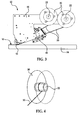
FIG. 3 is an illustration of a side view of a reduced complexity fiber placement head employing standard size spools of fibers and a simplified fiber tensioning device. -
FIG. 4 is an illustration of a diagrammatic, perspective view of one of the spools shown inFIG. 3 , mounted on a hub. -
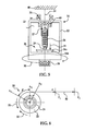
FIG. 5 is an illustration of a longitudinal sectional view of the hub shown inFIG. 4 . -
FIG. 6 is an illustration of an end view of the hub shown inFIG. 5 . -
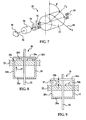
FIG. 7 is an illustration of an exploded, perspective view of the hub shown inFIGS. 5 and 6 . -
FIG. 8 is an illustration of a sectional view of the clutch disengagement device, showing the clutch in its engaged position. -
FIG. 9 is an illustration of a sectional view similar toFIG. 8 but showing the disengagement device having disengaged the clutch. -
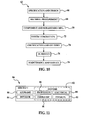
FIG. 10 is an illustration of a flow diagram of aircraft production and service methodology. -
FIG. 11 is an illustration of a block diagram of an aircraft. - Referring first to
FIG. 1 , the disclosed embodiments generally relate to adevice 20 used to apply tension in fibers and compensate for fiber slack in an automatic fiber placement (AFP)head 46. Thedevice 20 includes ahub 22 containing biasing means in the form of atorsion spring 24 which is connected to thehub 22 through a clutch 26 which limits the amount of force applied to thehub 22 by thespring 24. Thedevice 20 may optionally include aclutch disengagement device 28 which selectively disengages the clutch 26 in order to suspend the tension applied to thehub 22 by thetorsion spring 20. Asupply spool 30 of fibers is mounted on thehub 22 and the combination of thehub 22 and thesupply spool 30 are mounted on asupport 32 forming part of theAFP head 46. -
FIG. 2 broadly illustrates the steps of a method of using thedevice 22 to apply tension in fibers being drawn from thesupply spool 30 during an ordinary fiber placement operation performed by theAFP head 46. Beginning at 34, thesupply spool 30 is placed on thehub 22. Aspring 24 is placed inside thehub 22 at 35. At 36, thetorsion spring 24 is connected between thehub 22 and thesupport 32. At 38, thetorsion spring 24 is used to apply tension to thehub 22. Finally, at 40, the clutch 26 may be used to suspend the tension being applied to thehub 22 by thespring 24. - Attention is now directed to
FIGS. 3 and 4 which illustrate further details of theAFP head 42 and supply spools 30. Thehead 42 may include aframe 46 on which there is mounted one or more supply spools 30 offibers 50. As used herein, "fiber" and "fibers" refers to composite fibers that may be in the form of composite fiber tape that may be cut into narrow strips which are sometimes referred to as tows, as well as to fiber rovings. Although twosupply spools 30 are shown in the drawings, more or less than two spools may be present on thehead 42. Each of the supply spools 30 is removably supported on ahub 22 for rotation therewith, and feedsfibers 50 to one or more fiber alignment andre-thread mechanisms 44. The mechanisms guide thefibers 50 into aligned, side-by-side relationship to form abandwidth 55 which may be cut by amechanism 44 and compacted onto asubstrate 54 by acompaction roller 52. - Attention is now directed to
FIGS. 5, 6 and7 which illustrate further details of thedevice 20. Thehub 22 is generally cylindrical in shape and includes an essentiallyopen interior 23. Ashaft 32 fixed on theframe 46 extends longitudinally through the center of thehub 22 and provides a means for supporting both thehub 22 and thesupply spool 30 on thehead 42. Thehub 22 is rotatably mounted on theshaft 32 by means of a pair ofbearings 56. - A
helical torsion spring 24 is sleeved over theshaft 32 inside thehub 22 and has oneend 27 thereof fixed to theshaft 32 so thatend 27 remains stationary. Theopposite end 29 of thetorsion spring 24 is fixed to aclutch disc 26a forming part of a clutch 26 that includesfriction pads 26b fixed on thehub 22. Thespring 24 is compressed between ends 27 and 29 and therefore generates a compressive force that biases theclutch disc 26a in the direction shown by thefrictional drag 21 into frictional engagement with thefriction pads 26b which may rotate along with thehub 22. Initial rotation of thehub 22 results in winding up thetorsion spring 24 until the angular torsion force applied to theclutch disc 26a by thespring 24 in the direction shown by the arrow 31 (FIG. 6 ) overcomes the friction between theclutch disc 26a and thepads 26b, at which point theclutch disc 26a slips relative to thepads 26b as thepads 26b continue to turn. - As
hub 22 rotates onshaft 32, theclutch disc 26a frictionally engages thepads 26b to produce frictional drag onhub 22 shown by thearrow 31 inFIG. 6 , in turn applying tension tofibers 50 being drawn off thesupply spool 30. Thespring 24 is maintained concentric with theshaft 32 by abearing 58 and the end of 29 of thespring 24 that is fixed to theclutch disc 26a. The clutch 26 limits the amount of torsional force applied by thespring 24 to thehub 22. The frictional drag applied by thespring 24 through the clutch 26 to thehub 22 determines the amount of tension force applied to thefibers 50 being drawn from thesupply spool 22. Although not shown inFIGS. 5 and 6 , aclutch disengagement device 28 discussed below and shown inFIGS. 7-9 , allows disengagement of theclutch disc 26a from thefriction pads 26b. - Referring particularly to
FIG. 6 as thefibers 50 are slowly drawn from thespool 22, thespring 24 begins to wind from position A0 to position A1 through an angle β. During angular rotation through β, theclutch disc 26a rotates along with thefriction pads 26b. However when the rotation of thespool 22 advances to the position shown as A2, the rotational force applied to theclutch disc 26a by thespring 24 shown by thefrictional drag 31 overcomes thefriction 33 between theclutch disc 26a, and thefriction pads 26b thus allowing theclutch disc 26a to slip in thedirection 31 relative to thepads 26b. - Angular displacement of the
spool 22 through the angle β allows the fibers to advance to position P1. The advancement of thefibers 50 to point P2 corresponds to the angular displacement at A2 where theclutch disc 26a begins to slip. When thefibers 50 advance from P1 to P2, the force F applied to thefibers 50 will be equal to the rotational restraining moment between theclutch disc 26a and the compressive force applied by thespring 24 to theclutch disc 26a. In the event that the advancement of thefibers 50 is stopped and retracted from position P2 to position P1, the resulting slack in thefibers 50 is taken up by thetorsion spring 24. - Referring now also to
FIGS. 7-9 , a cylindrically shapedclutch deactivation device 28 may be optionally provided in order to disengage the clutch 26 where it is desired, for example to reduce the drag force on thefibers 50 during start-up of thehead 42, or when the placement of anew tape bandwidth 55 is about to be commenced. As best seen inFIG. 8 , theclutch deactivation device 28 is generally cylindrical in shape and includes anend wall 28a disposed outside of thehub 22. Thesides 28b of thedevice 28 slide through thehub 22 so that theend 28c of thedevice 28 may engage the periphery of theclutch disc 26a. Thus, by sliding thedevice 28 axially 37 into thehub 22, the force applied to theclutch disc 26a by thespring 24 is overcome, allowing theclutch disc 26a to be displaced along the shaft 32 a distance "D" (FIG. 9 ), which in turn disengages theclutch disc 26a from thefriction pads 26b. Due to the spring loading provided byspring 24, releasing thedevice 28 results in thespring 24 forcing theclutch disc 26a back into frictional engagement with thefriction pads 28b. - Embodiments of the disclosure may find use in a variety of potential applications, particularly in the transportation industry, including for example, aerospace, marine and automotive applications. Thus, referring now to
FIGS. 10 and 11 , embodiments of the disclosure may be used in the context of an aircraft manufacturing andservice method 62 as shown inFigure 10 and anaircraft 64 as shown inFigure 11 . During pre-production,exemplary method 62 may include specification anddesign 66 of theaircraft 64 andmaterial procurement 68. During production, component andsubassembly manufacturing 70 andsystem integration 72 of theaircraft 62 takes place. Thesimplified tensioning device 20 may be used in an AFP machine employed to fabricate composite structures forming components or subassemblies that are assembled at 70 or integrated as part of a system at 72. Thereafter, theaircraft 64 may go through certification anddelivery 56 in order to be placed inservice 76. While in service by a customer, theaircraft 64 is scheduled for routine maintenance and service 78 (which may also include modification, reconfiguration, refurbishment, and so on). The simplified tensioning device may be used in an AFP machine employed to fabricate replacement parts or components used in the maintenance andservice 78. - Each of the processes of
method 62 may be performed or carried out by a system integrator, a third party, and/or an operator (e.g., a customer). For the purposes of this description, a system integrator may include without limitation any number of aircraft manufacturers and major-system subcontractors; a third party may include without limitation any number of vendors, subcontractors, and suppliers; and an operator may be an airline, leasing company, military entity, service organization, and so on. - As shown in
FIG. 11 , theaircraft 64 produced byexemplary method 62 may include anairframe 80 with a plurality ofsystems 82 and an interior 84. Examples of high-level systems 82 include one or more of apropulsion system 86, anelectrical system 88, ahydraulic system 90, and anenvironmental system 92. Any number of other systems may be included. Although an aerospace example is shown, the principles of the disclosure may be applied to other industries, such as the marine and automotive industries. - Systems and methods embodied herein may be employed during any one or more of the stages of the production and
service method 62. For example, components or subassemblies corresponding toproduction process 70 may be fabricated or manufactured in a manner similar to components or subassemblies produced while theaircraft 64 is in service. Also, one or more apparatus embodiments, method embodiments, or a combination thereof may be utilized during the production stages 70 and 72, for example, by substantially expediting assembly of or reducing the cost of anaircraft 64. Similarly, one or more of apparatus embodiments, method embodiments, or a combination thereof may be utilized while theaircraft 64 is in service, for example and without limitation, to maintenance andservice 78. - Although the embodiments of this disclosure have been described with respect to certain exemplary embodiments, it is to be understood that the specific embodiments are for purposes of illustration and not limitation, as other variations will occur to those of skill in the art.
Claims (12)
- A fiber tensioning device for use with a spool of fiber from which fibers are drawn, comprising:a support;a hub rotatably mounted on the support, the hub being adapted to have the spool of fibers mounted thereon for rotation therewith on the support; andmeans on the hub for applying drag force on fibers being drawn from the spool.
- The device of claim 1, wherein the means for applying drag force includes:biasing means for biasing the hub in a direction resulting in the drag force being applied to the fibers drawn from the spool; andmeans for limiting the drag force applied to the hub by the biasing means.
- The device of claim 2, wherein:the support includes a shaft,the biasing means includes a spring mounted between the hub and the shaft.
- The device of claim 3, wherein the spring is sleeved over the shaft.
- The device of claim 1, wherein the means for limiting the force includes a clutch.
- The device of claim 5, wherein the clutch includes:a clutch disc, anda friction pad frictionally engaging the clutch disc.
- The device of claim 5, wherein:the biasing means includes a spring,the clutch disc is connected to the spring, andthe friction pad is mounted on the hub.
- The device of claim 5, further comprising:means on the hub for disengaging the clutch.
- A method of maintaining tension on fibers being drawn from a fiber supply spool on an automatic fiber placement machine, comprising:placing the spool on a hub; andusing a spring within the hub to apply a rotational force to the hub that maintains tension on the fibers being drawn from the spool.
- The method of claim 9, further comprising:using a clutch within the hub to limit the rotational force applied to the hub by the spring.
- The method of claim 10, further comprising:selectively disengaging the clutch to reduce the tension on the fibers being drawn from the spool.
- The method of claim 11, wherein selectively disengaging the clutch is performed by displacing a clutch disengagement device on the hub.
Applications Claiming Priority (1)
| Application Number | Priority Date | Filing Date | Title |
|---|---|---|---|
| US12/400,600 US8308101B2 (en) | 2009-03-09 | 2009-03-09 | Simplified fiber tensioning for automated fiber placement machines |
Publications (2)
| Publication Number | Publication Date |
|---|---|
| EP2228333A1 true EP2228333A1 (en) | 2010-09-15 |
| EP2228333B1 EP2228333B1 (en) | 2015-02-25 |
Family
ID=42124282
Family Applications (1)
| Application Number | Title | Priority Date | Filing Date |
|---|---|---|---|
| EP10250405.7A Active EP2228333B1 (en) | 2009-03-09 | 2010-03-05 | Simplified fiber tensioning for automated fiber placement machine |
Country Status (5)
| Country | Link |
|---|---|
| US (2) | US8308101B2 (en) |
| EP (1) | EP2228333B1 (en) |
| JP (1) | JP5566729B2 (en) |
| ES (1) | ES2537115T3 (en) |
| PT (1) | PT2228333E (en) |
Cited By (9)
| Publication number | Priority date | Publication date | Assignee | Title |
|---|---|---|---|---|
| US8272419B2 (en) | 2008-01-02 | 2012-09-25 | The Boeing Company | Graphite tape supply and backing paper take-up apparatus |
| US8308101B2 (en) | 2009-03-09 | 2012-11-13 | The Boeing Company | Simplified fiber tensioning for automated fiber placement machines |
| US8345269B2 (en) | 2007-09-22 | 2013-01-01 | The Boeing Company | Method and apparatus for measuring the width of composite tape |
| US8454788B2 (en) | 2009-03-13 | 2013-06-04 | The Boeing Company | Method and apparatus for placing short courses of composite tape |
| US8464773B2 (en) | 2007-07-27 | 2013-06-18 | The Boeing Company | Tape removal apparatus and process |
| US8557074B2 (en) | 2008-02-27 | 2013-10-15 | The Boeing Company | Reduced complexity automatic fiber placement apparatus and method |
| EP3000340A1 (en) * | 2014-09-25 | 2016-03-30 | Gerhard Ofer | Thread feeding apparatus |
| CN106133465A (en) * | 2014-03-24 | 2016-11-16 | B/E航空公司 | There is the vehicles refrigeration plant of liquid cooling system |
| WO2017203109A1 (en) * | 2016-05-26 | 2017-11-30 | Coriolis Composites | Machine for applying continuous fibres comprising a braking device positioned in the application head and method implementing such a machine |
Families Citing this family (12)
| Publication number | Priority date | Publication date | Assignee | Title |
|---|---|---|---|---|
| US8986482B2 (en) | 2008-07-08 | 2015-03-24 | The Boeing Company | Method and apparatus for producing composite structures |
| US20120073738A1 (en) | 2010-09-29 | 2012-03-29 | The Boeing Company | Method and apparatus for laying up barrel-shaped composite structures |
| US8808490B2 (en) | 2011-08-04 | 2014-08-19 | The Boeing Company | Methods for laminating composites |
| CN104163358B (en) * | 2013-05-20 | 2017-12-29 | 尹锡枝 | Wrapping machine tension compensator |
| US9545759B2 (en) | 2015-01-30 | 2017-01-17 | CGTech | Automated fiber placement with course trajectory compensation |
| US10513101B2 (en) * | 2015-03-13 | 2019-12-24 | The Boeing Company | Apparatuses and methods for creating layered tape composite structures |
| US9868259B2 (en) | 2015-09-18 | 2018-01-16 | General Electric Company | Fiber placement machine roller with vacuum assisted tow handling |
| DE102015121428B4 (en) * | 2015-12-09 | 2019-10-31 | Deutsches Zentrum für Luft- und Raumfahrt e.V. | Fiber-laying head and fiber-laying plant and method for producing a fiber-composite component |
| CN105836517B (en) * | 2016-05-24 | 2017-12-08 | 中山市川成精密电子有限公司 | Forming equipment with independent feeding and automatic combination functions and control process |
| US11167951B2 (en) * | 2016-06-30 | 2021-11-09 | Robert Bosch Tool Corporation | Automatic mechanical spool changer for 3-D printers |
| US10814570B2 (en) * | 2018-11-01 | 2020-10-27 | The Boeing Company | Self-threading lamination head and method |
| KR20230121031A (en) | 2020-09-17 | 2023-08-17 | 아이코맷 리미티드 | tape placement head |
Citations (6)
| Publication number | Priority date | Publication date | Assignee | Title |
|---|---|---|---|---|
| DE2505223A1 (en) * | 1975-02-06 | 1976-08-19 | Siemens Ag | Wire unreeling appts with hollow cylinder - has two flanges forming spool fitted with brake and rewind mechanism |
| US4462551A (en) * | 1982-08-13 | 1984-07-31 | Paul Bloch | Retractible fly tying bobbin |
| US4706442A (en) * | 1986-05-27 | 1987-11-17 | Highlight Industries, Inc. | Stretch film wrapping device |
| US5000397A (en) | 1988-04-25 | 1991-03-19 | Aerospatiale Societe Nationale Industrielle | Cassette for the storage and dispensing of thread or ribbon at a preset tension |
| US5725175A (en) * | 1994-06-20 | 1998-03-10 | The Miller Group, Ltd. | Single tension adjustment for dual wire rolls |
| JP2006347121A (en) * | 2005-06-20 | 2006-12-28 | Mitsuboshi Belting Ltd | Belt core wire supply apparatus |
Family Cites Families (205)
| Publication number | Priority date | Publication date | Assignee | Title |
|---|---|---|---|---|
| US1195554A (en) | 1916-08-22 | buurdinx | ||
| US799374A (en) | 1903-10-05 | 1905-09-12 | Christian Hamilton Gray | Rubber fabric. |
| US920776A (en) | 1908-12-18 | 1909-05-04 | Edward Pohl | Silk-thread-finishing machine. |
| US1132837A (en) | 1912-12-09 | 1915-03-23 | Nat Tape Company Inc | Apparatus for producing tape, string, and the like. |
| US1464632A (en) | 1918-04-15 | 1923-08-14 | Herbert N Wayne | Process of embedding cords in rubber |
| US1370339A (en) | 1919-12-10 | 1921-03-01 | Fisk Rubber Co | Method of covering strands with rubber |
| US1420271A (en) | 1921-03-30 | 1922-06-20 | Joseph A Mclane | Method and apparatus for producing weftless cloth |
| US1420277A (en) | 1921-08-15 | 1922-06-20 | Mortimer L Packer | Fuel mixer |
| US1512096A (en) | 1923-11-03 | 1924-10-21 | Hopkinson Ernest | Process and apparatus for manufacturing weftless fabric |
| US1930733A (en) * | 1930-12-30 | 1933-10-17 | Hoe & Co R | Web roll controlling mechanism |
| US2182358A (en) | 1934-12-22 | 1939-12-05 | Pittsburgh Plate Glass Co | Apparatus for making safety glass |
| US2220760A (en) | 1939-05-22 | 1940-11-05 | Gates Rubber Co | Machine for uniformly spacing parallel cords |
| US2345541A (en) | 1941-08-22 | 1944-03-28 | Robertson Bleachery & Dye Work | Polymerization of synthetic resin impregnated fabrics |
| US2722590A (en) | 1951-06-12 | 1955-11-01 | Gen Tire & Rubber Co | Tube joining apparatus |
| DE1155846B (en) | 1955-04-29 | 1963-10-17 | Herbert Lindner Fa | Device for setting measuring sections by limiting the adjustment movement of the slide on machine tools, for example coordinate drilling machines |
| US3037898A (en) | 1957-05-17 | 1962-06-05 | Wabor A G Fa | Manufacture of floor coverings |
| US3137452A (en) * | 1961-09-14 | 1964-06-16 | Robert F Winders | Mechanism for delivering wire from a coil thereof |
| US3329181A (en) | 1965-01-08 | 1967-07-04 | Broyhill Furniture Factories | Apparatus and method for cutting assorted lengths from material having irregular and random defects |
| US3574040A (en) | 1967-06-29 | 1971-04-06 | Gen Dynamics Corp | Apparatus for making laminated structural shapes by the controlled detrusive placement and polymerization of tectonic filamentous tapes |
| US3602416A (en) | 1969-01-29 | 1971-08-31 | United Aircraft Corp | Method of collimating fibers |
| US3684278A (en) | 1969-12-16 | 1972-08-15 | Isao Takahaski | Apparatus for the automatic separation of a negative sheet and a photosensitive sheet from the stack of them on a photocopier |
| US3695977A (en) | 1970-03-17 | 1972-10-03 | David Georgievich Kandelaki | Device to produce nonwoven continuous ribbons from threads |
| US3775219A (en) | 1971-04-05 | 1973-11-27 | Goldsworthy Eng Inc | Composite-tape placement head |
| US3844822A (en) | 1971-12-23 | 1974-10-29 | Celanese Corp | Production of uniformly resin impregnated carbon fiber ribbon |
| US3810805A (en) | 1972-04-14 | 1974-05-14 | Goldsworthy Eng Inc | Geodesic path length compensator for composite-tape placement head |
| JPS5119036Y2 (en) * | 1972-05-25 | 1976-05-19 | ||
| US3970831A (en) | 1974-02-11 | 1976-07-20 | Goldsworthy Engineering, Inc. | Digitizing system for tape placement apparatus |
| US3910522A (en) | 1974-09-18 | 1975-10-07 | Worldwide Converting Mach | Web tension control system |
| US3992240A (en) | 1975-05-19 | 1976-11-16 | The Boeing Company | Method and apparatus for fabricating elongate laminated structures |
| US4091979A (en) | 1976-03-29 | 1978-05-30 | Bell & Howell Company | Methods and apparatus for precision guiding a web |
| US4100004A (en) | 1976-05-11 | 1978-07-11 | Securicum S.A. | Method of making carbon fibers and resin-impregnated carbon fibers |
| US4051774A (en) | 1976-05-17 | 1977-10-04 | Jack Barnes Engineering, Inc. | Machine for printing measuring tapes |
| US4208238A (en) | 1977-07-11 | 1980-06-17 | Grumman Aerospace Corporation | Gantry for use in the manufacture of laminar structures |
| US4133711A (en) | 1977-07-11 | 1979-01-09 | Grumman Aerospace Corporation | Automated integrated composite lamination system |
| US4328061A (en) | 1977-10-25 | 1982-05-04 | Haggar Company | Apparatus for depositing adhesive strips |
| US4186861A (en) * | 1978-08-03 | 1980-02-05 | Orion Machinery And Engineering Corporation | Wire accumulator tower |
| US4234374A (en) | 1978-10-10 | 1980-11-18 | The Boeing Company | Bi-directional step-over tape applicator head |
| US4259144A (en) | 1978-10-10 | 1981-03-31 | The Boeing Company | Bi-directional tape applicator head and method |
| US4241884A (en) * | 1979-03-20 | 1980-12-30 | George Lynch | Powered device for controlling the rotation of a reel |
| US4267951A (en) | 1979-07-16 | 1981-05-19 | Bell & Howell Company | Tape guiding method and apparatus |
| DE2932845C2 (en) | 1979-08-14 | 1981-04-09 | G. Siempelkamp Gmbh & Co, 4150 Krefeld | Device for folding packets of pressed material in the production of laminate panels |
| US4351992A (en) | 1979-11-05 | 1982-09-28 | General Electric Company | High-potential testing of vacuum-type circuit interrupters |
| ES247679Y (en) | 1979-12-07 | 1981-01-16 | RULE | |
| US4351688A (en) | 1979-12-10 | 1982-09-28 | General Dynamics Corporation | Composite tape laying machine |
| US4292108A (en) | 1979-12-10 | 1981-09-29 | General Dynamics Corporation | Composite tape laying apparatus including means for plural longitudinal and transverse cuts |
| US4285752A (en) | 1980-03-13 | 1981-08-25 | Camsco, Inc. | Automatic tape lay-up system |
| US4382836A (en) | 1980-09-30 | 1983-05-10 | The Boeing Company | Bi-directional applicator head |
| US4591402A (en) | 1981-06-22 | 1986-05-27 | Ltv Aerospace And Defense Company | Apparatus and method for manufacturing composite structures |
| SU1019227A1 (en) | 1982-01-05 | 1983-05-23 | Ивановский научно-исследовательский экспериментально-конструкторский машиностроительный институт | Material width measuring device |
| US4419170A (en) | 1982-05-27 | 1983-12-06 | Lockheed Corporation | Automated lay-up machine |
| US4560433A (en) | 1983-01-14 | 1985-12-24 | The Boeing Company | Bi-directional applicator head with dual tape supply |
| GB8305749D0 (en) | 1983-03-02 | 1983-04-07 | British Aerospace | Tape laying apparatus |
| US4588466A (en) | 1983-04-08 | 1986-05-13 | Vektronics Manufacturing, Inc. | Tape laying method and apparatus |
| US4491493A (en) | 1983-04-08 | 1985-01-01 | Eaton Homer L | Composite tape preparation and application |
| US4531992A (en) | 1983-04-08 | 1985-07-30 | Vektronics, Inc. | Composite tape preparation and application |
| JPS602570A (en) | 1983-06-20 | 1985-01-08 | Dainippon Printing Co Ltd | Automatic sticking device for double-sided adhesive tape |
| US4461669A (en) | 1983-09-30 | 1984-07-24 | The Boeing Company | Pivotal mount for laminating head |
| US4508584A (en) | 1983-12-01 | 1985-04-02 | The Ingersoll Milling Machine Company | Tape-laying head |
| US4557783A (en) | 1983-12-05 | 1985-12-10 | Cincinnati Milacron Inc. | Composite tape laying machine and method |
| US4569716A (en) | 1984-03-05 | 1986-02-11 | Cincinnati Milacron Inc. | Strand laying head |
| US4506969A (en) | 1984-04-02 | 1985-03-26 | Pako Corporation | Film-width and transmittance scanner system |
| US4574029A (en) | 1984-04-27 | 1986-03-04 | Ltv Aerospace And Defense Company | Apparatus for forming concave tape wrapped composite structures |
| US4557790A (en) | 1984-07-12 | 1985-12-10 | Cincinnati Milacron Inc. | Tape laminator |
| US4877471A (en) | 1984-08-24 | 1989-10-31 | The Boeing Company | Method and apparatus for delivering a resin-impregnated, multifilament band |
| US4680806A (en) | 1984-12-04 | 1987-07-14 | Koenig & Bauer Aktiengesellschaft | Edge location measuring head |
| FR2582705B1 (en) | 1985-05-28 | 1990-04-20 | Cahors App Elec | POST IN PLASTIC MATERIAL FOR SUPPORTING IN PARTICULAR ELECTRIC LINES AND DEVICE FOR REALIZING A FIBER WINDING ON THIS POST |
| US4627886A (en) | 1985-05-30 | 1986-12-09 | Cincinnati Milacron Inc. | Composite tape laying machine with pivoting presser member |
| ATE116510T1 (en) | 1985-08-16 | 1995-01-15 | Somar Corp | METHOD AND DEVICE FOR EXTRACTING A FILM. |
| US4696707A (en) | 1987-08-18 | 1987-09-29 | The Ingersoll Milling Machine Company | Composite tape placement apparatus with natural path generation means |
| US4699683A (en) | 1986-02-07 | 1987-10-13 | The Boeing Company | Multiroving fiber laminator |
| US4750965A (en) | 1986-03-28 | 1988-06-14 | The Ingersoll Milling Machine Company | Adaptive control for tape laying head having natural path generation |
| US4867834A (en) | 1986-04-07 | 1989-09-19 | Hercules | Filament winding system |
| US4707212A (en) | 1986-04-28 | 1987-11-17 | The United States Of America As Represented By The Secretary Of The Air Force | Automated tape laying machine for composite structures |
| JPS63100462U (en) * | 1986-12-19 | 1988-06-29 | ||
| US4938824A (en) | 1987-01-23 | 1990-07-03 | Thiokol Corporation | Method for making a composite component using a transverse tape |
| US4781782A (en) | 1987-04-06 | 1988-11-01 | Minnesota Mining And Manufacturing Company | Web applicator |
| JPH0173101U (en) * | 1987-10-31 | 1989-05-17 | ||
| DE3740875A1 (en) | 1987-12-02 | 1989-06-15 | Ver Glaswerke Gmbh | METHOD AND DEVICE FOR COATING A GLASS DISC WITH A FLEXIBLE FILM |
| US4799981A (en) | 1988-03-15 | 1989-01-24 | Cincinnati Milacron Inc. | Spool servo control for tape web positioning |
| US4909880A (en) | 1988-05-17 | 1990-03-20 | General Dynamics Corporation | Method and apparatus for tape winding on irregular shapes |
| JPH0725145B2 (en) | 1988-05-24 | 1995-03-22 | 新日本工機株式会社 | Method for controlling tape moving direction in automatic tape sticking device |
| US4943338A (en) | 1988-09-26 | 1990-07-24 | Cincinnati Milacron Inc. | Multi-tow fiber placement machine with full band width clamp, cut, and restart capability |
| US5045147A (en) | 1988-11-23 | 1991-09-03 | Hercules Incorporated | Filament winding system |
| US4990213A (en) | 1988-11-29 | 1991-02-05 | Northrop Corporation | Automated tape laminator head for thermoplastic matrix composite material |
| US5213646A (en) | 1988-12-28 | 1993-05-25 | Andrew M. Zsolnay | Precision method for placing filaments |
| US4978417A (en) | 1989-07-17 | 1990-12-18 | Cincinnati Milacron Inc. | Composite tape laying machine having scrap removal and method |
| US5114519A (en) | 1989-07-17 | 1992-05-19 | Cincinnati Milacron Inc. | Method for laying cut composite tape on a mold having scrap removal |
| US5110395A (en) | 1989-12-04 | 1992-05-05 | Cincinnati Milacron Inc. | Fiber placement head |
| US5148572A (en) | 1989-12-20 | 1992-09-22 | Wells James M | Video game console and cartridge cleaning kit |
| US5120976A (en) | 1990-07-25 | 1992-06-09 | The Boeing Company | Strip lay-up verification system with width and centerline skew determination |
| DE4130269C2 (en) | 1990-09-13 | 1996-05-23 | Toshiba Machine Co Ltd | Method and device for manufacturing laminated prepreg parts |
| JP2647739B2 (en) | 1990-10-31 | 1997-08-27 | アルプス電気株式会社 | Initialization method of blade direction in cutting plotter |
| CA2057225C (en) | 1990-12-19 | 1994-09-27 | John A. Johnson | Band fiber forming and placement delivery head |
| CA2057201C (en) | 1990-12-19 | 1998-05-19 | Vernon M. Benson | Multiple axes fiber placement machine |
| US5200018A (en) | 1990-12-19 | 1993-04-06 | Hercules Incorporated | Ribbonizing apparatus for individually heating a plurality of laterally adjacent tows in a fiber placement device |
| CA2057222C (en) | 1990-12-19 | 1998-05-19 | Keith G. Shupe | Fiber placement delivery system |
| US5249120A (en) | 1991-01-14 | 1993-09-28 | The Charles Stark Draper Laboratory, Inc. | Automated manufacturing costing system and method |
| US5209804A (en) | 1991-04-30 | 1993-05-11 | United Technologies Corporation | Integrated, automted composite material manufacturing system for pre-cure processing of preimpregnated composite materials |
| DE69213875D1 (en) | 1991-07-31 | 1996-10-24 | Hercules Inc | In-situ curing system |
| US5294803A (en) | 1991-12-30 | 1994-03-15 | Tandberg Data A/S | System and a method for optically detecting an edge of a tape |
| US5345399A (en) | 1992-07-06 | 1994-09-06 | Union Camp Corporation | System and method for monitoring and controlling the width of a product |
| NO178909C (en) | 1993-04-19 | 1996-06-26 | Toni Rydningen | Measuring device |
| FR2705655B1 (en) | 1993-05-26 | 1995-08-25 | Aerospatiale | Machine for winding-deposited in simultaneous contact with a plurality of individual wires. |
| US5397523A (en) | 1993-07-20 | 1995-03-14 | Cincinnati Mliacron Inc. | Method and apparatus for sizing composite tows |
| JP2546610B2 (en) | 1993-08-25 | 1996-10-23 | 東芝機械株式会社 | Precut prepreg tape production method and apparatus |
| US5431749A (en) | 1993-09-30 | 1995-07-11 | The Ingersoll Milling Machine Company | Tape laying head with curved tape laying capability and improved adaptive steering |
| US5448505A (en) | 1993-11-24 | 1995-09-05 | Tbe Boeing Company | Feed through dimensional measurement system |
| US5562788A (en) | 1994-09-20 | 1996-10-08 | The Boeing Company | Composite material laser flaw detection |
| US5659229A (en) | 1995-01-31 | 1997-08-19 | Kimberly-Clark Worldwide, Inc. | Controlling web tension by actively controlling velocity of dancer roll |
| JP3435888B2 (en) * | 1995-04-11 | 2003-08-11 | 日立金属株式会社 | Manufacturing method of deformed steel wire rod for piston ring |
| US5700347A (en) | 1996-01-11 | 1997-12-23 | The Boeing Company | Thermoplastic multi-tape application head |
| JPH09197549A (en) | 1996-01-17 | 1997-07-31 | Fuji Photo Film Co Ltd | Microfilm scanner control method |
| EP0814043B1 (en) | 1996-06-18 | 2003-08-20 | Dainippon Screen Mfg. Co., Ltd. | Image recording apparatus and method |
| US5627647A (en) | 1996-06-21 | 1997-05-06 | International Business Machines Corporation | High speed laser/air slide dimensional measurement tool |
| JPH10315257A (en) | 1997-05-22 | 1998-12-02 | Meiki Co Ltd | Vacuum laminating apparatus and vacuum laminating method |
| US5954917A (en) | 1997-06-02 | 1999-09-21 | Boeing North American, Inc. | Automated material delivery system |
| US6073670A (en) | 1997-10-31 | 2000-06-13 | Isogrid Composites, Inc. | Multiple fiber placement head arrangement for placing fibers into channels of a mold |
| US6164477A (en) | 1997-11-20 | 2000-12-26 | The Boeing Company | Combined mortise and tenon joint feature |
| US6869558B2 (en) | 1997-12-18 | 2005-03-22 | Thermoplastic Composite Designs, Inc. | Thermoplastic molding process and apparatus |
| US6748836B2 (en) | 1998-01-15 | 2004-06-15 | Gerber Technology, Inc. | Dual sharpener apparatus for maintaining the sharpness of the cutting edge on blades used to cut sheet-type work materials |
| CA2511566C (en) | 1998-05-20 | 2007-11-20 | Cytec Technology Corporation | Manufacture of void-free laminates and use thereof |
| US6240333B1 (en) | 1998-06-19 | 2001-05-29 | Lockheed Martin Corporation | Method and system for fabrication of composite parts |
| US6436528B1 (en) | 1998-10-24 | 2002-08-20 | Tesa Ag | Adhesive tape based on a binder-consolidated web |
| US6315235B1 (en) * | 1998-11-03 | 2001-11-13 | Zih Corp. | Roll tensioner |
| US6112792A (en) | 1998-11-19 | 2000-09-05 | The Boeing Company | Fiber placement mid-span redirect |
| GB2345131B (en) | 1998-12-24 | 2003-04-16 | Eastman Kodak Co | Width measurement of an image-bearing sheet |
| KR100585250B1 (en) | 1999-01-25 | 2006-06-01 | 쓰리엠 이노베이티브 프로퍼티즈 캄파니 | Vacuum lamination device and method of using the same |
| US6312247B1 (en) | 1999-01-29 | 2001-11-06 | Alliant Techsystems Inc. | Vacuum debulking table for thermoplastic materials |
| US6544367B1 (en) | 1999-02-01 | 2003-04-08 | Alliant Techsystems Inc. | Overwrap tape end-effector for fiber placement/winding machines |
| US6459494B1 (en) | 1999-02-18 | 2002-10-01 | Fuji Photo Film Co., Ltd. | Width measuring apparatus |
| JP4322380B2 (en) | 1999-03-23 | 2009-08-26 | 株式会社山文電気 | Sheet thickness or waviness measuring method and apparatus |
| GB2360727B (en) | 2000-03-30 | 2004-02-04 | Tradewise Engineering Ltd | Modular unit for converting punching machines from single-punch to multiple-punch |
| US6520234B1 (en) | 2000-05-23 | 2003-02-18 | 3M Innovative Properties Company | Steered vacuum-assisted laminating apparatus and methods of use |
| US6706131B2 (en) | 2000-05-23 | 2004-03-16 | 3M Innovative Properties Company | Film lamination and removal system and methods of use |
| US6451152B1 (en) | 2000-05-24 | 2002-09-17 | The Boeing Company | Method for heating and controlling temperature of composite material during automated placement |
| EP1179436B1 (en) | 2000-08-11 | 2012-03-14 | Canon Kabushiki Kaisha | Laminating film and laminating method using it |
| US6799081B1 (en) | 2000-11-15 | 2004-09-28 | Mcdonnell Douglas Corporation | Fiber placement and fiber steering systems and corresponding software for composite structures |
| US6773537B2 (en) | 2001-01-12 | 2004-08-10 | 3M Innovative Properties Company | Method for applying designs to a substrate |
| US6984429B2 (en) | 2001-01-12 | 2006-01-10 | 3M Innovative Properties Company | Laminate from which decorative films can be applied to a substrate |
| US20050016671A1 (en) | 2001-03-05 | 2005-01-27 | Sharp Terrance M. | Robotic tape applicator and method |
| US6823342B2 (en) | 2001-05-15 | 2004-11-23 | Vykor, Inc. | Method and system for capturing, managing, and disseminating manufacturing knowledge |
| US20030102070A1 (en) | 2001-11-30 | 2003-06-05 | The Boeing Company | System, method, and computer program product for providing control for high speed fiber placement |
| DE20120792U1 (en) | 2001-12-21 | 2003-05-08 | Pleva GmbH, 72186 Empfingen | Measurement of width of continuous flat material, e.g. textile fabric, involves traversing edge sensor linked to computer |
| JP3983053B2 (en) | 2002-01-17 | 2007-09-26 | 日東電工株式会社 | Protective tape cutting method and protective tape applying apparatus using the same |
| US6799619B2 (en) | 2002-02-06 | 2004-10-05 | The Boeing Company | Composite material collation machine and associated method for high rate collation of composite materials |
| US6860957B2 (en) | 2002-06-13 | 2005-03-01 | Kawasaki Jukogyo Kabushiki Kaisha | Automatic prepreg laminating method and apparatus for carrying out the same |
| ES2253005B1 (en) | 2002-06-27 | 2007-02-01 | Manuel Torres Martinez | ROTATING CUTTING SYSTEM FOR APPLICATION HEADS OF FIBER STRIPS. |
| US6968971B2 (en) | 2002-08-07 | 2005-11-29 | The Boeing Company | Endcap assembly for a stowage bin |
| AU2003270696A1 (en) | 2002-09-12 | 2004-05-04 | David Groppe | Precision feed end-effector composite fabric tape-laying apparatus and method |
| EP1400339A1 (en) | 2002-09-17 | 2004-03-24 | Siemens Aktiengesellschaft | Method for manufacturing a three-dimensional object |
| US8336596B2 (en) | 2002-11-22 | 2012-12-25 | The Boeing Company | Composite lamination using array of parallel material dispensing heads |
| US7137182B2 (en) | 2002-11-22 | 2006-11-21 | The Boeing Company | Parallel configuration composite material fabricator |
| JP3990264B2 (en) | 2002-12-10 | 2007-10-10 | 富士フイルム株式会社 | Protective sheet peeling device |
| US6811120B1 (en) | 2003-04-15 | 2004-11-02 | Adam Aircraft Industries, Inc. | Modular spar tunnel |
| US7213629B2 (en) | 2003-05-14 | 2007-05-08 | The Boeing Company | Vacuum assisted ply placement shoe and method |
| US6764754B1 (en) | 2003-07-15 | 2004-07-20 | The Boeing Company | Composite material with improved damping characteristics and method of making same |
| US7048024B2 (en) | 2003-08-22 | 2006-05-23 | The Boeing Company | Unidirectional, multi-head fiber placement |
| US7282107B2 (en) | 2003-08-22 | 2007-10-16 | The Boeing Company | Multiple head automated composite laminating machine for the fabrication of large barrel section components |
| DE10342658A1 (en) | 2003-09-16 | 2005-04-14 | Dat Automatisierungstechnik Gmbh | Adhesive tape application method in which adhesive tape is automatically fed from reserve roll to feeder and guidance unit when reserve threshold is undershot |
| US7293590B2 (en) | 2003-09-22 | 2007-11-13 | Adc Acquisition Company | Multiple tape laying apparatus and method |
| US7063118B2 (en) | 2003-11-20 | 2006-06-20 | Adc Acquisition Company | Composite tape laying apparatus and method |
| EP1795669B1 (en) | 2004-03-05 | 2015-09-02 | Tajima Incorporated | Longitudinal floor covering materials |
| US20050194210A1 (en) | 2004-03-08 | 2005-09-08 | The Boeing Company | Apparatus and method for aircraft cabin noise attenuation via non-obstructive particle damping |
| US6979501B2 (en) | 2004-04-13 | 2005-12-27 | Imation Corp. | Magnetic recording medium having a smooth biaxially tensilized film substrate |
| EP1755997B1 (en) | 2004-04-21 | 2014-11-26 | Ingersoll Machine Tools, Inc. | Automated fiber placement using multiple placement heads, replaceable creels, and replaceable placement heads |
| ES2246713B1 (en) | 2004-07-27 | 2006-12-01 | Manuel Torres Martinez | "IMPROVEMENTS IN A MULTI-APPLICATOR HEAD OF FIBER STRIPS". |
| US7527084B2 (en) | 2004-08-19 | 2009-05-05 | Krzysztof Kaczkowski | Apparatus and process for placement of sealing adhesives on containers |
| US7105068B2 (en) | 2004-08-20 | 2006-09-12 | Ged Integrated Solutions, Inc. | Method and apparatus for applying aligned tape patterns |
| US7326312B1 (en) | 2004-09-09 | 2008-02-05 | Magus Intellectual Property Gmbh | Process for laying fiber tape |
| US7842145B2 (en) | 2004-10-05 | 2010-11-30 | The Boeing Company | Method for laying composite tape |
| US7341086B2 (en) | 2004-10-29 | 2008-03-11 | The Boeing Company | Automated fabric layup system and method |
| US7419031B2 (en) | 2005-11-04 | 2008-09-02 | The Boeing Company | Integrally damped composite aircraft floor panels |
| US7536242B2 (en) | 2004-11-12 | 2009-05-19 | The Boeing Company | Optical laser guidance system apparatus and method |
| US20060118244A1 (en) | 2004-12-02 | 2006-06-08 | The Boeing Company | Device for laying tape materials for aerospace applications |
| US7472736B2 (en) | 2005-02-14 | 2009-01-06 | The Boeing Company | Modular head lamination device and method |
| US7455742B2 (en) | 2005-02-16 | 2008-11-25 | The Boeing Company | Slit-course ply placement device and method |
| US20060226651A1 (en) | 2005-03-30 | 2006-10-12 | Robertshaw Controls Company | Tamper proof, push-in, quick-connection of a tube to a fluid port |
| US7766063B2 (en) | 2005-04-28 | 2010-08-03 | The Boeing Company | Machine assisted laminator and method |
| US7681615B2 (en) | 2005-08-04 | 2010-03-23 | The Boeing Company | Tow width adaptable placement head device and method |
| US8205532B2 (en) | 2005-08-16 | 2012-06-26 | The Boeing Company | Method of cutting tow |
| US20070044896A1 (en) | 2005-08-25 | 2007-03-01 | Ingersoll Machine Tools, Inc. | Auto-splice apparatus and method for a fiber placement machine |
| CA2557076A1 (en) | 2005-08-25 | 2007-02-25 | Ingersoll Machine Tools, Inc. | Backing film wind-up in a fiber placement machine |
| US20070069080A1 (en) | 2005-09-28 | 2007-03-29 | The Boeing Company | Laminated passenger window with a vacuum layer for reduced noise transmission |
| US7376480B2 (en) | 2005-11-09 | 2008-05-20 | The Boeing Company | Multihead composite material application machine programming method and apparatus for manufacturing composite structures |
| US7643970B2 (en) | 2005-11-09 | 2010-01-05 | The Boeing Company | Tape course generation method and apparatus for programming a composite tape lamination machine |
| US7769481B2 (en) | 2005-12-23 | 2010-08-03 | The Boeing Company | Head assignment system and method |
| US7747421B2 (en) | 2005-12-23 | 2010-06-29 | The Boeing Company | Head assignment modeling and simulation |
| US7867352B2 (en) | 2006-02-13 | 2011-01-11 | The Boeing Company | Composite material placement method and system |
| JP4884075B2 (en) | 2006-05-22 | 2012-02-22 | 株式会社東京精密 | Tape sticking method and tape sticking apparatus |
| US9511571B2 (en) | 2007-01-23 | 2016-12-06 | The Boeing Company | Composite laminate having a damping interlayer and method of making the same |
| DE102008016989A1 (en) | 2007-04-02 | 2008-10-09 | Cetex Institut für Textil- und Verarbeitungsmaschinen gemeinnützige GmbH | Method and device for partially reinforcing a web |
| US8327743B2 (en) | 2007-05-17 | 2012-12-11 | The Boeing Company | Mechanism and method for predetermined angular cutting of a plurality of ply strips |
| US7849903B2 (en) | 2007-06-06 | 2010-12-14 | Cincinnati Machine, Llc | Motorized cut and feed head |
| US8029642B2 (en) | 2007-07-27 | 2011-10-04 | The Boeing Company | Tape removal apparatus and process |
| US7809454B2 (en) | 2007-09-17 | 2010-10-05 | The Boeing Company | Method and apparatus for simulating composite panel manufacturing |
| US7720561B2 (en) | 2007-09-21 | 2010-05-18 | The Boeing Company | Optimizing non-productive part motion in an automated tape laydown machine |
| US8345269B2 (en) | 2007-09-22 | 2013-01-01 | The Boeing Company | Method and apparatus for measuring the width of composite tape |
| US7591294B2 (en) | 2007-11-29 | 2009-09-22 | Spirit Aerosystems, Inc. | Material placement method and apparatus |
| US7717151B2 (en) | 2007-11-29 | 2010-05-18 | Spirit Aerosystems, Inc. | Material placement method and apparatus |
| US7922856B2 (en) | 2008-01-02 | 2011-04-12 | The Boeing Company | Graphite tape supply and backing paper take-up apparatus |
| US8557074B2 (en) | 2008-02-27 | 2013-10-15 | The Boeing Company | Reduced complexity automatic fiber placement apparatus and method |
| US8986482B2 (en) | 2008-07-08 | 2015-03-24 | The Boeing Company | Method and apparatus for producing composite structures |
| US20100193103A1 (en) | 2009-01-31 | 2010-08-05 | The Boeing Company | Automated fiber placement using networked autonomous vehicles |
| US8308101B2 (en) | 2009-03-09 | 2012-11-13 | The Boeing Company | Simplified fiber tensioning for automated fiber placement machines |
| US8454788B2 (en) | 2009-03-13 | 2013-06-04 | The Boeing Company | Method and apparatus for placing short courses of composite tape |
-
2009
- 2009-03-09 US US12/400,600 patent/US8308101B2/en active Active
-
2010
- 2010-03-05 EP EP10250405.7A patent/EP2228333B1/en active Active
- 2010-03-05 ES ES10250405.7T patent/ES2537115T3/en active Active
- 2010-03-05 PT PT10250405T patent/PT2228333E/en unknown
- 2010-03-09 JP JP2010051283A patent/JP5566729B2/en active Active
-
2012
- 2012-10-15 US US13/651,692 patent/US8490910B2/en not_active Expired - Fee Related
Patent Citations (6)
| Publication number | Priority date | Publication date | Assignee | Title |
|---|---|---|---|---|
| DE2505223A1 (en) * | 1975-02-06 | 1976-08-19 | Siemens Ag | Wire unreeling appts with hollow cylinder - has two flanges forming spool fitted with brake and rewind mechanism |
| US4462551A (en) * | 1982-08-13 | 1984-07-31 | Paul Bloch | Retractible fly tying bobbin |
| US4706442A (en) * | 1986-05-27 | 1987-11-17 | Highlight Industries, Inc. | Stretch film wrapping device |
| US5000397A (en) | 1988-04-25 | 1991-03-19 | Aerospatiale Societe Nationale Industrielle | Cassette for the storage and dispensing of thread or ribbon at a preset tension |
| US5725175A (en) * | 1994-06-20 | 1998-03-10 | The Miller Group, Ltd. | Single tension adjustment for dual wire rolls |
| JP2006347121A (en) * | 2005-06-20 | 2006-12-28 | Mitsuboshi Belting Ltd | Belt core wire supply apparatus |
Cited By (13)
| Publication number | Priority date | Publication date | Assignee | Title |
|---|---|---|---|---|
| US8464773B2 (en) | 2007-07-27 | 2013-06-18 | The Boeing Company | Tape removal apparatus and process |
| US8345269B2 (en) | 2007-09-22 | 2013-01-01 | The Boeing Company | Method and apparatus for measuring the width of composite tape |
| US8272419B2 (en) | 2008-01-02 | 2012-09-25 | The Boeing Company | Graphite tape supply and backing paper take-up apparatus |
| US9884472B2 (en) | 2008-02-27 | 2018-02-06 | The Boeing Company | Reduced complexity automatic fiber placement apparatus and method |
| US8557074B2 (en) | 2008-02-27 | 2013-10-15 | The Boeing Company | Reduced complexity automatic fiber placement apparatus and method |
| US8308101B2 (en) | 2009-03-09 | 2012-11-13 | The Boeing Company | Simplified fiber tensioning for automated fiber placement machines |
| US8490910B2 (en) | 2009-03-09 | 2013-07-23 | The Boeing Company | Simplified fiber tensioning for automated fiber placement machines |
| US8454788B2 (en) | 2009-03-13 | 2013-06-04 | The Boeing Company | Method and apparatus for placing short courses of composite tape |
| CN106133465A (en) * | 2014-03-24 | 2016-11-16 | B/E航空公司 | There is the vehicles refrigeration plant of liquid cooling system |
| US10450069B2 (en) | 2014-03-24 | 2019-10-22 | B/E Aerospace, Inc. | Vehicle refrigeration equipment having a liquid heat rejection system |
| EP3000340A1 (en) * | 2014-09-25 | 2016-03-30 | Gerhard Ofer | Thread feeding apparatus |
| WO2017203109A1 (en) * | 2016-05-26 | 2017-11-30 | Coriolis Composites | Machine for applying continuous fibres comprising a braking device positioned in the application head and method implementing such a machine |
| FR3051710A1 (en) * | 2016-05-26 | 2017-12-01 | Coriolis Composites | CONTINUOUS FIBER APPLICATION MACHINE COMPRISING A BRAKING DEVICE ARRANGED IN THE APPLICATION HEAD AND METHOD IMPLEMENTING SUCH A MACHINE |
Also Published As
| Publication number | Publication date |
|---|---|
| US20100224716A1 (en) | 2010-09-09 |
| PT2228333E (en) | 2015-03-05 |
| ES2537115T3 (en) | 2015-06-02 |
| EP2228333B1 (en) | 2015-02-25 |
| JP2010215411A (en) | 2010-09-30 |
| US8490910B2 (en) | 2013-07-23 |
| US20130037649A1 (en) | 2013-02-14 |
| US8308101B2 (en) | 2012-11-13 |
| JP5566729B2 (en) | 2014-08-06 |
Similar Documents
| Publication | Publication Date | Title |
|---|---|---|
| US8308101B2 (en) | Simplified fiber tensioning for automated fiber placement machines | |
| US7922856B2 (en) | Graphite tape supply and backing paper take-up apparatus | |
| US7472736B2 (en) | Modular head lamination device and method | |
| US7785433B2 (en) | End effector and methods for constructing composite members | |
| US8087441B2 (en) | Material placement method and apparatus | |
| US8424583B2 (en) | Tape removal apparatus and process for use with an automated composite tape laying machine | |
| CA2853845C (en) | Short course fiber placement head | |
| US7591294B2 (en) | Material placement method and apparatus | |
| CN112606432B (en) | A tape laying device for combined material preimpregnation area shaping manufacturing | |
| US20170094729A1 (en) | Method and Apparatus for Fabricating a Susceptor Coil Assembly Ribbon | |
| US11478997B2 (en) | Automated fiber placement system and associated method | |
| CN212783541U (en) | Rubberizing device and winding equipment | |
| HK1128272B (en) | Graphite tape supply and backing paper take-up apparatus |
Legal Events
| Date | Code | Title | Description |
|---|---|---|---|
| PUAI | Public reference made under article 153(3) epc to a published international application that has entered the european phase |
Free format text: ORIGINAL CODE: 0009012 |
|
| AK | Designated contracting states |
Kind code of ref document: A1 Designated state(s): AT BE BG CH CY CZ DE DK EE ES FI FR GB GR HR HU IE IS IT LI LT LU LV MC MK MT NL NO PL PT RO SE SI SK SM TR |
|
| AX | Request for extension of the european patent |
Extension state: AL BA ME RS |
|
| 17P | Request for examination filed |
Effective date: 20110315 |
|
| 17Q | First examination report despatched |
Effective date: 20120831 |
|
| REG | Reference to a national code |
Ref country code: DE Ref legal event code: R079 Ref document number: 602010022470 Country of ref document: DE Free format text: PREVIOUS MAIN CLASS: B65H0059040000 Ipc: B29C0070380000 |
|
| GRAP | Despatch of communication of intention to grant a patent |
Free format text: ORIGINAL CODE: EPIDOSNIGR1 |
|
| RIC1 | Information provided on ipc code assigned before grant |
Ipc: B65H 59/04 20060101ALI20140811BHEP Ipc: B29C 70/38 20060101AFI20140811BHEP |
|
| INTG | Intention to grant announced |
Effective date: 20140904 |
|
| GRAS | Grant fee paid |
Free format text: ORIGINAL CODE: EPIDOSNIGR3 |
|
| GRAA | (expected) grant |
Free format text: ORIGINAL CODE: 0009210 |
|
| AK | Designated contracting states |
Kind code of ref document: B1 Designated state(s): AT BE BG CH CY CZ DE DK EE ES FI FR GB GR HR HU IE IS IT LI LT LU LV MC MK MT NL NO PL PT RO SE SI SK SM TR |
|
| REG | Reference to a national code |
Ref country code: GB Ref legal event code: FG4D |
|
| REG | Reference to a national code |
Ref country code: CH Ref legal event code: EP |
|
| REG | Reference to a national code |
Ref country code: PT Ref legal event code: SC4A Free format text: AVAILABILITY OF NATIONAL TRANSLATION Effective date: 20150226 |
|
| REG | Reference to a national code |
Ref country code: IE Ref legal event code: FG4D |
|
| REG | Reference to a national code |
Ref country code: DE Ref legal event code: R096 Ref document number: 602010022470 Country of ref document: DE Effective date: 20150409 |
|
| REG | Reference to a national code |
Ref country code: AT Ref legal event code: REF Ref document number: 711561 Country of ref document: AT Kind code of ref document: T Effective date: 20150415 |
|
| REG | Reference to a national code |
Ref country code: ES Ref legal event code: FG2A Ref document number: 2537115 Country of ref document: ES Kind code of ref document: T3 Effective date: 20150602 |
|
| REG | Reference to a national code |
Ref country code: SE Ref legal event code: TRGR |
|
| REG | Reference to a national code |
Ref country code: NL Ref legal event code: VDEP Effective date: 20150225 |
|
| REG | Reference to a national code |
Ref country code: AT Ref legal event code: MK05 Ref document number: 711561 Country of ref document: AT Kind code of ref document: T Effective date: 20150225 |
|
| REG | Reference to a national code |
Ref country code: LT Ref legal event code: MG4D |
|
| PG25 | Lapsed in a contracting state [announced via postgrant information from national office to epo] |
Ref country code: FI Free format text: LAPSE BECAUSE OF FAILURE TO SUBMIT A TRANSLATION OF THE DESCRIPTION OR TO PAY THE FEE WITHIN THE PRESCRIBED TIME-LIMIT Effective date: 20150225 Ref country code: LT Free format text: LAPSE BECAUSE OF FAILURE TO SUBMIT A TRANSLATION OF THE DESCRIPTION OR TO PAY THE FEE WITHIN THE PRESCRIBED TIME-LIMIT Effective date: 20150225 Ref country code: NO Free format text: LAPSE BECAUSE OF FAILURE TO SUBMIT A TRANSLATION OF THE DESCRIPTION OR TO PAY THE FEE WITHIN THE PRESCRIBED TIME-LIMIT Effective date: 20150525 Ref country code: HR Free format text: LAPSE BECAUSE OF FAILURE TO SUBMIT A TRANSLATION OF THE DESCRIPTION OR TO PAY THE FEE WITHIN THE PRESCRIBED TIME-LIMIT Effective date: 20150225 |
|
| PG25 | Lapsed in a contracting state [announced via postgrant information from national office to epo] |
Ref country code: LV Free format text: LAPSE BECAUSE OF FAILURE TO SUBMIT A TRANSLATION OF THE DESCRIPTION OR TO PAY THE FEE WITHIN THE PRESCRIBED TIME-LIMIT Effective date: 20150225 Ref country code: GR Free format text: LAPSE BECAUSE OF FAILURE TO SUBMIT A TRANSLATION OF THE DESCRIPTION OR TO PAY THE FEE WITHIN THE PRESCRIBED TIME-LIMIT Effective date: 20150526 Ref country code: IS Free format text: LAPSE BECAUSE OF FAILURE TO SUBMIT A TRANSLATION OF THE DESCRIPTION OR TO PAY THE FEE WITHIN THE PRESCRIBED TIME-LIMIT Effective date: 20150625 Ref country code: AT Free format text: LAPSE BECAUSE OF FAILURE TO SUBMIT A TRANSLATION OF THE DESCRIPTION OR TO PAY THE FEE WITHIN THE PRESCRIBED TIME-LIMIT Effective date: 20150225 |
|
| PG25 | Lapsed in a contracting state [announced via postgrant information from national office to epo] |
Ref country code: NL Free format text: LAPSE BECAUSE OF FAILURE TO SUBMIT A TRANSLATION OF THE DESCRIPTION OR TO PAY THE FEE WITHIN THE PRESCRIBED TIME-LIMIT Effective date: 20150225 |
|
| PG25 | Lapsed in a contracting state [announced via postgrant information from national office to epo] |
Ref country code: CZ Free format text: LAPSE BECAUSE OF FAILURE TO SUBMIT A TRANSLATION OF THE DESCRIPTION OR TO PAY THE FEE WITHIN THE PRESCRIBED TIME-LIMIT Effective date: 20150225 Ref country code: RO Free format text: LAPSE BECAUSE OF FAILURE TO SUBMIT A TRANSLATION OF THE DESCRIPTION OR TO PAY THE FEE WITHIN THE PRESCRIBED TIME-LIMIT Effective date: 20150225 Ref country code: DK Free format text: LAPSE BECAUSE OF FAILURE TO SUBMIT A TRANSLATION OF THE DESCRIPTION OR TO PAY THE FEE WITHIN THE PRESCRIBED TIME-LIMIT Effective date: 20150225 Ref country code: SK Free format text: LAPSE BECAUSE OF FAILURE TO SUBMIT A TRANSLATION OF THE DESCRIPTION OR TO PAY THE FEE WITHIN THE PRESCRIBED TIME-LIMIT Effective date: 20150225 Ref country code: EE Free format text: LAPSE BECAUSE OF FAILURE TO SUBMIT A TRANSLATION OF THE DESCRIPTION OR TO PAY THE FEE WITHIN THE PRESCRIBED TIME-LIMIT Effective date: 20150225 |
|
| REG | Reference to a national code |
Ref country code: CH Ref legal event code: PL |
|
| REG | Reference to a national code |
Ref country code: DE Ref legal event code: R097 Ref document number: 602010022470 Country of ref document: DE |
|
| PG25 | Lapsed in a contracting state [announced via postgrant information from national office to epo] |
Ref country code: MC Free format text: LAPSE BECAUSE OF FAILURE TO SUBMIT A TRANSLATION OF THE DESCRIPTION OR TO PAY THE FEE WITHIN THE PRESCRIBED TIME-LIMIT Effective date: 20150225 Ref country code: PL Free format text: LAPSE BECAUSE OF FAILURE TO SUBMIT A TRANSLATION OF THE DESCRIPTION OR TO PAY THE FEE WITHIN THE PRESCRIBED TIME-LIMIT Effective date: 20150225 |
|
| PLBE | No opposition filed within time limit |
Free format text: ORIGINAL CODE: 0009261 |
|
| STAA | Information on the status of an ep patent application or granted ep patent |
Free format text: STATUS: NO OPPOSITION FILED WITHIN TIME LIMIT |
|
| REG | Reference to a national code |
Ref country code: IE Ref legal event code: MM4A |
|
| PG25 | Lapsed in a contracting state [announced via postgrant information from national office to epo] |
Ref country code: CH Free format text: LAPSE BECAUSE OF NON-PAYMENT OF DUE FEES Effective date: 20150331 Ref country code: LI Free format text: LAPSE BECAUSE OF NON-PAYMENT OF DUE FEES Effective date: 20150331 Ref country code: IE Free format text: LAPSE BECAUSE OF NON-PAYMENT OF DUE FEES Effective date: 20150305 |
|
| 26N | No opposition filed |
Effective date: 20151126 |
|
| PG25 | Lapsed in a contracting state [announced via postgrant information from national office to epo] |
Ref country code: SI Free format text: LAPSE BECAUSE OF FAILURE TO SUBMIT A TRANSLATION OF THE DESCRIPTION OR TO PAY THE FEE WITHIN THE PRESCRIBED TIME-LIMIT Effective date: 20150225 |
|
| REG | Reference to a national code |
Ref country code: FR Ref legal event code: PLFP Year of fee payment: 7 |
|
| PG25 | Lapsed in a contracting state [announced via postgrant information from national office to epo] |
Ref country code: BE Free format text: LAPSE BECAUSE OF FAILURE TO SUBMIT A TRANSLATION OF THE DESCRIPTION OR TO PAY THE FEE WITHIN THE PRESCRIBED TIME-LIMIT Effective date: 20150225 |
|
| PG25 | Lapsed in a contracting state [announced via postgrant information from national office to epo] |
Ref country code: MT Free format text: LAPSE BECAUSE OF FAILURE TO SUBMIT A TRANSLATION OF THE DESCRIPTION OR TO PAY THE FEE WITHIN THE PRESCRIBED TIME-LIMIT Effective date: 20150225 |
|
| REG | Reference to a national code |
Ref country code: FR Ref legal event code: PLFP Year of fee payment: 8 |
|
| PG25 | Lapsed in a contracting state [announced via postgrant information from national office to epo] |
Ref country code: SM Free format text: LAPSE BECAUSE OF FAILURE TO SUBMIT A TRANSLATION OF THE DESCRIPTION OR TO PAY THE FEE WITHIN THE PRESCRIBED TIME-LIMIT Effective date: 20150225 Ref country code: HU Free format text: LAPSE BECAUSE OF FAILURE TO SUBMIT A TRANSLATION OF THE DESCRIPTION OR TO PAY THE FEE WITHIN THE PRESCRIBED TIME-LIMIT; INVALID AB INITIO Effective date: 20100305 Ref country code: BG Free format text: LAPSE BECAUSE OF FAILURE TO SUBMIT A TRANSLATION OF THE DESCRIPTION OR TO PAY THE FEE WITHIN THE PRESCRIBED TIME-LIMIT Effective date: 20150225 |
|
| PG25 | Lapsed in a contracting state [announced via postgrant information from national office to epo] |
Ref country code: CY Free format text: LAPSE BECAUSE OF FAILURE TO SUBMIT A TRANSLATION OF THE DESCRIPTION OR TO PAY THE FEE WITHIN THE PRESCRIBED TIME-LIMIT Effective date: 20150225 |
|
| PG25 | Lapsed in a contracting state [announced via postgrant information from national office to epo] |
Ref country code: TR Free format text: LAPSE BECAUSE OF FAILURE TO SUBMIT A TRANSLATION OF THE DESCRIPTION OR TO PAY THE FEE WITHIN THE PRESCRIBED TIME-LIMIT Effective date: 20150225 |
|
| PG25 | Lapsed in a contracting state [announced via postgrant information from national office to epo] |
Ref country code: LU Free format text: LAPSE BECAUSE OF NON-PAYMENT OF DUE FEES Effective date: 20150305 |
|
| REG | Reference to a national code |
Ref country code: FR Ref legal event code: PLFP Year of fee payment: 9 |
|
| PG25 | Lapsed in a contracting state [announced via postgrant information from national office to epo] |
Ref country code: MK Free format text: LAPSE BECAUSE OF FAILURE TO SUBMIT A TRANSLATION OF THE DESCRIPTION OR TO PAY THE FEE WITHIN THE PRESCRIBED TIME-LIMIT Effective date: 20150225 |
|
| PGFP | Annual fee paid to national office [announced via postgrant information from national office to epo] |
Ref country code: PT Payment date: 20200220 Year of fee payment: 11 Ref country code: SE Payment date: 20200327 Year of fee payment: 11 |
|
| PG25 | Lapsed in a contracting state [announced via postgrant information from national office to epo] |
Ref country code: PT Free format text: LAPSE BECAUSE OF NON-PAYMENT OF DUE FEES Effective date: 20210906 |
|
| PG25 | Lapsed in a contracting state [announced via postgrant information from national office to epo] |
Ref country code: SE Free format text: LAPSE BECAUSE OF NON-PAYMENT OF DUE FEES Effective date: 20210306 |
|
| P01 | Opt-out of the competence of the unified patent court (upc) registered |
Effective date: 20230516 |
|
| PGFP | Annual fee paid to national office [announced via postgrant information from national office to epo] |
Ref country code: GB Payment date: 20260327 Year of fee payment: 17 |
|
| PGFP | Annual fee paid to national office [announced via postgrant information from national office to epo] |
Ref country code: DE Payment date: 20260327 Year of fee payment: 17 |
|
| PGFP | Annual fee paid to national office [announced via postgrant information from national office to epo] |
Ref country code: IT Payment date: 20260319 Year of fee payment: 17 |
|
| PGFP | Annual fee paid to national office [announced via postgrant information from national office to epo] |
Ref country code: FR Payment date: 20260325 Year of fee payment: 17 |
|
| PGFP | Annual fee paid to national office [announced via postgrant information from national office to epo] |
Ref country code: ES Payment date: 20260401 Year of fee payment: 17 |