EP2227998A1 - Electric cleaner - Google Patents
Electric cleaner Download PDFInfo
- Publication number
- EP2227998A1 EP2227998A1 EP08852498A EP08852498A EP2227998A1 EP 2227998 A1 EP2227998 A1 EP 2227998A1 EP 08852498 A EP08852498 A EP 08852498A EP 08852498 A EP08852498 A EP 08852498A EP 2227998 A1 EP2227998 A1 EP 2227998A1
- Authority
- EP
- European Patent Office
- Prior art keywords
- electric blower
- vacuum cleaner
- electric
- case
- peripheral ring
- Prior art date
- Legal status (The legal status is an assumption and is not a legal conclusion. Google has not performed a legal analysis and makes no representation as to the accuracy of the status listed.)
- Withdrawn
Links
Images


Classifications
-
- A—HUMAN NECESSITIES
- A47—FURNITURE; DOMESTIC ARTICLES OR APPLIANCES; COFFEE MILLS; SPICE MILLS; SUCTION CLEANERS IN GENERAL
- A47L—DOMESTIC WASHING OR CLEANING; SUCTION CLEANERS IN GENERAL
- A47L9/00—Details or accessories of suction cleaners, e.g. mechanical means for controlling the suction or for effecting pulsating action; Storing devices specially adapted to suction cleaners or parts thereof; Carrying-vehicles specially adapted for suction cleaners
- A47L9/0081—Means for exhaust-air diffusion; Means for sound or vibration damping
-
- A—HUMAN NECESSITIES
- A47—FURNITURE; DOMESTIC ARTICLES OR APPLIANCES; COFFEE MILLS; SPICE MILLS; SUCTION CLEANERS IN GENERAL
- A47L—DOMESTIC WASHING OR CLEANING; SUCTION CLEANERS IN GENERAL
- A47L9/00—Details or accessories of suction cleaners, e.g. mechanical means for controlling the suction or for effecting pulsating action; Storing devices specially adapted to suction cleaners or parts thereof; Carrying-vehicles specially adapted for suction cleaners
- A47L9/22—Mountings for motor fan assemblies
Definitions
- the present invention relates to an electric vacuum cleaner including an electric blower case housing an electric blower, and a vibration isolating support portion that isolates vibration generated by the electric blower.
- a general electric vacuum cleaner sucks dust accumulated on a surface to be cleaned such as a floor together with air from a suction port provided at a front end of a dust collection hose communicating with a vacuum cleaner body using negative pressure generated by an operation of an electric blower housed in the vacuum cleaner body, catches the dust with a dust removal unit or a filter of high speed separation type provided in the vacuum cleaner body, and cleans the surface to be cleaned.
- a vibration isolating support portion that isolates the noise and vibration of the electric blower desirably supports a position with small amplitude sufficiently softly.
- the vibration isolating support portion also needs to radially support weight of the electric blower and axially support a suction force generated by the operation of the electric blower.
- Patent Document 1 describes an electric vacuum cleaner that uses, a spring member provided between near the center of gravity of an electric blower and a vacuum cleaner body, the spring member provided via an outer peripheral ring provided on the vacuum cleaner body, a shock absorbing rear elastic body provided between a motor and the vacuum cleaner body with a gap, and a shock absorbing front elastic body provided between an outer periphery of a fan and the body with a gap, and elastically supports the electric blower in the vacuum cleaner body,
- the electric blower in the conventional electric vacuum cleaner described in Patent Document 1 is elastically supported in tension in the vacuum cleaner body by a coil spring to which a tensile force is applied, a force applied radially to the electric blower is softly supported, while a force applied axially of the electric blower is firmly supported with increasing axial displacement, thereby preventing vibration caused by an operation of the electric blower from transmitting to the vacuum cleaner body,
- the coil spring needs to be stretched to be longer than a free length. Then, when a sufficient space cannot be obtained between an inner surface of an electric blower housing chamber and the electric blower, the coil spring cannot be stretched to elastically support the electric blower in tension,
- an electric blower is housed in an electric blower case
- the electric blower case is housed in an electric vacuum cleaner body to isolate noise and vibration due to an operation of the electric blower.
- a coil spring is stretched to elastically support the electric blower in tension in the electric blower case, it is difficult to both ensure a spaced distance between the electric blower and the electric blower case required for stretching the coil spring and reduce size of the electric blower case.
- a vacuum cleaner body and an electric blower case need to be light in weight.
- an electric blower case formed of resin such as ABS to be thin and light in weight does not have sufficient rigidity, and it is difficult to elastically support an electric blower in tension in the electric blower case with a coil spring.
- a viscoelastic body such as rubber or urethane around an electric blower to isolate vibration and noise is suitable for reducing a resonance peak component of the electric blower, but a sufficient advantage cannot be obtained in a frequency range other than the resonance peak component.
- the present invention proposes an electric vacuum cleaner that can compressively elastically support an electric blower in an electric blower case to isolate noise and vibration caused by an operation of the electric blower.
- the present invention provides an electric vacuum cleaner including: an electric blower that sucks air containing dust into the electric vacuum cleaner; an electric blower case that houses the electric blower; and a vibration isolating support portion that is formed in the electric blower case, and elastically supports the electric blower by a compressive force applied radially to the electric blower.
- Fig. 1 is a perspective view showing an appearance of the electric vacuum cleaner according to the first embodiment of the present invention.
- the electric vacuum cleaner 1 includes a vacuum cleaner body 2, a dust collection hose 3, a hand operation pipe 4, a grip portion 5, an operation unit 6, an extension wand 7, and a suction port 8.
- the vacuum cleaner body 2 has a connection port 2a to which one end of the dust collection hose 3 is removably connected.
- the vacuum cleaner body 2 also includes a power cord 11.
- a power plug 12 is formed at a free end of the power cord 11.
- the dust collection hose 3 is flexible and formed into a bendable elongated substantially cylindrical shape. One end of the dust collection hose 3 is removably connected to the connection port 2a to communicate with the inside of the vacuum cleaner body 2.
- One end of the hand operation pipe 4 is provided at the other end of the dust collection hose 3, and fluidically communicates with the inside of the vacuum cleaner body 2 via the dust collection hose 3
- the grip portion 5 is gripped by a user of the electric vacuum cleaner 1 for an operation of the electric vacuum cleaner 1.
- the grip portion 5 is provided to protrude in a curved manner from the other end of the hand operation pipe 4 toward one end of the hand operation pipe 4 at which the dust collection hose 3 is provided.
- the operation unit 6 is provided on the grip portion 5. When the user of the electric vacuum cleaner 1 operates the operation unit 6, the electric vacuum cleaner 1 is set to a plurality of drive modes.
- the operation unit 6 includes an off switch 6a for stopping the operation of the electric vacuum cleaner 1, and an on switch 6b for starting the operation of the electric vacuum cleaner 1.
- the extension wand 7 is formed into a stretchable elongated substantially cylindrical shape. One end of the extension wand 7 is removably connected to the other end of the hand operation pipe 4, and fluidically communicates with the inside of the vacuum cleaner body 2 via the hand operation pipe 4 and the dust collection hose 3.
- the suction port 8 is removably connected to one end of the extension wand 7, and fluidically communicates with the inside of the vacuum cleaner body 2 via the extension wand 7, the hand operation pipe 4, and the dust collection hose 3.
- Fig. 2 is a vertical sectional view showing the vacuum cleaner body of the electric vacuum cleaner according to the first embodiment of the present invention.
- the vacuum cleaner body 2 of the electric vacuum cleaner 1 includes a body case 15, a dust separation and collection unit 16 removably mounted in the body case 15, and a lid case 17 openably provided in the body case 15.
- a dust collection chamber 19 to which the dust separation and collection unit 16 is removably mounted is formed on a front side of the body case 15. An upper opening 20 in the dust collection chamber 19 is sealed by the lid case 17.
- An electric blower housing chamber 22 housing an electric blower 21 is formed on a rear side of the body case 15.
- An electric blower case 23 covers the electric blower 21 and is housed in the electric blower housing chamber 22,
- the electric blower case 23 includes a suction side case member 25 and an exhaust side case member 26.
- the electric blower case 23 is held by a mounting portion 27 provided on a front side of the electric blower housing chamber 22 and a mounting portion 28 provided on a rear side of the electric blower housing chamber 22.
- a front cover support member 29 is provided between the electric blower case 23 and the mounting portion 27, and a rear cover support member 30 is provided between the electric blower case 23 and the mounting portion 28.
- the front cover support member 29 and the rear cover support member 30 are elastic bodies such as rubber or silicone.
- a cylindrical connection air path 33 having a front surface opening 32 is formed on the front side of the electric blower housing chamber 22.
- the front surface opening 32 opens into the dust collection chamber 19.
- a seal ring 34 is mounted to the front surface opening 32.
- the seal ring 34 is packing between the dust separation and collection unit 16 and the connection air path 33.
- a lattice member 35 is provided in the connection air path 33.
- a connection opening 37 is formed in a rear wall 36 of the connection air path 33. The connection opening 37 fluidically communicates with the electric blower 21 covered by the electric blower case 23.
- the dust separation and collection unit 16 includes a dust separation unit 39 that separates coarse dust from dust-containing air by an inertial separation method, a dust collection unit 40 -that collects the coarse dust separated by the dust separation unit 39, a net filter 41 through which the dust-containing air from which the coarse dust is separated by the dust separation unit 39 passes, and a pleated filter 42 that separates and collects fine dust from the dust-containing air,
- the pleated filter 42 is housed in a filter housing case 43 integrally formed with the dust separation unit 39.
- the electric vacuum cleaner 1 starts an operation.
- the electric blower 21 is operated and negative pressure is applied to an inside of the vacuum cleaner body 2.
- the negative pressure is applied from the connection port 2a via the dust collection hose 3, the hand operation pipe 4, and the extension wand 7 to the suction port 8,
- the electric vacuum cleaner 1 sucks dust accumulated on a surface to be cleaned such as a floor together with air from the suction port 8 and cleans the surface to be cleaned.
- the dust-containing air sucked by the suction port 8 is separated into air and dust by the dust separation and collection unit 16 housed in the vacuum cleaner body 2.
- the separated dust is collected by the dust collection unit 40 and the pleated filter 42. Meanwhile, the separated air is sucked by the electric blower 21 and discharged from the vacuum cleaner body 2.
- Fig. 3 is a partially fragmentary perspective view of the electric blower case and the electric blower of the electric vacuum cleaner according to the first embodiment of the present invention.
- Fig. 3 only a casing of the electric blower 21 is shown.
- the electric blower case 23 of the electric vacuum cleaner 1 houses the electric blower 21 compressively elastically supported by an elastic support 45.
- the elastic support 45 elastically supports the electric blower 21 axially and radially.
- the electric blower 21 includes a motor (not shown), a centrifugal fan (not shown) rotated by the motor, and a diffuser (not shown) provided on an outer periphery of the centrifugal fan
- the electric blower 21 has a suction port 21a through which air is sucked by negative pressure caused by an operation of the centrifugal fan, and an exhaust port 21 b through which the sucked air is exhausted.
- the electric blower 21 rotates the centrifugal fan and sucks air through the suction port 21a.
- the air sucked by the electric blower 21 passes from the centrifugal fan through the diffuser and cools the motor.
- the electric blower 21 exhausts the air having cooled the motor through the exhaust port 21b.
- the electric blower case 23 is formed of synthetic resin such as ABS into a substantially closed-end cylindrical shape.
- the electric blower case 23 includes a suction side case member 25 and an exhaust side case member 26.
- the suction side case member 25 is formed into a closed-end cylindrical shape with one side opened.
- a suction port side bottom wall 47 that is a bottom surface of the suction side case member 25 has a case suction port 48.
- the case suction port 48 fluidically communicates with the connection air path 33 in the vacuum cleaner body 2 and fluidically communicates with the suction port 21a in the electric blower 21.
- a suction port rib 49 is formed in the case suction port 48 continuously from the suction port side bottom wall 47.
- the suction port rib 49 abuts on a seal 50 provided in the suction port 21a in the electric blower 21.
- the seal 50 is formed of an elastic body such as rubber into an annular shape.
- the seal 50 has a hole 50a that provides communication between the case suction port 48 and the suction port 21a.
- the seal 50 partitions an inside of the electric blower case 23 into a side of the suction port 21a and a side of the exhaust port 21b in the electric blower 21.
- a suction side case joining flange 52 is formed on an opening side end of the suction side case member 25.
- the exhaust side case member 26 is formed into a closed-end cylindrical shape with one side opened.
- An exhaust port side bottom wall 54 that is a bottom surface of the exhaust side case member 26 has a case exhaust port 55.
- the case exhaust port 55 is spaced apart from the exhaust port 21b in the electric blower 21, and fluidically communicates with the exhaust port 21b.
- An exhaust side case joining flange 57 is formed at an opening side end of the exhaust side case member 26.
- the suction side case member 25 and the exhaust side case member 26 are integrally joined by a fastening member (not shown) such as a screw that secures the suction side case joining flange 52 and the exhaust side case joining flange 57.
- a cylindrical barrel of the exhaust side case member 26 includes a large diameter cylinder 58 and a small diameter cylinder 59.
- the large diameter cylinder 58 is formed continuously from the exhaust side case joining flange 57.
- a diameter of the large diameter cylinder 58 is larger than a diameter of a cylindrical barrel of the suction side case member 25.
- the small diameter cylinder 59 is formed continuously from the large diameter cylinder 58.
- a diameter of the small diameter cylinder 59 is substantially equal to the diameter of the cylindrical barrel of the suction side case member 25.
- An annular stepped surface 61 facing the opening in the exhaust side case member 26 is formed between the large diameter cylinder 58 and the small diameter cylinder 59.
- an inner diameter of the exhaust side case joining flange 57 is formed to be larger than an inner diameter of the suction side case joining flange 52.
- the difference in inner diameter forms an annular stepped surface 62 on the suction side case joining flange 52 so as to face the stepped surface 61 of the exhaust side case member 26.
- a cylindrical spacer 64 and the elastic support 45 are held between the stepped surfaces 61 and 62.
- the elastic support 45 is a vibration isolating support portion that isolates vibration caused by the operation of the electric blower 21.
- the elastic support 45 includes an inner peripheral ring 66, an outer peripheral ring 67, and a coil spring 68.
- the inner peripheral ring 66 is provided on an outer periphery of a motor portion 21c near the center of gravity of the electric blower 21.
- a protrusion 70 to which the coil spring 68 is locked protrudes radially outward on an outer surface of the inner peripheral ring 66.
- the outer peripheral ring 67 is held between the stepped surface 61 of the exhaust side case member 26 and the stepped surface 62 of the suction side case joining flange 52 via the cylindrical spacer 64, and provided on an inner periphery of the exhaust side case member 26.
- a protrusion 73 to which the coil spring 68 is locked protrudes radially inward on an inner surface of the outer peripheral ring 67.
- the protrusion 73 on the outer peripheral ring 67 and the protrusion 70 on the inner peripheral ring 66 are spaced and face each other.
- the coil spring 68 is an elastic support member to which a compressive force F is applied, and that is provided between the protrusion 70 on the inner peripheral ring 66 and the protrusion 73 on the outer peripheral ring 67.
- One end of the coil spring 68 is fitted on the protrusion 70 on the inner peripheral ring 66, and the other end thereof is fitted on the protrusion 73 on the outer peripheral ring 67.
- a required number equal to or larger than three of, for example, four coil springs 68 are placed between the inner peripheral ring 66 and the outer peripheral ring 67 at radially regularly spaced intervals.
- the coil spring 68 to which the compressive force F is applied radially to the electric blower 21 elastically supports the electric blower 21 in the electric blower case 23.
- a different type of spring or elastic body such as a leaf spring or a torsion bar that can apply a compressive force F between the inner peripheral ring 66 and the outer peripheral ring 67 may be used to constitute the elastic support 45.
- the elastic support 45 applies the compressive force F to the coil spring 68 to support the electric blower 21.
- a spaced distance between the inner peripheral ring 66 and the outer peripheral ring 67 where the coil spring 68 is provided may be shorter than a spaced distance required for applying a tensile force to a coil spring having the same diameter. This minimize a spaced distance between the electric blower case 23 and the electric blower 21, and reduce the outer diameter of the electric blower case 23, and thus reduce size and weight of the electric blower case 23.
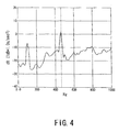
- Figs. 4 to 6 show relationships between the compressive force applied to the coil spring of the electric vacuum cleaner according to the first embodiment of the present invention and vibration transmitted from the electric blower to the electric blower case.
- Fig. 4 shows a relationship between vibration acceleration and frequency of the electric blower case when a compressive elastic support including four coil springs to which a compressive force of 8 N is applied,
- Fig. 5 shows a relationship between vibration acceleration and frequency of the electric blower case when a compressive elastic support including four coil springs to which a compressive force of 20 N is applied.
- Fig. 6 shows a relationship between vibration acceleration and frequency of the electric blower case when a compressive elastic support including eight coil springs to which a compressive force of 20 N is applied,
- the electric blower 21 has a mass of about 1 kg. When the electric blower 21 is operated, vibration having a peak substantially at 462 Hz is generated.
- Rigidity of the electric blower case 23 according to this embodiment is substantially two or three times the spring constant k2 of the coil spring 68.
- the compressive force F applied to the coil spring 68 of the elastic support 45 and the rigidity of the electric blower case 23 are adjusted as required, and the number of coil springs 68 used is selected, and thus the resonance frequency of the electric blower case 23 can be changed to effectively isolate the vibration transmitted from the electric blower 31 to the electric blower case 23.
- a spring coefficient of the coil spring 68 is substantially 5 N/mm, the number of coil springs 68 is four, and the initial compressive force applied to the coil spring 68 is substantially 20 N.
- the electric vacuum cleaner 1 compressively elastically support the electric blower 21 in the electric blower case 23 to isolate noise and vibration caused by the operation of the electric blower 21.
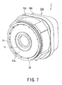
- Fig. 7 is a perspective view showing an electric blower case of the electric vacuum cleaner according to the second embodiment of the present invention.
- the electric blower case 23A of the electric vacuum cleaner 1A includes a suction side case member 25A and an exhaust side case member 26A.
- the electric blower case 23A is formed of synthetic resin such as ABS.
- the suction side case member 25A covers a centrifugal fan portion 21d and a part of a motor portion 21c of an electric blower 21, and the exhaust side case member 26A covers the other parts of the motor portion 21c.
- the suction side case member 25A is formed into a closed-end cylindrical shape with one side opened.
- the suction side case member 25A includes a disk-shaped suction port side bottom wall 47A.
- a seal member 75 is provided at the center of the suction port side bottom wall 47A.
- a front cover support member 29 is provided on a ring-shaped step 76 formed in a peripheral edge of the suction port side bottom wall 47A.
- the exhaust side case member 26A is formed into a tubular shape having a substantially square section perpendicularly to an axial direction.
- Fig. 8 is a partially fragmentary perspective view of the electric blower case and the electric blower of the electric vacuum cleaner according to the second embodiment of the present invention.
- Fig. 8 only a casing of the electric blower 21 is shown.
- the electric blower case 23A of the electric vacuum cleaner 1A houses the electric blower 2 1 compressively elastically supported by an elastic support 45A.
- the elastic support 45A elastically supports the electric blower 21 axially and radially.
- the suction side case member 25A is formed into a closed-end cylindrical shape with one side opened.
- a suction port side bottom wall 47A that is a bottom surface of the suction side case member 25A has a seal member mounting hole 77.
- the seal member 75 is fitted in the seal member mounting hole 77.
- a suction side case flange 79 is formed on an opening side end of the suction side case member 25A.
- a suction side case joining portion 80 is provided near an outer peripheral edge of the suction side case flange 79. The suction side case joining portion 80 protrudes toward an opening in the suction side case member 25A.
- the seal member 75 is constituted by two truncated conical hollow bodies with small diameter sides thereof jointed each other. A small diameter portion 75a that is an abutment portion of the two truncated conical hollow bodies is fitted in the seal member mounting hole 77.
- One truncated conical hollow body 75b placed inside the electric blower case 23A has a large diameter opening 75c with a flange. The large diameter opening 75c abuts on a peripheral edge of the suction port 21a in the electric blower 21.
- the other truncated conical hollow body 75d placed outside the electric blower case 23A has a large diameter opening 75e with a flange. The large diameter opening 75e fluidically communicates with a connection air path 33 in a vacuum cleaner body 2.
- a vent path 75f formed in the small diameter portion 75a of the seal member 75 provides fluidic communication between the connection air path 33 in the vacuum cleaner body 2 and the suction port 21a in the electric bower 21.
- the seal member 75 partitions an inside of the electric blower case 23 into a side of the suction port 21a and a side of the exhaust port 21b in the electric blower 21.
- the exhaust side case member 26A is formed into a closed-end rectangular cylindrical shape with one side opened and having a substantially square section perpendicularly to an axis.
- An exhaust port side bottom wall 54A that is a bottom surface of the exhaust side case member 26A includes a bearing insertion protrusion 82 that supports a bearing housing 21e of the electric blower 21.
- the bearing housing 21e houses a bearing (not shown) that rotatably journals a rotor (not shown) of a motor (not shown).
- the bearing insertion protrusion 82 supports the bearing housing 21e via a motor support member 83.
- a rear cover support member 30 is provided on an outer periphery of the bearing insertion protrusion 82.
- a side wall of the exhaust side case member 26A has a case exhaust port 55A spaced from the exhaust port 21b in the electric blower 21.
- a groove-shaped exhaust side case joining portion 84 is formed at an opening side end of the exhaust side case member 26A.
- the suction side case member 25A and the exhaust side case member 26A are integrally fitted with a part of the suction side case joining portion 80 fitted in the exhaust side case joining portion 84.
- the exhaust side case member 26A and the suction side case member 25 are joined by a fastening member (not shown) such as a screw.
- a barrel of the exhaust side case member 26A includes a large rectangular cylinder 86 and a small rectangular cylinder 87.
- the large rectangular cylinder 86 forms a barrel on the opening end side of the exhaust side case member 26A, A length of a side of the large rectangular cylinder 86 is equal to a diameter of a cylindrical barrel of the suction side case member 25A.
- the small rectangular cylinder 87 is formed continuously from the large rectangular cylinder 86,
- a square frame-shaped stepped surface 61A facing an opening in the exhaust side case member 26A is formed between the large rectangular cylinder 86 and the small rectangular cylinder 87.
- the elastic support 45A is held between the stepped surface 61A and the suction side case flange 79.
- radial displacement of the elastic support 45A is constrained by the suction side case joining portion 80 and the large rectangular cylinder 86, while axial displacement of the elastic support 45A is constrained by the stepped surface 61A and the suction side case flange 79.
- a semicircular mounting recess 27a is formed in a mounting portion 27 of the vacuum cleaner body 2, and a semicircular mounting recess 28a is formed in a mounting portion 28.
- the electric blower case 23A is held in the vacuum cleaner body 2 with a front cover support member 29 fitted in the mounting recess 27a in the mounting portion 27 and a rear cover support member 30 fitted in the mounting recess 28a in the mounting portion 28,
- Fig. 9 is a perspective view showing the electric blower case and the electric blower of the electric vacuum cleaner according to the second embodiment of the present invention.
- the electric blower case 23A is shown with the exhaust side case member 26A removed.
- Fig. 10 is a perspective view of an outer peripheral ring of the electric vacuum cleaner according to the second embodiment of the present invention.
- the suction side case joining portion 80 of the suction side case member 25A is formed into a square frame shape with each corner chamfered in an arcuate or linear shape, and the elastic support 45A is fitted therein.
- the elastic support 45A is a vibration isolating support portion that isolates vibration caused by an operation of the electric blower 21.
- the elastic support 45A includes an inner peripheral ring 66A, an outer peripheral ring 67A, and a coil spring 68A.
- the inner peripheral ring 66A is provided on an outer periphery of the motor portion 21c near the center of gravity of the electric blower 21.
- a protrusion 70 to which the coil spring 68A is locked protrudes radially outward on an outer surface of the inner peripheral ring 66A.
- a flange 71 is formed on the inner peripheral ring 66A. The inner peripheral ring 66A is secured to the outer periphery of the motor portion 21c with the flange 71 fastened by a fastening member 72 such as a screw.
- the outer peripheral ring 67A is provided along an inner periphery of the suction side case joining portion 80, and held between the stepped surface 61 of the exhaust side case member 26A and the suction side case flange 79 on the suction side case member 25A.
- the outer peripheral ring 67A is formed of a metal member, for example, an iron sheet strip as a heat resistant member, and has higher annular rigidity than that of a barrel of the electric blower case 23A.
- the outer peripheral ring 67A includes an annular reinforcing ring 89, and a spring joining recess 90 provided from an arc of the reinforcing ring 89 toward a corner of the suction side case joining portion 80.
- the reinforcing ring 89 has a portion abutting on an inner peripheral surface of the suction side case joining portion 80.
- An engagement recess 91 that holds the spring joining recess 90 is formed in the suction side case joining portion 80 of the suction side case member 25A.
- the spring joining recess 90 in the outer peripheral ring 67A and the protrusion 70 on the inner peripheral ring 66A are spaced and face each other.
- a compressive force F is applied to the coil spring 68A, and the coil spring 68A is provided between the protrusion 70 on the inner peripheral ring 66A and the spring joining recess 90 in the outer peripheral ring 67A.
- One end of the coil spring 68A is fitted in the protrusion 70 on the inner peripheral ring 66A, while the other end thereof is fitted in the spring joining recess 90 in the outer peripheral ring 67A,
- a required number equal to or larger than three of, for example, four coil springs 68A are placed between the inner peripheral ring 66A and the outer peripheral ring 67A at radially regularly spaced intervals, Specifically, the coil spring 68A to which the compressive force F is applied radially to the electric blower 21 elastically supports the electric blower 21 in the electric blower case 23A.
- a different type of spring or elastic body such as a leaf spring or a torsion bar that can apply a compressive force F between the inner peripheral ring 66A and the outer peripheral ring 67A may be used to constitute the elastic support 45A.
- the elastic support 45A applies the compressive force F to the coil spring 68A to support the electric blower 21.
- a spaced distance between the inner peripheral ring 66A and the outer peripheral ring 67A where the coil spring 68 is provided can be shorter than a spaced distance required for applying a tensile force to a coil spring having the same diameter. This minimize a spaced distance between the electric blower case 23A and the electric blower 21, and reduce the outer diameter of the electric blower case 23A, and thus reduce the size and weight of the electric blower case 23A.
- the electric blower case 23A is made of synthetic resin to reduce the weight of the vacuum cleaner body 2- This may cause the electric blower case 23A to be heated by heat generation or the like of the motor of the electric blower 21.
- the elastic support 45A includes the outer peripheral ring 67A having higher rigidity than the electric blower case 23A, and thus the compressive force F of the coil spring 68 can prevent deformation of the electric blower case 23A, and maintain a holding position of the electric blower 21.
- the electric vacuum cleaner 1A according to this embodiment prevents a reduction in performance due to changes in holding position of the electric blower 21.
- Fig- 11 is a perspective view showing another example of a suction side case member of the electric vacuum cleaner according to the second embodiment of the present invention.
- Fig. 12 is a back view showing another example of the suction side case member of the electric vacuum cleaner according to the second embodiment of the present invention.
- a suction side case member 25B has an engagement recess 91A and a female screw 92 protruding radially outward from a substantially cylindrical barrel.
- the engagement recess 91A holds the spring joining recess 90 in the outer peripheral ring 67A.
- a fastening member (not shown) that fastens the suction side case member 25B and the exhaust side case member 26A is threaded into the female screw 92.
- the suction side case member 25B holds the substantially entire outer periphery of the annular reinforcing ring 89 of the outer peripheral ring 67A.
- a reaction of the compressive force F of the coil spring 68A is equally divided substantially over the entire periphery of the suction side case member 25B.
- Fig. 13 is a perspective view showing another example of an exhaust side case member of the electric vacuum cleaner according to the second embodiment of the present invention.
- the outer peripheral ring 67A of the elastic support 45A may be provided in an exhaust side case member 26B.
- the exhaust side case member 26B has an engagement recess 91B that holds the spring joining recess 90 in the outer peripheral ring 67A.
- the elastic support 45A may be held by the suction side case member 25A or the exhaust side case member 26B, and the case member that holds the elastic support 45A may be selected as appropriate depending on assembly properties.
- Fig. 14 is a perspective view showing a further example of an exhaust side case member of the electric vacuum cleaner according to the second embodiment of the present invention.
- Fig. 15 is a perspective view showing another example of an outer peripheral ring of the electric vacuum cleaner according to the second embodiment of the present invention.
- an outer peripheral ring 67B of an elastic support 45B includes a screw mounting portion 94 (fastening portion) on the reinforcing ring 89.
- the screw mounting portion 94 of the outer peripheral ring 67B is secured to an exhaust side case member 26C by a fastening member such as a screw.
- the compressive force F of the coil spring 68A causes a force inward of the electric blower case 23A to be applied to the reinforcing ring 89 of the outer peripheral ring 67B,
- the reinforcing ring 89 is integrally secured to the exhaust side case member 26C by the screw mounting portion 94, thereby preventing deformation caused by the compressive force F of the coil spring 68A or the vibration of the electric blower 21.
- Fig. 16 is a back view showing another example of the outer peripheral ring of the electric vacuum cleaner according to the second embodiment of the present invention.
- an outer peripheral ring 67C is made of an aluminum alloy by die casting.
- the outer peripheral ring 67C has a substantially square frame-shaped outer periphery and a circular inner periphery.
- Three coil springs 68A are placed at regularly spaced intervals of about 120°.
- the electric blower case 23A is made of synthetic resin to reduce the weight of the vacuum cleaner body 2. This may cause the electric blower case 23A to be heated by heat generation or the like of the motor of the electric blower 21.
- the elastic support 45A includes the outer peripheral ring 67C having higher rigidity than the electric blower case 23A, and thus the compressive force F of the coil spring 68 can prevent deformation of the electric blower case 23A, and maintain a holding position of the electric blower 21.
- the electric vacuum cleaner 1A prevents a reduction in performance due to changes in holding position of the electric blower 21.
- the electric vacuum cleaner 1A can compressively elastically support the electric blower 21 in the electric blower case 23A to isolate noise and vibration due to the operation of the electric blower 21.
- the electric vacuum cleaner 1 or 1A according to the present invention is not limited to a canister electric vacuum cleaner 1 or 1A, but may be an upright, stick, or hand-held electric vacuum cleaner 1 or 1A.
Abstract
Description
- The present invention relates to an electric vacuum cleaner including an electric blower case housing an electric blower, and a vibration isolating support portion that isolates vibration generated by the electric blower.
- A general electric vacuum cleaner sucks dust accumulated on a surface to be cleaned such as a floor together with air from a suction port provided at a front end of a dust collection hose communicating with a vacuum cleaner body using negative pressure generated by an operation of an electric blower housed in the vacuum cleaner body, catches the dust with a dust removal unit or a filter of high speed separation type provided in the vacuum cleaner body, and cleans the surface to be cleaned.
- For the electric blower used in the electric vacuum cleaner, unnecessary pressure variations are always caused in air as a working fluid, and the pressure variations propagate to a periphery and often generate noise. For example, periodical pressure variations occur in a space with motion of a rotor blade of a fan, and the pressure variations propagate as noise. In the electric blower, fluid vibration such as surging and mechanical vibration due to imbalance of a rotor occur- A vibration isolating support portion that isolates the noise and vibration of the electric blower desirably supports a position with small amplitude sufficiently softly. The vibration isolating support portion also needs to radially support weight of the electric blower and axially support a suction force generated by the operation of the electric blower.
- Thus,
Patent Document 1 describes an electric vacuum cleaner that uses, a spring member provided between near the center of gravity of an electric blower and a vacuum cleaner body, the spring member provided via an outer peripheral ring provided on the vacuum cleaner body, a shock absorbing rear elastic body provided between a motor and the vacuum cleaner body with a gap, and a shock absorbing front elastic body provided between an outer periphery of a fan and the body with a gap, and elastically supports the electric blower in the vacuum cleaner body, - Patent Document 1: Japanese Patent Laid-Open No.
5-84194 - The electric blower in the conventional electric vacuum cleaner described in
Patent Document 1 is elastically supported in tension in the vacuum cleaner body by a coil spring to which a tensile force is applied, a force applied radially to the electric blower is softly supported, while a force applied axially of the electric blower is firmly supported with increasing axial displacement, thereby preventing vibration caused by an operation of the electric blower from transmitting to the vacuum cleaner body, - However, to apply the tensile force to the coil spring, the coil spring needs to be stretched to be longer than a free length. Then, when a sufficient space cannot be obtained between an inner surface of an electric blower housing chamber and the electric blower, the coil spring cannot be stretched to elastically support the electric blower in tension,
- Also, there is a case where, for example, an electric blower is housed in an electric blower case, and the electric blower case is housed in an electric vacuum cleaner body to isolate noise and vibration due to an operation of the electric blower. When a coil spring is stretched to elastically support the electric blower in tension in the electric blower case, it is difficult to both ensure a spaced distance between the electric blower and the electric blower case required for stretching the coil spring and reduce size of the electric blower case.
- To increase convenience of an electric vacuum cleaner, a vacuum cleaner body and an electric blower case need to be light in weight. However, an electric blower case formed of resin such as ABS to be thin and light in weight does not have sufficient rigidity, and it is difficult to elastically support an electric blower in tension in the electric blower case with a coil spring.
- Further, providing a viscoelastic body such as rubber or urethane around an electric blower to isolate vibration and noise is suitable for reducing a resonance peak component of the electric blower, but a sufficient advantage cannot be obtained in a frequency range other than the resonance peak component.
- The present invention proposes an electric vacuum cleaner that can compressively elastically support an electric blower in an electric blower case to isolate noise and vibration caused by an operation of the electric blower.
- To achieve the above-described object, the present invention provides an electric vacuum cleaner including: an electric blower that sucks air containing dust into the electric vacuum cleaner; an electric blower case that houses the electric blower; and a vibration isolating support portion that is formed in the electric blower case, and elastically supports the electric blower by a compressive force applied radially to the electric blower.
-
-
Fig. 1 is a perspective view showing an appearance of an electric vacuum cleaner according to a first embodiment of the present invention; -
Fig. 2 is a vertical sectional view showing a vacuum cleaner body of the electric vacuum cleaner according to the first embodiment of the present invention; -
Fig. 3 is a partially fragmentary perspective view of an electric blower case and an electric blower of the electric vacuum cleaner according to the first embodiment of the present invention; -
Fig. 4 shows a relationship between a compressive force applied to a coil spring of the electric vacuum cleaner according to the first embodiment of the present invention and vibration transmitted from the electric blower to the electric blower case; -
Fig. 5 shows a relationship between a compressive force applied to the coil spring of the electric vacuum cleaner according to the first embodiment of the present invention and vibration transmitted from the electric blower to the electric blower case; -
Fig. 6 shows a relationship between a compressive force applied to the coil spring of the electric vacuum cleaner according to the first embodiment of the present invention and vibration transmitted from the electric blower to the electric blower case; -
Fig. 7 is a perspective view showing an electric blower case of the electric vacuum cleaner according to a second embodiment of the present invention; -
Fig. 8 is a partially fragmentary perspective view of the electric blower case and an electric blower of the electric vacuum cleaner according to the second embodiment of the present invention; -
Fig. 9 is a perspective view showing the electric blower case and the electric blower of the electric vacuum cleaner according to the second embodiment of the present invention; -
Fig. 10 is a perspective view of an outer peripheral ring of the electric vacuum cleaner according to the second embodiment of the present invention; -
Fig. 11 is a perspective view showing another example of a suction side ease member of the electric vacuum cleaner according to the second embodiment of the present invention; -
Fig. 12 is a back view showing another example of the suction side case member of the electric vacuum cleaner according to the second embodiment of the present invention; -
Fig. 13 is a perspective view showing another example of an exhaust side case member of the electric vacuum cleaner according to the second embodiment of the present invention; -
Fig. 14 is a perspective view showing a further example of an exhaust side case member of the electric vacuum cleaner according to the second embodiment of the present invention; -
Fig. 15 is a perspective view showing another example of an outer peripheral ring of the electric vacuum cleaner according to the second embodiment of the present invention; and -
Fig. 16 is a back view showing another example of the outer peripheral ring of the electric vacuum cleaner according to the second embodiment of the present invention. - Embodiments of an electric vacuum cleaner according to the present invention will be described below with reference to the drawing.
- A first embodiment of the electric vacuum cleaner according to the present invention will be described with reference to
Figs, 1 to 6 . -
Fig. 1 is a perspective view showing an appearance of the electric vacuum cleaner according to the first embodiment of the present invention. - As shown in
Fig. 1 , theelectric vacuum cleaner 1 according to this embodiment includes a vacuum cleaner body 2, a dust collection hose 3, a hand operation pipe 4, a grip portion 5, anoperation unit 6, an extension wand 7, and a suction port 8. - The vacuum cleaner body 2 has a
connection port 2a to which one end of the dust collection hose 3 is removably connected. The vacuum cleaner body 2 also includes apower cord 11. Apower plug 12 is formed at a free end of thepower cord 11. - The dust collection hose 3 is flexible and formed into a bendable elongated substantially cylindrical shape. One end of the dust collection hose 3 is removably connected to the
connection port 2a to communicate with the inside of the vacuum cleaner body 2. - One end of the hand operation pipe 4 is provided at the other end of the dust collection hose 3, and fluidically communicates with the inside of the vacuum cleaner body 2 via the dust collection hose 3
- The grip portion 5 is gripped by a user of the
electric vacuum cleaner 1 for an operation of theelectric vacuum cleaner 1. The grip portion 5 is provided to protrude in a curved manner from the other end of the hand operation pipe 4 toward one end of the hand operation pipe 4 at which the dust collection hose 3 is provided. - The
operation unit 6 is provided on the grip portion 5. When the user of theelectric vacuum cleaner 1 operates theoperation unit 6, theelectric vacuum cleaner 1 is set to a plurality of drive modes. Theoperation unit 6 includes anoff switch 6a for stopping the operation of theelectric vacuum cleaner 1, and an onswitch 6b for starting the operation of theelectric vacuum cleaner 1. - The extension wand 7 is formed into a stretchable elongated substantially cylindrical shape. One end of the extension wand 7 is removably connected to the other end of the hand operation pipe 4, and fluidically communicates with the inside of the vacuum cleaner body 2 via the hand operation pipe 4 and the dust collection hose 3.
- The suction port 8 is removably connected to one end of the extension wand 7, and fluidically communicates with the inside of the vacuum cleaner body 2 via the extension wand 7, the hand operation pipe 4, and the dust collection hose 3.
-
Fig. 2 is a vertical sectional view showing the vacuum cleaner body of the electric vacuum cleaner according to the first embodiment of the present invention. - As shown in
Fig. 2 , the vacuum cleaner body 2 of theelectric vacuum cleaner 1 includes abody case 15, a dust separation andcollection unit 16 removably mounted in thebody case 15, and alid case 17 openably provided in thebody case 15. - A
dust collection chamber 19 to which the dust separation andcollection unit 16 is removably mounted is formed on a front side of thebody case 15. Anupper opening 20 in thedust collection chamber 19 is sealed by thelid case 17. - An electric
blower housing chamber 22 housing anelectric blower 21 is formed on a rear side of thebody case 15. Anelectric blower case 23 covers theelectric blower 21 and is housed in the electricblower housing chamber 22, Theelectric blower case 23 includes a suctionside case member 25 and an exhaustside case member 26. Theelectric blower case 23 is held by amounting portion 27 provided on a front side of the electricblower housing chamber 22 and amounting portion 28 provided on a rear side of the electricblower housing chamber 22. A frontcover support member 29 is provided between theelectric blower case 23 and the mountingportion 27, and a rearcover support member 30 is provided between theelectric blower case 23 and the mountingportion 28. The frontcover support member 29 and the rearcover support member 30 are elastic bodies such as rubber or silicone. - A cylindrical
connection air path 33 having a front surface opening 32 is formed on the front side of the electricblower housing chamber 22. The front surface opening 32 opens into thedust collection chamber 19. Aseal ring 34 is mounted to thefront surface opening 32. Theseal ring 34 is packing between the dust separation andcollection unit 16 and theconnection air path 33. Alattice member 35 is provided in theconnection air path 33. Aconnection opening 37 is formed in arear wall 36 of theconnection air path 33. Theconnection opening 37 fluidically communicates with theelectric blower 21 covered by theelectric blower case 23. - The dust separation and
collection unit 16 includes adust separation unit 39 that separates coarse dust from dust-containing air by an inertial separation method, a dust collection unit 40 -that collects the coarse dust separated by thedust separation unit 39, anet filter 41 through which the dust-containing air from which the coarse dust is separated by thedust separation unit 39 passes, and apleated filter 42 that separates and collects fine dust from the dust-containing air, Thepleated filter 42 is housed in afilter housing case 43 integrally formed with thedust separation unit 39. - When the user of the
electric vacuum cleaner 1 operates the onswitch 6b, theelectric vacuum cleaner 1 starts an operation. When the operation of theelectric vacuum cleaner 1 is started, theelectric blower 21 is operated and negative pressure is applied to an inside of the vacuum cleaner body 2. The negative pressure is applied from theconnection port 2a via the dust collection hose 3, the hand operation pipe 4, and the extension wand 7 to the suction port 8, Then, theelectric vacuum cleaner 1 sucks dust accumulated on a surface to be cleaned such as a floor together with air from the suction port 8 and cleans the surface to be cleaned. The dust-containing air sucked by the suction port 8 is separated into air and dust by the dust separation andcollection unit 16 housed in the vacuum cleaner body 2. The separated dust is collected by thedust collection unit 40 and thepleated filter 42. Meanwhile, the separated air is sucked by theelectric blower 21 and discharged from the vacuum cleaner body 2. -
Fig. 3 is a partially fragmentary perspective view of the electric blower case and the electric blower of the electric vacuum cleaner according to the first embodiment of the present invention. - In
Fig. 3 , only a casing of theelectric blower 21 is shown. - As shown in
Fig. 3 , theelectric blower case 23 of theelectric vacuum cleaner 1 houses theelectric blower 21 compressively elastically supported by anelastic support 45. Theelastic support 45 elastically supports theelectric blower 21 axially and radially. - The
electric blower 21 includes a motor (not shown), a centrifugal fan (not shown) rotated by the motor, and a diffuser (not shown) provided on an outer periphery of the centrifugal fan Theelectric blower 21 has asuction port 21a through which air is sucked by negative pressure caused by an operation of the centrifugal fan, and anexhaust port 21 b through which the sucked air is exhausted. When the motor is operated, theelectric blower 21 rotates the centrifugal fan and sucks air through thesuction port 21a. The air sucked by theelectric blower 21 passes from the centrifugal fan through the diffuser and cools the motor. Theelectric blower 21 exhausts the air having cooled the motor through theexhaust port 21b. - The
electric blower case 23 is formed of synthetic resin such as ABS into a substantially closed-end cylindrical shape. Theelectric blower case 23 includes a suctionside case member 25 and an exhaustside case member 26. - The suction
side case member 25 is formed into a closed-end cylindrical shape with one side opened. A suction port sidebottom wall 47 that is a bottom surface of the suctionside case member 25 has acase suction port 48. Thecase suction port 48 fluidically communicates with theconnection air path 33 in the vacuum cleaner body 2 and fluidically communicates with thesuction port 21a in theelectric blower 21. Asuction port rib 49 is formed in thecase suction port 48 continuously from the suction port sidebottom wall 47. Thesuction port rib 49 abuts on aseal 50 provided in thesuction port 21a in theelectric blower 21. Theseal 50 is formed of an elastic body such as rubber into an annular shape. Theseal 50 has ahole 50a that provides communication between thecase suction port 48 and thesuction port 21a. Theseal 50 partitions an inside of theelectric blower case 23 into a side of thesuction port 21a and a side of theexhaust port 21b in theelectric blower 21. A suction sidecase joining flange 52 is formed on an opening side end of the suctionside case member 25. - The exhaust
side case member 26 is formed into a closed-end cylindrical shape with one side opened. An exhaust port side bottom wall 54 that is a bottom surface of the exhaustside case member 26 has acase exhaust port 55. Thecase exhaust port 55 is spaced apart from theexhaust port 21b in theelectric blower 21, and fluidically communicates with theexhaust port 21b. An exhaust sidecase joining flange 57 is formed at an opening side end of the exhaustside case member 26. The suctionside case member 25 and the exhaustside case member 26 are integrally joined by a fastening member (not shown) such as a screw that secures the suction sidecase joining flange 52 and the exhaust sidecase joining flange 57. - A cylindrical barrel of the exhaust
side case member 26 includes alarge diameter cylinder 58 and asmall diameter cylinder 59. Thelarge diameter cylinder 58 is formed continuously from the exhaust sidecase joining flange 57. A diameter of thelarge diameter cylinder 58 is larger than a diameter of a cylindrical barrel of the suctionside case member 25. Thesmall diameter cylinder 59 is formed continuously from thelarge diameter cylinder 58. A diameter of thesmall diameter cylinder 59 is substantially equal to the diameter of the cylindrical barrel of the suctionside case member 25. - An annular stepped
surface 61 facing the opening in the exhaustside case member 26 is formed between thelarge diameter cylinder 58 and thesmall diameter cylinder 59. Meanwhile, an inner diameter of the exhaust sidecase joining flange 57 is formed to be larger than an inner diameter of the suction sidecase joining flange 52. The difference in inner diameter forms an annular steppedsurface 62 on the suction sidecase joining flange 52 so as to face the steppedsurface 61 of the exhaustside case member 26. Acylindrical spacer 64 and theelastic support 45 are held between the stepped surfaces 61 and 62. Thus, radial displacement of theelastic support 45 is constrained by thelarge diameter cylinder 58 of the exhaustside case member 26, while axial displacement of theelastic support 45 is constrained by the stepped surfaces 61 and 62. - The
elastic support 45 is a vibration isolating support portion that isolates vibration caused by the operation of theelectric blower 21. Theelastic support 45 includes an innerperipheral ring 66, an outerperipheral ring 67, and acoil spring 68. - The inner
peripheral ring 66 is provided on an outer periphery of amotor portion 21c near the center of gravity of theelectric blower 21. Aprotrusion 70 to which thecoil spring 68 is locked protrudes radially outward on an outer surface of the innerperipheral ring 66. - The outer
peripheral ring 67 is held between the steppedsurface 61 of the exhaustside case member 26 and the steppedsurface 62 of the suction sidecase joining flange 52 via thecylindrical spacer 64, and provided on an inner periphery of the exhaustside case member 26. Aprotrusion 73 to which thecoil spring 68 is locked protrudes radially inward on an inner surface of the outerperipheral ring 67. Theprotrusion 73 on the outerperipheral ring 67 and theprotrusion 70 on the innerperipheral ring 66 are spaced and face each other. - The
coil spring 68 is an elastic support member to which a compressive force F is applied, and that is provided between theprotrusion 70 on the innerperipheral ring 66 and theprotrusion 73 on the outerperipheral ring 67. One end of thecoil spring 68 is fitted on theprotrusion 70 on the innerperipheral ring 66, and the other end thereof is fitted on theprotrusion 73 on the outerperipheral ring 67. A required number equal to or larger than three of, for example, fourcoil springs 68 are placed between the innerperipheral ring 66 and the outerperipheral ring 67 at radially regularly spaced intervals. Specifically, thecoil spring 68 to which the compressive force F is applied radially to theelectric blower 21 elastically supports theelectric blower 21 in theelectric blower case 23. Instead of thecoil spring 68, a different type of spring or elastic body such as a leaf spring or a torsion bar that can apply a compressive force F between the innerperipheral ring 66 and the outerperipheral ring 67 may be used to constitute theelastic support 45. - The
elastic support 45 applies the compressive force F to thecoil spring 68 to support theelectric blower 21. Thus, a spaced distance between the innerperipheral ring 66 and the outerperipheral ring 67 where thecoil spring 68 is provided may be shorter than a spaced distance required for applying a tensile force to a coil spring having the same diameter. This minimize a spaced distance between theelectric blower case 23 and theelectric blower 21, and reduce the outer diameter of theelectric blower case 23, and thus reduce size and weight of theelectric blower case 23. -
Figs. 4 to 6 show relationships between the compressive force applied to the coil spring of the electric vacuum cleaner according to the first embodiment of the present invention and vibration transmitted from the electric blower to the electric blower case. - In
Figs. 4 to 6 , the ordinate represents vibration acceleration of theelectric blower case 23 when 0 dB = 1.0 m/sec2. -
Fig. 4 shows a relationship between vibration acceleration and frequency of the electric blower case when a compressive elastic support including four coil springs to which a compressive force of 8 N is applied, -
Fig. 5 shows a relationship between vibration acceleration and frequency of the electric blower case when a compressive elastic support including four coil springs to which a compressive force of 20 N is applied. -
Fig. 6 shows a relationship between vibration acceleration and frequency of the electric blower case when a compressive elastic support including eight coil springs to which a compressive force of 20 N is applied, - The relationship between vibration acceleration and frequency of the
electric blower case 23 shown inFig. 4 is an observation result obtained using acoil spring 68 with a spring constant of k1 = 2 N/mm, and the relationships between vibration acceleration and frequency of theelectric blower case 23 shown inFigs. 5 and6 are observation results obtained using acoil spring 68 with a spring constant of k2 = 5 N/mm. Theelectric blower 21 has a mass of about 1 kg. When theelectric blower 21 is operated, vibration having a peak substantially at 462 Hz is generated. Rigidity of theelectric blower case 23 according to this embodiment is substantially two or three times the spring constant k2 of thecoil spring 68. - As shown in
Fig. 4 , vibration transmitted from theelectric blower 21 via thecoil spring 68 to which an initial compressive force F0A = 8 N is applied to theelectric blower case 23 has an acceleration peak of 1.71 dB = 1.22 m/sec2 at 462 Hz. - As shown in
Fig. 5 , vibration transmitted from theelectric blower 21 via thecoil spring 68 to which an initial compressive force F0B = 20 N is applied to theelectric blower case 23 has an acceleration peak of -3.15 dB = 0.69 m/sec2 at 462 Hz. - As shown in
Fig. 6 , vibration transmitted from theelectric blower 21 via thecoil spring 68 to which an initial compressive force FOB = 20 N is applied to theelectric blower case 23 has an acceleration peak of 16.4 dB = 6.58 m/sec2 at 488 Hz. - It is clear from a comparison between
Figs. 4 and5 that a higher initial compressive force applied to thecoil spring 68 can more reliably isolate vibration transmitted from theelectric blower 21 via theelastic support 45 to theelectric blower case 23. The advantage of vibration isolation is provided in a wide frequency band substantially from 50 Hz to 800 Hz, and is particularly noticeably at the acceleration peak of theelectric blower 21 observed at 462 Hz. - It is clear from a comparison between
Figs. 5 and6 that the vibration transmitted from theelectric blower 21 via theelastic support 45 to theelectric blower case 23 cannot be effectively isolated even with the same initial compressive force applied to thecoil spring 68 of theelastic support 45 when the number ofcoil springs 68 used is changed. - It is supposed that a main factor for the observation result is that resonance frequency of the
electric blower case 23 is changed because theelectric blower case 23 is expanded radially outward and deformed by the compressive force F applied to thecoil spring 68, and because initial stress is applied to theelectric blower case 23 to change apparent rigidity of theelectric blower case 23, which is stress hardening, Thus, the compressive force F applied to thecoil spring 68 can be adjusted to change the resonance frequency of theelectric blower case 23 to isolate the vibration transmitted from theelectric bower 21 to theelectric blower case 23. - Specifically, when a sufficient thickness of the
electric blower case 23 cannot be ensured because of a reduction in size and weight thereof, the compressive force F applied to thecoil spring 68 of theelastic support 45 and the rigidity of theelectric blower case 23 are adjusted as required, and the number ofcoil springs 68 used is selected, and thus the resonance frequency of theelectric blower case 23 can be changed to effectively isolate the vibration transmitted from the electric blower 31 to theelectric blower case 23. - In the
electric vacuum cleaner 1 according to this embodiment, it is preferable that a spring coefficient of thecoil spring 68 is substantially 5 N/mm, the number of coil springs 68 is four, and the initial compressive force applied to thecoil spring 68 is substantially 20 N. - The
electric vacuum cleaner 1 according to this embodiment compressively elastically support theelectric blower 21 in theelectric blower case 23 to isolate noise and vibration caused by the operation of theelectric blower 21. - A second embodiment of the electric vacuum cleaner according to the present invention will be described with reference to
Figs. 7 to 16 . - In this embodiment, the same components as in the first embodiment are denoted by the same reference numerals and overlapping descriptions will be omitted.
-
Fig. 7 is a perspective view showing an electric blower case of the electric vacuum cleaner according to the second embodiment of the present invention. - As shown in
Fig. 7 , theelectric blower case 23A of the electric vacuum cleaner 1A includes a suctionside case member 25A and an exhaustside case member 26A. Theelectric blower case 23A is formed of synthetic resin such as ABS. - The suction
side case member 25A covers a centrifugal fan portion 21d and a part of amotor portion 21c of anelectric blower 21, and the exhaustside case member 26A covers the other parts of themotor portion 21c. - The suction
side case member 25A is formed into a closed-end cylindrical shape with one side opened. The suctionside case member 25A includes a disk-shaped suction port sidebottom wall 47A. Aseal member 75 is provided at the center of the suction port sidebottom wall 47A. A frontcover support member 29 is provided on a ring-shapedstep 76 formed in a peripheral edge of the suction port sidebottom wall 47A. - The exhaust
side case member 26A is formed into a tubular shape having a substantially square section perpendicularly to an axial direction. -
Fig. 8 is a partially fragmentary perspective view of the electric blower case and the electric blower of the electric vacuum cleaner according to the second embodiment of the present invention. - In
Fig. 8 , only a casing of theelectric blower 21 is shown. - As shown in
Fig. 8 , theelectric blower case 23A of the electric vacuum cleaner 1A houses the electric blower 2 1 compressively elastically supported by anelastic support 45A. Theelastic support 45A elastically supports theelectric blower 21 axially and radially. - The suction
side case member 25A is formed into a closed-end cylindrical shape with one side opened. A suction port sidebottom wall 47A that is a bottom surface of the suctionside case member 25A has a sealmember mounting hole 77. Theseal member 75 is fitted in the sealmember mounting hole 77. A suctionside case flange 79 is formed on an opening side end of the suctionside case member 25A. A suction sidecase joining portion 80 is provided near an outer peripheral edge of the suctionside case flange 79. The suction sidecase joining portion 80 protrudes toward an opening in the suctionside case member 25A. - The
seal member 75 is constituted by two truncated conical hollow bodies with small diameter sides thereof jointed each other. Asmall diameter portion 75a that is an abutment portion of the two truncated conical hollow bodies is fitted in the sealmember mounting hole 77. One truncated conicalhollow body 75b placed inside theelectric blower case 23A has alarge diameter opening 75c with a flange. Thelarge diameter opening 75c abuts on a peripheral edge of thesuction port 21a in theelectric blower 21. The other truncated conicalhollow body 75d placed outside theelectric blower case 23A has alarge diameter opening 75e with a flange. Thelarge diameter opening 75e fluidically communicates with aconnection air path 33 in a vacuum cleaner body 2. Avent path 75f formed in thesmall diameter portion 75a of theseal member 75 provides fluidic communication between theconnection air path 33 in the vacuum cleaner body 2 and thesuction port 21a in theelectric bower 21. Theseal member 75 partitions an inside of theelectric blower case 23 into a side of thesuction port 21a and a side of theexhaust port 21b in theelectric blower 21. - The exhaust
side case member 26A is formed into a closed-end rectangular cylindrical shape with one side opened and having a substantially square section perpendicularly to an axis. An exhaust port side bottom wall 54A that is a bottom surface of the exhaustside case member 26A includes a bearinginsertion protrusion 82 that supports a bearinghousing 21e of theelectric blower 21. The bearinghousing 21e houses a bearing (not shown) that rotatably journals a rotor (not shown) of a motor (not shown). The bearinginsertion protrusion 82 supports the bearinghousing 21e via amotor support member 83. A rearcover support member 30 is provided on an outer periphery of the bearinginsertion protrusion 82. A side wall of the exhaustside case member 26A has acase exhaust port 55A spaced from theexhaust port 21b in theelectric blower 21. A groove-shaped exhaust sidecase joining portion 84 is formed at an opening side end of the exhaustside case member 26A. The suctionside case member 25A and the exhaustside case member 26A are integrally fitted with a part of the suction sidecase joining portion 80 fitted in the exhaust sidecase joining portion 84. The exhaustside case member 26A and the suctionside case member 25 are joined by a fastening member (not shown) such as a screw. - A barrel of the exhaust
side case member 26A includes a largerectangular cylinder 86 and a smallrectangular cylinder 87. The largerectangular cylinder 86 forms a barrel on the opening end side of the exhaustside case member 26A, A length of a side of the largerectangular cylinder 86 is equal to a diameter of a cylindrical barrel of the suctionside case member 25A. The smallrectangular cylinder 87 is formed continuously from the largerectangular cylinder 86, - A square frame-shaped stepped
surface 61A facing an opening in the exhaustside case member 26A is formed between the largerectangular cylinder 86 and the smallrectangular cylinder 87. Theelastic support 45A is held between the steppedsurface 61A and the suctionside case flange 79. Thus, radial displacement of theelastic support 45A is constrained by the suction sidecase joining portion 80 and the largerectangular cylinder 86, while axial displacement of theelastic support 45A is constrained by the steppedsurface 61A and the suctionside case flange 79. - A
semicircular mounting recess 27a is formed in a mountingportion 27 of the vacuum cleaner body 2, and asemicircular mounting recess 28a is formed in a mountingportion 28. Theelectric blower case 23A is held in the vacuum cleaner body 2 with a frontcover support member 29 fitted in the mountingrecess 27a in the mountingportion 27 and a rearcover support member 30 fitted in the mountingrecess 28a in the mountingportion 28, -
Fig. 9 is a perspective view showing the electric blower case and the electric blower of the electric vacuum cleaner according to the second embodiment of the present invention. InFig. 9 , theelectric blower case 23A is shown with the exhaustside case member 26A removed. -
Fig. 10 is a perspective view of an outer peripheral ring of the electric vacuum cleaner according to the second embodiment of the present invention. - As shown in
Figs. 9 and10 , the suction sidecase joining portion 80 of the suctionside case member 25A is formed into a square frame shape with each corner chamfered in an arcuate or linear shape, and theelastic support 45A is fitted therein. - The
elastic support 45A is a vibration isolating support portion that isolates vibration caused by an operation of theelectric blower 21. Theelastic support 45A includes an innerperipheral ring 66A, an outerperipheral ring 67A, and acoil spring 68A. - The inner
peripheral ring 66A is provided on an outer periphery of themotor portion 21c near the center of gravity of theelectric blower 21. Aprotrusion 70 to which thecoil spring 68A is locked protrudes radially outward on an outer surface of the innerperipheral ring 66A. A flange 71 is formed on the innerperipheral ring 66A. The innerperipheral ring 66A is secured to the outer periphery of themotor portion 21c with the flange 71 fastened by afastening member 72 such as a screw. - The outer
peripheral ring 67A is provided along an inner periphery of the suction sidecase joining portion 80, and held between the steppedsurface 61 of the exhaustside case member 26A and the suction side case flange 79 on the suctionside case member 25A. The outerperipheral ring 67A is formed of a metal member, for example, an iron sheet strip as a heat resistant member, and has higher annular rigidity than that of a barrel of theelectric blower case 23A. - The outer
peripheral ring 67A includes an annular reinforcingring 89, and aspring joining recess 90 provided from an arc of the reinforcingring 89 toward a corner of the suction sidecase joining portion 80. The reinforcingring 89 has a portion abutting on an inner peripheral surface of the suction sidecase joining portion 80. Anengagement recess 91 that holds thespring joining recess 90 is formed in the suction sidecase joining portion 80 of the suctionside case member 25A. Thespring joining recess 90 in the outerperipheral ring 67A and theprotrusion 70 on the innerperipheral ring 66A are spaced and face each other. - A compressive force F is applied to the
coil spring 68A, and thecoil spring 68A is provided between theprotrusion 70 on the innerperipheral ring 66A and thespring joining recess 90 in the outerperipheral ring 67A. One end of thecoil spring 68A is fitted in theprotrusion 70 on the innerperipheral ring 66A, while the other end thereof is fitted in thespring joining recess 90 in the outerperipheral ring 67A, A required number equal to or larger than three of, for example, fourcoil springs 68A are placed between the innerperipheral ring 66A and the outerperipheral ring 67A at radially regularly spaced intervals, Specifically, thecoil spring 68A to which the compressive force F is applied radially to theelectric blower 21 elastically supports theelectric blower 21 in theelectric blower case 23A. Instead of thecoil spring 68A, a different type of spring or elastic body such as a leaf spring or a torsion bar that can apply a compressive force F between the innerperipheral ring 66A and the outerperipheral ring 67A may be used to constitute theelastic support 45A. - The
elastic support 45A applies the compressive force F to thecoil spring 68A to support theelectric blower 21. Thus, a spaced distance between the innerperipheral ring 66A and the outerperipheral ring 67A where thecoil spring 68 is provided can be shorter than a spaced distance required for applying a tensile force to a coil spring having the same diameter. This minimize a spaced distance between theelectric blower case 23A and theelectric blower 21, and reduce the outer diameter of theelectric blower case 23A, and thus reduce the size and weight of theelectric blower case 23A. - The
electric blower case 23A is made of synthetic resin to reduce the weight of the vacuum cleaner body 2- This may cause theelectric blower case 23A to be heated by heat generation or the like of the motor of theelectric blower 21. Thus, theelastic support 45A includes the outerperipheral ring 67A having higher rigidity than theelectric blower case 23A, and thus the compressive force F of thecoil spring 68 can prevent deformation of theelectric blower case 23A, and maintain a holding position of theelectric blower 21. Thus, the electric vacuum cleaner 1A according to this embodiment prevents a reduction in performance due to changes in holding position of theelectric blower 21. - Fig- 11 is a perspective view showing another example of a suction side case member of the electric vacuum cleaner according to the second embodiment of the present invention,
-
Fig. 12 is a back view showing another example of the suction side case member of the electric vacuum cleaner according to the second embodiment of the present invention. - As shown in
Figs. 11 and12 , a suctionside case member 25B has anengagement recess 91A and afemale screw 92 protruding radially outward from a substantially cylindrical barrel. Theengagement recess 91A holds thespring joining recess 90 in the outerperipheral ring 67A. A fastening member (not shown) that fastens the suctionside case member 25B and the exhaustside case member 26A is threaded into thefemale screw 92. - The suction
side case member 25B holds the substantially entire outer periphery of the annular reinforcingring 89 of the outerperipheral ring 67A. Thus, a reaction of the compressive force F of thecoil spring 68A is equally divided substantially over the entire periphery of the suctionside case member 25B. -
Fig. 13 is a perspective view showing another example of an exhaust side case member of the electric vacuum cleaner according to the second embodiment of the present invention. - As shown in
Fig. 13 , the outerperipheral ring 67A of theelastic support 45A may be provided in an exhaustside case member 26B. In this case, the exhaustside case member 26B has anengagement recess 91B that holds thespring joining recess 90 in the outerperipheral ring 67A. - Specifically, in the
electric blower case 23A, theelastic support 45A may be held by the suctionside case member 25A or the exhaustside case member 26B, and the case member that holds theelastic support 45A may be selected as appropriate depending on assembly properties. -
Fig. 14 is a perspective view showing a further example of an exhaust side case member of the electric vacuum cleaner according to the second embodiment of the present invention. -
Fig. 15 is a perspective view showing another example of an outer peripheral ring of the electric vacuum cleaner according to the second embodiment of the present invention. - As shown in
Figs. 14 and 15 , an outerperipheral ring 67B of an elastic support 45B includes a screw mounting portion 94 (fastening portion) on the reinforcingring 89. Thescrew mounting portion 94 of the outerperipheral ring 67B is secured to an exhaustside case member 26C by a fastening member such as a screw. - The compressive force F of the
coil spring 68A causes a force inward of theelectric blower case 23A to be applied to the reinforcingring 89 of the outerperipheral ring 67B, However, the reinforcingring 89 is integrally secured to the exhaustside case member 26C by thescrew mounting portion 94, thereby preventing deformation caused by the compressive force F of thecoil spring 68A or the vibration of theelectric blower 21. -
Fig. 16 is a back view showing another example of the outer peripheral ring of the electric vacuum cleaner according to the second embodiment of the present invention. - As shown in
Fig. 16 , an outerperipheral ring 67C is made of an aluminum alloy by die casting. The outerperipheral ring 67C has a substantially square frame-shaped outer periphery and a circular inner periphery. - Three
coil springs 68A are placed at regularly spaced intervals of about 120°. - The
electric blower case 23A is made of synthetic resin to reduce the weight of the vacuum cleaner body 2. This may cause theelectric blower case 23A to be heated by heat generation or the like of the motor of theelectric blower 21. Thus, theelastic support 45A includes the outerperipheral ring 67C having higher rigidity than theelectric blower case 23A, and thus the compressive force F of thecoil spring 68 can prevent deformation of theelectric blower case 23A, and maintain a holding position of theelectric blower 21. Thus, the electric vacuum cleaner 1A according to this embodiment prevents a reduction in performance due to changes in holding position of theelectric blower 21. - The electric vacuum cleaner 1A according to this embodiment can compressively elastically support the
electric blower 21 in theelectric blower case 23A to isolate noise and vibration due to the operation of theelectric blower 21. - The
electric vacuum cleaner 1 or 1A according to the present invention is not limited to a canisterelectric vacuum cleaner 1 or 1A, but may be an upright, stick, or hand-heldelectric vacuum cleaner 1 or 1A.
Claims (7)
- An electric vacuum cleaner comprising:a vacuum cleaner body;an electric blower case housed in the vacuum cleaner body;an electric blower that is housed in the electric blower case and sucks air; anda vibration isolating support portion that is provided in the electric blower case, and elastically supports the electric blower by a compressive force applied radially to the electric blower.
- The electric vacuum cleaner according to claim 1, wherein a resonance frequency of the electric blower case is changed by the compressive force applied from the vibration isolating support portion.
- The electric vacuum cleaner according to claim 1, wherein the vibration isolating support portion is provided on an inner periphery of the electric blower case, and includes an outer peripheral ring halving higher rigidity than the electric blower case.
- The electric vacuum cleaner according to claim 3, wherein the vibration isolating support portion includes an elastic support member to which a compressive force is applied, and
the outer peripheral ring includes a recess engaging one end of the elastic support member, and an annular portion abutting on an inner peripheral surface of the electric blower case. - The electric vacuum cleaner according to claim 4, wherein the electric blower case has an engagement recess holding the recess.
- The electric vacuum cleaner according to claim 5, wherein the annular portion of the outer peripheral ring includes a fastening portion secured to the electric blower case by a fastening member.
- The electric vacuum cleaner according to claim 4, wherein the electric blower case includes
a substantially cylindrical barrel in which the annular portion of the outer peripheral ring is fitted, and
an engagement recess in which the recess in the outer peripheral ring is fitted, and that protrudes radially outward from the barrel.
Applications Claiming Priority (3)
| Application Number | Priority Date | Filing Date | Title |
|---|---|---|---|
| JP2007302484A JP4620104B2 (en) | 2007-11-22 | 2007-11-22 | Electric vacuum cleaner |
| JP2007307750A JP4719206B2 (en) | 2007-11-28 | 2007-11-28 | Electric vacuum cleaner |
| PCT/JP2008/070897 WO2009066648A1 (en) | 2007-11-22 | 2008-11-18 | Electric cleaner |
Publications (2)
| Publication Number | Publication Date |
|---|---|
| EP2227998A1 true EP2227998A1 (en) | 2010-09-15 |
| EP2227998A4 EP2227998A4 (en) | 2012-08-08 |
Family
ID=40667470
Family Applications (1)
| Application Number | Title | Priority Date | Filing Date |
|---|---|---|---|
| EP08852498A Withdrawn EP2227998A4 (en) | 2007-11-22 | 2008-11-18 | Electric cleaner |
Country Status (5)
| Country | Link |
|---|---|
| EP (1) | EP2227998A4 (en) |
| KR (1) | KR101213305B1 (en) |
| CN (1) | CN101868173B (en) |
| RU (1) | RU2430674C1 (en) |
| WO (1) | WO2009066648A1 (en) |
Cited By (7)
| Publication number | Priority date | Publication date | Assignee | Title |
|---|---|---|---|---|
| GB2514088A (en) * | 2013-03-13 | 2014-11-19 | Techtronic Floor Care Tech Ltd | Vacuum Cleaner |
| EP2907435A1 (en) * | 2014-02-18 | 2015-08-19 | KingClean Electric Co., Ltd. | A structure for reducing the motor noise of a vacuum cleaner |
| EP2907438A1 (en) * | 2014-02-18 | 2015-08-19 | KingClean Electric Co., Ltd. | A motor denoising structure applied to vacuum cleaners |
| EP3626147A1 (en) * | 2018-09-24 | 2020-03-25 | Seb S.A. | Suction device for a home vacuum cleaner |
| EP3626146A1 (en) * | 2018-09-24 | 2020-03-25 | Seb S.A. | Suction device for a home vacuum cleaner |
| US11116369B2 (en) | 2016-04-27 | 2021-09-14 | Diversey, Inc. | Vacuum cleaner |
| US11962221B2 (en) | 2018-12-20 | 2024-04-16 | Samsung Electronics Co., Ltd. | Motor assembly and cleaner comprising same |
Families Citing this family (6)
| Publication number | Priority date | Publication date | Assignee | Title |
|---|---|---|---|---|
| WO2010051930A1 (en) * | 2008-11-05 | 2010-05-14 | Aktiebolaget Electrolux | Vacuum cleaner |
| JP5216688B2 (en) * | 2009-05-29 | 2013-06-19 | 株式会社東芝 | Electric vacuum cleaner |
| CN103356135A (en) * | 2012-04-10 | 2013-10-23 | 乐金电子(天津)电器有限公司 | Motor ring structure of dust collector |
| DE102015100339B4 (en) * | 2015-01-12 | 2019-05-02 | Vorwerk & Co. Interholding Gmbh | Household appliance, in particular attachment of a vacuum cleaner |
| CN108209702A (en) * | 2018-02-23 | 2018-06-29 | 江苏美的清洁电器股份有限公司 | Dust catcher |
| FR3086156B1 (en) * | 2018-09-24 | 2020-08-28 | Seb Sa | SUCTION DEVICE FOR DOMESTIC VACUUM CLEANERS |
Citations (4)
| Publication number | Priority date | Publication date | Assignee | Title |
|---|---|---|---|---|
| JPH04193143A (en) * | 1990-11-26 | 1992-07-13 | Matsushita Electric Ind Co Ltd | Vacuum cleaner |
| JPH0584194A (en) * | 1991-09-26 | 1993-04-06 | Matsushita Electric Ind Co Ltd | Vacuum cleaner |
| US5293664A (en) * | 1991-07-26 | 1994-03-15 | Daewoo Electronics Co., Ltd. | Low noise and less vibration vacuum cleaner |
| JP2001204655A (en) * | 2000-01-28 | 2001-07-31 | Matsushita Electric Ind Co Ltd | Vacuum cleaner |
Family Cites Families (1)
| Publication number | Priority date | Publication date | Assignee | Title |
|---|---|---|---|---|
| JPH0665332B2 (en) * | 1987-05-06 | 1994-08-24 | 株式会社日立製作所 | Vacuum cleaner |
-
2008
- 2008-11-18 CN CN200880117002.1A patent/CN101868173B/en not_active Expired - Fee Related
- 2008-11-18 WO PCT/JP2008/070897 patent/WO2009066648A1/en active Application Filing
- 2008-11-18 RU RU2010125481/12A patent/RU2430674C1/en not_active IP Right Cessation
- 2008-11-18 EP EP08852498A patent/EP2227998A4/en not_active Withdrawn
- 2008-11-18 KR KR1020107011210A patent/KR101213305B1/en active IP Right Grant
Patent Citations (4)
| Publication number | Priority date | Publication date | Assignee | Title |
|---|---|---|---|---|
| JPH04193143A (en) * | 1990-11-26 | 1992-07-13 | Matsushita Electric Ind Co Ltd | Vacuum cleaner |
| US5293664A (en) * | 1991-07-26 | 1994-03-15 | Daewoo Electronics Co., Ltd. | Low noise and less vibration vacuum cleaner |
| JPH0584194A (en) * | 1991-09-26 | 1993-04-06 | Matsushita Electric Ind Co Ltd | Vacuum cleaner |
| JP2001204655A (en) * | 2000-01-28 | 2001-07-31 | Matsushita Electric Ind Co Ltd | Vacuum cleaner |
Non-Patent Citations (1)
| Title |
|---|
| See also references of WO2009066648A1 * |
Cited By (12)
| Publication number | Priority date | Publication date | Assignee | Title |
|---|---|---|---|---|
| GB2514088A (en) * | 2013-03-13 | 2014-11-19 | Techtronic Floor Care Tech Ltd | Vacuum Cleaner |
| GB2514088B (en) * | 2013-03-13 | 2016-05-11 | Techtronic Floor Care Tech Ltd | A source of suction for a vacuum cleaner |
| EP2907435A1 (en) * | 2014-02-18 | 2015-08-19 | KingClean Electric Co., Ltd. | A structure for reducing the motor noise of a vacuum cleaner |
| EP2907438A1 (en) * | 2014-02-18 | 2015-08-19 | KingClean Electric Co., Ltd. | A motor denoising structure applied to vacuum cleaners |
| US11116369B2 (en) | 2016-04-27 | 2021-09-14 | Diversey, Inc. | Vacuum cleaner |
| US11452412B2 (en) | 2016-04-27 | 2022-09-27 | Diversey, Inc. | Vacuum cleaner |
| US11937759B2 (en) | 2016-04-27 | 2024-03-26 | Diversey Switzerland Services Gmbh | Vacuum cleaner |
| EP3626147A1 (en) * | 2018-09-24 | 2020-03-25 | Seb S.A. | Suction device for a home vacuum cleaner |
| EP3626146A1 (en) * | 2018-09-24 | 2020-03-25 | Seb S.A. | Suction device for a home vacuum cleaner |
| FR3086155A1 (en) * | 2018-09-24 | 2020-03-27 | Seb S.A. | SUCTION DEVICE FOR HOME VACUUM |
| FR3086154A1 (en) * | 2018-09-24 | 2020-03-27 | Seb S.A. | SUCTION DEVICE FOR HOME VACUUM |
| US11962221B2 (en) | 2018-12-20 | 2024-04-16 | Samsung Electronics Co., Ltd. | Motor assembly and cleaner comprising same |
Also Published As
| Publication number | Publication date |
|---|---|
| CN101868173A (en) | 2010-10-20 |
| KR20100087177A (en) | 2010-08-03 |
| EP2227998A4 (en) | 2012-08-08 |
| RU2430674C1 (en) | 2011-10-10 |
| WO2009066648A1 (en) | 2009-05-28 |
| CN101868173B (en) | 2012-08-22 |
| KR101213305B1 (en) | 2012-12-18 |
Similar Documents
| Publication | Publication Date | Title |
|---|---|---|
| EP2227998A1 (en) | Electric cleaner | |
| EP2408345B1 (en) | Vacuum cleaner | |
| JP2012045178A (en) | Vacuum cleaner and method for manufacturing the same | |
| JP2874401B2 (en) | Electric vacuum cleaner | |
| RU2430673C1 (en) | Electric vacuum cleaner | |
| RU2498761C2 (en) | Electric vacuum cleaner | |
| KR101165897B1 (en) | Electric cleaner | |
| KR101068347B1 (en) | Vacuum cleaner | |
| JP5350732B2 (en) | Electric vacuum cleaner | |
| JP7209095B2 (en) | fan assembly suspension | |
| JP2009183610A (en) | Vacuum cleaner | |
| JP3166233B2 (en) | Electric vacuum cleaner | |
| JP4620104B2 (en) | Electric vacuum cleaner | |
| JP5039196B2 (en) | Electric vacuum cleaner | |
| JP4812744B2 (en) | Vacuum cleaner | |
| JP5416902B2 (en) | Electric vacuum cleaner | |
| JP5197044B2 (en) | Electric vacuum cleaner | |
| JP2584095B2 (en) | Electric vacuum cleaner | |
| JPH02279123A (en) | Vacuum cleaner | |
| JPS6150541A (en) | Electric cleaner | |
| JPH02279124A (en) | Vacuum cleaner | |
| JP2011200480A (en) | Electric blower supporting structure of vacuum cleaner and the vacuum cleaner | |
| JP2009131315A (en) | Electric cleaner | |
| JPS6021728A (en) | Electromotive blower support of electric cleaner |
Legal Events
| Date | Code | Title | Description |
|---|---|---|---|
| PUAI | Public reference made under article 153(3) epc to a published international application that has entered the european phase |
Free format text: ORIGINAL CODE: 0009012 |
|
| 17P | Request for examination filed |
Effective date: 20100616 |
|
| AK | Designated contracting states |
Kind code of ref document: A1 Designated state(s): AT BE BG CH CY CZ DE DK EE ES FI FR GB GR HR HU IE IS IT LI LT LU LV MC MT NL NO PL PT RO SE SI SK TR |
|
| AX | Request for extension of the european patent |
Extension state: AL BA MK RS |
|
| DAX | Request for extension of the european patent (deleted) | ||
| A4 | Supplementary search report drawn up and despatched |
Effective date: 20120706 |
|
| RIC1 | Information provided on ipc code assigned before grant |
Ipc: A47L 9/22 20060101AFI20120702BHEP Ipc: A47L 9/00 20060101ALI20120702BHEP |
|
| 17Q | First examination report despatched |
Effective date: 20130227 |
|
| STAA | Information on the status of an ep patent application or granted ep patent |
Free format text: STATUS: THE APPLICATION IS DEEMED TO BE WITHDRAWN |
|
| 18D | Application deemed to be withdrawn |
Effective date: 20130710 |