EP2227585B1 - Washing/drying device comprising a moisture determining device and method for operating a washing/drying device - Google Patents
Washing/drying device comprising a moisture determining device and method for operating a washing/drying device Download PDFInfo
- Publication number
- EP2227585B1 EP2227585B1 EP08865120A EP08865120A EP2227585B1 EP 2227585 B1 EP2227585 B1 EP 2227585B1 EP 08865120 A EP08865120 A EP 08865120A EP 08865120 A EP08865120 A EP 08865120A EP 2227585 B1 EP2227585 B1 EP 2227585B1
- Authority
- EP
- European Patent Office
- Prior art keywords
- temperature
- process air
- coolant
- cooling body
- moisture
- Prior art date
- Legal status (The legal status is an assumption and is not a legal conclusion. Google has not performed a legal analysis and makes no representation as to the accuracy of the status listed.)
- Revoked
Links
Images
Classifications
-
- D—TEXTILES; PAPER
- D06—TREATMENT OF TEXTILES OR THE LIKE; LAUNDERING; FLEXIBLE MATERIALS NOT OTHERWISE PROVIDED FOR
- D06F—LAUNDERING, DRYING, IRONING, PRESSING OR FOLDING TEXTILE ARTICLES
- D06F34/00—Details of control systems for washing machines, washer-dryers or laundry dryers
- D06F34/14—Arrangements for detecting or measuring specific parameters
- D06F34/26—Condition of the drying air, e.g. air humidity or temperature
-
- D—TEXTILES; PAPER
- D06—TREATMENT OF TEXTILES OR THE LIKE; LAUNDERING; FLEXIBLE MATERIALS NOT OTHERWISE PROVIDED FOR
- D06F—LAUNDERING, DRYING, IRONING, PRESSING OR FOLDING TEXTILE ARTICLES
- D06F2103/00—Parameters monitored or detected for the control of domestic laundry washing machines, washer-dryers or laundry dryers
- D06F2103/28—Air properties
- D06F2103/34—Humidity
-
- D—TEXTILES; PAPER
- D06—TREATMENT OF TEXTILES OR THE LIKE; LAUNDERING; FLEXIBLE MATERIALS NOT OTHERWISE PROVIDED FOR
- D06F—LAUNDERING, DRYING, IRONING, PRESSING OR FOLDING TEXTILE ARTICLES
- D06F2103/00—Parameters monitored or detected for the control of domestic laundry washing machines, washer-dryers or laundry dryers
- D06F2103/50—Parameters monitored or detected for the control of domestic laundry washing machines, washer-dryers or laundry dryers related to heat pumps, e.g. pressure or flow rate
-
- D—TEXTILES; PAPER
- D06—TREATMENT OF TEXTILES OR THE LIKE; LAUNDERING; FLEXIBLE MATERIALS NOT OTHERWISE PROVIDED FOR
- D06F—LAUNDERING, DRYING, IRONING, PRESSING OR FOLDING TEXTILE ARTICLES
- D06F58/00—Domestic laundry dryers
- D06F58/20—General details of domestic laundry dryers
- D06F58/206—Heat pump arrangements
-
- D—TEXTILES; PAPER
- D06—TREATMENT OF TEXTILES OR THE LIKE; LAUNDERING; FLEXIBLE MATERIALS NOT OTHERWISE PROVIDED FOR
- D06F—LAUNDERING, DRYING, IRONING, PRESSING OR FOLDING TEXTILE ARTICLES
- D06F58/00—Domestic laundry dryers
- D06F58/20—General details of domestic laundry dryers
- D06F58/24—Condensing arrangements
Definitions
- the invention relates to a laundry drying apparatus having a laundry drum, a moisture determination device for determining a moisture content of the process air discharged from the laundry drum and a cooling body for cooling the process air, wherein the moisture determination device has at least one temperature sensor, and the at least one temperature sensor behind an inlet of the heat sink for a Cooling medium flowing through or arranged in the heat sink medium is arranged.
- the invention relates to a method for operating a laundry drying apparatus in which a moisture content of discharged from a laundry drum process air is determined and at least partially condensed with a heat sink from the process air humidity, wherein the moisture determination by measuring at least one temperature for a Cooling medium flowing through or a medium in the heat sink and determined by evaluating the measured temperature.
- WO 2005/054563 A1 is a laundry dryer with a heat sink for process air, a temperature outside the heat sink arranged temperature sensor and also arranged outside the heat sink moisture sensor forth.
- a laundry drying apparatus with a laundry drum, a moisture determination device for determining a moisture content of discharged from the laundry drum process air and a heat sink for cooling the process air.
- Water condensed from the process air is collected in a liquid container or discharged via a water outlet.
- laundry drying devices are known, which are referred to as condensation dryer and have a heat sink, which is filled with a coolant before the start of the laundry dryer.
- this is tap water, which is embedded in a heat sink and renewed when needed.
- laundry drying devices which have a heat pump to condense a moisture content in the process air.
- heat pumps consist in particular of a compressor or condenser for liquefying a coolant and of an evaporator for evaporating the coolant.
- Process air passed past the evaporator is cooled correspondingly, so that moisture contained therein at least partially condenses out.
- Such clothes drying devices are designed for drying laundry, and are controlled by a controller so that they can detect a remaining moisture in the laundry to automatically stop the drying process when sufficient drying is achieved. As a result, a drying time and corresponding energy consumption can be reduced.
- such laundry drying devices are designed with a moisture-determining device which, in the form of a moisture sensor in conjunction with the control device, measures moisture directly in the process air leaving the laundry drum.
- Corresponding humidity sensors are available depending on the manufacturer in different design and technology. However, a direct measurement of the moisture or moisture content of process air discharged from the laundry drum is always measured by such humidity sensors. The disadvantage here is that the humidity sensors are complicated to manufacture and correspondingly expensive components.
- a moisture determination device for determining a moisture content of the process air discharged from the laundry drum and a cooling body for cooling the process air
- the moisture determination device has at least one temperature sensor, and the at least one temperature sensor behind an inlet of the heat sink for a heat sink
- the medium is selected from the group containing the process air and a coolant
- the at least one temperature sensor for measuring an outlet temperature of the medium is arranged on the outlet side of the heat sink and is another temperature sensor for Measuring an inlet temperature of the medium disposed on the inlet side of the heat sink.
- Such an arrangement makes it possible to circumvent the use of an expensive humidity sensor, since at least one temperature sensor is used for the indirect determination of the moisture content instead of a humidity sensor for the direct measurement of a moisture content.
- a lifetime of the sensor or sensors can be achieved in comparison to a humidity sensor.
- the temperature sensors unlike dedicated humidity sensors, do not need to be cooled and detection accuracy is increased.
- the at least one temperature sensor is arranged behind an inlet of the heat sink for a medium flowing through the heat sink (eg, process air or coolant) or for a medium (eg, coolant) located in the heat sink.
- a medium flowing through the heat sink eg, process air or coolant
- a medium eg, coolant
- the at least one temperature sensor for measuring a temperature of the process air is arranged on the outlet side of the heat sink.
- the outlet side of the heat sink can both be understood as meaning that the temperature sensor is still arranged within a cooling section of the heat sink, and preferably understood to be arranged outside the cooling section of the heat sink. It is important that the process air could transfer at least as much latent heat to the coolant that moisture could condense out of the process air. Since overheating of clothing to be dried is usually not to be feared, as long as it is still wet and the process air is preferably enriched to saturation with moisture, the use of a single such temperature sensor is sufficient.
- the at least one temperature sensor is in particular arranged behind a coolant inlet of the heat sink for measuring a temperature of a coolant flowing through the heat sink (eg in the case of a heat exchanger).
- the at least one temperature sensor may be arranged behind a coolant inlet of the heat sink for measuring a temperature of a coolant located in the heat sink (eg in the case of some water-cooled heat sinks).
- a coolant inlet of the heat sink for measuring a temperature of a coolant located in the heat sink.
- the temperature sensor is preferably disposed within a cooling path of the heat sink, as well as be understood that the temperature sensor is arranged outside behind a cooling path of the heat sink.
- the process air behind a relative inlet temperature sensor could already transmit at least as much latent heat to the coolant that moisture could condense out of the process air.
- Such an arrangement can be configured as a heat pump, in which a coolant flows through an evaporator.
- a so-called condensation dryer in which a coolant, for example tap water, is admitted as required into a heat sink.
- the moisture determination device is preferably designed and / or programmed for determining the moisture content based on a temporal sequence by means of the temperature sensor measured temperatures.
- the moisture determination device is designed and / or programmed for determining an inlet-side rise and / or an outlet-side drop in the temperature of the process air or the coolant over the time sequence of measured temperatures of the process air compared to a previous temperature plateau value of the process air or of the coolant.
- the process air is led to the heat sink with a uniform moisture content, the heat sink draws an even amount of moisture from the process air. Accordingly, the measurable temperatures remain substantially constant.
- the process air no longer gives only latent but increasingly more sensible heat to the coolant.
- the temperature difference between the inlet-side temperature and the outlet-side temperature of the heat sink can be detected and used for determining a moisture content (degree of drying). This can preferably be done by reference to a temperature difference plateau value, but also in absolute terms of the temperature difference (eg by exceeding or falling below a temperature difference threshold value).
- the temperature-plateau value means an average value of a succession of individual successive measured values. Accordingly, threshold values can also be defined whose overshoot or undershoot is used as an indicator for a fall in the process air temperature or an increase in the coolant temperature.
- the at least one temperature sensor can be arranged for measuring a temperature of the process air on the outlet side of the heat sink, and a further temperature sensor can be arranged for measuring an inlet temperature of the process air on the inlet side of the heat sink.
- the at least one temperature sensor may be arranged behind a coolant inlet of the heat sink downstream of a coolant inlet of the heat sink according to a further embodiment for measuring a temperature of a flowing through the cooling body coolant or a coolant located in the heat sink and a further temperature sensor may then for measuring an inlet temperature of the coolant inlet side of the Heat sink can be arranged.
- two measured values of the process air or of the coolant in the region of the inlet or in the region of the outlet of the heat sink are provided according to corresponding embodiments which can also be used in combination, the difference value of which provides a more accurate measure for determining the dehumidifying performance of the heat sink.
- the heat sink is preferably dimensioned and / or a control device is preferably configured and / or programmed to flow through the heat sink with coolant such that not all of the moisture content is drawn from the process air up to the at least one temperature sensor.
- the heat sink may be formed in particular by an evaporator of a heat pump.
- the at least one temperature sensor is preferably a sensor of a heater controller for controlling a process air temperature.
- a usually already existing temperature sensor can be used particularly advantageously so that not only a humidity sensor can be dispensed with, but even an additional temperature sensor can not even be used in the simplest configuration.
- An independent solution of the present task is according to the invention also methods for operating a laundry drying device, wherein a moisture content is determined by deducted from a laundry drum process air and the moisture is at least partially condensed out with a heat sink from the process air, the moisture determination by measuring at least one temperature for the heat sink flowing medium or a medium located in the heat sink and by evaluating the measured Temperature is determined in which method the medium is selected from the group containing the process air and a coolant, and in which method the moisture content by measuring an outlet temperature of the medium outlet side of the heat sink and by measuring an inlet temperature of the medium inlet side of the heat sink is determined.
- a temperature difference of a temperature measured on the outlet side of the heat sink and a temperature measured on the inlet side of the heat sink is preferably formed.
- the moisture content is preferably determined on the basis of a chronological sequence of measured temperatures or temperature differences.
- a chronological sequence of measured temperatures or temperature differences in particular, in the case of an inlet-side rise and / or an outlet-side drop in the temperature of the process air over the chronological sequence of measured temperatures or temperature differences of the process air relative to a previous temperature or temperature difference plateau value of the process air, a decreasing moisture content is indicated.
- a decreasing moisture content of the process air can be indicated.
- Such a laundry drying apparatus or a method for operating a laundry drying apparatus with such method steps not only offers a reduction in costs through the use of inexpensive temperature sensors instead of moisture sensors. Surprisingly, a longer life of the device due to the higher life of the temperature sensors relative to humidity sensors can be achieved. Another advantage is that such temperature sensors, in contrast to moisture sensors do not need to be cooled, which further simplifies the construction and operating costs. Surprisingly, even greater accuracy is achievable when such indirect measurement is performed over measured temperatures rather than direct moisture measurement.
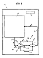
- FIG. 1 schematically shows a laundry drying device 1 with a laundry drum 2, which is fluidically coupled to a recirculation or process air duct 3.
- process air a heated from the circulating air duct 3 into the laundry drum 2 is typically blown by means of a circulating air blower, not shown here.
- the process air absorbs moisture there by releasing heat and is again sucked out of the laundry drum 2 into the recirculating air duct 3 where it is initially cooled in order to at least partially condense out.
- a heat sink 4 is coupled into the recirculating air duct 3, which is flowed out of the laundry drum 2 by means of the moist, warm exhaust air.
- a heater 8 is coupled into the circulating air channel 3. After warming up, the dry-heat process air is blown back to the laundry drum 2.
- the heat sink is designed as an evaporator 4 and the heater is configured as a condenser 8 of a heat pump 6.
- the heat pump 6 also has a compressor 5 and a throttle 14, which are interconnected by means of a coolant c leading coolant line 7 as shown and basically known in a circuit.
- the condenser 8 the refrigerant c is brought from a gaseous to a liquid state, wherein heat is discharged to the process air a.
- the coolant c is fed into the evaporator 4, in which the coolant c is evaporated.
- the evaporator 4 removes heat from the process air a, so that moisture condenses out of the process air a.
- Such condensed moisture is either removed from the device to the outside or collected in a condensate tank, not shown. Possibly. the heat pump or the condenser 8, a further heating, for. B. an electric heater, downstream (not shown).
- control device 9 is in particular configured and / or programmed to determine a moisture content in the process air a in order to control the further operation depending on the moisture content, in particular a heating of the process air and an operating time of a drying process.
- the laundry drying device 1 is equipped with a moisture-determining device, to which at least one temperature sensor 11 or preferably two or more temperature sensors 10 - 13 belong here in addition to the appropriately designed and / or programmed control device 9.
- a moisture-determining device to which at least one temperature sensor 11 or preferably two or more temperature sensors 10 - 13 belong here in addition to the appropriately designed and / or programmed control device 9.
- a first temperature sensor 10 is coupled into the recirculating air duct 3 on the inlet side (upstream) of the evaporator 4, which senses a temperature Ta1; a second temperature sensor 11 is coupled into the circulating air duct 3 on the outlet side (downstream) of the evaporator 4, which senses a temperature Ta2; If a third temperature sensor 12 is coupled into the coolant line 7 on the inlet side (upstream) of the evaporator 4, which senses a temperature Te1, and a fourth temperature sensor 13 is coupled into the coolant line 7 on the outlet side (downstream) of the evaporator 4, which senses a temperature Te2.
- the temperatures or corresponding temperature signals are supplied to the control device 9, so as to close by an indirect procedure from a temperature measurement on the moisture content of the process air a.
- a measurement using only a single temperature sensor namely here the temperature sensor 11 for measuring the temperature Ta2 of the process air a outlet side of the evaporator 4 can be performed.
- the coolant temperature sensors 12, 13 may be used alternatively or additionally, as described in greater detail below.
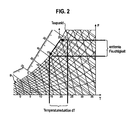
- FIG. 2 shows on the basis of a physiometric diagram, the ratio of moisture content F against a temperature T of the process air a.
- a dew point of the process air a is shown. The higher the temperature T, the higher is the moisture content F when maximum humidity is assumed.
- the process air a cools, it loses moisture accordingly, so that part of the moisture content is removed in accordance with the temperature reduction dT.
- the process air a which is introduced into the laundry drum 2, absorbs an amount of moisture, ideally a moisture amount up to the saturation limit, according to FIG. 2 , Accordingly, the process air a leaves the laundry drum 2 with a high moisture content.
- This process air a with the high moisture content is led to the evaporator 4 of the heat pump 6 and cooled there.
- water or moisture must condense out of the process air a as soon as it reaches the dew point and accordingly there is saturation with the moisture.
- the exchanged heat consists of latent heat to condense the water and sensitive heat to cool the temperature of the process air a or to heat the coolant c in the evaporator 4.
- the latent heat in the evaporator 4 is much higher than the sensible heat.
- the percentage of sensible heat increases relative to the proportion of latent heat.
- the process air is warmed up over time. Accordingly, the moisture content of the process air increases with increasing time until an equilibrium is established and a substantially constant temperature can be measured at various positions of the circulating air channel 3 until the laundry to be dried dries and delivers less moisture to the process air a. If the process is stable and a constant air flow of the process air a and a constant heat exchange in the evaporator 4 are achieved, the temperature exchange of the process air a in the evaporator 4 is higher, while the sensible heat is high or increases, until finally the moisture or the moisture content in the process air a at the outlet of the laundry drum 2 decreases.
- control device 9 can close the moisture content of the process air a and control the drying cycle of the cooling drying device 1 in a coordinated manner.
- the control device 9 with the only one temperature sensor 11 preferably checks to what extent a temperature Ta2 (t) of the process air a develops over time and can be sufficiently dried, for example, from exceeding a previously time-averaged plateau value to determine a certain amount. Namely, when the moisture content decreases after a time of conditions holding the values constant, less latent heat is absorbed by the process air a in the evaporator 4 and more sensible heat is absorbed. Accordingly, the temperature of the process air in the evaporator 4 then decreases more and more.
- the control device 9 it can be detected by suitable programming that the temperature Ta2 (t) of the process air a on the outlet side of the evaporator 4 decreases over time and thus the moisture content of the process air a decreases.
- this effect can not be determined so precisely, since process and environmental changes are not easily compensated.
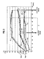
- FIG. 3 shows an example of a drying cycle in a laundry drying apparatus 1 according to FIG. 1 , wherein temperature profiles of the process air a are shown at different points in the air duct 3.
- the respective temperature T is plotted over the course of time t. Since 2 temperature sensors were used at the respective measuring points for experimental purposes, 2 measured curves for the respective temperature value are correspondingly shown in a single position. The highest temperature values are reached by curves k1 at the inlet of the laundry drum 2 and the outlet of the condenser 8.
- the process air a is still relatively cold during the first 40 to 50 minutes, for example, and is passed through the condenser 8, and possibly another, Heating device, not shown, increasingly heated until a plateau value is reached in the region of a plateau p under constant operating conditions.
- the plateau p extends over a period of about 40 to 50 minutes to over 90 minutes and corresponds to the length of time during which about constant conditions prevail in the laundry dryer, since a uniform amount of moisture is released from the laundry to the process air a and a uniform amount of moisture in the evaporator 4 is withdrawn from the process air a.
- the laundry absorbs correspondingly more heat, so that the temperature k1 at the entrance of the laundry drum 2 gradually decreases until the drying cycle is completed.
- the temperature Ta1 of the process air a is shown on the inlet side of the evaporator 4 or on the outlet side of the laundry drum 2. Until the constant operating conditions or the plateau p are reached, this temperature Ta1 gradually increases. At the plateau p it reaches a more or less constant temperature plateau value Ta1p. At the end of the plateau p or in particular behind the plateau p, the temperature Ta1 increases with increasing degree of drying of the clothing the laundry drum 2 and correspondingly less moisture absorption of the process air a gradually increases.
- the temperature plateau Ta1p is in the example shown in a range between just under 40 ° C and 5 ° C.
- threshold values surrounding such plateau values are preferably determined and considered by the control device 9 in order to take account of these natural conditions.
- the temperature Ta2 of the process air a measured at the evaporator 4 on the outlet side.
- the process air a is strongly cooled by the evaporator 4 and takes only a few minutes continuously until reaching the plateau p temperature.
- a temperature plateau Ta2p this temperature Ta2 outlet side of the evaporator 4 is about 25 - 30 ° C. If the laundry increasingly emits less moisture to the process air a, the process air a is increasingly cooled by the evaporator 4 again, so that the temperature Ta2 of the process air a on the outlet side of the evaporator 4 after the end of the plateau p falls again or assumes lower values ,
- an analysis of both the inlet-side and the outlet-side temperatures Ta1 and Ta1 of the process air a at the evaporator 4 or heat sink 4 is preferably carried out.
- the controller 9 much more prominent than the analysis of the individual temporal temperature curves Ta1 (t), Ta2 (t) can be evaluated according to their difference.
- a temperature difference dT1 between the inlet and outlet side temperatures Ta2-Ta1 is significantly lower than a temperature difference dT2 between these temperature values after the plateau p.
- the two temperature differences dT1, dT2 are illustrated by arrows in the diagram.
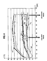
- FIG. 4 illustrates such a situation. Accordingly, a laundry drying apparatus with a cooling body or evaporator 4 that is as effective as possible is preferably able to recognize the detection of the temperature variations over time or the temperature differences over time as well as possible.
- FIG. 4 are the same reference numerals as in FIG. 3 so that with regard to explanations to the explanations to FIG. 3 is referenced. Visible is unlike FIG. 3 in that the temperature differences are less pronounced and that the temperatures in the plateau region are slightly different from those according to FIG. 3 differ.
- a heat exchange efficiency in the heat pump also depends on the relative moisture content of the process air a conducted through the evaporator 4.
- the process air a with a higher moisture content has a better heat exchange efficiency.
- the heat exchanger or heat pump has a decreasing heat exchange performance.
- heat exchange efficiency can be determined. This efficiency changes according to the above statements during the drying cycle.
- the temperature sensors 12, 13, which are used for detecting the temperature Te1 or Te2 of the coolant c on the inlet side or outlet side of the evaporator 4, spaced from each other at the tube of the evaporator 4 or a corresponding connecting tube spaced from each other, wherein the distance is preferably less is than the length of the effective area of the tube of the evaporator 4.
- another equivalent usable heat sink can be considered.
- the heat exchange or its efficiency deteriorates, so that the coolant takes longer, d. H. a longer distance must flow through the evaporator 4 to completely evaporate. Accordingly, the temperature difference or the temperature difference between a temperature sensor arranged on the inlet side and a specific point of a temperature sensor 13, which is arranged at a distance on the outlet side or from the inlet-side temperature sensor 12, decreases. This can be taken as a measure of the moisture content of the process air a or of the laundry still to be dried.
- a number of two temperature sensors 12, 13 are arranged on the cooling circuit, since an in FIG. 5 sketched difference formation dTc1, DTc2 of the temperatures Te2 - Te1 of the coolant c on the outlet side or inlet side of the evaporator 4 has a higher significance than a single over the time t considered temperature value.
- An application of two temperature sensors is still much cheaper in terms of design and cost than providing a humidity directly measuring humidity sensor. According to a less preferred embodiment, however, the measurement with only a single temperature sensor 13 in the region of the evaporator 4 or the condenser 8 can be implemented.
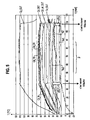
- FIG. 5 shows an example of a diagram comparable to the diagrams FIG. 3 and FIG. 4 , However, temperature profiles of the temperature T of the coolant c over the time t are shown. Recognizable are again plateaus p in a range in which constant operating conditions are set.
- the individual temperature profiles are increasing or decreasing.
- the temperature difference dTc2 on the outlet side is again clearly visible on the inlet side compared to the temperature difference dTc1 on the inlet side.
- the criterion for a drying laundry is not an increase in the temperature differences dTc1, dTc2 but a decrease in the temperature differences dTc1, dTc2.
- a temperature Te1 of the coolant c on the inlet side of the evaporator is with the first of these in FIG. 1 sketched temperature sensors 12, which detects the coolant temperature on the inlet side or in front of the evaporator 4.
- the second of these temperature sensors 13 for determining the temperature differences dTc1, dTc2 is arranged on a three-quarter length of the evaporator 4 or its effective evaporator length.
- exemplary temperatures shown are: a temperature Cp_OUT measured at the outlet of the compressor 8, temperatures Cd_3 / 4, Cd_7 / 8 at three quarters and seven-eighths of the length of the condenser and a temperature Cd_OUT at the outlet of the condenser 8.
- a temperature Cp_OUT measured at the outlet of the compressor 8 temperatures Cd_3 / 4, Cd_7 / 8 at three quarters and seven-eighths of the length of the condenser and a temperature Cd_OUT at the outlet of the condenser 8.
- Cd_air_OUT at the outlet of the condenser
- a temperature Cd_IN at the inlet of the compressor
- Ev_OUT outlet side temperature
- ambient temperature K2 ambient temperature
- a detection of the degree of drying by means of temperature sensing is also suitable for exhaust air dryer.
- the method is also applicable to both separate tumble drier and washer-dryer.
Landscapes
- Engineering & Computer Science (AREA)
- Textile Engineering (AREA)
- Control Of Washing Machine And Dryer (AREA)
- Detail Structures Of Washing Machines And Dryers (AREA)
Abstract
Description
Die Erfindung betrifft ein Wäschetrocknungsgerät mit einer Wäschetrommel, einer Feuchtigkeitsbestimmungseinrichtung zum Bestimmen eines Feuchtegehalts von aus der Wäschetrommel abgeführter Prozessluft und einem Kühlkörper zum Kühlen der Prozessluft, wobei die Feuchtigkeitsbestimmungseinrichtung mindestens einen Temperatursensor aufweist, und der mindestens eine Temperatursensor hinter einem Einlass des Kühlkörpers für ein den Kühlkörper durchströmendes Medium oder ein in dem Kühlkörper befindliches Medium angeordnet ist.The invention relates to a laundry drying apparatus having a laundry drum, a moisture determination device for determining a moisture content of the process air discharged from the laundry drum and a cooling body for cooling the process air, wherein the moisture determination device has at least one temperature sensor, and the at least one temperature sensor behind an inlet of the heat sink for a Cooling medium flowing through or arranged in the heat sink medium is arranged.
Außerdem betrifft die Erfindung ein Verfahren zum Betreiben eines Wäschetrocknungsgerätes, bei dem ein Feuchtegehalt von aus einer Wäschetrommel abgeführter Prozessluft bestimmt wird und mit einem Kühlkörper aus der Prozessluft die Feuchte zumindest teilweise auskondensiert wird, wobei die Feuchtigkeits-Bestimmung durch Messen zumindest einer Temperatur für ein den Kühlkörper durchströmendes Medium oder ein in dem Kühlkörper befindliches Medium und durch Auswerten der gemessenen Temperatur bestimmt wird.In addition, the invention relates to a method for operating a laundry drying apparatus in which a moisture content of discharged from a laundry drum process air is determined and at least partially condensed with a heat sink from the process air humidity, wherein the moisture determination by measuring at least one temperature for a Cooling medium flowing through or a medium in the heat sink and determined by evaluating the measured temperature.
Ein solches Wäschetrocknungsgerät und ein solches Verfahren gehen hervor aus der Schrift
Aus der Schrift
Aus der Schrift
Allgemein bekannt ist ein Wäschetrocknungsgerät mit einer Wäschetrommel, einer Feuchtigkeitsbestimmungseinrichtung zum Bestimmen eines Feuchtegehalts von aus der Wäschetrommel abgeführter Prozessluft und mit einem Kühlkörper zum Kühlen der Prozessluft. Aus der Prozessluft kondensiertes Wasser wird in einem Flüssigkeitsbehältnis aufgefangen oder über einen Wasserauslass abgeführt. Dabei sind Wäschetrocknungsgeräte bekannt, welche als Kondensationstrockner bezeichnet werden und einen Kühlkörper aufweisen, welcher vor der Inbetriebnahme des Wäschetrocknungsgerätes mit einem Kühlmittel gefüllt wird. Vorzugsweise handelt es sich dabei um Leitungswasser, welches in einen Kühlkörper eingelassen wird und bei Bedarf erneuert wird.Generally known is a laundry drying apparatus with a laundry drum, a moisture determination device for determining a moisture content of discharged from the laundry drum process air and a heat sink for cooling the process air. Water condensed from the process air is collected in a liquid container or discharged via a water outlet. In this case, laundry drying devices are known, which are referred to as condensation dryer and have a heat sink, which is filled with a coolant before the start of the laundry dryer. Preferably, this is tap water, which is embedded in a heat sink and renewed when needed.
Weiterhin gibt es Wäschetrocknungsgeräte, welche eine Wärmepumpe aufweisen, um einen Feuchtegehalt in der Prozessluft auszukondensieren. Solche Wärmepumpen bestehen insbesondere aus einem Kompressor bzw. Verflüssiger zum Verflüssigen eines Kühlmittels und aus einem Verdampfer zum Verdampfen des Kühlmittels. An dem Verdampfer vorbeigeführte Prozessluft wird entsprechend abgekühlt, so dass darin enthaltene Feuchte zumindest teilweise auskondensiert.Furthermore, there are laundry drying devices, which have a heat pump to condense a moisture content in the process air. Such heat pumps consist in particular of a compressor or condenser for liquefying a coolant and of an evaporator for evaporating the coolant. Process air passed past the evaporator is cooled correspondingly, so that moisture contained therein at least partially condenses out.
Solche Wäschetrocknungsgeräte sind zum Trocknen von Wäsche ausgestaltet, und werden mittels einer Steuereinrichtung so gesteuert, dass sie eine verbleibende Feuchtigkeit in der Wäsche erfassen können, um den Trocknungsprozess automatisch zu stoppen, wenn eine ausreichende Trocknung erzielt ist. Dadurch können eine Trocknungsdauer und entsprechend ein Energieverbrauch reduziert werden. Um dies zu ermöglichen, sind solche Wäschetrocknungsgeräte mit einer Feuchtigkeitsbestimmungseinrichtung ausgestaltet, welche in Form eines Feuchtigkeitssensors in Verbindung mit der Steuereinrichtung eine Feuchtigkeit direkt in der die Wäschetrommel verlassenden Prozessluft messen. Entsprechende Feuchtesensoren gibt es abhängig vom Hersteller in unterschiedlicher Ausgestaltung und Technologie. Stets wird durch solche Feuchtesensoren jedoch eine direkte Messung der Feuchtigkeit bzw. des Feuchtegehalts von aus der Wäschetrommel abgeführter Prozessluft gemessen. Nachteilig ist dabei, dass es sich bei den Feuchtesensoren um aufwendig herzustellende und entsprechend kostenintensive Komponenten handelt.Such clothes drying devices are designed for drying laundry, and are controlled by a controller so that they can detect a remaining moisture in the laundry to automatically stop the drying process when sufficient drying is achieved. As a result, a drying time and corresponding energy consumption can be reduced. In order to make this possible, such laundry drying devices are designed with a moisture-determining device which, in the form of a moisture sensor in conjunction with the control device, measures moisture directly in the process air leaving the laundry drum. Corresponding humidity sensors are available depending on the manufacturer in different design and technology. However, a direct measurement of the moisture or moisture content of process air discharged from the laundry drum is always measured by such humidity sensors. The disadvantage here is that the humidity sensors are complicated to manufacture and correspondingly expensive components.
Es ist die Aufgabe der vorliegenden Erfindung, ein Wäschetrocknungsgerät mit einer Feuchtigkeitsbestimmungseinrichtung bzw. ein Verfahren zum Betreiben eines derartigen Wäschetrocknungsgerätes derart zu verbessern, dass konstruktiv einfachere und dadurch hinsichtlich der Kosten günstigere Komponenten eingesetzt werden können.It is the object of the present invention to improve a laundry drying device with a moisture determination device or a method for operating such a laundry drying device such that structurally simpler and thus more favorable in terms of cost components can be used.
Diese Aufgabe wird gelöst durch ein Wäschetrocknungsgerät mit einer Feuchtigkeitsbestimmungseinrichtung und den weiteren Merkmalen gemäß Patentanspruch 1 bzw. durch ein Verfahren zum Betreiben eines Wäschetrocknungsgerätes gemäß den Merkmalen gemäß Patentanspruch 13. Vorteilhafte Ausgestaltungen sind insbesondere Gegenstand abhängiger Ansprüche.This object is achieved by a laundry drying device with a moisture determination device and the further features according to claim 1 or by a method for operating a laundry drying device according to the features of
In dem erfindungsgemäßen Wäschetrocknungsgerät mit einer Wäschetrommel, einer Feuchtigkeitsbestimmungseinrichtung zum Bestimmen eines Feuchtegehalts von aus der Wäschetrommel abgeführter Prozessluft und einem Kühlkörper zum Kühlen der Prozessluft, wobei die Feuchtigkeitsbestimmungseinrichtung mindestens einen Temperatursensor aufweist, und der mindestens eine Temperatursensor hinter einem Einlass des Kühlkörpers für ein den Kühlkörper durchströmendes Medium oder ein in dem Kühlkörper befindliches Medium angeordnet ist, ist demnach das Medium ausgewählt aus der Gruppe enthaltend die Prozessluft und ein Kühlmittel, ist der mindestens eine Temperatursensor zum Messen einer Auslass-Temperatur des Mediums auslassseitig des Kühlkörpers angeordnet und ist ein weiterer Temperatursensor zum Messen einer Einlass-Temperatur des Mediums einlassseitig des Kühlkörpers angeordnet.In the laundry drying apparatus according to the invention with a laundry drum, a moisture determination device for determining a moisture content of the process air discharged from the laundry drum and a cooling body for cooling the process air, wherein the moisture determination device has at least one temperature sensor, and the at least one temperature sensor behind an inlet of the heat sink for a heat sink Accordingly, the medium is selected from the group containing the process air and a coolant, the at least one temperature sensor for measuring an outlet temperature of the medium is arranged on the outlet side of the heat sink and is another temperature sensor for Measuring an inlet temperature of the medium disposed on the inlet side of the heat sink.
Eine solche Anordnung ermöglicht es, den Einsatz eines teuren Feuchtesensors zu umgehen, da anstelle eines Feuchtesensors zur direkten Messung eines Feuchtegehalts zumindest ein Temperatursensor zur indirekten Bestimmung des Feuchtegehalts eingesetzt wird. Zudem kann dadurch eine Lebensdauer des bzw. der Sensoren im Vergleich zu einem Feuchtesensor erreicht werden. Die Temperatursensoren brauchen, im Gegensatz zu dedizierten Feuchtesensoren, nicht gekühlt zu werden, und eine Erfassungsgenauigkeit wird erhöht.Such an arrangement makes it possible to circumvent the use of an expensive humidity sensor, since at least one temperature sensor is used for the indirect determination of the moisture content instead of a humidity sensor for the direct measurement of a moisture content. In addition, a lifetime of the sensor or sensors can be achieved in comparison to a humidity sensor. The temperature sensors, unlike dedicated humidity sensors, do not need to be cooled and detection accuracy is increased.
Der mindestens eine Temperatursensor ist hinter einem Einlass des Kühlkörpers für ein den Kühlkörper durchströmendes Medium (z. B. Prozessluft oder Kühlmittel) oder für ein sich in dem Kühlkörper befindliches Medium (z. B. Kühlmittel) angeordnet. Bei einer solchen Anordnung hat die Prozessluft bereits latente Wärme an das Kühlmittel übertragen können, so dass Feuchtigkeit aus der Prozessluft auskondensieren konnte.The at least one temperature sensor is arranged behind an inlet of the heat sink for a medium flowing through the heat sink (eg, process air or coolant) or for a medium (eg, coolant) located in the heat sink. At a In such an arrangement, the process air has already been able to transfer latent heat to the coolant, so that moisture could condense out of the process air.
Bevorzugt wird, dass der mindestens eine Temperatursensor zum Messen einer Temperatur der Prozessluft auslassseitig des Kühlkörpers angeordnet ist. Bei Messung der Temperatur der Prozessluft kann unter auslassseitig des Kühlkörpers sowohl verstanden werden, dass der Temperatursensor noch innerhalb einer Kühlstrecke des Kühlkörpers angeordnet ist, als auch vorzugsweise verstanden werden, dass der Temperatursensor außerhalb hinter einer Kühlstrecke des Kühlkörpers angeordnet ist. Wichtig ist, dass die Prozessluft bereits zumindest so viel latente Wärme an das Kühlmittel übertragen konnte, dass Feuchtigkeit aus der Prozessluft auskondensieren konnte. Da eine Überhitzung von zu trocknender Kleidung üblicherweise nicht zu befürchten ist, solange diese noch nass ist und die Prozessluft bis vorzugsweise zur Sättigung mit Feuchte angereichert wird, reicht der Einsatz eines einzelnen solchen Temperatursensors aus.It is preferred that the at least one temperature sensor for measuring a temperature of the process air is arranged on the outlet side of the heat sink. When measuring the temperature of the process air, the outlet side of the heat sink can both be understood as meaning that the temperature sensor is still arranged within a cooling section of the heat sink, and preferably understood to be arranged outside the cooling section of the heat sink. It is important that the process air could transfer at least as much latent heat to the coolant that moisture could condense out of the process air. Since overheating of clothing to be dried is usually not to be feared, as long as it is still wet and the process air is preferably enriched to saturation with moisture, the use of a single such temperature sensor is sufficient.
Der mindestens eine Temperatursensor ist insbesondere hinter einem Kühlmitteleinlass des Kühlkörpers zum Messen einer Temperatur eines durch den Kühlkörper strömenden Kühlmittels angeordnet (z. B. bei einem Wärmetauscher).The at least one temperature sensor is in particular arranged behind a coolant inlet of the heat sink for measuring a temperature of a coolant flowing through the heat sink (eg in the case of a heat exchanger).
Zusätzlich oder alternativ dazu kann der mindestens eine Temperatursensor hinter einem Kühlmitteleinlass des Kühlkörpers zum Messen einer Temperatur eines in dem Kühlkörper befindlichen Kühlmittels angeordnet sein (z. B. bei einigen wassergekühlten Kühlkörpern). Bei Messung der Temperatur des Kühlmittels kann unter auslassseitig des Kühlmittels sowohl verstanden werden, dass der Temperatursensor noch vorzugsweise innerhalb einer Kühlstrecke des Kühlkörpers angeordnet ist, als auch verstanden werden, dass der Temperatursensor außerhalb hinter einer Kühlstrecke des Kühlkörpers angeordnet ist. Entscheidend ist wieder, dass die Prozessluft hinter einem relativ dazu einlassseitigen Temperatursensor bereits zumindest so viel latente Wärme an das Kühlmittel übertragen konnte, dass Feuchtigkeit aus der Prozessluft auskondensieren konnte. Eine solche Anordnung kann als Wärmepumpe ausgestaltet sein, bei welcher ein Kühlmittel durch einen Verdampfer strömt. Möglich ist auch eine Ausgestaltung in einem sogenannten Kondensationstrockner, bei welchem ein Kühlmittel, z.B. Leitungswasser, nach Bedarf in einen Kühlkörper eingelassen wird.Additionally or alternatively, the at least one temperature sensor may be arranged behind a coolant inlet of the heat sink for measuring a temperature of a coolant located in the heat sink (eg in the case of some water-cooled heat sinks). When measuring the temperature of the coolant can be understood by the outlet side of the coolant both that the temperature sensor is preferably disposed within a cooling path of the heat sink, as well as be understood that the temperature sensor is arranged outside behind a cooling path of the heat sink. It is again crucial that the process air behind a relative inlet temperature sensor could already transmit at least as much latent heat to the coolant that moisture could condense out of the process air. Such an arrangement can be configured as a heat pump, in which a coolant flows through an evaporator. Also possible is an embodiment in a so-called condensation dryer, in which a coolant, for example tap water, is admitted as required into a heat sink.
Die Feuchtigkeitsbestimmungseinrichtung ist bevorzugt ausgelegt und/oder programmiert zum Bestimmen des Feuchtegehalts anhand einer zeitlichen Abfolge mittels des Temperatursensors gemessener Temperaturen.The moisture determination device is preferably designed and / or programmed for determining the moisture content based on a temporal sequence by means of the temperature sensor measured temperatures.
Insbesondere ist die Feuchtigkeitsbestimmungseinrichtung ausgelegt und/oder programmiert zum Bestimmen eines - bezogen auf den Kühlkörper - einlassseitigen Anstiegs und / oder eines auslassseitigen Abfalls der Temperatur der Prozessluft oder des Kühlmittels über die zeitliche Abfolge gemessener Temperaturen der Prozessluft gegenüber einem vorherigen Temperatur-Plateauwert der Prozessluft bzw. des Kühlmittels. Solange die Prozessluft mit gleichmäßigem Feuchtigkeitsgehalt zum Kühlkörper geführt wird, zieht der Kühlkörper eine gleichmäßige Menge an Feuchtigkeit aus der Prozessluft. Entsprechend bleiben die messbaren Temperaturen im Wesentlichen konstant. Bei einer Reduzierung des Feuchtegehalts in der Prozessluft aufgrund von in dem Wäschetrocknungsgerät trocken werdender Kleidung gibt die Prozessluft jedoch nicht mehr nur latente sondern zunehmend mehr sensible Wärme an das Kühlmittel. Im Fall der Messung der Temperatur der Prozessluft kann somit aus einem Abfallen der Temperatur an insbesondere dem Auslass des Verdampfers bzw. Kühlkörpers über die Zeit auf einen sich reduzierenden Feuchtigkeitsgehalt der Prozessluft geschlossen werden. Im Fall der Messung der Temperatur des Kühlmittels kann entsprechend aus einem Anstieg der Temperatur über die Zeit auf einen sich reduzierenden Feuchtigkeitsgehalt der Prozessluft geschlossen werden. Es kann auch die Temperaturdifferenz zwischen einlassseitiger Temperatur und auslassseitiger Temperatur des Kühlkörpers erfasst und zur Festestellung eines Feuchtigkeitsgehalts (Trocknungsgrads) verwendet werden. Dies kann vorzugsweise mittels Bezugs auf einen Temperaturdifferenz-Plateauwert, aber auch in absoluten Größen der Temperaturdifferenz (z. B. durch Über- bzw. Unterschreiten eines Temperaturdifferenzschwellwerts), geschehen.In particular, the moisture determination device is designed and / or programmed for determining an inlet-side rise and / or an outlet-side drop in the temperature of the process air or the coolant over the time sequence of measured temperatures of the process air compared to a previous temperature plateau value of the process air or of the coolant. As long as the process air is led to the heat sink with a uniform moisture content, the heat sink draws an even amount of moisture from the process air. Accordingly, the measurable temperatures remain substantially constant. However, if the moisture content in the process air is reduced due to clothes becoming dry in the laundry drying machine, the process air no longer gives only latent but increasingly more sensible heat to the coolant. In the case of the measurement of the temperature of the process air can thus be concluded from a drop in temperature, in particular the outlet of the evaporator or heat sink over time to a reducing moisture content of the process air. In the case of measuring the temperature of the coolant, it can be concluded accordingly from an increase in the temperature over time to a reducing moisture content of the process air. Also, the temperature difference between the inlet-side temperature and the outlet-side temperature of the heat sink can be detected and used for determining a moisture content (degree of drying). This can preferably be done by reference to a temperature difference plateau value, but also in absolute terms of the temperature difference (eg by exceeding or falling below a temperature difference threshold value).
Aufgrund geräte- und verfahrensbedingter Schwankungen ist dabei unter dem Temperatur-Plateauwert ein gemittelter Wert jeweils einer Abfolge einzelner aufeinanderfolgender Messwerte zu verstehen. Entsprechend können auch Schwellwerte festgelegt werden, deren Über- oder Unterschreitung als Indikator für ein Abfallen der Prozesslufttemperatur oder ein Ansteigen der Kühlmitteltemperatur angesetzt wird.Due to device- and process-related fluctuations, the temperature-plateau value means an average value of a succession of individual successive measured values. Accordingly, threshold values can also be defined whose overshoot or undershoot is used as an indicator for a fall in the process air temperature or an increase in the coolant temperature.
Der mindestens eine Temperatursensor kann zum Messen einer Temperatur der Prozessluft auslassseitig des Kühlkörpers angeordnet sein und ein weiterer Temperatursensor kann zum Messen einer Einlass-Temperatur der Prozessluft einlassseitig des Kühlkörpers angeordnet sein. Der mindestens eine Temperatursensor kann gemäß einer weiteren Ausgestaltung zum Messen einer Temperatur eines durch den Kühlkörper strömenden Kühlmittels oder eines sich in dem Kühlkörper befindlichen Kühlmittels hinter einem Kühlmitteleinlass des Kühlkörpers angeordnet sein und ein weiterer Temperatursensor kann dann zum Messen einer Einlass-Temperatur des Kühlmittels einlassseitig des Kühlkörpers angeordnet sein. Dadurch werden gemäß entsprechender auch kombiniert einsetzbarer Ausgestaltungen zwei Messwerte der Prozessluft oder des Kühlmittels im Bereich des Einlasses bzw. im Bereich des Auslasses des Kühlkörpers bereitgestellt, deren Differenzwert ein genaueres Maß zum Bestimmen der Entfeuchtungsleistung des Kühlkörpers bereitstellt. Indirekt kann darüber entsprechend auch genauer auf einen Feuchtigkeitsgehalt der aus der Wäschetrommel strömenden Prozessluft geschlossen werden als in dem Fall nur eines einzelnen, insbesondere auslassseitigen, Temperatursensors.The at least one temperature sensor can be arranged for measuring a temperature of the process air on the outlet side of the heat sink, and a further temperature sensor can be arranged for measuring an inlet temperature of the process air on the inlet side of the heat sink. The at least one temperature sensor may be arranged behind a coolant inlet of the heat sink downstream of a coolant inlet of the heat sink according to a further embodiment for measuring a temperature of a flowing through the cooling body coolant or a coolant located in the heat sink and a further temperature sensor may then for measuring an inlet temperature of the coolant inlet side of the Heat sink can be arranged. As a result, two measured values of the process air or of the coolant in the region of the inlet or in the region of the outlet of the heat sink are provided according to corresponding embodiments which can also be used in combination, the difference value of which provides a more accurate measure for determining the dehumidifying performance of the heat sink. Indirectly, it is accordingly also possible to more accurately conclude a moisture content of the process air flowing out of the laundry drum than in the case of only a single, in particular outlet-side, temperature sensor.
Der Kühlkörper ist bevorzugt dimensioniert und/oder eine Steuereinrichtung ist bevorzugt ausgestaltet und/oder programmiert, den Kühlkörper derart mit Kühlmittel zu durchströmen, dass bis zu dem mindestens einen Temperatursensor nicht der gesamte Feuchtegehalt aus der Prozessluft gezogen wird.The heat sink is preferably dimensioned and / or a control device is preferably configured and / or programmed to flow through the heat sink with coolant such that not all of the moisture content is drawn from the process air up to the at least one temperature sensor.
Der Kühlkörper kann insbesondere durch einen Verdampfer einer Wärmepumpe ausgebildet sein.The heat sink may be formed in particular by an evaporator of a heat pump.
Der mindestens eine Temperatursensor ist bevorzugt ein Sensor einer Heizeinrichtungssteuerung zum Steuern einer Prozesslufttemperatur. Besonders vorteilhaft kann somit ein üblicherweise bereits vorhandener Temperatursensor eingesetzt werden, so dass nicht nur ein Feuchtesensor entfallen kann sondern in einfachster Ausgestaltung nicht einmal ein zusätzlicher Temperatursensor einzusetzen ist.The at least one temperature sensor is preferably a sensor of a heater controller for controlling a process air temperature. Thus, a usually already existing temperature sensor can be used particularly advantageously so that not only a humidity sensor can be dispensed with, but even an additional temperature sensor can not even be used in the simplest configuration.
Eine eigenständige Lösung der vorliegenden Aufgabe ist erfindungsgemäß auch Verfahren zum Betreiben eines Wäschetrocknungsgerätes, bei dem ein Feuchtegehalt von aus einer Wäschetrommel abgeführter Prozessluft bestimmt wird und mit einem Kühlkörper aus der Prozessluft die Feuchte zumindest teilweise auskondensiert wird, wobei die Feuchtigkeits-Bestimmung durch Messen zumindest einer Temperatur für ein den Kühlkörper durchströmendes Medium oder ein in dem Kühlkörper befindliches Medium und durch Auswerten der gemessenen Temperatur bestimmt wird, bei welchem Verfahren das Medium ausgewählt ist aus der Gruppe enthaltend die Prozessluft und ein Kühlmittel, und bei welchem Verfahren der Feuchtegehalt durch Messen einer Auslass-Temperatur des Mediums auslassseitig des Kühlkörpers und durch Messen einer Einlass-Temperatur des Mediums einlassseitig des Kühlkörpers bestimmt wird.An independent solution of the present task is according to the invention also methods for operating a laundry drying device, wherein a moisture content is determined by deducted from a laundry drum process air and the moisture is at least partially condensed out with a heat sink from the process air, the moisture determination by measuring at least one temperature for the heat sink flowing medium or a medium located in the heat sink and by evaluating the measured Temperature is determined in which method the medium is selected from the group containing the process air and a coolant, and in which method the moisture content by measuring an outlet temperature of the medium outlet side of the heat sink and by measuring an inlet temperature of the medium inlet side of the heat sink is determined.
Zur Feuchtigkeits-Bestimmung wird dabei bevorzugt eine Temperaturdifferenz einer auslassseitig des Kühlkörpers gemessenen Temperatur und einer einlassseitig des Kühlkörpers gemessenen Temperatur gebildet.For moisture determination, a temperature difference of a temperature measured on the outlet side of the heat sink and a temperature measured on the inlet side of the heat sink is preferably formed.
Der Feuchtegehalt wird bevorzugt anhand einer zeitlichen Abfolge gemessener Temperaturen oder Temperaturdifferenzen bestimmt. Insbesondere wird bei einem einlassseitigen Anstieg und / oder einem auslassseitigen Abfall der Temperatur der Prozessluft über die zeitliche Abfolge gemessener Temperaturen oder Temperaturdifferenzen der Prozessluft gegenüber einem vorherigen Temperatur- bzw. Temperaturdifferenz-Plateauwert der Prozessluft ein abnehmender Feuchtegehalt indiziert. Zusätzlich oder alternativ kann auch bei einem einlassseitigen Abfall und / oder auslassseitigen Anstieg der Temperatur des Kühlmittels über die zeitliche Abfolge gemessener Temperaturen des Kühlmittels gegenüber einem vorherigen Temperatur-Plateauwert des Kühlmittels ein abnehmender Feuchtegehalt der Prozessluft indiziert werden.The moisture content is preferably determined on the basis of a chronological sequence of measured temperatures or temperature differences. In particular, in the case of an inlet-side rise and / or an outlet-side drop in the temperature of the process air over the chronological sequence of measured temperatures or temperature differences of the process air relative to a previous temperature or temperature difference plateau value of the process air, a decreasing moisture content is indicated. Additionally or alternatively, even with an inlet-side drop and / or outlet-side rise in the temperature of the coolant over the chronological sequence of measured temperatures of the coolant with respect to a previous temperature plateau value of the coolant, a decreasing moisture content of the process air can be indicated.
Ein solches Wäschetrocknungsgerät bzw. ein Verfahren zum Betreiben eines Wäschetrocknungsgerätes mit derartigen Verfahrensschritten bietet nicht nur eine Reduzierung der Kosten durch den Einsatz von kostengünstigen Temperatursensoren anstelle von Feuchtigkeitssensoren. Überraschenderweise ist auch eine längere Lebensdauer des Gerätes aufgrund der höheren Lebensdauer der Temperatursensoren gegenüber Feuchtigkeitssensoren erzielbar. Ein weiterer Vorteil besteht darin, dass solche Temperatursensoren im Gegensatz zu Feuchtigkeitssensoren nicht gekühlt werden müssen, was den Aufbau und den Betriebsaufwand weiter vereinfacht. Überraschenderweise ist sogar eine höhere Genauigkeit erzielbar, wenn eine derartige indirekte Messung über gemessene Temperaturen anstelle einer direkten Feuchtigkeitsmessung durchgeführt wird.Such a laundry drying apparatus or a method for operating a laundry drying apparatus with such method steps not only offers a reduction in costs through the use of inexpensive temperature sensors instead of moisture sensors. Surprisingly, a longer life of the device due to the higher life of the temperature sensors relative to humidity sensors can be achieved. Another advantage is that such temperature sensors, in contrast to moisture sensors do not need to be cooled, which further simplifies the construction and operating costs. Surprisingly, even greater accuracy is achievable when such indirect measurement is performed over measured temperatures rather than direct moisture measurement.
Ausführungsbeispiele der Erfindung werden nachfolgend anhand der Zeichnung schematisch näher erläutert. Es zeigen:
- FIG 1
- ein Wäschetrocknungsgerät mit Komponenten zum Ausbilden einer Feuchtigkeitsbestimmungseinrichtung auf Basis einer indirekten Temperaturmessung;
- FIG 2
- ein Diagramm zur Veranschaulichung eines Verhältnisses von Temperatur einer Prozessluft im Verhältnis zu deren Feuchtegehalt;
- FIG 3
- ein Diagramm mit einer Vielzahl von Temperaturkurven insbesondere von Prozessluft in einem Wäschetrocknungsgerät gemäß
FIG 1 über der Zeit aufgetragen; - FIG 4
- ein weiteres derartiges Diagramm bei Einsatz eines Wärmeaustauschers mit einem im Vergleich zu
FIG 3 geringeren Wirkungsgrad; und - FIG 5
- ein weiteres Diagramm, bei welchem Kurven einer Kühlmitteltemperatur über der Zeit aufgetragen sind.
- FIG. 1
- a laundry drying apparatus having components for forming a humidity determining device based on an indirect temperature measurement;
- FIG. 2
- a diagram illustrating a ratio of temperature of a process air in relation to their moisture content;
- FIG. 3
- a diagram with a variety of temperature curves in particular of process air in a laundry drying apparatus according to
FIG. 1 applied over time; - FIG. 4
- another such diagram when using a heat exchanger with a compared to
FIG. 3 lower efficiency; and - FIG. 5
- another diagram in which curves of a coolant temperature over time are plotted.
In der gezeigten Ausgestaltung ist der Kühlkörper als Verdampfer 4 und ist die Heizung als Verflüssiger 8 einer Wärmepumpe 6 ausgestaltet. Die Wärmepumpe 6 weist ferner einen Verdichter 5 und eine Drossel 14 auf, die mittels einer Kühlmittel c führenden Kühlmittelleitung 7 wie gezeigt und grundsätzlich bekannt in einem Kreislauf zusammengeschaltet sind. In dem Verflüssiger 8 wird das Kühlmittel c aus einem gasförmigen in einen flüssigen Zustand gebracht, wobei Wärme an die Prozessluft a abgegeben wird. Nachfolgend wird das Kühlmittel c in den Verdampfer 4 geführt, in welchem das Kühlmittel c verdampft wird. Entsprechend entzieht der Verdampfer 4 der Prozessluft a Wärme, so dass aus der Prozessluft a Feuchtigkeit auskondensiert. Derart auskondensierte Feuchtigkeit wird entweder aus dem Gerät nach außen abgeführt oder in einem nicht dargestellten Kondensatbehälter aufgefangen. Ggf. kann der Wärmepumpe bzw. dem Verflüssiger 8 eine weitere Heizung, z. B. eine Elektroheizung, nachgeschaltet sein (ohne Abb.).In the embodiment shown, the heat sink is designed as an
Zur Steuerung diverser Funktionen eines solchen Wäschetrocknungsgeräts 1 weist dieses eine Steuereinrichtung 9 auf. Die Steuereinrichtung 9 ist insbesondere ausgestaltet und/oder programmiert, einen Feuchtegehalt in der Prozessluft a zu bestimmen, um abhängig vom Feuchtegehalt den weiteren Betrieb zu steuern, insbesondere ein Aufheizen der Prozessluft und eine Betriebsdauer eines Trocknungsvorgangs.To control various functions of such a laundry drying device 1, this has a
Außerdem ist das Wäschetrocknungsgerät 1 mit einer Feuchtigkeitsbestimmungseinrichtung ausgerüstet, zu der hier neben der entsprechend ausgestalteten und/oder programmierten Steuereinrichtung 9 zumindest ein Temperatursensor 11 oder vorzugsweise zwei oder mehr Temperatursensoren 10 - 13 gehören. Mittels der Temperatursensoren 10-13 wird eine entsprechende Temperatur Ta1, Ta2 der Prozessluft a bzw. eine Temperatur Te1, Te2 des Kühlmittels c gemessen. Genauer gesagt ist ein erster Temperatursensor 10 in den Umluftkanal 3 einlassseitig (stromaufwärts) des Verdampfers 4 eingekoppelt, welcher eine Temperatur Ta1 abfühlt; ist ein zweiter Temperatursensor 11 in den Umluftkanal 3 auslassseitig (stromabwärts) des Verdampfers 4 eingekoppelt welcher eine Temperatur Ta2 abfühlt; ist ein dritter Temperatursensor 12 in die Kühlmittelleitung 7 einlassseitig (stromaufwärts) des Verdampfers 4 eingekoppelt, welcher eine Temperatur Te1 abfühlt und ist ein vierter Temperatursensor 13 in die Kühlmittelleitung 7 auslassseitig (stromabwärts) des Verdampfers 4 eingekoppelt, welcher eine Temperatur Te2 abfühlt. Die Temperaturen bzw. entsprechende Temperatursignale werden der Steuereinrichtung 9 zugeführt, um so über eine indirekte Verfahrensweise aus einer Temperaturmessung auf den Feuchtegehalt der Prozessluft a zu schließen.In addition, the laundry drying device 1 is equipped with a moisture-determining device, to which at least one temperature sensor 11 or preferably two or more temperature sensors 10 - 13 belong here in addition to the appropriately designed and / or programmed
Während diese Positionen für die Temperatursensoren 10, 11 besonders bevorzugt werden, können prinzipiell jedoch auch andere Positionen innerhalb des Verdampfers 4 oder im Luftkanal 3 vom Verdampfer 4 beabstandet gewählt werden, solange zwischen diesen Temperatursensoren 10,11 zumindest ein Teilstück der kondensierend wirkenden Strecke des Verdampfers 4 liegt. Da üblicherweise zumindest ein Temperatursensor im Luftkanal 3 zum Messen der Temperatur der Prozessluft a angeordnet ist, um eine Steuerung des Trocknungszyklus zu ermöglichen, braucht entsprechend lediglich ein weiterer zusätzlicher Temperatursensor im Umluftkanal 3 angeordnet zu werden, was wesentlich kostengünstiger ist als die Bereitstellung eines den Feuchtegehalt direkt messenden Feuchtigkeitssensors.While these positions are particularly preferred for the
Gemäß einer alternativen Ausführungsform mit jedoch einem etwas weniger genauem Messergebnis kann auch eine Messung unter Verwendung nur eines einzelnen Temperatursensors, nämlich hier des Temperatursensors 11 zum Messen der Temperatur Ta2 der Prozessluft a auslassseitig des Verdampfers 4 durchgeführt werden.According to an alternative embodiment but with a somewhat less accurate measurement result, a measurement using only a single temperature sensor, namely here the temperature sensor 11 for measuring the temperature Ta2 of the process air a outlet side of the
Die Kühlmitteltemperatursensoren 12,13 können dazu alternativ oder zusätzlich verwendet werden, wie weiter unten genauer beschrieben wird.The
Entsprechend kann in einem Wäschetrocknungsgerät anhand zumindest einer Temperaturmessung festgestellt werden, in welchem Maße der Feuchtegehalt in bzw. an dem Kühlkörper 4 reduziert wurde.Accordingly, it can be determined in a laundry drying device based on at least one temperature measurement to what extent the moisture content in or on the
Wenn ein Wäschetrocknungsgerät mit einer Wärmepumpe 6 eingesetzt wird, z. B. nach
Wenn ein Trocknungsprozess gestartet wird und die in der Wäschetrommel 2 befindliche Wäsche voll Feuchtigkeit ist, absorbiert die Prozessluft a, welche in die Wäschetrommel 2 eingelassen wird, eine Menge der Feuchtigkeit, idealerweise eine Feuchtigkeitsmenge bis zur Sättigungsgrenze, gemäß
Wenn die Prozessluft a längs des Taupunkts weiter abgekühlt wird, findet ein Wärmeaustausch in bzw. mit dem Verdampfer 4 statt. Die ausgetauschte Wärme besteht dabei aus latenter Wärme zum Kondensieren des Wassers und sensibler Wärme zum Abkühlen der Temperatur der Prozessluft a bzw. zum Erwärmen des Kühlmittels c im Verdampfer 4. Zu Beginn eines Trocknungszuflusses, wenn die Feuchtigkeit in der Prozessluft a hoch ist, ist die latente Wärme in dem Verdampfer 4 sehr viel höher als die sensible Wärme. Während die Feuchtigkeit in der Prozessluft a abnimmt, steigt der Prozentsatz bzw. Anteil der sensiblen Wärme relativ zu dem Anteil der latenten Wärme an.When the process air a is further cooled along the dew point, a heat exchange takes place in or with the
Zu Beginn eines Trocknungsvorgangs ist die Prozessluft über die Zeit hinweg aufgewärmt. Entsprechend nimmt der Feuchtegehalt der Prozessluft mit zunehmender Zeit zu, bis sich ein Gleichgewicht einstellt und an verschiedenen Positionen des Umluftkanals 3 eine im Wesentlichen konstante Temperatur messbar ist, bis die zu trocknende Wäsche trocknet und weniger Feuchte an die Prozessluft a abgibt. Wenn der Prozess stabil ist und eine konstante Luftströmung der Prozessluft a und ein konstanter Wärmeaustausch in dem Verdampfer 4 erzielt werden, wird der Temperaturaustausch der Prozessluft a im Verdampfer 4 höher, während die sensible Wärme hoch ist bzw. zunimmt, bis letztendlich die Feuchtigkeit bzw. der Feuchtegehalt in der Prozessluft a an dem Auslass der Wäschetrommel 2 abnimmt.At the beginning of a drying process, the process air is warmed up over time. Accordingly, the moisture content of the process air increases with increasing time until an equilibrium is established and a substantially constant temperature can be measured at various positions of the circulating air channel 3 until the laundry to be dried dries and delivers less moisture to the process air a. If the process is stable and a constant air flow of the process air a and a constant heat exchange in the
Entsprechend kann durch eine Messung der Temperatur der Prozessluft a am Einlass und am Auslass des Verdampfers 4 eine indirekte Messung des Feuchtegehalts der Prozessluft a, wenn diese die Wäschetrommel 2 verlässt, durchgeführt werden. Durch das Bestimmen entsprechender Temperaturwerte kann die Steuereinrichtung 9 auf den Feuchtegehalt der Prozessluft a schließen und den Trocknungszyklus des Kühltrocknungsgerätes 1 darauf abgestimmt steuern.Accordingly, by measuring the temperature of the process air a at the inlet and at the outlet of the
Bei der Ausführungsform aus
Dahingegen prüft die Steuereinrichtung 9 bei der alternativen zweiten Ausführungsform mit dem nur einen Temperatursensor 11 bevorzugt, in welchem Maße sich eine Temperatur Ta2(t) der Prozessluft a über die Zeit gemessen entwickelt und kann eine ausreichende Trocknung beispielsweise aus einem Überschreiten eines vorher zeitlich gemittelten Plateauwerts um einem bestimmten Betrag bestimmen. Wenn der Feuchtegehalt nämlich nach einer Zeit der die Werte konstant haltenden Bedingungen abnimmt, wird von der Prozessluft a im Verdampfer 4 weniger latente Wärme aufgenommen und mehr sensible Wärme aufgenommen. Entsprechend nimmt dann die Temperatur der Prozessluft im Verdampfer 4 zunehmend stärker ab. Entsprechend kann mittels der Steuereinrichtung 9 durch eine geeignete Programmierung erfasst werden, dass die Temperatur Ta2(t) der Prozessluft a auslassseitig des Verdampfers 4 über die Zeit gemessen abnimmt und somit der Feuchtegehalt der Prozessluft a abnimmt. Im Vergleich zur ersten Ausführungsform ist dieser Effekt jedoch nicht so genau bestimmbar, da Prozess- und Umgebungsänderungen nicht einfach kompensierbar sind. So tritt während der Abnahme des Feuchtigkeitsgehalts in der Prozessluft a bei gleicher Heizleistung zum nachfolgenden Aufheizen der Prozessluft a diese mit einer auch reduzierten Temperatur in die Wäschetrommel 2 ein und kann entsprechend weniger Feuchte von der bereits teilweise getrockneten Wäsche annehmen. Bei entsprechender Gegensteuerung kann erreicht werden, dass bei abnehmendem Feuchtegehalt in der Prozessluft auch der Anteil von Wärme, der durch die Prozessluft a an die teilweise getrocknete Wäsche übertragen wird, sich ändert, was letztendlich während des Trocknungszyklus die Temperatur der Prozessluft a am Auslass der Wäschetrommel 2 zunehmen lässt. Dies kann wiederum durch eine sensiblere Kühlung in dem Verdampfer 4 bei reduziertem Feuchtegehalt kompensiert werden.On the other hand, in the alternative second embodiment, the
Weiterhin dargestellt ist die Temperatur Ta1 der Prozessluft a einlassseitig des Verdampfers 4 bzw. auslassseitig der Wäschetrommel 2. Bis zum Erreichen der konstanten Betriebsbedingungen bzw. des Plateaus p nimmt diese Temperatur Ta1 allmählich zu. Beim Plateau p erreicht sie einen mehr oder weniger konstanten Temperatur-Plateauwert Ta1p. Zum Ende des Plateaus p bzw. insbesondere hinter dem Plateau p nimmt die Temperatur Ta1 bei zunehmendem Trockungsgrad der Kleidung in der Wäschetrommel 2 und entsprechend weniger Feuchtigkeitsaufnahme der Prozessluft a allmählich weiter zu. Der Temperatur-Plateauwert Ta1p liegt bei dem dargestellten Beispiel in einem Bereich zwischen knapp 40°C und 5°C.Furthermore, the temperature Ta1 of the process air a is shown on the inlet side of the
Typischerweise werden keine konstant festen Temperatur-Plateauwerte angegeben oder bestimmt, da schon durch die Menge der zu trocknenden Kleidung in der Wäschetrommel 2 und deren ungleichmäßige Rotation stets eine unterschiedliche Menge an Feuchte an die Prozessluft a übertragen wird. Entsprechend werden durch die Steuereinrichtung 9 bevorzugt solche Plateauwerte umgebende Schwellenwerte bestimmt und betrachtet, um diese natürlichen Gegebenheiten zu berücksichtigen.Typically, no constant fixed temperature plateau values are specified or determined, since a different amount of moisture is always transferred to the process air a by the amount of clothes to be dried in the
Dargestellt ist außerdem die am Verdampfer 4 auslassseitig gemessene Temperatur Ta2 der Prozessluft a. Zu Beginn eines Trocknungszyklus, wenn die Prozessluft noch keine nennenswerte Feuchtigkeit aufgenommen hat, wird die Prozessluft a durch den Verdampfer 4 stark abgekühlt und nimmt erst nach wenigen Minuten kontinuierlich bis zum Erreichen des Plateaus p Temperatur an. Ein Temperatur-Plateauwert Ta2p dieser Temperatur Ta2 auslassseitig des Verdampfers 4 liegt bei ca. 25 - 30°C. Wenn die Wäsche zunehmend weniger Feuchtigkeit an die Prozessluft a abgibt, wird die Prozessluft a durch den Verdampfer 4 wieder zunehmend stärker gekühlt, so dass die Temperatur Ta2 der Prozessluft a auslassseitig des Verdampfers 4 nach dem Ende des Plateaus p wieder abfällt bzw. niedrigere Werte annimmt.Also shown is the temperature Ta2 of the process air a measured at the
Entsprechend wird bevorzugt eine Analyse sowohl der einlassseitigen als auch der auslassseitigen Temperaturen Ta1 bzw. Ta1 der Prozessluft a am Verdampfer 4 bzw. Kühlkörper 4 durchgeführt. Durch die Steuereinrichtung 9 wesentlich markanter als die Analyse der einzelnen zeitlichen Temperaturverläufe Ta1(t), Ta2(t) auswertbar ist entsprechend deren Differenz. Während der Dauer des Plateaus p ist eine Temperaturdifferenz dT1 zwischen den einlass- und auslassseitigen Temperaturen Ta2 - Ta1 deutlich geringer als eine Temperaturdifferenz dT2 zwischen diesen Temperaturwerten nach dem Plateau p. Die beiden Temperaturdifferenzen dT1, dT2 sind durch Pfeile in dem Diagramm veranschaulicht.Accordingly, an analysis of both the inlet-side and the outlet-side temperatures Ta1 and Ta1 of the process air a at the
Die beschriebenen Wirkungen hängen in einem hohen Maße auch von der Qualität des Wärmeaustauschers bzw. der Wärmepumpe 6 ab. Wenn mit einem Wärmeaustauscher mit geringer Leistungsfähigkeit gearbeitet wird, kann der Verdampfer 4 aus der Prozessluft a nicht ausreichend Feuchtegehalt entnehmen, wodurch der Feuchtegehalt während des Trockenzyklus stabiler ist. Wenn zusätzlich ein Teil des Feuchtegehalts in die Umgebung austreten kann, werden die Auswirkungen auf die Temperaturen im Bereich des Verdampfers 4 weiter reduziert, so dass eine Detektion durch die Steuereinrichtung 9 erschwert wird. Beispielhaft ist anhand
Gemäß einem weiteren Aspekt hängt eine Wärmeaustauscheffizienz in der Wärmepumpe auch von dem relativen Feuchtegehalt der durch den Verdampfer 4 geführten Prozessluft a ab. Im Fall eines beispielhaften Wärmeaustauschers bzw. dessen Verdampfers 4 besitzt die Prozessluft a mit einem höheren Feuchtegehalt eine bessere Wärmeaustauscheffizienz. Wenn während des Trocknungszyklus' der Feuchtegehalt geringer wird, hat der Wärmeaustauscher bzw. die Wärmepumpe entsprechend einer abnehmenden Wärmeaustauschleistung.According to a further aspect, a heat exchange efficiency in the heat pump also depends on the relative moisture content of the process air a conducted through the
Darauf ist die zweite Art einer Messung begründet. Diese Auswirkung ist insbesondere im Bereich des Verdampfers 4 gut zu erkennen, da dieser am nächsten am Taupunkt der Prozessluft a arbeitet. Im Verdampfer 4 wird das Kühlmittel c von der flüssigen in die gasförmige Phase überführt. Am Auslass des Verdampfers 4 muss stets eine gasförmige Phase ohne Flüssigkeitsanteile vorliegen. Während der eigentlichen Phasenänderung bleibt die Temperatur des Kühlmittels c konstant, sofern beim Kühlmittel keine leitenden Effekte erkennbar sind oder ein großer Druckabfall erfolgt. Sobald das Kühlmittel c vollständig verdampft ist, beginnt dessen Temperatur zu steigen. Entsprechend kann durch Erfassen bzw. Messen der Temperatur Te1 des Kühlmittels c einlassseitig des Verdampfers und der Temperatur Te2 des Kühlmittels c auslassseitig des Verdampfers 4 oder vorzugsweise an einem Punkt längs des Verdampfers 4 eine Effizienz des Wärmeaustauschs bestimmt werden. Diese Effizienz ändert sich entsprechend vorstehender Ausführungen während des Trocknungszyklus'.This is the second type of measurement justified. This effect is particularly evident in the area of the
Entsprechend werden die Temperatursensoren 12, 13, welche zur Erfassung der Temperatur Te1 bzw. Te2 des Kühlmittels c einlassseitig bzw. auslassseitig des Verdampfers 4 eingesetzt werden, zueinander beabstandet am Rohr des Verdampfers 4 oder eines entsprechenden Anschlussrohres zueinander beabstandet angeordnet, wobei der Abstand vorzugsweise geringer ist als die Länge des wirksamen Bereichs des Rohrs des Verdampfers 4. Natürlich kann auch hier anstelle eines Verdampfers wieder ein sonstig äquivalent einsetzbarer Kühlkörper betrachtet werden.Accordingly, the
Mit abnehmendem Feuchtegehalt der Prozessluft a während des Trockenzyklus' wird der Wärmeaustausch bzw. dessen Effizienz schlechter, so dass das Kühlmittel länger benötigt, d. h. eine längere Strecke durch den Verdampfer 4 fließen muss, um vollständig zu verdampfen. Entsprechend wird der Temperaturunterschied bzw. die Temperaturdifferenz zwischen einem einlassseitig angeordneten Temperatursensor und einem bestimmten Punkt eines Temperatursensors 13, der auslassseitig bzw. vom einlassseitigen Temperatursensor 12 beabstandet angeordnet ist, geringer. Dies kann als ein Maß des Feuchtegehalts der Prozessluft a bzw. der noch zu trocknenden Wäsche genommen werden.With decreasing moisture content of the process air a during the drying cycle, the heat exchange or its efficiency deteriorates, so that the coolant takes longer, d. H. a longer distance must flow through the
Entsprechend wird gemäß der bevorzugten Anordnung eine Anzahl von zwei Temperatursensoren 12, 13 am Kühlkreislauf angeordnet, da eine in
Auch bei diesen Ausführungsbeispielen, bei welchen die Temperatur des Kühlmittels c als Kriterium für den Feuchtegehalt der Prozessluft a herangezogen wird, wird der Einsatz eines Wäschetrocknungsgerätes 1 bevorzugt, welches eine möglichst effektive Wärmepumpe 6 aufweist. Wenn die Verdampfungsleistung in dem Verdampfer 4 zu gering werden würde, würde das Kühlmittel c eine Temperatur sehr nahe an der Temperatur der Prozessluft annehmen, so dass die Effekte versteckt werden würden.
Eine Temperatur Te1 des Kühlmittel c einlassseitig des Verdampfers wird mit dem ersten dieser in
Als weitere beispielhafte Temperaturen sind dargestellt: eine am Auslass des Kompressors 8 gemessene Temperatur Cp_OUT, Temperaturen Cd_3/4, Cd_7/8 auf drei Viertel bzw. sieben Achtel der Länge des Verflüssigers und eine Temperatur Cd_OUT am Auslass des Verflüssigers 8. Für Versuchszwecke wurde außerdem eine UmluftTemperatur Cd_air_OUT am Auslass des Verflüssigers, eine Temperatur Cd_IN am Einlass des Verdichters, eine auslassseitig Temperatur Ev_OUT am Verdampfer und eine Umgebungstemperatur K2 gemessen und skizziert.Other exemplary temperatures shown are: a temperature Cp_OUT measured at the outlet of the
Selbstverständlich ist die vorliegende Erfindung nicht auf die beschriebene Ausführungsform beschränkt. So ist eine Erfassung des Trocknungsgrads mittels Temperaturabfühlung auch für Ablufttrockner geeignet. Auch ist die Methode sowohl auf separate Wäschetrockner als auch auf Waschvolltrockner anwendbar.Of course, the present invention is not limited to the described embodiment. Thus, a detection of the degree of drying by means of temperature sensing is also suitable for exhaust air dryer. The method is also applicable to both separate tumble drier and washer-dryer.
- 11
- WäschetrocknungsgerätLaundry drying device
- 22
- Wäschetrommelwashing drum
- 33
- Luftkanalair duct
- 44
- Kühlkörperheatsink
- 55
- VerdampferEvaporator
- 66
- Wärmepumpeheat pump
- 77
- KühlmittelleitungCoolant line
- 88th
- Verflüssigercondenser
- 99
- Steuereinrichtungcontrol device
- 10-1310-13
- Temperatursensorentemperature sensors
- 1414
- Drosselthrottle
- aa
- Prozessluftprocess air
- cc
- Kühlmittelcoolant
- Cd_INCD_IN
- Kühlmitteltemperatur einlassseitig des KompressorsCoolant temperature inlet side of the compressor
- Cp_OUTCp_OUT
- Kühlmitteltemperatur auslassseitig des KompressorsCoolant temperature outlet side of the compressor
- Cd_OUTCd_OUT
- Kühlmitteltemperatur am VerflüssigerauslassCoolant temperature at the condenser outlet
- Cd_3/4CD_3 / 4
- Kühlmitteltemperatur auf 3/4-Länge des VerflüssigersCoolant temperature to 3/4 length of the condenser
- Cd_7/8Cd_7 / 8
- Kühlmitteltemperatur auf 7/8-Länge des VerflüssigersCoolant temperature to 7/8-length of the condenser
- Cd_air_OUTCd_air_OUT
- Umlufttemperatur am VerflüssigerConvection temperature at the condenser
- dTdT
- Temperaturreduktiontemperature reduction
- dT1dT1
- Prozessluft-Temperaturdifferenz einlassseitigProcess air temperature difference on inlet side
-
dT2
dT 2 - Prozessluft-Temperaturdifferenz auslassseitigProcess air temperature difference on outlet side
- dTc1DTC1
- Kühlmittel-Temperaturdifferenz einlassseitigCoolant temperature difference inlet side
- dTc2DTC2
- Kühlmittel-Temperaturdifferenz auslassseitigCoolant temperature difference on outlet side
- Ev_OUTEv_OUT
- Kühlmitteltemperatur auslassseitig am VerdampferCoolant temperature on the outlet side of the evaporator
- FF
- Feuchtegehaltmoisture content
- pp
- Plateausplateaus
- tt
- ZeitTime
- TT
- Temperaturtemperature
- Ta1Ta1
- Temperaturen der Prozessluft einlassseitigTemperatures of the process air inlet side
- Ta2ta2
- Temperaturen der Prozessluft auslassseitigTemperatures of the process air on the outlet side
- Ta2(t)Ta2 (t)
- Temperatur der Prozessluft über die ZeitTemperature of process air over time
- Ta1pTa1p
- Temperatur-Plateauwert der Prozessluft einlassseitigTemperature plateau value of the process air inlet side
- Ta2pTa2p
- Temperatur-Plateauwert der Prozessluft auslassseitigTemperature plateau value of the process air on the outlet side
- Te1Te1
- Temperaturen des Kühlmittels einlassseitigTemperatures of the coolant inlet side
- Te2Te2
- Temperaturen des Kühlmittels auslassseitigTemperatures of the coolant on the outlet side
- Te2(t)Te2 (t)
- Temperatur des Kühlmittels über die ZeitTemperature of the coolant over time
- k1k1
- Temperaturwerte am Eingang der WäschetrommelTemperature values at the entrance of the laundry drum
- k2k2
- Umgebungstemperaturambient temperature
Claims (18)
- Laundry drying apparatus (1) with a laundry drum (2), a moisture determining device (9, 10-13) for determining a moisture content of process air (a) discharged from the laundry drum (2) and a cooling body (4) for cooling the process air (a), wherein the moisture determining device (9, 10-13) comprises at least one temperature sensor (10-13) and the at least one temperature sensor (11) is arranged behind an inlet of the cooling body (4) for a medium (a, c) flowing through the cooling body (4) or a medium (c) present in the cooling body (4), characterised in that the medium (a, c) is either the process air (a) or a coolant (c) and that the at least one temperature sensor (11) is arranged for measuring an exit temperature (Ta2, Te2) of the medium (a, c) at the outlet side of the cooling body (4) and a further temperature sensor (10) is arranged for measuring an entry temperature (Ta1, Te1) of the medium (a, c) at the inlet side of the cooling body (4).
- Laundry drying apparatus (1) according to claim 1, characterised in that the at least one temperature sensor (11) is arranged for measuring a temperature (Ta2) of the process air (a) at the outlet side of the cooling body (4).
- Laundry drying apparatus (1) according to claim 1, characterised in that the at least one temperature sensor (13) is arranged behind a coolant inlet of the cooling body (4) for measuring a temperature (Te2) of a coolant (c) flowing through the cooling body (4) or a coolant (c) present in the cooling body (4).
- Laundry drying apparatus (1) according to any one of the preceding claims, characterised in that the moisture determining device (9, 10-13) is designed and/or programmed for determination of the moisture content on the basis of a time sequence of temperatures (Ta1 (t); Ta2(t); Te1 (t); Te2(t)) measured by means of at least one such temperature sensor (11; 13).
- Laundry drying apparatus (1) according to claim 4, characterised in that the moisture determining device (9, 10-13) is designed and/or programmed for determination of an increase in the entry temperature (Ta1) and/or a drop in the exit temperature (Ta2) of the process air (a) over the time sequence of measured temperatures (Ta 1 (t); Ta2(t)) of the process air (a) relative to a previous temperature
plateau value (Ta2p) of the process air (a). - Laundry drying apparatus (1) according to one of claims 4 and 5, characterised in that the moisture determining device (9, 13) is designed and/or programmed for determination of a drop in the entry temperature (Te1) and/or the exit temperature (Te2) of the coolant (c) over the time sequence of measured temperatures (Te2(t)) of the coolant (c) relative to a previous temperature value plateau value (Te2p) of the coolant (c).
- Laundry drying apparatus (1) according to any one of the preceding claims, characterised in that the at least one temperature sensor (11) is arranged for measuring an exit temperature (Ta2) for the process air (a) and a further temperature sensor (10) is arranged for measuring an entry temperature (Ta1) of the process air (a).
- Laundry drying apparatus (1) according to any one of the preceding claims, characterised in that the moisture determining device (9, 10-13) is designed and/or programmed for determining a temperature difference of the entry temperature (Ta1; Te1) and the exit temperature (Ta2; Te2) of the medium (a, c), particularly relative to a temperature difference plateau value of the coolant (c).
- Laundry drying apparatus (1) according to any one of the preceding claims, characterised in that the at least one temperature sensor (13) is arranged for measuring an exit temperature (Te2) of the coolant (c) behind a coolant inlet of the cooling body (4) and in addition an additional temperature sensor (12) is arranged for measuring an entry temperature (Te1) of the coolant (c).
- Laundry drying apparatus (1) according to any one of the preceding claims, characterised in that the cooling body (4) is dimensioned and/or a control device is designed and/or programmed to flow through the cooling body with coolant (c) in such a manner that up to the at least one temperature sensor (11, 13) the entire moisture content is not extracted from the process air (a).
- Laundry drying apparatus (1) according to any one of the preceding claims, characterised in that the cooling body is constructed by an evaporator (4) of a heat pump (6).
- Laundry drying apparatus (1) according to any one of the preceding claims, characterised in that the at least one temperature sensor (10-13) is a sensor of a heating device control for controlling a process air temperature.
- Method of operating a laundry drying apparatus (1), in which a moisture content is determined from process air (a) discharged from a laundry drum (2) and the moisture is at least partly condensed from the process air (a) by a cooling body (4), wherein the moisture determination is determined by measuring at least one temperature (Ta2; Te2) for a medium (a, c) flowing through the cooling body (4) or a medium (c) present in the cooling body (4) and by evaluation of the measured temperature (Ta2; Te2), characterised in that the medium (a, c) is either the process air (a) or a coolant (c) and that the moisture content is determined by measuring an exit temperature (Ta2) of the medium (a, c) at the outlet side of the cooling body (4) and by measuring an entry temperature (Ta1; Te1) of the medium (a, c) at the entry side of the cooling body (4).
- Method according to claim 13, characterised in that the moisture content is determined on the basis of a time sequence of the measured temperatures (Ta2(t); Te2(t); Ta1 (t); Te1 (t)).
- Method according to one of claims 13 and 14, characterised in that a temperature difference of the exit temperature (Ta2; Te2) and the entry temperature (Ta1 or Te1) is formed for the moisture determination.
- Method according to claim 14, characterised in that in the case of a rise in the entry temperature (Ta1) or a drop in the exit temperature (Ta2) of the process air (a) over the time sequence of measured temperatures (Ta2(t)) of the process air (a) relative to a previous temperature plateau value (Ta2p) of the process air (a) a decreasing moisture content is indicated.
- Method according to one of claims 14 and 16, characterised in that in the case of a drop in the entry temperature (Te1) or a rise in the exit temperature (Te2) of the coolant (c) over the time sequence of measured temperatures (Te1 (t); Te2(t)) of the coolant (c) relative to a previous temperature plateau value (Te2p) of the coolant (c) a decreasing moisture content of the process air (a) is indicated.
- Method according to any one of claims 14, 15 and 17, characterised in that in the case of a rise in a temperature difference between the exit temperature (Ta2) and the entry temperature (Ta1) of the process air (a) or in the case of or at a drop in a temperature difference between the exit temperature (Te2) and the entry temperature (Te1) of the coolant (c) over the time sequence of respectively measured temperature differences relative to a previous temperature difference plateau value a decreasing moisture content is indicated.
Applications Claiming Priority (2)
| Application Number | Priority Date | Filing Date | Title |
|---|---|---|---|
| DE102007061519A DE102007061519A1 (en) | 2007-12-20 | 2007-12-20 | A laundry drying apparatus having a moisture determining device and methods of operating a clothes drying machine |
| PCT/EP2008/066865 WO2009080468A1 (en) | 2007-12-20 | 2008-12-05 | Washing/drying device comprising a moisture determining device and method for operating a washing/drying device |
Publications (2)
| Publication Number | Publication Date |
|---|---|
| EP2227585A1 EP2227585A1 (en) | 2010-09-15 |
| EP2227585B1 true EP2227585B1 (en) | 2011-06-01 |
Family
ID=40510642
Family Applications (1)
| Application Number | Title | Priority Date | Filing Date |
|---|---|---|---|
| EP08865120A Revoked EP2227585B1 (en) | 2007-12-20 | 2008-12-05 | Washing/drying device comprising a moisture determining device and method for operating a washing/drying device |
Country Status (7)
| Country | Link |
|---|---|
| US (1) | US20100263226A1 (en) |
| EP (1) | EP2227585B1 (en) |
| CN (1) | CN101903587B (en) |
| AT (1) | ATE511569T1 (en) |
| DE (1) | DE102007061519A1 (en) |
| EA (1) | EA018159B1 (en) |
| WO (1) | WO2009080468A1 (en) |
Cited By (4)
| Publication number | Priority date | Publication date | Assignee | Title |
|---|---|---|---|---|
| DE102012216397A1 (en) | 2012-09-14 | 2014-03-20 | BSH Bosch und Siemens Hausgeräte GmbH | Condensation dryer with determination of the load and method for its operation |
| DE102015201831A1 (en) | 2015-02-03 | 2016-08-04 | BSH Hausgeräte GmbH | Method for determining laundry properties and suitable condensation dryer |
| EP3255204A1 (en) | 2016-06-10 | 2017-12-13 | BSH Hausgeräte GmbH | Method for determining the residual moisture in a condensation dryer and condensation dryer for same |
| DE102022204025A1 (en) | 2022-04-26 | 2023-10-26 | BSH Hausgeräte GmbH | Method for determining the final residual moisture in a heat pump dryer and heat pump dryer suitable for this purpose |
Families Citing this family (12)
| Publication number | Priority date | Publication date | Assignee | Title |
|---|---|---|---|---|
| DE102007052839A1 (en) * | 2007-11-06 | 2009-05-07 | BSH Bosch und Siemens Hausgeräte GmbH | Dryer with heat pump circuit |
| US8468717B2 (en) * | 2010-10-08 | 2013-06-25 | Whirlpool Corporation | Method to detect an end of cycle in a clothes dryer |
| US8474152B2 (en) * | 2010-10-08 | 2013-07-02 | Whirlpool Corporation | Method to detect an empty load in a clothes dryer |
| JP5947103B2 (en) * | 2012-05-16 | 2016-07-06 | シャープ株式会社 | Clothes dryer |
| WO2014187494A1 (en) * | 2013-05-23 | 2014-11-27 | Arcelik Anonim Sirketi | Heat pump type laundry dryer and method of drying laundry using the same |
| WO2015028071A1 (en) * | 2013-08-29 | 2015-03-05 | Arcelik Anonim Sirketi | Heat pump laundry dryer with system for monitoring level of dryness |
| CN105483996A (en) * | 2014-09-18 | 2016-04-13 | 博西华电器(江苏)有限公司 | Dryer and drying method thereof |
| CN104762799B (en) * | 2015-04-09 | 2017-01-04 | 山东小鸭集团家电有限公司 | A kind of method that roller washing machine carries out drying by temperature sensing |
| CN106319912B (en) * | 2015-06-25 | 2020-04-14 | 青岛海尔洗衣机有限公司 | Clothes dryer control method and clothes dryer |
| US11421375B2 (en) | 2020-02-24 | 2022-08-23 | Haier Us Appliance Solutions, Inc. | Detecting degree of dryness in a heat pump laundry appliance |
| TR202010344A2 (en) * | 2020-06-30 | 2022-01-21 | Arçeli̇k Anoni̇m Şi̇rketi̇ | A DRYER |
| US11802364B2 (en) | 2021-04-16 | 2023-10-31 | Whirlpool Corporation | Condensing system for combination washer/dryer appliance |
Family Cites Families (20)
| Publication number | Priority date | Publication date | Assignee | Title |
|---|---|---|---|---|
| DE2331688A1 (en) * | 1973-06-22 | 1975-01-16 | Licentia Gmbh | Fabric moisture measuring device for tumbler dryer - measures variation in heat-transfer resistance as air and coolant supplied to it |
| DE2334853A1 (en) * | 1973-07-09 | 1975-01-30 | Rexroth & Szekkessy | PROCESS FOR CONTROLLED DRYING OF LAUNDRY IN A DRYING DEVICE |
| JPS54146447A (en) * | 1978-05-04 | 1979-11-15 | Mitsubishi Electric Corp | Air conditioner |
| DE3215418A1 (en) * | 1982-04-24 | 1983-10-27 | Miele & Cie GmbH & Co, 4830 Gütersloh | Method and arrangement for controlling the drying of laundry as a function of humidity |
| DE4023000C2 (en) * | 1990-07-19 | 2003-02-27 | Bsh Bosch Siemens Hausgeraete | Tumble dryer with a heat pump circuit |
| CA2053445C (en) * | 1990-10-16 | 1999-05-11 | Tatuo Akabane | Tumbler type washing/drying machine and method of controlling the same |
| DE4442250C2 (en) * | 1994-11-28 | 2000-01-05 | Bsh Bosch Siemens Hausgeraete | Method for determining the expected drying time in a clothes dryer |
| DE19725536C2 (en) * | 1997-06-17 | 2000-06-15 | Miele & Cie | Process for controlling the heating power of a clothes dryer |
| DE19842644A1 (en) * | 1998-09-17 | 2000-03-23 | Bsh Bosch Siemens Hausgeraete | Domestic laundry drying appliance has sensors to monitor the air flow temps to vary the power supply to the air heater to control its heating action |
| DE60220169T2 (en) * | 2002-11-15 | 2008-02-14 | Candy S.P.A., Monza | Process for drying laundry in a drying device |
| EP1614976A4 (en) * | 2003-04-02 | 2006-08-02 | Matsushita Electric Ind Co Ltd | Drying device and method of operation therefor |
| WO2005054563A1 (en) * | 2003-12-05 | 2005-06-16 | Arcelik Anonim Sirketi | A washer/dryer with a condenser and a lint collection propeller |
| US20070107255A1 (en) * | 2004-04-09 | 2007-05-17 | Matsushita Electric Industrial Co., Ltd. | Drying apparatus |
| US20060218812A1 (en) * | 2005-02-01 | 2006-10-05 | Brown Michael E | Apparatus and method for drying clothes |
| EP1844323B1 (en) * | 2005-02-02 | 2008-09-17 | Plantcare AG | Device and method for determining the moisture content in a medium |
| CN1888288A (en) * | 2005-06-27 | 2007-01-03 | 乐金电子(天津)电器有限公司 | Condensing dryer and controlling method thereof |
| KR20070026921A (en) * | 2005-08-27 | 2007-03-09 | 엘지전자 주식회사 | Drying method of drying device |
| DE102005062938A1 (en) * | 2005-12-29 | 2007-07-05 | BSH Bosch und Siemens Hausgeräte GmbH | A method for establishing the moisture content of circulated clothes drying air in a domestic dryer has a dual temperature measurement system by which the accuracy of the measurement is improved |
| WO2007077094A1 (en) * | 2005-12-30 | 2007-07-12 | Arcelik Anonim Sirketi | A dryer |
| DE102006020579A1 (en) * | 2006-05-03 | 2007-11-08 | BSH Bosch und Siemens Hausgeräte GmbH | Method and circuit arrangement for controlling a drying process of a domestic appliance for the care of items of laundry |
-
2007
- 2007-12-20 DE DE102007061519A patent/DE102007061519A1/en not_active Withdrawn
-
2008
- 2008-12-05 WO PCT/EP2008/066865 patent/WO2009080468A1/en active Application Filing
- 2008-12-05 AT AT08865120T patent/ATE511569T1/en active
- 2008-12-05 CN CN2008801231769A patent/CN101903587B/en not_active Expired - Fee Related
- 2008-12-05 EP EP08865120A patent/EP2227585B1/en not_active Revoked
- 2008-12-05 US US12/746,774 patent/US20100263226A1/en not_active Abandoned
- 2008-12-05 EA EA201070749A patent/EA018159B1/en not_active IP Right Cessation
Cited By (5)
| Publication number | Priority date | Publication date | Assignee | Title |
|---|---|---|---|---|
| DE102012216397A1 (en) | 2012-09-14 | 2014-03-20 | BSH Bosch und Siemens Hausgeräte GmbH | Condensation dryer with determination of the load and method for its operation |
| DE102015201831A1 (en) | 2015-02-03 | 2016-08-04 | BSH Hausgeräte GmbH | Method for determining laundry properties and suitable condensation dryer |
| EP3255204A1 (en) | 2016-06-10 | 2017-12-13 | BSH Hausgeräte GmbH | Method for determining the residual moisture in a condensation dryer and condensation dryer for same |
| DE102016210265A1 (en) | 2016-06-10 | 2017-12-14 | BSH Hausgeräte GmbH | Method for determining the residual moisture content in a condensation dryer and suitable condensation dryer |
| DE102022204025A1 (en) | 2022-04-26 | 2023-10-26 | BSH Hausgeräte GmbH | Method for determining the final residual moisture in a heat pump dryer and heat pump dryer suitable for this purpose |
Also Published As
| Publication number | Publication date |
|---|---|
| EA201070749A1 (en) | 2011-02-28 |
| ATE511569T1 (en) | 2011-06-15 |
| DE102007061519A1 (en) | 2009-06-25 |
| US20100263226A1 (en) | 2010-10-21 |
| WO2009080468A1 (en) | 2009-07-02 |
| CN101903587B (en) | 2013-02-06 |
| EP2227585A1 (en) | 2010-09-15 |
| CN101903587A (en) | 2010-12-01 |
| EA018159B1 (en) | 2013-05-30 |
Similar Documents
| Publication | Publication Date | Title |
|---|---|---|
| EP2227585B1 (en) | Washing/drying device comprising a moisture determining device and method for operating a washing/drying device | |
| EP2315867B1 (en) | Condensation dryer with a heat pump and recognition of an impermissible operating state and method for the operation thereof | |
| DE19638865C2 (en) | Condensation clothes dryer with a heat pump device | |
| EP2326762B1 (en) | Drying method and condensation dryer comprising a heat pump and system for recognizing an unallowable operating state | |
| EP2326761B1 (en) | Condensation dryer with a heat pump and recognition of an impermissible operating state and method for the operation thereof | |
| EP3255204B1 (en) | Method for determining the residual moisture in a condensation dryer and condensation dryer for the same | |
| DE202010018225U1 (en) | Tumble dryer and washer dryer | |
| DE4434205A1 (en) | Laundry dryer with laundry drum | |
| EP2333149A1 (en) | Tumble drier with ambient temperature sensor | |
| DE102007016077A1 (en) | Condensation dryer operating method for drying process of article in laundry, involves measuring parameter as temperature of refrigerant in direction behind condensor, where parameter is measured as compressor power consumption | |
| DE102012216397A1 (en) | Condensation dryer with determination of the load and method for its operation | |
| DE202015106435U1 (en) | Dryer of exhaust air type | |
| EP3274499A1 (en) | Method for carrying out a hygiene program in a dryer comprising a heat pump, and dryer which is suitable for this purpose | |
| EP0997571B1 (en) | Method for monitoring the drying air in a domestic laundry drier and a domestic laundry drier therefor | |
| WO2009130145A1 (en) | Household appliance, particularly for drying a laundry article | |
| EP3253914B1 (en) | Method for ascertaining laundry properties and condensation dryer suitable for said method | |
| EP3144425A1 (en) | Method for operating a laundry dryer | |
| EP3064638B1 (en) | Method for operating a dryer with a heat pump and dryer for this purpose | |
| DE102017217767A1 (en) | Laundry treatment apparatus and method for operating a laundry treatment appliance | |
| DE102007016076A1 (en) | Article e.g. laundry, drying method for use with e.g. laundry dryer, involves measuring thermal load of heat pump circuit, and terminating heating when thermal load achieves predetermined threshold value | |
| DE102013222929A1 (en) | Method for operating a dryer with a heat pump and dryer suitable for this purpose | |
| DE102008041265A1 (en) | Condensation dryer for drying laundry, has controller provided with evaluation unit that evaluates difference between conductance and marginal conductance in view of presence of unallowable operating condition | |
| DE102015203682A1 (en) | Dryer with a heat pump with variable refrigerant mass and method for its operation | |
| DE102022204025A1 (en) | Method for determining the final residual moisture in a heat pump dryer and heat pump dryer suitable for this purpose | |
| DE102013104124A1 (en) | Method for detecting at least partial obstruction of a process air duct in a dryer and a dryer for carrying out such a method |
Legal Events
| Date | Code | Title | Description |
|---|---|---|---|
| PUAI | Public reference made under article 153(3) epc to a published international application that has entered the european phase |
Free format text: ORIGINAL CODE: 0009012 |
|
| 17P | Request for examination filed |
Effective date: 20100720 |
|
| AK | Designated contracting states |
Kind code of ref document: A1 Designated state(s): AT BE BG CH CY CZ DE DK EE ES FI FR GB GR HR HU IE IS IT LI LT LU LV MC MT NL NO PL PT RO SE SI SK TR |
|
| AX | Request for extension of the european patent |
Extension state: AL BA MK RS |
|
| GRAP | Despatch of communication of intention to grant a patent |
Free format text: ORIGINAL CODE: EPIDOSNIGR1 |
|
| DAX | Request for extension of the european patent (deleted) | ||
| GRAS | Grant fee paid |
Free format text: ORIGINAL CODE: EPIDOSNIGR3 |
|
| GRAA | (expected) grant |
Free format text: ORIGINAL CODE: 0009210 |
|
| AK | Designated contracting states |
Kind code of ref document: B1 Designated state(s): AT BE BG CH CY CZ DE DK EE ES FI FR GB GR HR HU IE IS IT LI LT LU LV MC MT NL NO PL PT RO SE SI SK TR |
|
| REG | Reference to a national code |
Ref country code: GB Ref legal event code: FG4D Free format text: NOT ENGLISH |
|
| REG | Reference to a national code |
Ref country code: CH Ref legal event code: EP |
|
| REG | Reference to a national code |
Ref country code: IE Ref legal event code: FG4D Free format text: LANGUAGE OF EP DOCUMENT: GERMAN |
|
| REG | Reference to a national code |
Ref country code: DE Ref legal event code: R096 Ref document number: 502008003754 Country of ref document: DE Effective date: 20110714 |
|
| REG | Reference to a national code |
Ref country code: NL Ref legal event code: VDEP Effective date: 20110601 |
|
| PG25 | Lapsed in a contracting state [announced via postgrant information from national office to epo] |
Ref country code: SE Free format text: LAPSE BECAUSE OF FAILURE TO SUBMIT A TRANSLATION OF THE DESCRIPTION OR TO PAY THE FEE WITHIN THE PRESCRIBED TIME-LIMIT Effective date: 20110601 Ref country code: HR Free format text: LAPSE BECAUSE OF FAILURE TO SUBMIT A TRANSLATION OF THE DESCRIPTION OR TO PAY THE FEE WITHIN THE PRESCRIBED TIME-LIMIT Effective date: 20110601 Ref country code: LT Free format text: LAPSE BECAUSE OF FAILURE TO SUBMIT A TRANSLATION OF THE DESCRIPTION OR TO PAY THE FEE WITHIN THE PRESCRIBED TIME-LIMIT Effective date: 20110601 Ref country code: NO Free format text: LAPSE BECAUSE OF FAILURE TO SUBMIT A TRANSLATION OF THE DESCRIPTION OR TO PAY THE FEE WITHIN THE PRESCRIBED TIME-LIMIT Effective date: 20110901 |
|
| PG25 | Lapsed in a contracting state [announced via postgrant information from national office to epo] |
Ref country code: SI Free format text: LAPSE BECAUSE OF FAILURE TO SUBMIT A TRANSLATION OF THE DESCRIPTION OR TO PAY THE FEE WITHIN THE PRESCRIBED TIME-LIMIT Effective date: 20110601 Ref country code: ES Free format text: LAPSE BECAUSE OF FAILURE TO SUBMIT A TRANSLATION OF THE DESCRIPTION OR TO PAY THE FEE WITHIN THE PRESCRIBED TIME-LIMIT Effective date: 20110912 Ref country code: LV Free format text: LAPSE BECAUSE OF FAILURE TO SUBMIT A TRANSLATION OF THE DESCRIPTION OR TO PAY THE FEE WITHIN THE PRESCRIBED TIME-LIMIT Effective date: 20110601 Ref country code: CY Free format text: LAPSE BECAUSE OF FAILURE TO SUBMIT A TRANSLATION OF THE DESCRIPTION OR TO PAY THE FEE WITHIN THE PRESCRIBED TIME-LIMIT Effective date: 20110601 Ref country code: GR Free format text: LAPSE BECAUSE OF FAILURE TO SUBMIT A TRANSLATION OF THE DESCRIPTION OR TO PAY THE FEE WITHIN THE PRESCRIBED TIME-LIMIT Effective date: 20110902 Ref country code: FI Free format text: LAPSE BECAUSE OF FAILURE TO SUBMIT A TRANSLATION OF THE DESCRIPTION OR TO PAY THE FEE WITHIN THE PRESCRIBED TIME-LIMIT Effective date: 20110601 |
|
| REG | Reference to a national code |
Ref country code: IE Ref legal event code: FD4D |
|
| PG25 | Lapsed in a contracting state [announced via postgrant information from national office to epo] |
Ref country code: NL Free format text: LAPSE BECAUSE OF FAILURE TO SUBMIT A TRANSLATION OF THE DESCRIPTION OR TO PAY THE FEE WITHIN THE PRESCRIBED TIME-LIMIT Effective date: 20110601 |
|
| PG25 | Lapsed in a contracting state [announced via postgrant information from national office to epo] |
Ref country code: IS Free format text: LAPSE BECAUSE OF FAILURE TO SUBMIT A TRANSLATION OF THE DESCRIPTION OR TO PAY THE FEE WITHIN THE PRESCRIBED TIME-LIMIT Effective date: 20111001 Ref country code: IE Free format text: LAPSE BECAUSE OF FAILURE TO SUBMIT A TRANSLATION OF THE DESCRIPTION OR TO PAY THE FEE WITHIN THE PRESCRIBED TIME-LIMIT Effective date: 20110601 Ref country code: EE Free format text: LAPSE BECAUSE OF FAILURE TO SUBMIT A TRANSLATION OF THE DESCRIPTION OR TO PAY THE FEE WITHIN THE PRESCRIBED TIME-LIMIT Effective date: 20110601 Ref country code: PT Free format text: LAPSE BECAUSE OF FAILURE TO SUBMIT A TRANSLATION OF THE DESCRIPTION OR TO PAY THE FEE WITHIN THE PRESCRIBED TIME-LIMIT Effective date: 20111003 Ref country code: CZ Free format text: LAPSE BECAUSE OF FAILURE TO SUBMIT A TRANSLATION OF THE DESCRIPTION OR TO PAY THE FEE WITHIN THE PRESCRIBED TIME-LIMIT Effective date: 20110601 |
|
| PG25 | Lapsed in a contracting state [announced via postgrant information from national office to epo] |
Ref country code: PL Free format text: LAPSE BECAUSE OF FAILURE TO SUBMIT A TRANSLATION OF THE DESCRIPTION OR TO PAY THE FEE WITHIN THE PRESCRIBED TIME-LIMIT Effective date: 20110601 Ref country code: RO Free format text: LAPSE BECAUSE OF FAILURE TO SUBMIT A TRANSLATION OF THE DESCRIPTION OR TO PAY THE FEE WITHIN THE PRESCRIBED TIME-LIMIT Effective date: 20110601 Ref country code: SK Free format text: LAPSE BECAUSE OF FAILURE TO SUBMIT A TRANSLATION OF THE DESCRIPTION OR TO PAY THE FEE WITHIN THE PRESCRIBED TIME-LIMIT Effective date: 20110601 |
|
| PLBI | Opposition filed |
Free format text: ORIGINAL CODE: 0009260 |
|
| 26 | Opposition filed |
Opponent name: INDESIT COMPANY S.P.A. Effective date: 20120227 |
|
| PLAX | Notice of opposition and request to file observation + time limit sent |
Free format text: ORIGINAL CODE: EPIDOSNOBS2 |
|
| REG | Reference to a national code |
Ref country code: DE Ref legal event code: R026 Ref document number: 502008003754 Country of ref document: DE Effective date: 20120227 |
|
| PG25 | Lapsed in a contracting state [announced via postgrant information from national office to epo] |
Ref country code: DK Free format text: LAPSE BECAUSE OF FAILURE TO SUBMIT A TRANSLATION OF THE DESCRIPTION OR TO PAY THE FEE WITHIN THE PRESCRIBED TIME-LIMIT Effective date: 20110601 |
|
| BERE | Be: lapsed |
Owner name: BSH BOSCH UND SIEMENS HAUSGERATE G.M.B.H. Effective date: 20111231 |
|
| PG25 | Lapsed in a contracting state [announced via postgrant information from national office to epo] |
Ref country code: MC Free format text: LAPSE BECAUSE OF NON-PAYMENT OF DUE FEES Effective date: 20111231 |
|
| PLBB | Reply of patent proprietor to notice(s) of opposition received |
Free format text: ORIGINAL CODE: EPIDOSNOBS3 |
|
| PG25 | Lapsed in a contracting state [announced via postgrant information from national office to epo] |
Ref country code: BE Free format text: LAPSE BECAUSE OF NON-PAYMENT OF DUE FEES Effective date: 20111231 |
|
| PG25 | Lapsed in a contracting state [announced via postgrant information from national office to epo] |
Ref country code: MT Free format text: LAPSE BECAUSE OF FAILURE TO SUBMIT A TRANSLATION OF THE DESCRIPTION OR TO PAY THE FEE WITHIN THE PRESCRIBED TIME-LIMIT Effective date: 20110601 |
|
| PGFP | Annual fee paid to national office [announced via postgrant information from national office to epo] |
Ref country code: GB Payment date: 20121218 Year of fee payment: 5 Ref country code: IT Payment date: 20121221 Year of fee payment: 5 |
|
| PGFP | Annual fee paid to national office [announced via postgrant information from national office to epo] |
Ref country code: DE Payment date: 20121231 Year of fee payment: 5 Ref country code: FR Payment date: 20130123 Year of fee payment: 5 |
|
| PG25 | Lapsed in a contracting state [announced via postgrant information from national office to epo] |
Ref country code: LU Free format text: LAPSE BECAUSE OF NON-PAYMENT OF DUE FEES Effective date: 20111205 |
|
| PG25 | Lapsed in a contracting state [announced via postgrant information from national office to epo] |
Ref country code: BG Free format text: LAPSE BECAUSE OF FAILURE TO SUBMIT A TRANSLATION OF THE DESCRIPTION OR TO PAY THE FEE WITHIN THE PRESCRIBED TIME-LIMIT Effective date: 20110901 |
|
| REG | Reference to a national code |
Ref country code: CH Ref legal event code: PL |
|
| REG | Reference to a national code |
Ref country code: DE Ref legal event code: R064 Ref document number: 502008003754 Country of ref document: DE Ref country code: DE Ref legal event code: R103 Ref document number: 502008003754 Country of ref document: DE |
|
| RDAF | Communication despatched that patent is revoked |
Free format text: ORIGINAL CODE: EPIDOSNREV1 |
|
| PG25 | Lapsed in a contracting state [announced via postgrant information from national office to epo] |
Ref country code: TR Free format text: LAPSE BECAUSE OF FAILURE TO SUBMIT A TRANSLATION OF THE DESCRIPTION OR TO PAY THE FEE WITHIN THE PRESCRIBED TIME-LIMIT Effective date: 20110601 |
|
| PG25 | Lapsed in a contracting state [announced via postgrant information from national office to epo] |
Ref country code: LI Free format text: LAPSE BECAUSE OF NON-PAYMENT OF DUE FEES Effective date: 20121231 Ref country code: HU Free format text: LAPSE BECAUSE OF FAILURE TO SUBMIT A TRANSLATION OF THE DESCRIPTION OR TO PAY THE FEE WITHIN THE PRESCRIBED TIME-LIMIT Effective date: 20110601 Ref country code: CH Free format text: LAPSE BECAUSE OF NON-PAYMENT OF DUE FEES Effective date: 20121231 |
|
| RDAG | Patent revoked |
Free format text: ORIGINAL CODE: 0009271 |
|
| STAA | Information on the status of an ep patent application or granted ep patent |
Free format text: STATUS: PATENT REVOKED |
|
| 27W | Patent revoked |
Effective date: 20130911 |
|
| GBPR | Gb: patent revoked under art. 102 of the ep convention designating the uk as contracting state |
Effective date: 20130911 |
|
| REG | Reference to a national code |
Ref country code: DE Ref legal event code: R107 Ref document number: 502008003754 Country of ref document: DE Effective date: 20140320 |
|
| REG | Reference to a national code |
Ref country code: AT Ref legal event code: MA03 Ref document number: 511569 Country of ref document: AT Kind code of ref document: T Effective date: 20130911 |