EP2227154B1 - Systems and methods for surgical removal of brain tumors - Google Patents
Systems and methods for surgical removal of brain tumors Download PDFInfo
- Publication number
- EP2227154B1 EP2227154B1 EP08849776.3A EP08849776A EP2227154B1 EP 2227154 B1 EP2227154 B1 EP 2227154B1 EP 08849776 A EP08849776 A EP 08849776A EP 2227154 B1 EP2227154 B1 EP 2227154B1
- Authority
- EP
- European Patent Office
- Prior art keywords
- cutting
- outer member
- tip
- inner member
- aspiration
- Prior art date
- Legal status (The legal status is an assumption and is not a legal conclusion. Google has not performed a legal analysis and makes no representation as to the accuracy of the status listed.)
- Not-in-force
Links
- 208000003174 Brain Neoplasms Diseases 0.000 title claims description 48
- 238000000034 method Methods 0.000 title description 15
- 238000001356 surgical procedure Methods 0.000 title description 11
- 238000005520 cutting process Methods 0.000 claims description 158
- 239000012530 fluid Substances 0.000 claims description 22
- 230000037361 pathway Effects 0.000 claims description 17
- 210000001519 tissue Anatomy 0.000 description 31
- 238000010276 construction Methods 0.000 description 29
- 206010028980 Neoplasm Diseases 0.000 description 15
- 210000004556 brain Anatomy 0.000 description 13
- 230000002262 irrigation Effects 0.000 description 11
- 238000003973 irrigation Methods 0.000 description 11
- 210000000576 arachnoid Anatomy 0.000 description 7
- 210000003446 pia mater Anatomy 0.000 description 6
- 241001269524 Dura Species 0.000 description 5
- 230000006378 damage Effects 0.000 description 5
- 210000003811 finger Anatomy 0.000 description 4
- 230000007246 mechanism Effects 0.000 description 4
- 210000002418 meninge Anatomy 0.000 description 4
- 210000003625 skull Anatomy 0.000 description 4
- 210000003484 anatomy Anatomy 0.000 description 3
- 210000003710 cerebral cortex Anatomy 0.000 description 3
- 230000008878 coupling Effects 0.000 description 3
- 238000010168 coupling process Methods 0.000 description 3
- 238000005859 coupling reaction Methods 0.000 description 3
- 230000009471 action Effects 0.000 description 2
- 210000005013 brain tissue Anatomy 0.000 description 2
- 238000007428 craniotomy Methods 0.000 description 2
- 230000003247 decreasing effect Effects 0.000 description 2
- 238000007373 indentation Methods 0.000 description 2
- 239000007788 liquid Substances 0.000 description 2
- 239000012528 membrane Substances 0.000 description 2
- 230000000451 tissue damage Effects 0.000 description 2
- 231100000827 tissue damage Toxicity 0.000 description 2
- 208000027418 Wounds and injury Diseases 0.000 description 1
- 230000000712 assembly Effects 0.000 description 1
- 238000000429 assembly Methods 0.000 description 1
- 230000036770 blood supply Effects 0.000 description 1
- 210000004204 blood vessel Anatomy 0.000 description 1
- 210000000988 bone and bone Anatomy 0.000 description 1
- 230000008859 change Effects 0.000 description 1
- 238000004891 communication Methods 0.000 description 1
- 238000001804 debridement Methods 0.000 description 1
- 230000006735 deficit Effects 0.000 description 1
- 210000001951 dura mater Anatomy 0.000 description 1
- 230000001747 exhibiting effect Effects 0.000 description 1
- 230000006872 improvement Effects 0.000 description 1
- 208000014674 injury Diseases 0.000 description 1
- 238000002955 isolation Methods 0.000 description 1
- 239000002184 metal Substances 0.000 description 1
- 210000004761 scalp Anatomy 0.000 description 1
- 238000000926 separation method Methods 0.000 description 1
- 210000002330 subarachnoid space Anatomy 0.000 description 1
- 210000003813 thumb Anatomy 0.000 description 1
Images


Classifications
-
- A—HUMAN NECESSITIES
- A61—MEDICAL OR VETERINARY SCIENCE; HYGIENE
- A61B—DIAGNOSIS; SURGERY; IDENTIFICATION
- A61B17/00—Surgical instruments, devices or methods
- A61B17/32—Surgical cutting instruments
- A61B17/320016—Endoscopic cutting instruments, e.g. arthroscopes, resectoscopes
- A61B17/32002—Endoscopic cutting instruments, e.g. arthroscopes, resectoscopes with continuously rotating, oscillating or reciprocating cutting instruments
-
- A—HUMAN NECESSITIES
- A61—MEDICAL OR VETERINARY SCIENCE; HYGIENE
- A61B—DIAGNOSIS; SURGERY; IDENTIFICATION
- A61B17/00—Surgical instruments, devices or methods
- A61B17/02—Surgical instruments, devices or methods for holding wounds open, e.g. retractors; Tractors
-
- A—HUMAN NECESSITIES
- A61—MEDICAL OR VETERINARY SCIENCE; HYGIENE
- A61B—DIAGNOSIS; SURGERY; IDENTIFICATION
- A61B17/00—Surgical instruments, devices or methods
- A61B17/32—Surgical cutting instruments
- A61B2017/320044—Blunt dissectors
-
- A—HUMAN NECESSITIES
- A61—MEDICAL OR VETERINARY SCIENCE; HYGIENE
- A61B—DIAGNOSIS; SURGERY; IDENTIFICATION
- A61B90/00—Instruments, implements or accessories specially adapted for surgery or diagnosis and not covered by any of the groups A61B1/00 - A61B50/00, e.g. for luxation treatment or for protecting wound edges
- A61B90/08—Accessories or related features not otherwise provided for
- A61B2090/0817—Spatulas or spatula like extensions
-
- A—HUMAN NECESSITIES
- A61—MEDICAL OR VETERINARY SCIENCE; HYGIENE
- A61B—DIAGNOSIS; SURGERY; IDENTIFICATION
- A61B2217/00—General characteristics of surgical instruments
- A61B2217/002—Auxiliary appliance
- A61B2217/005—Auxiliary appliance with suction drainage system
-
- A—HUMAN NECESSITIES
- A61—MEDICAL OR VETERINARY SCIENCE; HYGIENE
- A61B—DIAGNOSIS; SURGERY; IDENTIFICATION
- A61B2217/00—General characteristics of surgical instruments
- A61B2217/002—Auxiliary appliance
- A61B2217/007—Auxiliary appliance with irrigation system
-
- A—HUMAN NECESSITIES
- A61—MEDICAL OR VETERINARY SCIENCE; HYGIENE
- A61M—DEVICES FOR INTRODUCING MEDIA INTO, OR ONTO, THE BODY; DEVICES FOR TRANSDUCING BODY MEDIA OR FOR TAKING MEDIA FROM THE BODY; DEVICES FOR PRODUCING OR ENDING SLEEP OR STUPOR
- A61M1/00—Suction or pumping devices for medical purposes; Devices for carrying-off, for treatment of, or for carrying-over, body-liquids; Drainage systems
- A61M1/71—Suction drainage systems
- A61M1/74—Suction control
- A61M1/741—Suction control with means for varying suction manually
- A61M1/7411—Suction control with means for varying suction manually by changing the size of a vent
Definitions
- the present disclosure relates to treatment of brain tumors. More particularly, it relates to surgical systems useful in reducing and/or removing brain tumors.
- Brain surgery is the treatment of choice for accessible brain tumors.
- the goal of surgery is to remove as much tumor tissue as possible.
- the most commonly performed surgery for removal of a brain tumor is a craniotomy.
- the neurosurgeon makes an incision into the scalp, cranium, dura, meninges, and cortex to expose an area of brain over the tumor. Location and removal of the tumor then takes place.
- a variety of surgical instruments such as a cavitational ultrasonic surgical aspirator (CUSA) or a surgical laser knife, are commonly used.
- the delicate tissues associated with the human brain anatomy give rise to several concerns when using a CUSA, laser knife, or other brain surgery instrument.
- the brain is covered by three membranes or meninges that in turn are surrounded by the skull.
- the three layers of meninges are the dura mater (immediately beneath the skull), the arachnoid, and the pia mater.
- Spinal fluid flows in the space between the arachnoid and the pia mater membranes, known as the subarachnoid space.
- These meninges are thin and delicate, with the pia mater carrying or maintaining the many blood vessels associated with the brain.
- CUSA instruments deliver ultrasonic action to remove tissue and bone. The surgeon attempts to place the ultrasonic cutting tip against tissue to be destroyed. However, high frequency cutting may also occur and damage tissue surrounding the targeted tumor when touched by the instrument's shaft. Further, due to the relatively large size of the CUSA handpiece, it may be difficult to visually confirm placement of the ultrasonic shaft/tip. Similarly, use of a laser knife may give rise to unintended tissue damage due to local heat in and around the incision line.
- Parts of the present disclosure relate to a surgical method for surgically treating a brain tumor of a patient.
- the method includes providing a surgical system including a surgical instrument having an inner member and an outer member.
- the inner member includes a distal cutting tip, whereas the outer member has a distal region forming a cutting window and elevator tip distal the cutting window.
- the inner member is rotatably received within the outer member such that the cutting tip is exteriorly exposed at the cutting window.
- the cutting tip and the distal region of the outer member combine to define a cutting implement.
- the elevator tip is inserted partially between the tumor and tissue of the target site, such as one or more of dura, arachnoid, pia, and cerebral cortex.
- the cutting tip is placed into contact with the tumor.
- the inner member is then moved relative to the outer member, thereby causing the cutting tip to cut tissue of the tumor.
- the target site is selectively aspirated to remove the cut or debrided tumor tissue.
- methods of the present disclosure further include varying a level of vacuum (or aspiration rate) at the target site throughout the procedure, with the tumor being drawn into contact with the cutting tip via applied aspiration prior to a cutting operation.
- the present invention provides a surgical system as defined in claim 1 for debriding a brain tumor.
- the system includes a surgical cutting instrument, a motor, and a source of negative pressure.
- the cutting instrument includes an inner member, an outer member, a handpiece, and an aspiration control device.
- the inner member includes a distal cutting tip, whereas the outer member has a distal region forming a cutting window and an elevator tip distal the cutting window.
- the handpiece maintains the inner and outer members such that the inner member is rotatably received within the outer member, with the cutting tip being exteriorly exposed at the cutting window. Further, the cutting tip and the distal region combine to define a cutting implement.
- the aspiration control device is maintained by the handpiece.
- the motor is connected to the inner member for moving the inner member relative to the outer member, for example as part of a cutting operation.
- the source of negative pressure is fluidly connected to the cutting implement via a fluid pathway.
- the aspiration control device is fluidly connected to the fluid pathway for providing user control over a level of vacuum applied at the cutting implement.
- the cutting instrument includes an inner member, an outer member, a handpiece, and an aspiration control device.
- the inner member includes a distal cutting tip, whereas the outer member has a distal region forming a cutting window.
- the handpiece maintains the inner and outer members such that the inner member is rotatably received within the outer member, the cutting tip being exteriorly exposed at the cutting window. Further, the cutting tip and the distal region combine to define a cutting implement.
- the aspiration control device is maintained by the handpiece.
- the motor is connected to the inner member for moving the inner member relative to the outer member, for example as part of a cutting operation.
- the source of negative pressure is fluidly connected to the cutting implement via a fluid pathway.
- the aspiration control device is fluidly connected to the fluid pathway and forms a user interface opening that is open to ambient.
- the user interface opening is adapted to provide user control over a level of vacuum applied at the cutting implement. For example, by obstructing more or less of the interface opening, the level of vacuum applied at the cutting implement is increased or decreased, respectively.
- the system is configured such that when the source of negative pressure is generating negative pressure and the user interface hole is exteriorly unobstructed, a level of vacuum applied at the cutting implement is substantially zero.
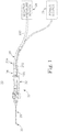
- FIG. 1 A surgical system 20 in accordance with aspects of the present disclosure for use in debriding a brain tumor as part of brain surgery is shown in FIG. 1 .
- the system 20 includes a surgical cutting instrument 22, a source of negative pressure 24, and a power source 26. Details on the various components are provided below.
- the surgical instrument 22 includes a blade assembly 28 forming a cutting implement 30 (referenced generally), a handpiece 32, and an aspiration control device 34.
- the source of negative pressure 24 is fluidly connected to the cutting implement 30 via a fluid pathway 36 extending through the handpiece 32.
- the aspiration control device 34 is also fluidly connected to the fluid pathway 36.
- the power source 26 is electrically connected to a motor (not shown) maintained by the handpiece 32.
- the cutting implement 30 is deployed to a target site, with the user manipulating the handpiece 32 to achieve a desired position of the cutting implement 30 relative to the brain tumor.
- the power source 26 energizes the motor to effectuate a tumor cutting operation at the cutting implement 30.
- the aspiration control device 34 is manually operated by the user to selectively effectuate aspiration at the cutting implement 30 via a vacuum generated by the source of negative pressure 24. In some configurations, the aspiration control device 34 affords the user the ability to vary the rate or level of aspiration, as well as an aggressiveness of cutting at the cutting implement 30.
- the surgical instrument 22 includes the blade assembly 28, the handpiece 32, and the aspiration control device 34 as mentioned above.
- the surgical instrument 22 includes an optional control assembly 40 (referenced generally) configured to provide user control over a rotational position of a component of the blade assembly 28 as described below.
- the blade assembly 28 can assume a variety of forms, and in some configurations includes an outer member assembly 50 having an outer member 52, and an inner member assembly 54 having an inner member 56.
- the inner member 56 is rotatably disposed within the outer member 52, with other components of the assemblies 50, 54 effectuating connection to the handpiece 32.
- the outer and inner members 52, 56 extend distally from the handpiece 32, and combine to form the cutting implement 30 as described below.
- the blade assembly 28 is shown as including two of the members 52, 56, in other configurations, three or more coaxially assembled members can be provided.
- the blade assembly 28, and in particular the members 52, 56 can have a linear or straight configuration as shown, or can alternately have a curved construction (such as by the inclusion of a curved member encompassing at least a portion of the outer member 52).
- the outer member assembly 50 includes an outer member hub 60, a collet 62, and an optional irrigation hub 64.
- the outer member 52 is secured to the outer member hub 60, with the collet 62 facilitating attachment to the handpiece 32.
- the irrigation hub 64 facilitates delivery of an irrigation fluid to the outer member 52.
- the outer member 52 is tubular in some embodiments, and forms a distal region 66.
- the distal region 66 forms in some configurations a cutting window 70 and an elevator tip 72 distal the cutting window 70.
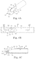
- the distal region 66 can be an integrally formed component of the outer member 52, or can be separately formed and assembled to other components (e.g., the distal region 66 can be formed and then attached to an appropriately sized, rigid metal tube in completing the outer member 52). Regardless, one construction of the distal region 66 in accordance with principles of the present disclosure is shown in greater detail in FIGS. 4A-4C . As best shown in FIG. 4C , the distal region 66 forms a lumen 74 that is otherwise open at the cutting window 70 (and continues proximally through at least a substantial portion of a remainder of the outer member 52 ( FIG. 3 )). With this mind, the cutting window 70 is defined by a cutting window wall 76.
- a recessed portion 78 is formed in the distal region 66 about at least a proximal portion of the cutting window wall 76, such that the distal region 66 tapers in wall thickness along the recessed portion 78.
- the cutting window 70 can have a tear drop-like shape in longitudinal length, decreasing in lateral perimeter width from a distal segment 80 to a proximal segment 82.
- the elevator tip 72 extends distal the cutting window 70, terminating at a sharpened or blade edge 84.
- the elevator tip 72 is closed relative to the lumen 74 and is defined by opposing, first and second surfaces 90, 92.
- the first surface 90 can be designated as an upper surface, and is contiguous with a surface 94 of the distal region 66 at which the cutting window 70 is otherwise defined.
- the second surface 92 serves as a bottom surface.
- the first surface 90 has a scoop-like shape, defining a concave curvature in extension from the cutting window 70 to the blade edge 84.
- the second surface 92 is generally defined by a proximal portion 100 and a distal portion 102. As best shown in FIG. 4C , the proximal portion 100 extends in a linear fashion (in longitudinal cross-section) relative to the cutting window 70. The distal portion 102, however, has a convex curvature in extension from the proximal portion 100 to the blade edge 84. In some embodiments, a continuous curvature is defined by the first surface 90 and the distal portion 102 of the second surface 92, with the continuously curved surfaces meeting at the blade edge 84. In addition to being sharp, the blade edge 84 is located at or below an angled cut defined by the cutting window wall 76. That is to say, FIG.
- the cutting window wall 76/recessed portion 78 forms an angle ⁇ relative to the surface 94, with the cutting window wall 76 tapering in height along the angle ⁇ from the proximal segment 82 to the distal segment 80.
- the blade edge 84 intersects or is "below" an imaginary line defined by the angle ⁇ . It has been surprisingly found that the resultant configuration is well-suited for surgical brain tumor removal procedures. Alternatively, however, other constructions may alternatively be employed.
- distal extension of the elevator tip 72 from the cutting window 70 is characterized by the distal region 66 exhibiting an increase in transverse width. More particularly, and as best shown in FIG. 4B , the distal region 66 (as well as at least a majority of the outer member 52 ( FIG. 3 ) proximal the distal region 66) has a transverse width (or diameter) W 1 immediately proximal, and along at least a substantial portion of, the cutting window 70.
- the elevator tip 72 expands in a generally radially outward fashion in distal extension from the cutting window 70, defining a maximum transverse width (or diameter) W 2 . As shown, the maximum width W 2 of the elevator tip 72 is greater than the width W 1 of the distal region 66 proximal the cutting window 70.
- the elevator tip 72 (e.g., curved surfaces, increased width, and the blade edge 84) combine to provide the elevator tip 72 with a curette-like form.
- the elevator tip 72 is highly amenable for interfacing with the delicate tissues encountered during brain surgery.
- the blade edge 84 promotes partial separation or isolation of tumor from brain and other normal tissue, with the curved surfaces 90, 92 assisting in isolating or separating the tumor from other tissue.
- the elevator tip 72 can be eliminated.
- the distal region 66 can terminate at the cutting window 70 that is otherwise axially and radially open to the lumen 74.
- the cutting window 70 can be formed in the distal region 66 as a side (or radial) window, with the outer member 52 having a relatively uniform outer diameter distal the cutting window 70.
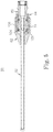
- FIG. 5 Final construction of the outer member assembly 50 is shown in FIG. 5 .
- the outer member 52 is assembled to the outer member hub 60 that in turn is received within the irrigation hub 64.
- seals 104 e.g., O-rings
- an irrigation liquid (not shown) can be delivered to the lumen 74 of the outer member 52 via a sealed gap 106 between the hubs 60, 64 and a bore 108 formed in the outer member 52.
- the assembled hubs 60, 64 are coaxially received with the collet 62, with the outer member 52 extending distal the collet 62 as shown.
- Other constructions capable of effectuating flow of irrigation liquid to the outer member 52 are also envisioned; in yet other configurations, the irrigation hub 64 (as well as any other irrigation component) can be eliminated.
- the inner member assembly 54 includes the inner member 56, as well as an inner member hub 110.
- the inner member hub 110 maintains the inner member 56, and facilitates connection of the inner member assembly 54 to a motor (not shown).
- the inner member hub 110 can assume a variety of forms.
- the inner member 56 is tubular, forming a distal cutting tip 112.
- the cutting tip 112 can include a series of serrations or teeth 114. With this but one acceptable configuration, the teeth 114 are formed about an aperture 116 that is otherwise open to a lumen 118 defined by the inner member 56.
- the aperture 116 and the lumen 118 serve as an aspiration outlet of the aspiration fluid pathway 36 ( FIG. 1 ) otherwise employed for aspirating a target site.
- the cutting tip 112 can assume other forms that may or may not include an aperture fluidly connected to a lumen.
- the cutting tip 112 can be a closed burr.
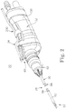
- FIG. 7 Final construction of the blade assembly 28 is shown in FIG. 7 .
- the inner member 56 is received within the lumen 74 ( FIG. 4C ) of the outer member 52, and is attached to the inner member hub 110.
- the inner member hub 110 is positioned proximal the outer member hub 60 and is rotatable relative thereto, such that rotation of the inner member hub 110 effectuates rotation of the inner member 56 relative to the outer member 52.
- the cutting tip 112 of the inner member 56 is positioned at the cutting window 70 of the outer member 52.
- the cutting tip 112 is exteriorly exposed via the cutting window 70 for performing a cutting or debriding procedure.
- the distal region 66 of the outer member 52 e.g., the cutting window 70 and the elevator tip 72
- Aspiration is effectuated at the cutting implement 30 via the aperture 116 provided with the inner member 56 (with the aperture 116 being exteriorly open through the cutting window 70).
- aspiration or suctioning at the cutting implement 30 can be provided by the outer member 52, a separate tubing carried by the cutting implement 30, etc.
- irrigation is provided at the cutting implement via the outer member 52/cutting window 70, although in other embodiments, an additional irrigation supply tube (carried with or separate from the cutting implement 30) can be provided.
- the handpiece 32 can assume a variety of forms that promote manipulation of the blade assembly 28/cutting implement 30 by a user, as well as powered movement of the inner member 56 relative to the outer member 52.
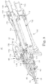
- FIG. 8 illustrates one construction of the handpiece 32 in accordance with the principles of the present disclosure.
- the aspiration control device 34 FIG. 2
- the handpiece 32 is shown in FIG. 8 as being assembled to a portion of the blade assembly 28.
- the handpiece 32 includes a housing 130, the control assembly 40, a motor 132 (shown schematically in FIG. 8 ), and a drive coupling 134.
- the motor 132 is secured within the housing 130, with the housing 130 forming a conduit 138 through which wiring (not shown) otherwise providing power to the motor 132 can extend. Further, the housing 130 preferably forms or includes an aspiration port 140 for fluidly connecting the blade assembly 28 to the source of negative pressure 24 ( FIG. 1 ) as described below.
- the drive coupling 134 mechanically connects the motor 132 to the inner member hub 110, and thus the inner member 56. To this end, a wide variety of constructions can be employed. With some configurations, however, the drive coupling 134 includes an output shaft 150 rotatably linked (e.g., geared) to a drive shaft 152 of the motor 132.
- the output shaft 150 can assume various forms, and with some constructions forms a passage 154 that, upon final assembly, fluidly connects the aspiration port 140 with a passageway 156 formed by the inner member hub 110 (and thus with the lumen 118 of the inner member 56 otherwise assembled within the passageway 156).
- Optional dynamic seals 158 can be included to better ensure a fluid-tight seal between the passage 154 and the aspiration port 140.
- the optional control assembly 40 facilitates rotation of the outer member 52 relative to the inner member 56 as described below, and can assume a variety of forms.
- the control assembly 40 includes an actuator 170 and a translation mechanism 172.
- the actuator 170 can be akin to a wheel, and is rotatably assembled to the housing 130.
- the translation mechanism 172 is configured to translate rotation of the actuator 170 to the outer member hub 60, and thus the outer member 52.
- the translation mechanism 172 includes a post 174 connected to and extending from the actuator 170.
- an end 176 of the post 174 opposite the actuator 170 is adapted to interface with an engagement feature 178 of the outer member hub 60.
- the engagement feature 178 of the outer member hub 60 is a series of circumferentially disposed indentations 180.
- the post end 176 is configured to interface with the indentations 180, akin to a ball and detent relationship.
- rotation of the outer member hub 60 results in rotation of the outer member 52 relative to the inner member 56.
- rotation of the outer member 52 can be achieved by a user without overt movement of the housing 130. The user, while grasping the housing 130 in his or her hand, the surgeon simply rotates the actuator 170 with a finger (or thumb) of the same hand that is otherwise holding the housing 130.
- the control assembly 40 can assume a variety of other forms apart from the description provided above, for example as described in U.S. Patent Application Serial No. 10/854,020 filed September 22, 2004 , published as US 2005/0277970 , and entitled "Surgical Cutting Instrument".
- the control assembly 40 is omitted (i.e., the outer member 52 cannot be independently rotated relative to the inner member 54).
- rotation of the outer member 52 relative to the inner member 56 allows the user to selectively shield the cutting tip 112 from unintentionally contacting, and thus possibly damaging, delicate tissue of the brain and surrounding anatomy during a brain tumor debridement procedure. For example, as shown in FIG.
- a rotational position of the outer member 52 relative to the inner member 56 can be selected such that the cutting tip 112 is exteriorly exposed at the cutting window 70. With this orientation, the cutting tip 112 can contact and cut tissue adjacent the cutting implement 30. Conversely, the outer member 52 can be rotated relative to the inner member 56 such that the cutting tip 112 is within the outer member 52, as shown in FIG. 9B . With this arrangement, then, the outer member 52 prevents the cutting tip 112 from contacting, and possibly damaging, tissue.
- the outer member 52 can be rotated to position or "face" the cutting window 70 at a desired location (e.g., a brain tumor) without movement of the handpiece 32 ( FIG. 8 ) via the control assembly 40 ( FIG. 8 ). That is to say, once the cutting implement 30 is delivered to a target site, the precise location at which cutting will occur (i.e., the cutting window 70) can be controlled by movement of the actuator 170 ( FIG. 8 ); the surgeon is not required to contort his or her hand(s) to achieve a desired point of cutting/position of the cutting window 70.
- a desired location e.g., a brain tumor
- the aspiration control device 34 can assume a variety of forms, and includes a tube 200 assembled to the housing 130 of the handpiece 32.
- the tube 200 along with other components of the aspiration control device 34 in accordance with some aspects of the present disclosure is shown in FIG. 10 .
- the aspiration control device 34 can include a clip 202 and a connector assembly 204.
- the clip 202 connects the tube 200 to the handpiece 32 ( FIG. 2 ).
- the connector assembly 204 fluidly connects the tube 200 to the fluid pathway 36 ( FIG. 1 ) established with the source of negative pressure 24 ( FIG. 1 ).
- the tube 200 has a shape commensurate with a contour of a surface of the housing 130 ( FIG. 2 ) to which the tube 200 is assembled, and thus may form one or more bends. Regardless, the tube 200 forms a lumen (not shown) extending from a closed, first end 206 to an open, second end 208. Further, the tube 200 forms a user interface hole 210 adjacent the first end 206 that is otherwise fluidly open to the lumen.
- One construction of the user interface hole 210 is shown in FIG. 11 , and is generally sized and shaped to interface with (i.e., be selectively covered by), a user's finger.
- a perimeter 212 of the user interface hole 210 has a tear drop-like shape, having a relatively linear first segment 214 and an enlarged, rounded second segment 216.
- This shape generally coincides with a natural shape of an adult's fingertip, although other shapes are also acceptable.
- control over the aspiration delivered at the cutting implement 30 is selectively effectuated by covering or uncovering the user interface hole 210.
- the clip 202 can assume a variety of forms adapted to connect the tube 200 to the housing 130 ( FIG. 2 ).
- the tube 200 can be permanently affixed to, or formed by (e.g., as an internal bore), the handpiece 32 ( FIG. 2 ), such that the clip 202 can be eliminated.
- the connector assembly 204 can also assume a variety of forms, and with some constructions includes a tee connector 220 and a connection block 222.
- the tee connector 220 is configured for establishing fluid connection with tubing (not shown) between the handpiece 32 ( FIG. 1 ) and the source of negative pressure 24 ( FIG. 1 ).
- the connection block 222 is configured for attachment to the second end 208 of the tube 200, as well as to the tee connector 220.
- the connector assembly 204 fluidly connects the lumen (not shown) of the tube 200 with the fluid pathway 36 ( FIG. 1 ).
- a wide variety of other constructions for the connector assembly 204 are equally acceptable.
- final assembly of the system 20 includes a first tubing 230 extending between, and fluidly connecting, the source of negative pressure 24 and the connector assembly 204.
- a second tubing 232 fluidly connects the connector assembly 204 with the aspiration port 140 of the handpiece 32.
- the fluid pathway 36 is established form the source of negative pressure 24 to the cutting implement 30.
- the source of negative pressure 24 is fluidly connected to the aspiration port 140 via the first tubing 230, the connector assembly 204, and the second tubing 232.
- the aspiration port 140 is fluidly connected to the blade assembly 28 via the passage 154 ( FIG. 8 ) of the output shaft 150 ( FIG. 8 ).
- the fluid pathway 36 further extends through the lumen 118 ( FIG. 6 ) of the inner member 56 ( FIG. 6 ), and is open at the aperture 116 ( FIG. 6 ).
- the aspiration outlet at the cutting implement 30 can be provided in other forms that may or may not include the aperture 116 of the inner member 56 (e.g., aspiration can be provided via the outer member 52, via a separate tube provided with the blade assembly 28, etc.).
- the tube 200 of the aspiration control device 34 is also in fluid communication with the fluid pathway 36 via the connector assembly 204 with the user interface hole 210 being open to ambient.
- the aspiration control device 34 affords the user the ability to control a level of vacuum applied at the cutting implement 30, for example by selectively covering or uncovering the user interface hole 210 ( FIG. 11 ).
- a level or rate or vacuum delivered to or experienced at the aperture 116 ( FIG. 6 ), or other aspiration outlet format, will increase as the user interface hole 210 ( FIG. 11 ) is increasingly covered, and vice-versa.
- the user interface hole 210 has, in some configurations, a larger surface area as compared to the aspiration outlet provided at the cutting implement 30 through which suctioning is otherwise applied.
- the aspiration outlet provided with the cutting implement 30 is the aperture 116 formed by the inner member 56 ( FIG. 3 ).
- a size of the user interface hole 210 can be selected to be greater than a size of the aperture 116.
- a vacuum level at the cutting implement 30 is substantially zero in that the user interface hole 210 provides a path of least resistance for negative pressure within the fluid pathway 36.
- a user will readily "sense" vacuum or suction at the user interface hole 210, and is thus provided with direct, tactile feedback as to a level of vacuum being applied at the cutting implement 30.
- the user interface hole 210 affords essentially infinite control over the applied vacuum (between zero and maximum generated at the source of negative pressure 24) due to the absence of preestablished indexes or other stop mechanism along the aspiration control device 34.
- treatment of a brain tumor 250 in accordance with aspects of the present disclosure includes forming an access opening in the patient's skull 252 (e.g., a conventional craniotomy).
- FIG. 12A schematically illustrates other anatomy, including the dura 254, the arachnoid 256, the pia 258, and the cortex 260.
- the brain tumor 250 is shown as projecting from a natural anatomy of the cortex 260, exteriorly "covered” by the pia 258.
- the brain tumor 250 may be internal or embedded within the cortex (or other brain tissue) 260. Regardless, once a target site 262 at which the brain tumor 250 is located has been exposed, the system 20 is operated to remove at least some, preferably all, of the brain tumor 250.
- the cutting implement 30 is deployed to the target site 262.
- the power supply 26 is inactive, such that the inner member 56 ( FIG. 3 ) does not move relative to the outer member 52.
- the source of negative pressure 24 may or may not be activated during initial placement of the cutting implement 30. That is to say, a negative pressure condition may or may not be established along the fluid pathway 36. Where the source of negative pressure 24 is activated, however, the user manually effectuates control over delivery of negative pressure to the cutting implement 30, such as by leaving the user interface hole 210 ( FIG. 11 ) associated with the aspiration control device 34 uncovered.
- this arrangement causes virtually all of the negative pressure generated by the source of negative pressure 24 to be delivered to the user interface hole 210, and thus not the aspiration outlet/aperture 116 of the cutting implement in a manner that might otherwise negatively impact surrounding tissue of the target site 262.
- the surgeon manipulates the handpiece 32 so as to position the elevator tip 72 (where provided) partially between the brain tumor 250 and surrounding tissue of the target site 262.
- the control assembly 40 can be operated by the surgeon to rotate the elevator tip 72 to a desired spatial orientation relative to the target site 262 without overt twisting/contortion of the surgeon's hand(s).
- the elevator tip 72 is positioned between the brain tumor 250 and a portion of the pia mater 258.
- the elevator tip 72 partially isolating the brain tumor 250 from this tissue.
- the elevator tip 72 at least partially separates or isolates the brain tumor 250 from the surrounding tissue with the blade edge 84 possibly partially severing a portion of the brain tumor 250 away from the surrounding tissue.
- the blade edge 84 can be manipulated to pierce the pia 258 at a relatively precise location in close proximity to the tumor 250. Further, by controlling (minimizing) aspiration at the cutting implement, unnecessary damage to the pia 258 (and other tissue) is avoided.
- the handpiece 32 can be further manipulated to cause the elevator tip 72 to pry the brain tumor 250 away from the surrounding tissue.
- the cutting tip 112 (referenced generally in FIG. 12B ) is placed into contact with the brain tumor 250.
- the outer member 52 is moved (e.g., rotated) such that the cutting window 70 "faces" the brain tumor 250.
- the aspiration control device 34 is manually operated to effectuate delivery of negative pressure to the cutting implement 30, thus drawing or suctioning the brain tumor 250 into contact with the cutting tip 112.
- the surgeon can at least partially obstruct the user interface hole 210 ( FIG. 11 ), effectuating a more complete fluid connection between the source of negative pressure 24 and the aspiration aperture 116.
- the surgeon can readily, visually confirm desired placement and orientation of the cutting implement 30, and in particular the elevator tip 72 and the cutting window 70/cutting tip 112, relative to the brain tumor 250 and the surrounding tissue.
- the power supply 26 is activated, thus causing the inner member 56 ( FIG. 3 ) to move relative to the outer member 52.
- This action causes the cutting tip 112 to move within the cutting window 70, cutting or debriding the contacted brain tumor 250.
- the motor 132 FIG. 8
- the aspiration control device 34 can be manually operated (e.g., movement of the surgeon's finger relative to the hole 210) to effectuate an increased vacuum level at the cutting implement 30, thus removing debrided brain tumor tissue from the target site 262.
- the surgeon can periodically confirm continued desired positioning of the cutting implement 30 relative to the brain tumor 250 and the surrounding tissue 256.
- the outer member 52 can be rotated relative to the inner member 56 ( FIG. 3 ), thereby altering a spatial position of the cutting window 70, and thus a point of contact of the cutting tip 112 with the brain tumor 250.
- the actuator 170 FIG. 8
- the level of vacuum or rate of aspiration can be manually changed at any time by the surgeon, for example by simply covering more or less of the hole 210 ( FIG. 11 ).
- the surgical systems and methods of the present disclosure provide a marked improvement over previous brain tumor surgical techniques.
- the cutting implement including the cutting tip and optional elevator tip, can safely remove selected brain tumor tissue, but not damage the surrounding tissues. Further, with selective variable aspiration, the brain tumor tissue can be isolated from the surrounding tissue for subsequent removal and more aggressive cutting. Further, the ability to rotate the outer member assists in protecting the delicate brain anatomy tissue (e.g., dura, arachnoid, pia, etc.).
Landscapes
- Health & Medical Sciences (AREA)
- Surgery (AREA)
- Life Sciences & Earth Sciences (AREA)
- Biomedical Technology (AREA)
- Nuclear Medicine, Radiotherapy & Molecular Imaging (AREA)
- Engineering & Computer Science (AREA)
- Orthopedic Medicine & Surgery (AREA)
- Heart & Thoracic Surgery (AREA)
- Medical Informatics (AREA)
- Molecular Biology (AREA)
- Animal Behavior & Ethology (AREA)
- General Health & Medical Sciences (AREA)
- Public Health (AREA)
- Veterinary Medicine (AREA)
- Surgical Instruments (AREA)
Applications Claiming Priority (2)
| Application Number | Priority Date | Filing Date | Title |
|---|---|---|---|
| US11/938,625 US8906053B2 (en) | 2007-11-12 | 2007-11-12 | Systems and methods for surgical removal of brain tumors |
| PCT/US2008/082958 WO2009064688A2 (en) | 2007-11-12 | 2008-11-10 | Systems and methods for surgical removal of brain tumors |
Publications (2)
| Publication Number | Publication Date |
|---|---|
| EP2227154A2 EP2227154A2 (en) | 2010-09-15 |
| EP2227154B1 true EP2227154B1 (en) | 2017-03-29 |
Family
ID=40291000
Family Applications (1)
| Application Number | Title | Priority Date | Filing Date |
|---|---|---|---|
| EP08849776.3A Not-in-force EP2227154B1 (en) | 2007-11-12 | 2008-11-10 | Systems and methods for surgical removal of brain tumors |
Country Status (7)
Cited By (1)
| Publication number | Priority date | Publication date | Assignee | Title |
|---|---|---|---|---|
| WO2022155049A1 (en) * | 2021-01-12 | 2022-07-21 | Arthrex, Inc. | Surgical cutting tool |
Families Citing this family (41)
| Publication number | Priority date | Publication date | Assignee | Title |
|---|---|---|---|---|
| US20080121343A1 (en) | 2003-12-31 | 2008-05-29 | Microfabrica Inc. | Electrochemical Fabrication Methods Incorporating Dielectric Materials and/or Using Dielectric Substrates |
| US20090270894A1 (en) * | 2008-04-25 | 2009-10-29 | Joshua David Rubin | Surgical instrument with internal irrigation |
| EP2326266B1 (en) * | 2008-06-23 | 2018-05-16 | Microfabrica Inc. | Miniature shredding tool for medical applications |
| US10939934B2 (en) | 2008-06-23 | 2021-03-09 | Microfabrica Inc. | Miniature shredding tools for use in medical applications, methods for making, and procedures for using |
| US9451977B2 (en) | 2008-06-23 | 2016-09-27 | Microfabrica Inc. | MEMS micro debrider devices and methods of tissue removal |
| US9814484B2 (en) | 2012-11-29 | 2017-11-14 | Microfabrica Inc. | Micro debrider devices and methods of tissue removal |
| US8795278B2 (en) | 2008-06-23 | 2014-08-05 | Microfabrica Inc. | Selective tissue removal tool for use in medical applications and methods for making and using |
| US9504247B2 (en) | 2008-12-16 | 2016-11-29 | Nico Corporation | System for collecting and preserving tissue cores |
| US9216031B2 (en) | 2008-12-16 | 2015-12-22 | Nico Corporation | Tissue removal device with adjustable fluid supply sleeve for neurosurgical and spinal surgery applications |
| US9655639B2 (en) * | 2008-12-16 | 2017-05-23 | Nico Corporation | Tissue removal device for use with imaging devices in neurosurgical and spinal surgery applications |
| US8357175B2 (en) * | 2008-12-16 | 2013-01-22 | Nico Corporation | Positioning system for tissue removal device |
| US20100152762A1 (en) * | 2008-12-16 | 2010-06-17 | Mark Joseph L | Tissue removal system with multi-directional foot actuator assembly for neurosurgical and spinal surgery applications |
| US8496599B2 (en) * | 2008-12-16 | 2013-07-30 | Nico Corporation | Tissue removal device for neurosurgical and spinal surgery applications |
| US9931105B2 (en) | 2008-12-16 | 2018-04-03 | Nico Corporation | System and method of taking and collecting tissue cores for treatment |
| US8460327B2 (en) * | 2008-12-16 | 2013-06-11 | Nico Corporation | Tissue removal device for neurosurgical and spinal surgery applications |
| US8430825B2 (en) * | 2008-12-16 | 2013-04-30 | Nico Corporation | Tissue removal device for neurosurgical and spinal surgery applications |
| US10080578B2 (en) | 2008-12-16 | 2018-09-25 | Nico Corporation | Tissue removal device with adjustable delivery sleeve for neurosurgical and spinal surgery applications |
| US9820480B2 (en) | 2008-12-16 | 2017-11-21 | Nico Corporation | System for collecting and preserving tissue cores |
| US9279751B2 (en) | 2008-12-16 | 2016-03-08 | Nico Corporation | System and method of taking and collecting tissue cores for treatment |
| US8657841B2 (en) | 2008-12-16 | 2014-02-25 | Nico Corporation | Tissue removal device for neurosurgical and spinal surgery applications |
| US8702738B2 (en) * | 2008-12-16 | 2014-04-22 | Nico Corporation | Tissue removal device for neurosurgical and spinal surgery applications |
| US10368890B2 (en) | 2008-12-16 | 2019-08-06 | Nico Corporation | Multi-functional surgical device for neurosurgical and spinal surgery applications |
| RU2414862C1 (ru) * | 2009-07-29 | 2011-03-27 | Федеральное Государственное учреждение Российский научно-исследовательский нейрохирургический институт им. Проф. А.Л. Поленова | Способ хирургического лечения рецидива опухоли больших полушарий у больных с декомпрессивной краниотомией |
| US8465471B2 (en) | 2009-08-05 | 2013-06-18 | Rocin Laboratories, Inc. | Endoscopically-guided electro-cauterizing power-assisted fat aspiration system for aspirating visceral fat tissue within the abdomen of a patient |
| US8348929B2 (en) | 2009-08-05 | 2013-01-08 | Rocin Laboratories, Inc. | Endoscopically-guided tissue aspiration system for safely removing fat tissue from a patient |
| US20140148729A1 (en) | 2012-11-29 | 2014-05-29 | Gregory P. Schmitz | Micro-mechanical devices and methods for brain tumor removal |
| EP2467072B1 (en) | 2009-08-18 | 2016-12-14 | Microfabrica Inc. | Concentric cutting devices for use in minimally invasive medical procedures |
| US20130158578A1 (en) * | 2010-09-03 | 2013-06-20 | University Of Washington | Neurosurgical devices and associated systems and methods |
| US9186166B2 (en) | 2011-09-01 | 2015-11-17 | Depuy Mitek, Llc | Tissue shavers |
| US10342564B2 (en) | 2012-09-27 | 2019-07-09 | Nico Corporation | Variable aspiration control device |
| US9445831B2 (en) | 2012-09-27 | 2016-09-20 | Nico Corporation | Variable aspiration control device |
| EP3022064A4 (en) | 2013-07-16 | 2017-06-07 | Microfabrica Inc. | Counterfeiting deterent and security devices systems and methods |
| EP3131479B1 (en) | 2014-04-17 | 2019-04-10 | Stryker Corporation | Surgical tool with selectively bendable shaft that resists buckling |
| US20170042528A1 (en) | 2014-04-24 | 2017-02-16 | Dilantha B. ELLEGALA | Modified ultrasound aspirator for use in and around vital structures of a body |
| US20160066945A1 (en) * | 2014-09-08 | 2016-03-10 | Medtronic-Xomed, Inc. | Tumor margin device |
| CN109475366B (zh) | 2016-07-14 | 2021-12-28 | 史赛克欧洲运营有限责任公司 | 具有阻塞减少梢端的外科手术器械的切割组件 |
| US10716590B2 (en) * | 2017-03-20 | 2020-07-21 | Penumbra, Inc. | Methods and apparatus for removal of intracranial hemorrhage |
| CA3070544A1 (en) | 2017-07-25 | 2019-01-31 | Stryker European Holdings I, Llc | Irrigation sleeves for use with surgical systems |
| JP7244656B2 (ja) * | 2019-01-15 | 2023-03-22 | ボストン サイエンティフィック リミテッド | 供給ラインフィットメントを備えたアテレクトミーシステム |
| WO2022094228A1 (en) | 2020-10-30 | 2022-05-05 | Boston Scientific Scimed, Inc. | Atherectomy burrs with blood flow enhancements |
| RU2764831C1 (ru) * | 2021-04-26 | 2022-01-21 | Федеральное государственное бюджетное учреждение "Новосибирский научно-исследовательский институт травматологии и ортопедии им. Я.Л. Цивьяна" Министерства здравоохранения Российской Федерации (ФГБУ "ННИИТО им. Я.Л. Цивьяна" Минздрава России) | Способ удаления церебральной менингиомы |
Family Cites Families (31)
| Publication number | Priority date | Publication date | Assignee | Title |
|---|---|---|---|---|
| US3055370A (en) * | 1958-11-28 | 1962-09-25 | William W Mckinney | Pallidotomy surgical instrument |
| US4517977A (en) * | 1981-07-24 | 1985-05-21 | Unisearch Limited | Co-axial tube surgical infusion/suction cutter tip |
| US5403307A (en) * | 1987-05-01 | 1995-04-04 | Zelman; Jerry | Apparatus, system, and method for softening and extracting cataractous tissue |
| GB8822492D0 (en) * | 1988-09-24 | 1988-10-26 | Considine J | Apparatus for removing tumours from hollow organs of body |
| US5269785A (en) * | 1990-06-28 | 1993-12-14 | Bonutti Peter M | Apparatus and method for tissue removal |
| US5268785A (en) * | 1993-02-08 | 1993-12-07 | The United States Of America As Represented By The Secretary Of The Army | All-optical switch utilizing inversion of two-level systems |
| US5403276A (en) * | 1993-02-16 | 1995-04-04 | Danek Medical, Inc. | Apparatus for minimally invasive tissue removal |
| US5643304A (en) * | 1993-02-16 | 1997-07-01 | Danek Medical, Inc. | Method and apparatus for minimally invasive tissue removal |
| US5492527A (en) * | 1994-09-09 | 1996-02-20 | Linvatec Corporation | Arthroscopic shaver with rotatable collet and slide aspiration control valve |
| US5694591A (en) * | 1995-05-02 | 1997-12-02 | Hewlett Packard Company | Reducing query response time using tree balancing |
| US5709698A (en) * | 1996-02-26 | 1998-01-20 | Linvatec Corporation | Irrigating/aspirating shaver blade assembly |
| US5722985A (en) * | 1996-12-27 | 1998-03-03 | Pettus; William G. | Instrument for tumor therapy |
| US5849023A (en) * | 1996-12-27 | 1998-12-15 | Mericle; Robert William | Disposable remote flexible drive cutting apparatus |
| US6156049A (en) * | 1997-04-11 | 2000-12-05 | Coherent Inc. | Method and apparatus for transurethral resection of the prostate |
| US6024751A (en) * | 1997-04-11 | 2000-02-15 | Coherent Inc. | Method and apparatus for transurethral resection of the prostate |
| US6428498B2 (en) * | 1998-04-14 | 2002-08-06 | Renan Uflacker | Suction catheter for rapidly debriding abscesses |
| EP1029509A1 (de) | 1999-02-19 | 2000-08-23 | Magnetic Vision GmbH | Vorrichtung zum Schneiden und/oder Absaugen von Gewebeteilen oder dgl. |
| US6312441B1 (en) * | 1999-03-04 | 2001-11-06 | Stryker Corporation | Powered handpiece for performing endoscopic surgical procedures |
| JP2000300573A (ja) * | 1999-04-19 | 2000-10-31 | Sumitomo Bakelite Co Ltd | 手術用吸引具 |
| US6436067B1 (en) * | 1999-12-03 | 2002-08-20 | Stryker Corporation | Powered surgical handpiece with suction conduit including a stepped valve to regulate flow through the suction conduit |
| JP3596807B2 (ja) * | 2000-08-09 | 2004-12-02 | インターナショナル・ビジネス・マシーンズ・コーポレーション | プリント配線板及びその製造方法 |
| US6503263B2 (en) * | 2000-09-24 | 2003-01-07 | Medtronic, Inc. | Surgical micro-shaving instrument with elevator tip |
| US20020099410A1 (en) * | 2001-01-11 | 2002-07-25 | Bio-Seal Tech Inc. | Device and method for sealing a puncture in a blood vessel |
| WO2002089722A1 (en) * | 2001-04-27 | 2002-11-14 | Nagashima Medical Instruments Co., Ltd | Medical rinsing and sucking device |
| DE20117907U1 (de) | 2001-11-02 | 2002-01-10 | Select Medizin-Technik Hermann Sutter GmbH, 79108 Freiburg | Koagulationsinstrument mit einem Saugkanal |
| US20030107814A1 (en) * | 2001-12-11 | 2003-06-12 | Altmann Griffith E. | Method and apparatus for improving the dynamic range and accuracy of a Shack-Hartmann wavefront sensor |
| US7682333B2 (en) * | 2002-01-15 | 2010-03-23 | Stryker Corporation | Powered surgical handpiece with precision suction control |
| US7247161B2 (en) * | 2002-03-22 | 2007-07-24 | Gyrus Ent L.L.C. | Powered surgical apparatus, method of manufacturing powered surgical apparatus, and method of using powered surgical apparatus |
| US20040092992A1 (en) * | 2002-10-23 | 2004-05-13 | Kenneth Adams | Disposable battery powered rotary tissue cutting instruments and methods therefor |
| US7785337B2 (en) | 2003-09-09 | 2010-08-31 | Medtronic Xomed, Inc. | Surgical micro-burring instrument and method of performing sinus surgery |
| US8277474B2 (en) * | 2004-05-26 | 2012-10-02 | Medtronic, Inc. | Surgical cutting instrument |
-
2007
- 2007-11-12 US US11/938,625 patent/US8906053B2/en active Active
-
2008
- 2008-11-10 AU AU2008321166A patent/AU2008321166B2/en not_active Ceased
- 2008-11-10 ES ES08849776.3T patent/ES2628186T3/es active Active
- 2008-11-10 JP JP2010534114A patent/JP5452499B2/ja not_active Expired - Fee Related
- 2008-11-10 WO PCT/US2008/082958 patent/WO2009064688A2/en active Application Filing
- 2008-11-10 EP EP08849776.3A patent/EP2227154B1/en not_active Not-in-force
- 2008-11-10 CA CA2704592A patent/CA2704592C/en active Active
-
2013
- 2013-12-27 JP JP2013271582A patent/JP5848746B2/ja active Active
Non-Patent Citations (1)
| Title |
|---|
| None * |
Cited By (1)
| Publication number | Priority date | Publication date | Assignee | Title |
|---|---|---|---|---|
| WO2022155049A1 (en) * | 2021-01-12 | 2022-07-21 | Arthrex, Inc. | Surgical cutting tool |
Also Published As
| Publication number | Publication date |
|---|---|
| EP2227154A2 (en) | 2010-09-15 |
| CA2704592C (en) | 2013-09-10 |
| ES2628186T3 (es) | 2017-08-02 |
| US20090124975A1 (en) | 2009-05-14 |
| AU2008321166A1 (en) | 2009-05-22 |
| US8906053B2 (en) | 2014-12-09 |
| AU2008321166B2 (en) | 2016-05-19 |
| JP5848746B2 (ja) | 2016-01-27 |
| WO2009064688A3 (en) | 2009-07-23 |
| WO2009064688A2 (en) | 2009-05-22 |
| JP2011502709A (ja) | 2011-01-27 |
| JP2014138846A (ja) | 2014-07-31 |
| CA2704592A1 (en) | 2009-05-22 |
| JP5452499B2 (ja) | 2014-03-26 |
Similar Documents
| Publication | Publication Date | Title |
|---|---|---|
| EP2227154B1 (en) | Systems and methods for surgical removal of brain tumors | |
| EP2391284B1 (en) | Systems and methods for surgical removal of brain tumors | |
| EP2262432B1 (en) | Systems for surgical removal of tissue | |
| US20190254695A1 (en) | Tumor margin device |
Legal Events
| Date | Code | Title | Description |
|---|---|---|---|
| PUAI | Public reference made under article 153(3) epc to a published international application that has entered the european phase |
Free format text: ORIGINAL CODE: 0009012 |
|
| 17P | Request for examination filed |
Effective date: 20100609 |
|
| AK | Designated contracting states |
Kind code of ref document: A2 Designated state(s): AT BE BG CH CY CZ DE DK EE ES FI FR GB GR HR HU IE IS IT LI LT LU LV MC MT NL NO PL PT RO SE SI SK TR |
|
| AX | Request for extension of the european patent |
Extension state: AL BA MK RS |
|
| DAX | Request for extension of the european patent (deleted) | ||
| 17Q | First examination report despatched |
Effective date: 20140103 |
|
| GRAP | Despatch of communication of intention to grant a patent |
Free format text: ORIGINAL CODE: EPIDOSNIGR1 |
|
| INTG | Intention to grant announced |
Effective date: 20161025 |
|
| GRAS | Grant fee paid |
Free format text: ORIGINAL CODE: EPIDOSNIGR3 |
|
| GRAA | (expected) grant |
Free format text: ORIGINAL CODE: 0009210 |
|
| AK | Designated contracting states |
Kind code of ref document: B1 Designated state(s): AT BE BG CH CY CZ DE DK EE ES FI FR GB GR HR HU IE IS IT LI LT LU LV MC MT NL NO PL PT RO SE SI SK TR |
|
| REG | Reference to a national code |
Ref country code: GB Ref legal event code: FG4D |
|
| REG | Reference to a national code |
Ref country code: CH Ref legal event code: EP |
|
| REG | Reference to a national code |
Ref country code: AT Ref legal event code: REF Ref document number: 879016 Country of ref document: AT Kind code of ref document: T Effective date: 20170415 |
|
| REG | Reference to a national code |
Ref country code: IE Ref legal event code: FG4D |
|
| REG | Reference to a national code |
Ref country code: DE Ref legal event code: R096 Ref document number: 602008049520 Country of ref document: DE |
|
| REG | Reference to a national code |
Ref country code: NL Ref legal event code: FP |
|
| PG25 | Lapsed in a contracting state [announced via postgrant information from national office to epo] |
Ref country code: FI Free format text: LAPSE BECAUSE OF FAILURE TO SUBMIT A TRANSLATION OF THE DESCRIPTION OR TO PAY THE FEE WITHIN THE PRESCRIBED TIME-LIMIT Effective date: 20170329 Ref country code: HR Free format text: LAPSE BECAUSE OF FAILURE TO SUBMIT A TRANSLATION OF THE DESCRIPTION OR TO PAY THE FEE WITHIN THE PRESCRIBED TIME-LIMIT Effective date: 20170329 Ref country code: LT Free format text: LAPSE BECAUSE OF FAILURE TO SUBMIT A TRANSLATION OF THE DESCRIPTION OR TO PAY THE FEE WITHIN THE PRESCRIBED TIME-LIMIT Effective date: 20170329 Ref country code: NO Free format text: LAPSE BECAUSE OF FAILURE TO SUBMIT A TRANSLATION OF THE DESCRIPTION OR TO PAY THE FEE WITHIN THE PRESCRIBED TIME-LIMIT Effective date: 20170629 Ref country code: GR Free format text: LAPSE BECAUSE OF FAILURE TO SUBMIT A TRANSLATION OF THE DESCRIPTION OR TO PAY THE FEE WITHIN THE PRESCRIBED TIME-LIMIT Effective date: 20170630 |
|
| REG | Reference to a national code |
Ref country code: ES Ref legal event code: FG2A Ref document number: 2628186 Country of ref document: ES Kind code of ref document: T3 Effective date: 20170802 |
|
| REG | Reference to a national code |
Ref country code: AT Ref legal event code: MK05 Ref document number: 879016 Country of ref document: AT Kind code of ref document: T Effective date: 20170329 |
|
| PG25 | Lapsed in a contracting state [announced via postgrant information from national office to epo] |
Ref country code: BG Free format text: LAPSE BECAUSE OF FAILURE TO SUBMIT A TRANSLATION OF THE DESCRIPTION OR TO PAY THE FEE WITHIN THE PRESCRIBED TIME-LIMIT Effective date: 20170629 Ref country code: SE Free format text: LAPSE BECAUSE OF FAILURE TO SUBMIT A TRANSLATION OF THE DESCRIPTION OR TO PAY THE FEE WITHIN THE PRESCRIBED TIME-LIMIT Effective date: 20170329 Ref country code: LV Free format text: LAPSE BECAUSE OF FAILURE TO SUBMIT A TRANSLATION OF THE DESCRIPTION OR TO PAY THE FEE WITHIN THE PRESCRIBED TIME-LIMIT Effective date: 20170329 |
|
| PG25 | Lapsed in a contracting state [announced via postgrant information from national office to epo] |
Ref country code: CZ Free format text: LAPSE BECAUSE OF FAILURE TO SUBMIT A TRANSLATION OF THE DESCRIPTION OR TO PAY THE FEE WITHIN THE PRESCRIBED TIME-LIMIT Effective date: 20170329 Ref country code: IT Free format text: LAPSE BECAUSE OF FAILURE TO SUBMIT A TRANSLATION OF THE DESCRIPTION OR TO PAY THE FEE WITHIN THE PRESCRIBED TIME-LIMIT Effective date: 20170329 Ref country code: AT Free format text: LAPSE BECAUSE OF FAILURE TO SUBMIT A TRANSLATION OF THE DESCRIPTION OR TO PAY THE FEE WITHIN THE PRESCRIBED TIME-LIMIT Effective date: 20170329 Ref country code: RO Free format text: LAPSE BECAUSE OF FAILURE TO SUBMIT A TRANSLATION OF THE DESCRIPTION OR TO PAY THE FEE WITHIN THE PRESCRIBED TIME-LIMIT Effective date: 20170329 Ref country code: EE Free format text: LAPSE BECAUSE OF FAILURE TO SUBMIT A TRANSLATION OF THE DESCRIPTION OR TO PAY THE FEE WITHIN THE PRESCRIBED TIME-LIMIT Effective date: 20170329 Ref country code: SK Free format text: LAPSE BECAUSE OF FAILURE TO SUBMIT A TRANSLATION OF THE DESCRIPTION OR TO PAY THE FEE WITHIN THE PRESCRIBED TIME-LIMIT Effective date: 20170329 |
|
| REG | Reference to a national code |
Ref country code: FR Ref legal event code: PLFP Year of fee payment: 10 |
|
| PG25 | Lapsed in a contracting state [announced via postgrant information from national office to epo] |
Ref country code: PL Free format text: LAPSE BECAUSE OF FAILURE TO SUBMIT A TRANSLATION OF THE DESCRIPTION OR TO PAY THE FEE WITHIN THE PRESCRIBED TIME-LIMIT Effective date: 20170329 Ref country code: PT Free format text: LAPSE BECAUSE OF FAILURE TO SUBMIT A TRANSLATION OF THE DESCRIPTION OR TO PAY THE FEE WITHIN THE PRESCRIBED TIME-LIMIT Effective date: 20170731 Ref country code: IS Free format text: LAPSE BECAUSE OF FAILURE TO SUBMIT A TRANSLATION OF THE DESCRIPTION OR TO PAY THE FEE WITHIN THE PRESCRIBED TIME-LIMIT Effective date: 20170729 |
|
| REG | Reference to a national code |
Ref country code: DE Ref legal event code: R097 Ref document number: 602008049520 Country of ref document: DE |
|
| PG25 | Lapsed in a contracting state [announced via postgrant information from national office to epo] |
Ref country code: DK Free format text: LAPSE BECAUSE OF FAILURE TO SUBMIT A TRANSLATION OF THE DESCRIPTION OR TO PAY THE FEE WITHIN THE PRESCRIBED TIME-LIMIT Effective date: 20170329 |
|
| PLBE | No opposition filed within time limit |
Free format text: ORIGINAL CODE: 0009261 |
|
| STAA | Information on the status of an ep patent application or granted ep patent |
Free format text: STATUS: NO OPPOSITION FILED WITHIN TIME LIMIT |
|
| 26N | No opposition filed |
Effective date: 20180103 |
|
| PG25 | Lapsed in a contracting state [announced via postgrant information from national office to epo] |
Ref country code: SI Free format text: LAPSE BECAUSE OF FAILURE TO SUBMIT A TRANSLATION OF THE DESCRIPTION OR TO PAY THE FEE WITHIN THE PRESCRIBED TIME-LIMIT Effective date: 20170329 |
|
| PG25 | Lapsed in a contracting state [announced via postgrant information from national office to epo] |
Ref country code: MC Free format text: LAPSE BECAUSE OF FAILURE TO SUBMIT A TRANSLATION OF THE DESCRIPTION OR TO PAY THE FEE WITHIN THE PRESCRIBED TIME-LIMIT Effective date: 20170329 |
|
| PG25 | Lapsed in a contracting state [announced via postgrant information from national office to epo] |
Ref country code: CH Free format text: LAPSE BECAUSE OF NON-PAYMENT OF DUE FEES Effective date: 20171130 Ref country code: LI Free format text: LAPSE BECAUSE OF NON-PAYMENT OF DUE FEES Effective date: 20171130 |
|
| PG25 | Lapsed in a contracting state [announced via postgrant information from national office to epo] |
Ref country code: LU Free format text: LAPSE BECAUSE OF NON-PAYMENT OF DUE FEES Effective date: 20171110 |
|
| REG | Reference to a national code |
Ref country code: BE Ref legal event code: MM Effective date: 20171130 |
|
| REG | Reference to a national code |
Ref country code: IE Ref legal event code: MM4A |
|
| PG25 | Lapsed in a contracting state [announced via postgrant information from national office to epo] |
Ref country code: MT Free format text: LAPSE BECAUSE OF NON-PAYMENT OF DUE FEES Effective date: 20171110 |
|
| REG | Reference to a national code |
Ref country code: FR Ref legal event code: PLFP Year of fee payment: 11 |
|
| PG25 | Lapsed in a contracting state [announced via postgrant information from national office to epo] |
Ref country code: IE Free format text: LAPSE BECAUSE OF NON-PAYMENT OF DUE FEES Effective date: 20171110 |
|
| PG25 | Lapsed in a contracting state [announced via postgrant information from national office to epo] |
Ref country code: BE Free format text: LAPSE BECAUSE OF NON-PAYMENT OF DUE FEES Effective date: 20171130 |
|
| PG25 | Lapsed in a contracting state [announced via postgrant information from national office to epo] |
Ref country code: HU Free format text: LAPSE BECAUSE OF FAILURE TO SUBMIT A TRANSLATION OF THE DESCRIPTION OR TO PAY THE FEE WITHIN THE PRESCRIBED TIME-LIMIT; INVALID AB INITIO Effective date: 20081110 |
|
| PG25 | Lapsed in a contracting state [announced via postgrant information from national office to epo] |
Ref country code: CY Free format text: LAPSE BECAUSE OF NON-PAYMENT OF DUE FEES Effective date: 20170329 |
|
| PG25 | Lapsed in a contracting state [announced via postgrant information from national office to epo] |
Ref country code: TR Free format text: LAPSE BECAUSE OF FAILURE TO SUBMIT A TRANSLATION OF THE DESCRIPTION OR TO PAY THE FEE WITHIN THE PRESCRIBED TIME-LIMIT Effective date: 20170329 |
|
| PGFP | Annual fee paid to national office [announced via postgrant information from national office to epo] |
Ref country code: NL Payment date: 20201029 Year of fee payment: 13 |
|
| PGFP | Annual fee paid to national office [announced via postgrant information from national office to epo] |
Ref country code: ES Payment date: 20211201 Year of fee payment: 14 |
|
| REG | Reference to a national code |
Ref country code: NL Ref legal event code: MM Effective date: 20211201 |
|
| PG25 | Lapsed in a contracting state [announced via postgrant information from national office to epo] |
Ref country code: NL Free format text: LAPSE BECAUSE OF NON-PAYMENT OF DUE FEES Effective date: 20211201 |
|
| PGFP | Annual fee paid to national office [announced via postgrant information from national office to epo] |
Ref country code: FR Payment date: 20221021 Year of fee payment: 15 |
|
| PGFP | Annual fee paid to national office [announced via postgrant information from national office to epo] |
Ref country code: GB Payment date: 20221021 Year of fee payment: 15 Ref country code: DE Payment date: 20221020 Year of fee payment: 15 |
|
| REG | Reference to a national code |
Ref country code: ES Ref legal event code: FD2A Effective date: 20231228 |
|
| PG25 | Lapsed in a contracting state [announced via postgrant information from national office to epo] |
Ref country code: ES Free format text: LAPSE BECAUSE OF NON-PAYMENT OF DUE FEES Effective date: 20221111 |
|
| PG25 | Lapsed in a contracting state [announced via postgrant information from national office to epo] |
Ref country code: ES Free format text: LAPSE BECAUSE OF NON-PAYMENT OF DUE FEES Effective date: 20221111 |
|
| REG | Reference to a national code |
Ref country code: DE Ref legal event code: R119 Ref document number: 602008049520 Country of ref document: DE |
|
| GBPC | Gb: european patent ceased through non-payment of renewal fee |
Effective date: 20231110 |
|
| PG25 | Lapsed in a contracting state [announced via postgrant information from national office to epo] |
Ref country code: DE Free format text: LAPSE BECAUSE OF NON-PAYMENT OF DUE FEES Effective date: 20240601 |
|
| PG25 | Lapsed in a contracting state [announced via postgrant information from national office to epo] |
Ref country code: GB Free format text: LAPSE BECAUSE OF NON-PAYMENT OF DUE FEES Effective date: 20231110 |
|
| PG25 | Lapsed in a contracting state [announced via postgrant information from national office to epo] |
Ref country code: FR Free format text: LAPSE BECAUSE OF NON-PAYMENT OF DUE FEES Effective date: 20231130 |
|
| PG25 | Lapsed in a contracting state [announced via postgrant information from national office to epo] |
Ref country code: GB Free format text: LAPSE BECAUSE OF NON-PAYMENT OF DUE FEES Effective date: 20231110 Ref country code: FR Free format text: LAPSE BECAUSE OF NON-PAYMENT OF DUE FEES Effective date: 20231130 Ref country code: DE Free format text: LAPSE BECAUSE OF NON-PAYMENT OF DUE FEES Effective date: 20240601 |