EP2226890A1 - Mobile Kommunikationsbasisstationsantenne - Google Patents
Mobile Kommunikationsbasisstationsantenne Download PDFInfo
- Publication number
- EP2226890A1 EP2226890A1 EP10154788A EP10154788A EP2226890A1 EP 2226890 A1 EP2226890 A1 EP 2226890A1 EP 10154788 A EP10154788 A EP 10154788A EP 10154788 A EP10154788 A EP 10154788A EP 2226890 A1 EP2226890 A1 EP 2226890A1
- Authority
- EP
- European Patent Office
- Prior art keywords
- antenna
- polarization diversity
- blocks
- base station
- diversity antenna
- Prior art date
- Legal status (The legal status is an assumption and is not a legal conclusion. Google has not performed a legal analysis and makes no representation as to the accuracy of the status listed.)
- Withdrawn
Links
Images


Classifications
-
- H—ELECTRICITY
- H01—ELECTRIC ELEMENTS
- H01Q—ANTENNAS, i.e. RADIO AERIALS
- H01Q21/00—Antenna arrays or systems
- H01Q21/06—Arrays of individually energised antenna units similarly polarised and spaced apart
- H01Q21/08—Arrays of individually energised antenna units similarly polarised and spaced apart the units being spaced along or adjacent to a rectilinear path
-
- H—ELECTRICITY
- H01—ELECTRIC ELEMENTS
- H01Q—ANTENNAS, i.e. RADIO AERIALS
- H01Q1/00—Details of, or arrangements associated with, antennas
- H01Q1/12—Supports; Mounting means
- H01Q1/22—Supports; Mounting means by structural association with other equipment or articles
- H01Q1/24—Supports; Mounting means by structural association with other equipment or articles with receiving set
- H01Q1/241—Supports; Mounting means by structural association with other equipment or articles with receiving set used in mobile communications, e.g. GSM
- H01Q1/246—Supports; Mounting means by structural association with other equipment or articles with receiving set used in mobile communications, e.g. GSM specially adapted for base stations
-
- H—ELECTRICITY
- H01—ELECTRIC ELEMENTS
- H01Q—ANTENNAS, i.e. RADIO AERIALS
- H01Q21/00—Antenna arrays or systems
- H01Q21/28—Combinations of substantially independent non-interacting antenna units or systems
-
- H—ELECTRICITY
- H01—ELECTRIC ELEMENTS
- H01Q—ANTENNAS, i.e. RADIO AERIALS
- H01Q21/00—Antenna arrays or systems
- H01Q21/29—Combinations of different interacting antenna units for giving a desired directional characteristic
Definitions
- the present invention relates to a dual-polarized antenna and an antenna block, more particularly, to a mobile communication base station antenna for realizing a Space Division Multiple Access (SDMA).
- SDMA Space Division Multiple Access
- conventional mobile communication base station antenna has a sharp vertical plane directivity as shown in FIG. 15 , so as to suppress interference to other cells.
- a main beam direction 942 of the mobile communication base station antenna 940 provides a tilt angle 941 in the vertical plane with respect to a horizontal direction,
- MIMO Multiple Input Multiple Output
- data transmission efficiency can be enhanced by employing plural antenna as transmitting antenna and receiving antenna, respectively.
- communication speed in the case of using two transmitting antennas and two receiving antennas is theoretically double, and communication speed in the case of using four transmitting antennas and four receiving antennas is theoretically four times.
- a channel capacity of the transmitting antenna is influenced by a correlation coefficient between the respective transmitting antennas
- a channel capacity of the receiving antenna is influenced by a correlation coefficient between the respective receiving antennas.
- the correlation coefficient between the antennas is 0.7 or less.
- JP-A2005-203841 discloses a conventional polarization diversity antenna element used in a mobile phone base station antenna.
- the conventional polarization diversity antenna element used in the mobile phone base station antenna disclosed by JP-A 2005-203841 is a two-system antenna which is divided by polarization. Therefore, if such an antenna is used for an antenna block, it can be converted into a base station antenna for 2 ⁇ 2 MIMO communication.
- an object of the present invention is to provide a mobile communication base station antenna, in which the correlation coefficient between respective antenna blocks is decreased by changing a tilt angle in the vertical plane of the antenna block.
- a mobile communication base station antenna comprises:
- the polarization diversity antenna blocks may be vertically arranged in the vertical plane, and the tilt angles in the vertical plane of the respective polarization diversity antenna blocks may be determined such that a correlation coefficient between the respective polarization diversity antenna blocks is 0.7 or less.
- the tilt angles in the vertical plane of the respective polarization diversity antenna blocks may be arbitrarily set by mechanically changing a direction of each of the polarization diversity antenna blocks.
- the tilt angles in the vertical plane of the respective polarization diversity antenna blocks may be arbitrarily set by shifting a signal phase by a phase shifter.
- the phase shifter may be a fixed phase shifter in which a shift amount of the signal phase is fixed.
- the phase shifter may be a variable phase shifter in which a shift amount of the signal phase is freely determined.
- the present invention provides following excellent effects.
- polarization diversity antenna elements in one polarization diversity antenna block are disposed alternately in overlap arrangement for plural stages between polarization diversity antenna elements in another polarization diversity antenna block. According to this structure, a dimension in a longitudinal direction can be decreased and an increase in volume required for antenna, installation can be suppressed.
- the antenna correlation coefficient between the respective antenna blocks can be reduced by changing a tilt angle in the vertical plane of each of the antenna blocks.
- the tilts angle in the vertical plane of the respective antenna blocks are set to be different from each other in the mobile communication base station antenna having a sharp directivity in the vertical plane, in order to provide a difference in the directivities of the respective antenna blocks.
- the antenna correlation coefficient between the respective antenna blocks can be reduced.
- the tilt angle in the vertical plane may be fixed or variable.
- the tilt angle in the vertical plane of the antenna element included in the antenna block can be mechanically changed by changing a direction of the antenna block.
- the tilt angle in the vertical plane of the antenna element included in the antenna block can be arbitrarily changed by changing a phase of an electric power fed to the antenna element.
- the phase shifter may be a fixed phase shifter in which a shift amount of signal phase is fixed to a constant value.
- the phase shifter may be a variable (tunable) phase slifter in which the shift amount of the signal phase can be set freely.
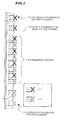
- FIG. 1 is a schematic diagram showing an elevational view of a mobile communication base station antenna 100 in the first embodiment according to the invention.
- a mobile communication base station antenna 100 of the present invention comprises a plurality of antenna blocks (first polarization diversity antenna block 111 and second polarization diversity antenna block 112 ), each of which comprises a plurality of polarization diversity antenna elements ( ⁇ 45 degree polarization diversity elements 113, 114 ), each of which comprises a plurality of antenna elements (+45 degree antenna element 11 and -45 degree antenna element 12, and +45 degree antenna element 13 and -45 degree antenna element 14 ) that are disposed to be orthogonal to each other, in which the polarization diversity antenna elements ( ⁇ 45 degree polarization diversity elements 113 , expressed in solid line) of one of the polarization diversity antenna blocks (first polarization diversity antenna block 111 ) are alternately interposed between the polarization diversity antenna elements ( ⁇ 45 degree polarization diversity elements 114, expressed in broken line) of another one of the polarization diversity antenna blocks (second polarization diversity antenna block 112 ), and tilt angles in the vertical plane of the respective antenna blocks (first polarization
- FIGS. 1 , 3 and 5 a series of the polarization diversity antenna elements are partially omitted from drawings.
- the first polarization diversity antenna block 111 and the second polarization diversity antenna block 112 are combined with each other to be vertically arranged.
- the polarization diversity antenna elements (the ⁇ 45 degree polarization diversity elements 113, 114 ) are disposed with a predetermined distance in the vertical direction in each of the polarization diversity antenna blocks (the first polarization diversity antenna block 111 and the second polarization diversity antenna block 112 ). In an overlapped portion, the ⁇ 45 degree polarization diversity elements 114 of the second polarization diversity antenna block 112 are interposed between each interval between the respective ⁇ 45 degree polarization diversity elements 113 of the first polarization diversity antenna block 111.
- each of the +45 degree polarization diversity antenna elements 113, 114 comprises +45 degree polarization diversity and -45 degree polarization diversity.
- Each of the first polarization diversity antenna block 111 and the second polarization diversity antenna block 112 provides the polarization diversity, so that the mobile communication base station antenna 100 of FIG. 1 comprises four antenna blocks divided by space and polarization. Accordingly, the mobile communication base station antenna. 100 can be used as an array antenna for 4 ⁇ 4 MIMO communication.
- FIG. 2 is a schematic diagram showing a perspective view of the mobile communication base station antenna of FIG. 1 .
- the ⁇ 45 degree polarization diversity antenna elements 113, 114 are disposed with a predetermined interval in the vertical direction.
- the ⁇ 45 degree polarization diversity elements 114 composing the second polarization diversity antenna block 112 axe interposed between each interval between the respective ⁇ 45 degree polarization diversity elements 113 composing the first polarization diversity antenna block 111 .
- an upper part of each of the ⁇ 45 degree polarization diversity elements 113 is colored in black for convenience, so as to clarify a difference between the ⁇ 45 degree polarization diversity elements 113 and the ⁇ 45 degree polarization diversity elements 114.
- FIGS. 3A and 3B are explanatory diagrams of a structure of the first polarization diversity antenna block 111 in the mobile communication base station antenna in the embodiment according to the invention, wherein FIG. 3A is a front view thereof and FIG. 3B is a side view thereof.
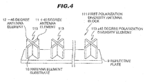
- FIG. 4 is an explanatory diagram showing a perspective view of the first polarization diversity antenna block 111 in the mobile communication base station antenna in the embodiment shown in FIG. 1 .
- FIGS.3A, 3B and FIG. 4 although the first polarization diversity antenna, block 111 is shown, the first polarization diversity antenna block 111 has a structure similar to the second polarization diversity antenna block 112.
- the first polarization diversity antenna block 111 has a structure in which the ⁇ 45 degree polarization diversity antenna elements are disposed in the array shape along a longitudinal direction of a reflective plate 9.
- the antenna elements ( ⁇ 45 degree antenna elements 113 in FIGS. 3A-3B and FIG. 4 ) 113 are construed by combining the +45 degree antenna element 11 and the -45 degree antenna element 12 to have a cross-shape in its cross sectional view.
- Each of the antenna elements 11, 12 is construed by forming an antenna element patters (not shown) comprising a metal, a combination of the metal and a dielectric material, or the like on a surface of an antenna element substrate 10.
- the antenna elements 11, 12 are respectively connected to different port (feeding points, not shown) via feeding lines (not shown).
- positions of the antenna elements may be changed, and a combination of antenna elements in the polarization diversity antenna element may be changed.
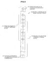
- FIG. 5 is a schematic diagram showing an elevational view of a mobile communication base station antenna 200 in the second embodiment according to the invention.
- the mobile communication base station antenna 200 comprises a first polarization diversity antenna block 211 comprising vertical-horizontal polarization diversity antenna elements 213 and a second polarization diversity antenna block 212 comprising vertical-horizontal polarization antenna elements 214.
- the ⁇ 45 degree polarization diversity elements 113, 114 are replaced with the vertical-horizontal polarization diversity antenna elements 213, 214.
- the vertical-horizontal polarization diversity antenna elements 213 is expressed in solid line
- the vertical-horizontal polarization diversity antenna elements 214 is expressed in broken line.
- the vertical-horizontal polarization diversity antenna elements 213 and the vertical-horizontal polarization diversity antennas elements 214 composes different polarization diversity antenna blocks 211, 212, respectively.
- FIG. 6 is a schematic diagram showing a perspective view of the mobile communication base station antenna 200 of FIG. 5 .
- the vertical-horizontal polarization diversity antenna elements 213, 214 are disposed with a predetermined interval in the vertical direction.
- the vertical-horizontal polarization diversity elements 214 composing the second polarization diversity antenna block 212 are interposed between each interval between the respective vertical-horizontal polarization diversity elements 213 composing the first polarization diversity antenna block 211.
- an upper part of each of the vertical-horizontal polarization diversity elements 213 is colored in black for convenience, so as to clarify a difference between the vertical-horizontal polarization diversity elements 213 and the vertical-horizontal polarization diversity elements 214.
- FIG. 7 is a schematic diagram showing an elevational view of a mobile communication base station antenna 300 in the third embodiment according to the invention
- the mobile communication base station antenna 300 comprises a first polarization diversity antenna block 311 comprising ⁇ 45 degree polarization diversity antenna elements 313 and a second polarization diversity antenna block 312 comprising vertical-horizontal polarization antenna elements 314.
- the ⁇ 45 degree polarization diversity elements 313 are combined with the vertical-horizontal polarization diversity antenna elements 314.
- the shape of the antenna elements is not limited.
- the ⁇ 45 degree polarization diversity antenna elements 313 is expressed in solid line
- the vertical-horizontal polarization diversity antenna elements 314 is expressed in broken line.
- the ⁇ 45 degree polarization diversity antenna, elements 313 and the vertical-horizontal polarization diversity antenna elements 314 composes different polarization diversity antenna blocks 311, 312, respectively.
- FIG. 8 is a schematic diagram showing a perspective view of the mobile communication base station antenna 300 of FIG. 7 .
- the polarization diversity antenna elements 313, 314 are disposed with a predetermined interval in the vertical direction.
- the polarization diversity elements 314 composing the second polarization diversity antenna block 312 are interposed between each interval between the respective ⁇ 45 degree polarization diversity antenna elements 313 composing the first polarization diversity antenna block 311.
- an upper part of each of the ⁇ 45 degree polarization diversity antenna elements 313 is colored in black for convenience, so as to clarify a difference between the ⁇ 45 degree polarization diversity antenna elements 313 and the vertical-horizontal polarization diversity elements 314.
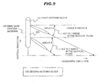
- FIG. 9 is an explanatory diagram showing a side view of a mobile communication base station antenna. 450, in which a directivity in the vertical plane thereof is shown.
- a difference in tilt angle in the vertical plane is provided between a first antenna block 451 comprising antenna elements connected to a first port (not shown) and a second antenna block 452 comprising antenna elements connected to a third port (not shown), that have the same polarization characteristics-
- the first antenna block 451 comprising the antenna elements connected to the first port and the second antenna block 452 comprising the antenna elements connected to the third port are collectivities of the antenna elements 12 (cf. FIG. 1 )
- an antenna block comprising antenna elements connected to a second port and another antenna block comprising antenna element connected to a fourth port are collectivities of the antenna elements 11 (cf. FIG. 1 ).
- a tilt angle in the vertical plane of the first antenna block 451 comprising the antenna elements connected to the first port is set as 3 degrees and a tilt angle in the vertical plane of the second antenna block 452 comprising the antenna elements connected to the third port is set as 6 degrees.
- the antenna block comprising antenna elements connected to the second port and the antenna, block comprising antenna elements connected to the fourth port are not shown in FIG. 9 for convenience of explanation.
- a tilt angle 453 in the vertical plane in the in the antenna element connected to the first port included in the first polarization diversity antenna block 111 (of FIG. 1 ) is set as an angle A
- a tilt angle 454 in the vertical plane in the antenna element connected to the third port included in the second polarization diversity antenna block 112 (cf. FIG. 1 ) is set as an angle B.
- the angle A (degree) is smaller than the angle B (degree) (A ⁇ B).
- the first polarization diversity antenna block 111 and the second polarization diversity antenna block 112 are vertically arranged. Therefore, as shown in FIG. 9 , a difference is provided between the angle A of the tilt angle 453 in the vertical plane of the first polarization diversity antenna block 111 (the first antenna block 451 comprising the antenna element connected to the first port) and the angle B of the tilt angle 454 of the second polarization diversity antenna block 112 (the second antenna block 452 comprising the antenna element connected to the third port) that have the same polarization characteristics. Accordingly, the antenna correlation coefficient between the first polarization diversity antenna block 111 and the second polarization diversity antenna block 112 can be decreased.
- the mobile communication base station antenna since the mobile communication base station antenna has the sharp directivity in the vertical plane, when the tilt angle in the vertical plane is changed, a three-dimensional directivity, particularly a directivity of the main beam varies greatly. Therefore, overlap of the directivities of the respective antenna blocks can be reduced by providing a difference in the tilt angles in the vertical plane, thereby decreasing the correlation coefficient.
- This operation of decreasing the correlation coefficient can be conducted in the antenna block comprising the antenna element connected to the second port (the antenna element of the first polarization diversity antenna block 111 ) and the antenna block comprising the antenna element connected to the fourth port (the antenna element of the second polarization diversity antenna block 112 ) that have the same polarization characteristics, by providing a difference between the tilt angles in the vertical plane.
- this operation of decreasing the correlation coefficient can be also conducted between the respective antenna blocks comprising the antenna elements having different polarization characteristics.
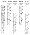
- FIGS. 10A to 10E are schematic diagrams showing elevational views of the mobile communication base station antenna of FIG. 1 that are disassembled by antenna blocks comprising antenna elements connected to respective ports, wherein FIG. 10A shows an elevational view of the mobile communication base station antenna comprising antenna blocks, FIG. 10B is an elevational view of an antenna block connected to the first port, FIG. 10C is an elevational view of an antenna block connected to the third port, FIG. 10D is an elevational view of an antenna block connected to the second port, FIG. 10E is an elevational view of an antenna block connected to the fourth port,
- FIGS. 11A to 11E are schematic diagrams showing perspective views of the mobile communication base station antenna of FIG. 1 that are disassembled by antenna blocks comprising antenna elements connected to respective ports, wherein FIG. 11A shows a perspective view of the mobile communication base station antenna comprising antenna blocks, FIG. 11B is a perspective view of an antenna block connected to the first port, FIG. 11C is a perspective view of an antenna block connected to the third port, FIG. 11D is a perspective view of an antenna block connected to the second port, FIG. 11E is a perspective view of an antenna block connected to the fourth port.
- the mobile communication base station antenna shown in FIG. 10A is disassembled into respective antenna blocks comprising the antenna elements connected to the respective ports.
- the mobile communication base station antenna shown in FIG. 11A is disassembled into respective antenna blocks comprising the antenna elements connected to the respective ports.
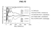
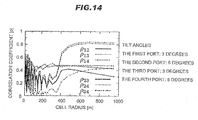
- FIGS. 12 to 14 are graphs showing the simulation results.
- a vertical axis shows an absolute value p of a correlation coefficient between antenna blocks comprising antenna elements connected to the respective ports shown in FIGS. 10A to 10E
- a horizontal axis shows a cell radius of the base station.
- FIG. 12 is a graph showing a relationship of the antenna correlation coefficient between the cell radius, when no difference is provided in the tilt angles in the vertical plane between the respective antenna blocks. Namely, the tilt angles in the vertical plane of the antenna block comprising the antenna element connected to the first port, the antenna block comprising the antenna, element connected to the second port, the antennas block comprising the antenna element connected to the third port, and the antenna block comprising the antenna element connected to the fourth port are 3 degrees.
- FIG. 13 is a graph showing a relationship of the antenna correlation coefficient between the cell radius, when a difference in the tilt angles in the vertical plane between upper antenna block and the lower antenna block is provided, Namely, the tilt angles in the vertical plane of the antenna block comprising the antenna element connected to the first port and the antenna block comprising the antenna element connected to the second port are set as 3 degrees. The tilt angles in the vertical plane of the antenna block comprising the antenna element connected to the third port and the antenna block comprising the antenna element connected to the fourth port are set as 6 degrees.
- FIG. 14 is a graph showing a relationship of the antenna correlation coefficient between the cell radius, when the tilt angles in the vertical plane of the antenna blocks including the antenna elements connected to the first port and the antenna blocks including the antenna elements connected to the third port are set as 3 degrees.
- the tilt angles in the vertical plane of the antenna blocks including the antenna elements connected to the second port and the antenna blocks including the antenna elements connected to the fourth port are set as 6 degrees.
- the main beam is directed to a cell edge (i.e. edge of the cell radius, wherein the cell radius is a radius of an arrival range of the signals).
- the tilt angle in the vertical plane is set as 6 degrees which is greater than 3 degrees, so as to suppress the interference with the other cells.
- reference numerals indicate two port numbers based on which the correlation coefficient is calculated, for example, " ⁇ 12 " indicates the correlation coefficient between the antenna block connected to the first port and the antenna block connected to the second port.
- the correlation coefficient between the antenna blocks can be reduced by adjusting the tilt angle in the vertical plane of the beam such that the directivities will be orthogonal to each other (i.e. the beams will not interfere with each other). Since any null point does not exist in directivities of all ports, enhancement in performance can be expected.
- FIG. 14 shows that the correlation coefficient between the antenna blocks can be reduced to be 0.7 or less other in the direction other than the main beam direction (within the cell radius of 400 m).
- an overall length of the mobile communication base station antenna 100 can be shortened by overlapping the antenna elements 11 , 12 of the first and second polarization diversity antenna blocks 111 , 112 in a middle part of the mobile communication base station antenna in the present invention. It is possible to improve the correlation coefficient between the antenna blocks comprising the antenna element connected to the respective ports by changing the beam tilt angle in the vertical plane (the tilt angle in the vertical plane) between the upper and lower polarization diversity antenna blocks 111, 112 .
- the directivity can be changed by changing the beam tilt angle in the vertical plane (the tilt angle in the vertical plane) between the upper and lower polarization diversity antenna blocks 111 , 112 , thereby reducing the correlation coefficient between the polarization diversity antenna blocks 111 , 112 . Further, a space multiplexing effect of MIMO can be enhanced by decreasing the correlation coefficient between the respective antenna blocks, thereby enhancing the data transmission efficiency.
- FIGS. 12 , 13 , and 14 only the results of the simulation calculation in the mobile communication base station antenna 100 of FIG. 1 are shown. However, results similar to those in FIGS. 12 , 13 , and 14 can be provided in the simulation calculation of the mobile communication base station antennas 200, 300 of FIGS. 5 and 7 .
- an overall length of the mobile communication base station antenna 200 can be shortened by overlapping the antenna elements of the first and second polarization diversity antenna blocks 211 , 212 in a middle part of the mobile communication base station antenna 200 . It is possible to improve the correlation coefficient between the antenna blocks 211 , 212 comprising the antenna element connected to the respective ports by changing the beam tilt angle in the vertical plane (the tilt angle in the vertical plane) between the upper and lower polarization diversity antenna blocks 211 , 212 .
- the directivity can be changed by changing the beam tilt angle in the vertical plane (the tilt angle in the vertical plane) between the upper and lower polarization diversity antenna blocks 211 , 212 , thereby reducing the correlation coefficient between the polarization diversity antenna blocks 211 , 212 . Further, a space multiplexing effect of MIMO can be enhanced by decreasing the correlation coefficient between the respective antenna blocks, thereby enhancing the data transmission efficiency.
- an overall length of the mobile communication base station antenna 300 can be shortened by overlapping the antenna elements of the first and second polarization diversity antenna blocks 311 , 312 in a middle part of the mobile communication base station antenna 300 . It is possible to improve the correlation coefficient between the antenna blocks 311, 312 comprising the antenna element connected to the respective ports by changing the beam tilt angle in the vertical plane (the tilt angle in the vertical plane) between the upper and lower polarization diversity antenna blocks 311 , 312 .
- the directivity can be changed by changing the beam tilt angle in the vertical plane (the tilt angle in the vertical plane) between the upper and lower polarization diversity antenna blocks 311, 312 , thereby reducing the correlation coefficient between the polarization diversity antenna blocks 311 , 312 . Further, a space multiplexing effect of MIMO can be enhanced by decreasing the correlation coefficient between the respective antenna blocks, thereby enhancing the data transmission efficiency.
Applications Claiming Priority (1)
| Application Number | Priority Date | Filing Date | Title |
|---|---|---|---|
| JP2009049765 | 2009-03-03 |
Publications (1)
| Publication Number | Publication Date |
|---|---|
| EP2226890A1 true EP2226890A1 (de) | 2010-09-08 |
Family
ID=42200832
Family Applications (1)
| Application Number | Title | Priority Date | Filing Date |
|---|---|---|---|
| EP10154788A Withdrawn EP2226890A1 (de) | 2009-03-03 | 2010-02-26 | Mobile Kommunikationsbasisstationsantenne |
Country Status (5)
| Country | Link |
|---|---|
| US (1) | US8798679B2 (de) |
| EP (1) | EP2226890A1 (de) |
| JP (1) | JP5351799B2 (de) |
| KR (1) | KR101112726B1 (de) |
| CN (1) | CN101826662B (de) |
Cited By (2)
| Publication number | Priority date | Publication date | Assignee | Title |
|---|---|---|---|---|
| WO2019032813A1 (en) * | 2017-08-11 | 2019-02-14 | Cellphone-Mate, Inc. | RADIO FREQUENCY SIGNAL AMPLIFIER FOR VEHICLES |
| US11329684B2 (en) | 2016-06-17 | 2022-05-10 | Cellphone-Mate, Inc. | Radio frequency signal boosters for vehicles |
Families Citing this family (22)
| Publication number | Priority date | Publication date | Assignee | Title |
|---|---|---|---|---|
| GB0622411D0 (en) * | 2006-11-10 | 2006-12-20 | Quintel Technology Ltd | Phased array antenna system with electrical tilt control |
| KR20090130812A (ko) * | 2008-06-16 | 2009-12-24 | 주식회사 케이엠더블유 | 형상 변경이 가능한 기지국 안테나 |
| JP5464126B2 (ja) * | 2010-11-09 | 2014-04-09 | 日立金属株式会社 | 移動通信用基地局アンテナ、及び移動通信用基地局アンテナシステム |
| CN102916262B (zh) * | 2011-08-04 | 2015-03-04 | 中国电信股份有限公司 | 多模天线与基站 |
| CN102938688B (zh) * | 2011-08-15 | 2015-05-27 | 上海贝尔股份有限公司 | 用于多维天线阵列的信道测量和反馈的方法和设备 |
| US20130162499A1 (en) * | 2011-11-15 | 2013-06-27 | Juniper Networks, Inc. | Apparatus for implementing cross polarized integrated antennas for mimo access points |
| US9191086B2 (en) | 2011-11-15 | 2015-11-17 | Juniper Networks, Inc. | Methods and apparatus for balancing band performance |
| FR2985099B1 (fr) * | 2011-12-23 | 2014-01-17 | Alcatel Lucent | Antenne panneau multibande a polarisation croisee |
| US20140049439A1 (en) * | 2012-08-17 | 2014-02-20 | Jimmy Ho | Compact dual-polarized multiple directly fed & em coupled stepped probe element for ultra wideband performance |
| US9653817B2 (en) * | 2012-09-28 | 2017-05-16 | China Telecom Corporation Limited | Array antenna and base station |
| CN103904428B (zh) * | 2012-12-25 | 2017-03-01 | 中国电信股份有限公司 | Mimo天线及其实现方法 |
| ES2730961T3 (es) * | 2013-02-22 | 2019-11-13 | Quintel Cayman Ltd | Agrupación de antenas múltiple |
| HUE050086T2 (hu) * | 2013-05-31 | 2020-11-30 | Qualcomm Inc | Lineáris elõkódolás teljes dimenziójú MIMO rendszerekben |
| US11387574B2 (en) * | 2013-10-29 | 2022-07-12 | Nokia Shanghai Bell Co., Ltd | Vertically and horizontally polarized omnidirectional antennas and related methods |
| JP2017505075A (ja) * | 2014-01-31 | 2017-02-09 | クインテル テクノロジー リミテッド | ビーム幅制御を伴うアンテナシステム |
| US9553642B2 (en) | 2014-07-28 | 2017-01-24 | Futurewei Technologies, Inc. | Apparatus and methods for cross-polarized tilt antennas |
| US10187130B2 (en) | 2015-02-17 | 2019-01-22 | Futurewei Technologies, Inc. | Apparatus and method to configure antenna beam width |
| DE102015005468A1 (de) | 2015-04-29 | 2016-11-03 | Kathrein-Werke Kg | Antenne |
| GB2538070A (en) * | 2015-05-04 | 2016-11-09 | Kathrein Werke Kg | Antenna system |
| CN107946780A (zh) * | 2017-12-18 | 2018-04-20 | 罗森伯格技术(昆山)有限公司 | 一种一体化的基站天线 |
| CN114946086A (zh) | 2020-01-17 | 2022-08-26 | 株式会社Kmw | 利用四极化天线模块阵列实现波束的空间-极化分离的fdd方式的天线装置 |
| CN116569418A (zh) * | 2020-12-11 | 2023-08-08 | 华为技术有限公司 | 一种阵列天线及基站 |
Citations (5)
| Publication number | Priority date | Publication date | Assignee | Title |
|---|---|---|---|---|
| US20040066333A1 (en) * | 2002-09-27 | 2004-04-08 | Andrew Corporation | Active antenna with interleaved arrays of antenna elements |
| JP2005203841A (ja) | 2004-01-13 | 2005-07-28 | Hitachi Cable Ltd | アンテナ装置 |
| US20070049347A1 (en) * | 2005-08-29 | 2007-03-01 | Navini Networks, Inc. | Method and system for partitioning an antenna array and applying multiple-input-multiple-output and beamforming mechanisms |
| WO2008063111A1 (en) * | 2006-11-23 | 2008-05-29 | Telefonaktiebolaget Lm Ericsson (Publ) | Optimized radiation patterns |
| WO2008126857A1 (ja) * | 2007-04-10 | 2008-10-23 | Nec Corporation | マルチビームアンテナ |
Family Cites Families (80)
| Publication number | Priority date | Publication date | Assignee | Title |
|---|---|---|---|---|
| US5602834A (en) * | 1990-12-07 | 1997-02-11 | Qualcomm Incorporated | Linear coverage area antenna system for a CDMA communication system |
| JPH06196927A (ja) * | 1992-12-24 | 1994-07-15 | N T T Idou Tsuushinmou Kk | ビームチルト・アンテナ |
| WO1994013031A1 (en) * | 1992-12-01 | 1994-06-09 | Ntt Mobile Communications Network Inc. | Multi-beam antenna apparatus |
| US5437055A (en) * | 1993-06-03 | 1995-07-25 | Qualcomm Incorporated | Antenna system for multipath diversity in an indoor microcellular communication system |
| US5724666A (en) * | 1994-03-24 | 1998-03-03 | Ericsson Inc. | Polarization diversity phased array cellular base station and associated methods |
| US6201801B1 (en) * | 1994-03-24 | 2001-03-13 | Ericsson Inc. | Polarization diversity phased array cellular base station and associated methods |
| US6005516A (en) * | 1995-06-08 | 1999-12-21 | Metawave Communications Corporation | Diversity among narrow antenna beams |
| US6351237B1 (en) * | 1995-06-08 | 2002-02-26 | Metawave Communications Corporation | Polarization and angular diversity among antenna beams |
| US5966102A (en) * | 1995-12-14 | 1999-10-12 | Ems Technologies, Inc. | Dual polarized array antenna with central polarization control |
| US5923296A (en) * | 1996-09-06 | 1999-07-13 | Raytheon Company | Dual polarized microstrip patch antenna array for PCS base stations |
| US6900775B2 (en) * | 1997-03-03 | 2005-05-31 | Celletra Ltd. | Active antenna array configuration and control for cellular communication systems |
| US6167286A (en) * | 1997-06-05 | 2000-12-26 | Nortel Networks Corporation | Multi-beam antenna system for cellular radio base stations |
| US6094165A (en) * | 1997-07-31 | 2000-07-25 | Nortel Networks Corporation | Combined multi-beam and sector coverage antenna array |
| SE512439C2 (sv) * | 1998-06-26 | 2000-03-20 | Allgon Ab | Dubbelbandsantenn |
| SE513138C2 (sv) * | 1998-11-20 | 2000-07-10 | Ericsson Telefon Ab L M | Förfarande och arrangemang för att öka isoleringen mellan antenner |
| US6198434B1 (en) * | 1998-12-17 | 2001-03-06 | Metawave Communications Corporation | Dual mode switched beam antenna |
| US6583760B2 (en) * | 1998-12-17 | 2003-06-24 | Metawave Communications Corporation | Dual mode switched beam antenna |
| SE517197C2 (sv) * | 1999-04-15 | 2002-05-07 | Ericsson Telefon Ab L M | Adaptiv sektorindelning |
| US6583763B2 (en) * | 1999-04-26 | 2003-06-24 | Andrew Corporation | Antenna structure and installation |
| US6370398B1 (en) * | 1999-05-24 | 2002-04-09 | Telaxis Communications Corporation | Transreflector antenna for wireless communication system |
| WO2001031747A1 (es) * | 1999-10-26 | 2001-05-03 | Fractus, S.A. | Agrupaciones multibanda de antenas entrelazadas |
| US6211841B1 (en) * | 1999-12-28 | 2001-04-03 | Nortel Networks Limited | Multi-band cellular basestation antenna |
| US7254171B2 (en) * | 2000-01-20 | 2007-08-07 | Nortel Networks Limited | Equaliser for digital communications systems and method of equalisation |
| US6745051B1 (en) * | 2000-07-10 | 2004-06-01 | Nortel Networks Limited | Six sector antenna structure |
| JP2002124816A (ja) * | 2000-10-16 | 2002-04-26 | Mitsubishi Electric Corp | 偏波ダイバーシチアンテナ |
| JP4161530B2 (ja) | 2000-10-26 | 2008-10-08 | 日立電線株式会社 | 2周波共用アレイアンテナ |
| AU2002227047A1 (en) * | 2000-11-17 | 2002-05-27 | Ems Technologies Inc. | Radio frequency isolation card |
| US6388622B1 (en) * | 2001-01-11 | 2002-05-14 | Trw Inc. | Pole antenna with multiple array segments |
| FR2823017B1 (fr) * | 2001-03-29 | 2005-05-20 | Cit Alcatel | Antenne multibande de telecommunications |
| KR100510434B1 (ko) * | 2001-04-09 | 2005-08-26 | 니폰덴신뎅와 가부시키가이샤 | Ofdm신호전달 시스템, ofdm신호 송신장치 및ofdm신호 수신장치 |
| DE60128837T2 (de) * | 2001-04-16 | 2008-02-28 | Fractus, S.A. | Doppelbandige dualpolarisierte gruppenantenne |
| GB0125349D0 (en) * | 2001-10-22 | 2001-12-12 | Qinetiq Ltd | Antenna system |
| US6816124B2 (en) * | 2001-11-07 | 2004-11-09 | Ems Technologies, Inc. | Linearly-polarized dual-band base-station antenna |
| GB0224341D0 (en) * | 2002-10-19 | 2002-11-27 | Qinetiq Ltd | Mobile radio base station |
| DE60221150T2 (de) * | 2001-11-14 | 2008-03-20 | Quintel Technology Ltd. | Antennensystem |
| EP1353405A1 (de) * | 2002-04-10 | 2003-10-15 | Huber & Suhner Ag | Dualbandantenne |
| US6747606B2 (en) * | 2002-05-31 | 2004-06-08 | Radio Frequency Systems Inc. | Single or dual polarized molded dipole antenna having integrated feed structure |
| JP2004080353A (ja) * | 2002-08-16 | 2004-03-11 | Nippon Telegr & Teleph Corp <Ntt> | 適応アレーアンテナを用いた通信装置及び通信制御方法 |
| DE10256960B3 (de) * | 2002-12-05 | 2004-07-29 | Kathrein-Werke Kg | Zweidimensionales Antennen-Array |
| US7272364B2 (en) * | 2002-12-30 | 2007-09-18 | Motorola, Inc. | Method and system for minimizing overlap nulling in switched beams |
| US20040157645A1 (en) * | 2003-02-12 | 2004-08-12 | Smith Adrian David | System and method of operation an array antenna in a distributed wireless communication network |
| US6791507B2 (en) * | 2003-02-13 | 2004-09-14 | Telefonaktiebolaget Lm Ericsson (Publ) | Feed network for simultaneous generation of narrow and wide beams with a rotational-symmetric antenna |
| JP3994886B2 (ja) * | 2003-03-03 | 2007-10-24 | 三菱電機株式会社 | 偏波ダイバーシチアンテナ |
| DE10316786A1 (de) * | 2003-04-11 | 2004-11-18 | Kathrein-Werke Kg | Reflektor, insbesondere für eine Mobilfunk-Antenne |
| US7817096B2 (en) * | 2003-06-16 | 2010-10-19 | Andrew Llc | Cellular antenna and systems and methods therefor |
| US7302278B2 (en) * | 2003-07-03 | 2007-11-27 | Rotani, Inc. | Method and apparatus for high throughput multiple radio sectorized wireless cell |
| GB0325987D0 (en) * | 2003-11-07 | 2003-12-10 | Qinetiq Ltd | Phased array antenna system with controllable electrical tilt |
| US7664533B2 (en) * | 2003-11-10 | 2010-02-16 | Telefonaktiebolaget Lm Ericsson (Publ) | Method and apparatus for a multi-beam antenna system |
| US7277731B2 (en) * | 2003-12-23 | 2007-10-02 | Motorola, Inc. | Adaptive diversity antenna system |
| US7460082B2 (en) * | 2003-12-30 | 2008-12-02 | Intel Corporation | Sectored antenna systems for WLAN |
| US7409001B2 (en) * | 2004-08-12 | 2008-08-05 | Nokia Corporation | Method and apparatus using coordinate interleaving to increase diversity in a MIMO system |
| WO2006065172A1 (en) | 2004-12-13 | 2006-06-22 | Telefonaktiebolaget L M Ericsson (Publ) | An antenna arrangement and a method relating thereto |
| US7415288B1 (en) * | 2005-01-07 | 2008-08-19 | Zte (Usa) Inc. | Techniques for providing efficient transmit diversity and bandwidth segmentation in a wireless communication system |
| US9179319B2 (en) * | 2005-06-16 | 2015-11-03 | Qualcomm Incorporated | Adaptive sectorization in cellular systems |
| WO2007011295A1 (en) * | 2005-07-22 | 2007-01-25 | Powerwave Technologies Sweden Ab | Antenna arrangement with interleaved antenna elements |
| US7751372B2 (en) * | 2005-09-23 | 2010-07-06 | Peter Monsen | Technique for adaptive data rate communication over fading dispersive channels |
| WO2007037732A1 (en) * | 2005-09-30 | 2007-04-05 | Telefonaktiebolaget Lm Ericsson (Publ) | Method and device for polarization correction in user equipment |
| US7538740B2 (en) * | 2006-03-06 | 2009-05-26 | Alcatel-Lucent Usa Inc. | Multiple-element antenna array for communication network |
| CA2542445A1 (en) * | 2006-04-07 | 2007-10-07 | Tenxc Wireless Inc. | Adaptive multi-beam system |
| US7660573B2 (en) * | 2006-04-14 | 2010-02-09 | Elmaleh David R | Infrastructure for wireless telecommunication networks |
| KR101119228B1 (ko) * | 2006-04-27 | 2012-03-21 | 레이스팬 코포레이션 | 메타물질 구조에 기반한 안테나, 장치 및 시스템 |
| JP2007329666A (ja) * | 2006-06-07 | 2007-12-20 | Ntt Docomo Inc | アレーアンテナ装置 |
| GB0622435D0 (en) * | 2006-11-10 | 2006-12-20 | Quintel Technology Ltd | Electrically tilted antenna system with polarisation diversity |
| JP5209641B2 (ja) * | 2006-12-22 | 2013-06-12 | テレフオンアクチーボラゲット エル エム エリクソン(パブル) | アンテナ装置 |
| WO2008086415A1 (en) * | 2007-01-09 | 2008-07-17 | Viasat, Inc. | Multi-antenna satellite system with wireless interface to vehicle |
| CN101355780B (zh) * | 2007-07-23 | 2011-12-07 | 中兴通讯股份有限公司 | 时分同步码分多址接入系统的线性覆盖系统及通信方法 |
| US8237602B2 (en) * | 2007-07-24 | 2012-08-07 | Lockheed Martin Corporation | Distributed and coordinated electronic warfare system |
| US7808440B2 (en) * | 2007-08-03 | 2010-10-05 | Toyota Jidosha Kabushiki Kaisha | Multiple-resonance antenna |
| US8059553B2 (en) * | 2007-08-21 | 2011-11-15 | Fimax Technology Limited | Adaptive interference control |
| KR100902294B1 (ko) * | 2007-08-22 | 2009-06-10 | 삼성전자주식회사 | 환경 변화에 적응적인 mimo 안테나 시스템 |
| US8165095B2 (en) * | 2007-11-30 | 2012-04-24 | Motorola Mobility, Inc. | System and method to improve RF simulations |
| US8368609B2 (en) * | 2008-10-21 | 2013-02-05 | Laird Technologies, Inc. | Omnidirectional multiple input multiple output (MIMO) antennas with polarization diversity |
| US8692730B2 (en) * | 2009-03-03 | 2014-04-08 | Hitachi Metals, Ltd. | Mobile communication base station antenna |
| US20100227646A1 (en) * | 2009-03-03 | 2010-09-09 | Hitachi Cable, Ltd. | Mobile communication base station antenna |
| US9190715B2 (en) * | 2010-01-19 | 2015-11-17 | Quintel Technology Limited | Method and apparatus for antenna radiation pattern sweeping |
| US8674895B2 (en) * | 2011-05-03 | 2014-03-18 | Andrew Llc | Multiband antenna |
| US9293809B2 (en) * | 2011-06-30 | 2016-03-22 | Intel Corporation | Forty-five degree dual broad band base station antenna |
| WO2013006416A1 (en) * | 2011-07-06 | 2013-01-10 | Cardiac Pacemakers, Inc. | Multi-band loaded antenna |
| US8422540B1 (en) * | 2012-06-21 | 2013-04-16 | CBF Networks, Inc. | Intelligent backhaul radio with zero division duplexing |
| US8467363B2 (en) * | 2011-08-17 | 2013-06-18 | CBF Networks, Inc. | Intelligent backhaul radio and antenna system |
-
2010
- 2010-02-26 EP EP10154788A patent/EP2226890A1/de not_active Withdrawn
- 2010-03-02 JP JP2010045511A patent/JP5351799B2/ja not_active Expired - Fee Related
- 2010-03-02 KR KR1020100018654A patent/KR101112726B1/ko not_active IP Right Cessation
- 2010-03-02 CN CN201010122252.3A patent/CN101826662B/zh not_active Expired - Fee Related
- 2010-03-02 US US12/659,254 patent/US8798679B2/en not_active Expired - Fee Related
Patent Citations (6)
| Publication number | Priority date | Publication date | Assignee | Title |
|---|---|---|---|---|
| US20040066333A1 (en) * | 2002-09-27 | 2004-04-08 | Andrew Corporation | Active antenna with interleaved arrays of antenna elements |
| JP2005203841A (ja) | 2004-01-13 | 2005-07-28 | Hitachi Cable Ltd | アンテナ装置 |
| US20070049347A1 (en) * | 2005-08-29 | 2007-03-01 | Navini Networks, Inc. | Method and system for partitioning an antenna array and applying multiple-input-multiple-output and beamforming mechanisms |
| WO2008063111A1 (en) * | 2006-11-23 | 2008-05-29 | Telefonaktiebolaget Lm Ericsson (Publ) | Optimized radiation patterns |
| WO2008126857A1 (ja) * | 2007-04-10 | 2008-10-23 | Nec Corporation | マルチビームアンテナ |
| EP2058900A1 (de) * | 2007-04-10 | 2009-05-13 | NEC Corporation | Mehrstrahlenantenne |
Non-Patent Citations (2)
| Title |
|---|
| JUKKA J A LEMPIAINEN ET AL: "Signal Correlations and Diversity Gain of Two-Beam Microcell Antenna", IEEE TRANSACTIONS ON VEHICULAR TECHNOLOGY, IEEE SERVICE CENTER, PISCATAWAY, NJ, US, vol. 47, no. 3, 1 August 1998 (1998-08-01), XP011063733, ISSN: 0018-9545 * |
| VAUGHAN R G ET AL: "ANTENNA DIVERSITY IN MOBILE COMMUNICATIONS", IEEE TRANSACTIONS ON VEHICULAR TECHNOLOGY, IEEE SERVICE CENTER, PISCATAWAY, NJ, US, vol. VT-36, no. 4, 1 November 1987 (1987-11-01), pages 149 - 172, XP000949105, ISSN: 0018-9545 * |
Cited By (5)
| Publication number | Priority date | Publication date | Assignee | Title |
|---|---|---|---|---|
| US11329684B2 (en) | 2016-06-17 | 2022-05-10 | Cellphone-Mate, Inc. | Radio frequency signal boosters for vehicles |
| WO2019032813A1 (en) * | 2017-08-11 | 2019-02-14 | Cellphone-Mate, Inc. | RADIO FREQUENCY SIGNAL AMPLIFIER FOR VEHICLES |
| US10623036B2 (en) | 2017-08-11 | 2020-04-14 | Cellphone-Mate, Inc. | Radio frequency signal boosters for vehicles |
| US10992332B2 (en) | 2017-08-11 | 2021-04-27 | Cellphone-Mate, Inc. | Radio frequency signal boosters for vehicles |
| US11722165B2 (en) | 2017-08-11 | 2023-08-08 | Cellphone-Mate, Inc. | Radio frequency signal boosters for vehicles |
Also Published As
| Publication number | Publication date |
|---|---|
| CN101826662A (zh) | 2010-09-08 |
| US20100227647A1 (en) | 2010-09-09 |
| CN101826662B (zh) | 2015-11-25 |
| KR20100099666A (ko) | 2010-09-13 |
| JP5351799B2 (ja) | 2013-11-27 |
| KR101112726B1 (ko) | 2012-03-13 |
| JP2010233215A (ja) | 2010-10-14 |
| US8798679B2 (en) | 2014-08-05 |
Similar Documents
| Publication | Publication Date | Title |
|---|---|---|
| US8798679B2 (en) | Mobile communication base station antenna | |
| US8692730B2 (en) | Mobile communication base station antenna | |
| US11239572B2 (en) | Beam-steering reconfigurable antenna arrays | |
| US20210242574A1 (en) | Small cell antennas suitable for mimo operation | |
| US9806425B2 (en) | High performance low profile antennas | |
| US20170062952A1 (en) | Dual band, multi column antenna array for wireless network | |
| EP2710668B1 (de) | Dreipoliges antennenelement und gruppenantenne | |
| US20100227646A1 (en) | Mobile communication base station antenna | |
| US20200243951A1 (en) | Compact omnidirectional antennas having stacked reflector structures | |
| EP2673838A1 (de) | Hochleistungsantennen mit niedrigprofil | |
| JP6282469B2 (ja) | アンテナ | |
| JP6397563B2 (ja) | 漏れ波アンテナ | |
| JP5307651B2 (ja) | アンテナ装置 | |
| CN110970740B (zh) | 天线系统 | |
| CN107359424A (zh) | 一种阵列天线 | |
| CN102646872B (zh) | 天线、复合天线及射频收发系统 | |
| KR200320101Y1 (ko) | 삼중 편파 안테나 | |
| JP2019080128A (ja) | 円偏波無指向性アンテナ、アレイアンテナ及びそれを用いた偏波ダイバーシティ通信システム | |
| EP0749216A1 (de) | Diversitifantenne, insbesondere für mobile mikrozellulare Kommunikationssysteme, und Kommunikationsverfahren mit einer solchen Antenne | |
| CN110970739B (zh) | 天线系统 | |
| JPH09130141A (ja) | アンテナ | |
| CN117044128A (zh) | 四极化天线阵列及利用其的波束空间极化分离 | |
| Arai | Adaptive pattern controlled handset antenna by analog phase shifters |
Legal Events
| Date | Code | Title | Description |
|---|---|---|---|
| PUAI | Public reference made under article 153(3) epc to a published international application that has entered the european phase |
Free format text: ORIGINAL CODE: 0009012 |
|
| AK | Designated contracting states |
Kind code of ref document: A1 Designated state(s): AT BE BG CH CY CZ DE DK EE ES FI FR GB GR HR HU IE IS IT LI LT LU LV MC MK MT NL NO PL PT RO SE SI SK SM TR |
|
| AX | Request for extension of the european patent |
Extension state: AL BA RS |
|
| 17P | Request for examination filed |
Effective date: 20110308 |
|
| 17Q | First examination report despatched |
Effective date: 20121023 |
|
| STAA | Information on the status of an ep patent application or granted ep patent |
Free format text: STATUS: THE APPLICATION IS DEEMED TO BE WITHDRAWN |
|
| 18D | Application deemed to be withdrawn |
Effective date: 20130306 |