EP2226561A2 - Ceramic glow plug - Google Patents
Ceramic glow plug Download PDFInfo
- Publication number
- EP2226561A2 EP2226561A2 EP10001740A EP10001740A EP2226561A2 EP 2226561 A2 EP2226561 A2 EP 2226561A2 EP 10001740 A EP10001740 A EP 10001740A EP 10001740 A EP10001740 A EP 10001740A EP 2226561 A2 EP2226561 A2 EP 2226561A2
- Authority
- EP
- European Patent Office
- Prior art keywords
- protective tube
- glow plug
- sleeve
- plug body
- plug
- Prior art date
- Legal status (The legal status is an assumption and is not a legal conclusion. Google has not performed a legal analysis and makes no representation as to the accuracy of the status listed.)
- Withdrawn
Links
Images

Classifications
-
- F—MECHANICAL ENGINEERING; LIGHTING; HEATING; WEAPONS; BLASTING
- F23—COMBUSTION APPARATUS; COMBUSTION PROCESSES
- F23Q—IGNITION; EXTINGUISHING-DEVICES
- F23Q7/00—Incandescent ignition; Igniters using electrically-produced heat, e.g. lighters for cigarettes; Electrically-heated glowing plugs
- F23Q7/001—Glowing plugs for internal-combustion engines
Definitions
- a further advantageous development of the invention provides that the protective tube is electrically isolated from the plug body.
- This can be achieved, for example, in that the section of the sleeve projecting into the plug body is surrounded by a ceramic ring or a ceramic sleeve, so that an electrically conductive contact between the protective tube and the plug body is prevented.
- the protective tube is electrically isolated from the plug body, it can be used for measuring and / or monitoring functions, for example as ionization or as a temperature sensor, in particular by the protective tube is designed as a measuring resistor or as a thermocouple.
- This aspect of the invention may also have independent significance.
- the present invention therefore also relates to a glow plug with a ceramic glow plug, a thermowell surrounding the glow plug and a plug body from which protrudes the protective tube, wherein the protective tube is electrically isolated from the plug body.
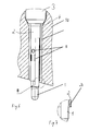
- FIG. 3 shows a schematic representation of another embodiment of a glow plug. This embodiment differs from that in FIG. 1 illustrated embodiment essentially in that the protective tube 2 narrows at its end remote from the plug body 3 end and engages around a tapered portion of the glow plug 1 around.
- the protective tube 2 can hold in this way the glow plug 1 in the case of a Glühmannbruchs form fit.
Landscapes
- Engineering & Computer Science (AREA)
- Chemical & Material Sciences (AREA)
- Combustion & Propulsion (AREA)
- Mechanical Engineering (AREA)
- General Engineering & Computer Science (AREA)
- Resistance Heating (AREA)
Abstract
Description
Die Erfindung geht aus von einer Glühkerze mit den im Oberbegriff des Anspruchs 1 angegebenen Merkmalen. Eine solche Glühkerze ist beispielsweise aus der
Aus der
Aus der
Die
Aufgabe der Erfindung ist es deshalb, einen Weg aufzuzeigen, wie mit geringem Aufwand das Schutzrohr eines keramischen Glühstifts mit dem Kerzenkörper einer Glühkerze verbunden werden kann.The object of the invention is therefore to show a way, as with little effort, the protective tube of a ceramic glow plug can be connected to the plug body of a glow plug.
Diese Aufgabe wird erfindungsgemäß durch eine Glühkerze mit den im Anspruch 1 angegebenen Merkmalen gelöst. Vorteilhafte Weiterbildungen der Erfindung sind Gegenstand der Unteransprüche.This object is achieved by a glow plug with the features specified in
Bei einer erfindungsgemäßen Glühkerze steckt in dem Kerzenkörper eine Hülse, die das Schutzrohr umgibt und mit dem Schutzrohr verschweißt ist. Auf diese Weise lassen sich die Vorteile unterschiedliche Verbindungstechniken nutzen und deren Nachteile vermeiden.In a glow plug according to the invention inserted in the plug body, a sleeve which surrounds the protective tube and is welded to the protective tube. In this way, the advantages of different connection techniques can be used and their disadvantages avoided.
Beispielsweise kann die Hülse in den Kerzenkörper eingepresst und anschließend das Schutzrohr mit dem keramischen Glühstift in die Hülse eingesetzt werden. Beim Einpressen der Hülse besteht dabei keine Gefahr einer Beschädigung des keramischen Glühstifts. Eine Verschweißung des später eingesetzten Schutzrohrs mit der Hülse ist ohne Schwierigkeiten möglich, da das Material der Hülse problemlos geeignet gewählt werden kann, insbesondere können die Hülse und das Schutzrohr aus dem gleichen Material gefertigt sein.For example, the sleeve can be pressed into the plug body and then the protective tube with the ceramic glow plug can be inserted into the sleeve. When pressing the sleeve there is no risk of damage to the ceramic glow plug. A welding of the later used protective tube with the sleeve is possible without difficulty, since the material of the sleeve can be chosen easily suitable, in particular, the sleeve and the protective tube can be made of the same material.
Eine vorteilhafte Weiterbildung der Erfindung sieht vor, dass ein Abschnitt der Hülse, der mit dem Schutzrohr verschweißt ist, aus dem Kerzenkörper herausragt. Besonders bevorzugt ist dabei, dass die Hülse in dem aus dem Kerzenkörper herausragenden Abschnitt eine kleinere Wandstärke als in einem von dem Kerzenkörper umgebenen Abschnitt aufweist. Eine kleinere Wandstärke erleichtert nämlich vorteilhaft das Verschweißen der Hülse mit einem darunter liegenden Abschnitt des Schutzrohres. Umgekehrt wird durch eine größere Wandstärke in einem von dem Kerzenkörper umgebenen Abschnitt vorteilhaft die mechanische Stabilität der Hülse erhöht, so dass sich diese besser in den Kerzenkörper einpressen lässt.An advantageous development of the invention provides that a portion of the sleeve, which is welded to the protective tube, protrudes from the plug body. It is particularly preferred that the sleeve has a smaller wall thickness in the section protruding from the plug body than in a section surrounded by the plug body. Namely, a smaller wall thickness advantageously facilitates the welding of the sleeve to an underlying portion of the protective tube. Conversely, the mechanical stability of the sleeve is advantageously increased by a larger wall thickness in a portion surrounded by the plug body, so that it can be pressed into the plug body better.
Eine weitere vorteilhafte Weiterbildung der Erfindung sieht vor, dass zwischen dem Schutzrohr und dem Kerzenkörper ein Ringspalt ist. Bevorzugt ist auch zwischen dem Schutzrohr und einem von dem Kerzenkörper umgebenen Abschnitt der Hülse ein Ringspalt. Diese Maßnahmen haben den Vorteil, dass die Wärmeableitung von dem Glühstift auf den Kerzenkörper reduziert werden kann.A further advantageous embodiment of the invention provides that between the protective tube and the plug body is an annular gap. Preferably, an annular gap is also between the protective tube and a portion of the sleeve surrounded by the plug body. These measures have the advantage that the heat dissipation from the glow plug to the plug body can be reduced.
Bevorzugt weist die Hülse eine umlaufende Stufe auf. Beispielsweise kann durch eine solche Stufe ein dünnerer Abschnitt der Hülse, der mit dem Schutzrohr verschweißt ist, mit einem dickeren Abschnitt, der in dem Kerzengehäuse angeordnet ist, verbunden werden. Insbesondere kann eine umlaufende Stufe auch genutzt werden, um den Innendurchmesser der Hülse zu verbreitern, so dass zwischen dem Schutzrohr und einem von dem Kerzenkörper umgebenen Abschnitt der Hülse ein Ringspalt ist.Preferably, the sleeve has a circumferential step. For example, by such a step, a thinner portion of the sleeve, which is welded to the protective tube, with a thicker portion which is arranged in the plug housing can be connected. In particular, a circumferential step can also be used to widen the inner diameter of the sleeve, so that between the protective tube and a portion of the sleeve surrounded by the plug body is an annular gap.
Eine weitere vorteilhafte Weiterbildung der Erfindung sieht vor, dass sich das Schutzrohr an seinem von dem Kerzenkörper abgewandten Ende verengt. Auf diese Weise kann das Schutzrohr um einen sich verjüngenden Abschnitt des Glühstifts herum greifen und verhindern, dass der Glühstift im Fall eines Bruchs in den Brennraum fällt.A further advantageous development of the invention provides that the protective tube narrows at its end remote from the plug body. In this way, the protective tube can grip around a tapered portion of the glow plug and prevent the glow plug from falling into the combustion chamber in the event of a break.
Eine weitere vorteilhafte Weiterbildung der Erfindung sieht vor, dass das Schutzrohr in seiner Mantelfläche Öffnungen aufweist. Auf diese Weise können vorteilhaft Turbulenzen in einer Zylinderkopfbohrung erzeugt werden, die einer Russbildung zwischen Zylinderkopf und dem Glühstift mit Schutzrohr entgegenwirken. Die Öffnungen können beispielsweise als Bohrungen, Schlitze, Ausklappungen oder Langlöcher ausgebildet sein. Dieser Aspekt der Erfindung kann auch eigenständige Bedeutung haben. Die vorliegende Erfindung betrifft deshalb auch eine Glühkerze mit einem keramischen Glühstift, einem den Glühstift umgebenden Schutzrohr und einem Kerzenkörper, aus dem das Schutzrohr herausragt, wobei das Schutzrohr in seiner Mantelfläche Öffnungen aufweist.A further advantageous development of the invention provides that the protective tube has openings in its lateral surface. In this way, advantageously turbulence can be generated in a cylinder head bore, which counteract soot formation between the cylinder head and the glow plug with protective tube. The openings may be formed, for example, as holes, slots, folds or slots. This aspect of the invention may also have independent significance. The present invention therefore also relates to a glow plug with a ceramic glow plug, a protective tube surrounding the glow plug and a plug body, from which protrudes the protective tube, wherein the protective tube has openings in its lateral surface.
Eine weitere vorteilhafte Weiterbildung der Erfindung sieht vor, dass das Schutzrohr mindestens zwei Abschnitte aufweist, in denen zwischen dem Schutzrohr und dem Glühstift ein Spalt ist, wobei das Schutzrohr zwischen den beiden Abschnitten eine Engstelle aufweist, an der es an dem Glühstift anliegt. Die Engstelle kann beispielsweise umlaufend ausgebildet sein oder durch mehrere in Umfangsrichtung angeordnete Einprägungen ausgebildet sein. Indem das Schutzrohr den Glühstift nicht auf seiner vollen Länge, sondern nur in einem oder mehreren Abschnitten berührt, können Eigenschwingungen des Glühstifts wirksam gedämpft werden. Dieser Aspekt der Erfindung kann auch eigenständige Bedeutung haben. Die vorliegende Erfindung betrifft deshalb auch eine Glühkerze mit einem keramischen Glühstift, einem den Glühstift umgebenden Schutzrohr und einem Kerzenkörper, aus dem das Schutzrohr herausragt, wobei das Schutzrohr mindestens zwei Abschnitte aufweist, in denen zwischen dem Schutzrohr und dem Glühstift ein Spalt ist, und wobei das Schutzrohr zwischen den beiden Abschnitten eine Engstelle aufweist, an der es an dem Glühstift anliegt.A further advantageous development of the invention provides that the protective tube has at least two sections in which there is a gap between the protective tube and the glow plug, wherein the protective tube has a constriction between the two sections, against which it bears against the glow plug. The constriction may be formed, for example, circumferential or be formed by a plurality of circumferentially arranged indentations. Because the thermowell does not touch the glow plug over its full length but only in one or more sections, natural oscillations of the glow plug can be effectively damped. This aspect of the invention may also have independent significance. The present invention therefore also relates to a glow plug with a ceramic glow plug, a thermowell surrounding the thermowell and a plug body from which protrudes the protective tube, wherein the protective tube has at least two sections in which between the protective tube and the glow plug is a gap, and wherein the protective tube between the two sections has a constriction, where it rests against the glow plug.
Eine weitere vorteilhafte Weiterbildung der Erfindung sieht vor, dass das Schutzrohr an seinem von dem Kerzenkörper abgewandten Ende, aus dem der Glühstift herausragt, einen abgerundeten inneren Rand aufweist. Durch diese Maßnahme lässt sich die Bruchgefahr des keramischen Glühstifts erheblich reduzieren. Bei der Montage oder beim Motorbetrieb kann es nämlich dazu kommen, dass der Glühstift gegen den inneren Rand des Schutzrohres gedrückt wird. Durch die Abrundung des inneren Randes lässt sich die damit verbundene mechanische Belastung wesentlich reduzieren und folglich die Bruchgefahr senken. Dieser Aspekt der Erfindung kann auch eigenständige Bedeutung haben. Die vorliegende Erfindung betrifft deshalb auch eine Glühkerze mit einem keramischen Glühstift, einem den Glühstift umgebenden Schutzrohr und einem Kerzenkörper, aus dem Schutzrohr herausragt, wobei das Schutzrohr an seinem von dem Kerzenkörper angewandten Ende einen abgerundeten inneren Rand aufweist.A further advantageous embodiment of the invention provides that the protective tube has a rounded inner edge at its end remote from the plug body from which the glow plug protrudes. By this measure, the risk of breakage of the ceramic glow plug can be significantly reduced. During assembly or during engine operation, it can happen that the glow plug is pressed against the inner edge of the protective tube. By rounding the inner edge of the associated mechanical stress can be significantly reduced and thus reduce the risk of breakage. This aspect of the invention may also have independent significance. The present invention therefore also relates to a glow plug with a ceramic glow plug, a protective tube surrounding the glow plug and a plug body protruding from the protective tube, wherein the protective tube has a rounded inner edge at its end applied by the plug body.
Eine weitere vorteilhafte Weiterbildung der Erfindung sieht vor, dass das Schutzrohr eine beschichtete Oberfläche aufweist. Beispielsweise kann das Schutzrohr an seiner Außenseite eine katalytische Schicht tragen, um das Abbrennen von eventuell vorhandenem Ruß zu fördern. Geigente Katalysatoren sind beispielsweise Platinwerkstoffe. Möglich ist es auch, das Schutzrohr an seiner Außenseite mit einer Antihaftschicht, beispielsweise einer Nano-Oberflächenbeschichtung, zu versehen. Auf diese Weise lässt sich Ablagerungen von Ruß und sonstigen Verbrennungsrückständen entgegenwirken. Besonders vorteilhaft sind Antihaftschichten, die zugleich eine katalytische Wirkung haben. Die Innenseite des Schutzrohrs kann ebenfalls vorteilhaft beschichtet werden, insbesondere dort wo es den Glühstift berührt, beispielsweise zur dämpfenden Abstützung des Glühstifts. Dieser Aspekt der Erfindung kann auch eigenständige Bedeutung haben. Die vorliegende Erfindung betrifft deshalb auch eine Glühkerze mit einem keramischen Glühstift, einem den Glühstift umgebenden Schutzrohr und einem Kerzenkörper, aus dem das Schutzrohr herausragt, wobei das Schutzrohr eine beschichtete Oberfläche aufweist.A further advantageous development of the invention provides that the protective tube has a coated surface. For example, the protective tube may carry on its outer side a catalytic layer in order to burn off any to promote existing soot. Geigente catalysts are, for example, platinum materials. It is also possible to provide the protective tube on its outside with an anti-adhesive layer, for example a nano-surface coating. In this way, deposits of soot and other combustion residues can be counteracted. Particularly advantageous are non-stick layers, which also have a catalytic effect. The inside of the protective tube can also be advantageously coated, especially where it touches the glow plug, for example, for damping support of the glow plug. This aspect of the invention may also have independent significance. The present invention therefore also relates to a glow plug with a ceramic glow plug, a thermowell surrounding the glow plug and a plug body, from which protrudes the protective tube, wherein the protective tube has a coated surface.
Eine weitere vorteilhafte Weiterbildung der Erfindung sieht vor, dass das Schutzrohr elektrisch von dem Kerzenkörper isoliert ist. Dies kann beispielsweise dadurch erreicht werden, dass der in den Kerzenkörper hineinragende Abschnitt der Hülse von einem Keramikring oder einer Keramikhülse umgeben ist, so dass ein elektrisch leitender Kontakt zwischen Schutzrohr und Kerzenkörper verhindert wird. Indem das Schutzrohr elektrisch von dem Kerzenkörper isoliert ist, kann es für Mess- und/oder Überwachungsfunktionen genutzt werden, beispielsweise als lonisationselektrode oder als Temperatursensor, insbesondere indem das Schutzrohr als Messwiderstand oder als Thermoelement ausgebildet wird. Dieser Aspekt der Erfindung kann auch eigenständige Bedeutung haben. Die vorliegende Erfindung betrifft deshalb auch einen eine Glühkerze mit einem keramischen Glühstift, einem den Glühstift umgebenden Schutzrohr und einem Kerzenkörper, aus dem das Schutzrohr herausragt, wobei das Schutzrohr elektrisch von dem Kerzenkörper isoliert ist.A further advantageous development of the invention provides that the protective tube is electrically isolated from the plug body. This can be achieved, for example, in that the section of the sleeve projecting into the plug body is surrounded by a ceramic ring or a ceramic sleeve, so that an electrically conductive contact between the protective tube and the plug body is prevented. By the protective tube is electrically isolated from the plug body, it can be used for measuring and / or monitoring functions, for example as ionization or as a temperature sensor, in particular by the protective tube is designed as a measuring resistor or as a thermocouple. This aspect of the invention may also have independent significance. The present invention therefore also relates to a glow plug with a ceramic glow plug, a thermowell surrounding the glow plug and a plug body from which protrudes the protective tube, wherein the protective tube is electrically isolated from the plug body.
Eine weitere vorteilhafte Weiterbildung der Erfindung sieht vor, dass das Schutzrohr in einem mit der Hülse verschweißten Abschnitt eine größere Wandstärke als in einem von dem Kerzenkörper umgebenen Abschnitt aufweist. Eine größere Wandstärke hat den Vorteil, dass Verschweißen mit der Hülse zu erleichtern. Zudem kann durch den Übergang von der größeren Wandstärke auf die kleinere Wandstärke eine Stufe an der Außenseite des Schutzrohrs ausgebildet werden, die bei der Montage mit einem Anschlag der Hülse oder des Kerzenkörpers zusammenwirkt und so die Position des Schutzrohres vorgibt.A further advantageous development of the invention provides that the protective tube has a greater wall thickness in a section welded to the sleeve than in a section surrounded by the plug body. A larger wall thickness has the advantage of facilitating welding to the sleeve. In addition, a step can be formed on the outside of the protective tube by the transition from the larger wall thickness to the smaller wall thickness, during assembly cooperates with a stop of the sleeve or the plug body and thus predetermines the position of the protective tube.
Eine weitere vorteilhafte Weiterbildung der Erfindung sieht vor, dass die Hülse eine umlaufende Stufe aufweist. Bevorzugt ist dabei, dass die Stufe bündig mit einer Stirnfläche des Kerzenkörpers angeordnet ist.A further advantageous embodiment of the invention provides that the sleeve has a peripheral step. It is preferred that the step is arranged flush with an end face of the plug body.
Weitere Einzelheiten und Vorteile der Erfindung werden an Ausführungsbeispielen unter Bezugnahme auf den beigefügten Zeichnungen erläutert. Gleiche und einander entsprechende Teile sind dabei mit übereinstimmenden Bezugszahlen bezeichnet. Es zeigen:
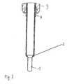
Figur 1- ein Ausführungsbeispiel einer erfindungsgemäßen Glühkerze;
Figur 2- eine
Detailansicht zu Figur 1 ; Figur 3- eine Detailansicht eines weiteren Ausführungsbeispiels;
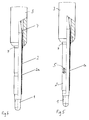
Figur 4- eine schematische Darstellung eines weiteren Ausführungsbeispiels in einer teilweise geschnittenen Ansicht;
Figur 5- eine schematische Darstellung eines weiteren Ausführungsbeispiels in einer teilweise geschnittenen Ansicht;
- Figur 6
- eine schematische Darstellung eines Ausführungsbeispiels in einer Zylinder kopfbohrung eines Motors;
Figur 7- eine Detailansicht zu
Figur 6 .
- FIG. 1
- an embodiment of a glow plug according to the invention;
- FIG. 2
- a detailed view too
FIG. 1 ; - FIG. 3
- a detailed view of another embodiment;
- FIG. 4
- a schematic representation of another embodiment in a partially sectioned view;
- FIG. 5
- a schematic representation of another embodiment in a partially sectioned view;
- FIG. 6
- a schematic representation of an embodiment in a cylinder head bore of an engine;
- FIG. 7
- a detailed view too
FIG. 6 ,
Die Hülse 4 ist in den Kerzenkörper 3 eingepresst. Der Kerzenkörper 3 bildet einen Anschlag, an dem ein Ende der Hülse 4 anliegt. Wie
Die Hülse 4 kann aus dem gleichen Material wie das Schutzrohr 2 gefertigt werden, so dass sich diese Hülse 4 und Schutzrohr 2 leicht verschweißen lassen. Der Kerzenkörper 3 ist bevorzugt aus einem anderen Material, insbesondere aus einem Edelstahl, der sich spanend gut bearbeiten lässt, beispielsweise aus 11 SMnPbBiTe30+C. Der Kerzenkörper 3 kann auf seiner Oberfläche eine Schutzschicht tragen.The
Zwischen dem Schutzrohr 2 und dem Kerzenkörper 3 ist bevorzugt ein Ringspalt, um die Wärmeableitung von dem Glühstift 1 auf den Kerzenkörper 3 zu reduzieren. Bevorzugt ist auch zwischen dem von dem Kerzenkörper 3 umgebenen Abschnitt der Hülse 4 und dem Schutzrohr 2 einen Ringspalt, wie dies in
Die Engstelle 2a kann als eine umlaufende Einschnürung ausgebildet sein, wie dies in
Das Schutzrohr 2 der beschriebenen Ausführungsbeispiele kann eine beschichtete Oberfläche aufweisen. Beispielsweise kann es auf seiner Außenseite eine katalytische Schicht und/oder eine Antihaftschicht tragen. Mit einer katalytischen Schicht, beispielsweise aus einem Platinmaterial, kann das Abbrennen von eventuell vorhandenem Ruß verbessert werden. Mit einer Antihaftschicht, beispielsweise einer Nano-Oberflächenbeschichtung, kann Ablagerungen von Ruß und sonstigen Verbrennungsrückständen entgegengewirkt werden. Im Rohrinneren kann mit einer Oberflächenbeschichtung, insbesondere einer mechanisch weicheren Oberflächenbeschichtung, der Glühstift 1 schwingungsdämpfend abgestützt werden.The
- 11
- GlühstiftGlow plug
- 22
- Schutzrohrthermowell
- 2a2a
- Engstellebottleneck
- 2b2 B
- innerer Randinner edge
- 33
- Kerzenkörperplug body
- 44
- Hülseshell
- 55
- Schlitzeslots
- 66
- 77
- Lötverbindungsolder
- 88th
- Öffnungenopenings
- 99
- Bohrungdrilling
- 1010
- Zylinderkopfcylinder head
Claims (15)
einem keramischen Glühstift (1),
einem den Glühstift (1) umgebenden Schutzrohr (2), und
einem Kerzenkörper (3), aus dem das Schutzrohr (2) herausragt,
dadurch gekennzeichnet, dass
in dem Kerzenkörper (3) eine Hülse (4) steckt, die das Schutzrohr (2) umgibt und mit dem Schutzrohr (2) verschweißt ist.Glow plug with
a ceramic glow plug (1),
a protective tube (2) surrounding the glow plug (1), and
a plug body (3) from which protrudes the protective tube (2),
characterized in that
in the plug body (3) a sleeve (4) inserted, which surrounds the protective tube (2) and is welded to the protective tube (2).
Applications Claiming Priority (1)
| Application Number | Priority Date | Filing Date | Title |
|---|---|---|---|
| DE102009011415A DE102009011415B4 (en) | 2009-03-03 | 2009-03-03 | Ceramic glow plug |
Publications (1)
| Publication Number | Publication Date |
|---|---|
| EP2226561A2 true EP2226561A2 (en) | 2010-09-08 |
Family
ID=42308354
Family Applications (1)
| Application Number | Title | Priority Date | Filing Date |
|---|---|---|---|
| EP10001740A Withdrawn EP2226561A2 (en) | 2009-03-03 | 2010-02-20 | Ceramic glow plug |
Country Status (4)
| Country | Link |
|---|---|
| US (1) | US8513570B2 (en) |
| EP (1) | EP2226561A2 (en) |
| JP (1) | JP2010203763A (en) |
| DE (1) | DE102009011415B4 (en) |
Families Citing this family (8)
| Publication number | Priority date | Publication date | Assignee | Title |
|---|---|---|---|---|
| EP2469169B1 (en) * | 2010-12-22 | 2017-08-16 | HIDRIA AET Druzba za proizvodnjo vzignih sistemov in elektronike d.o.o. | Glow plug with a sleeve to receive the heating rod, equipped with a distal turned-up part |
| DE102011050988B4 (en) | 2011-06-09 | 2016-04-21 | Borgwarner Ludwigsburg Gmbh | glow plug |
| JP5872697B2 (en) * | 2012-08-09 | 2016-03-01 | ボッシュ株式会社 | Glow plug with integrated pressure sensor |
| DE102013112806B4 (en) | 2013-11-20 | 2016-06-23 | Borgwarner Ludwigsburg Gmbh | Method for producing a glow plug |
| DE102016108592B4 (en) * | 2016-05-10 | 2018-06-28 | Borgwarner Ludwigsburg Gmbh | Glow plug and method of manufacturing a glow plug |
| JP6962852B2 (en) * | 2018-04-02 | 2021-11-05 | 日本特殊陶業株式会社 | heater |
| JP7004456B2 (en) * | 2018-04-02 | 2022-01-21 | 日本特殊陶業株式会社 | Heater manufacturing method and heater |
| DE102018108427B3 (en) | 2018-04-10 | 2019-07-25 | Borgwarner Ludwigsburg Gmbh | Heating rod for a glow plug and method for producing a heating rod and glow plug |
Citations (2)
| Publication number | Priority date | Publication date | Assignee | Title |
|---|---|---|---|---|
| DE10029004A1 (en) | 1999-06-16 | 2000-12-28 | Bosch Braking Systems Co | Ceramic heating glow plug for auxiliary diesel engine starter has ceramic heating element with rearmost end closer to attachment element positioned inside metal outer cylinder element |
| DE10322126A1 (en) | 2003-05-16 | 2004-12-02 | Robert Bosch Gmbh | Glow plug with support tube |
Family Cites Families (15)
| Publication number | Priority date | Publication date | Assignee | Title |
|---|---|---|---|---|
| JPS58210412A (en) | 1982-05-31 | 1983-12-07 | Ngk Spark Plug Co Ltd | Ceramic glow plug |
| US5084607A (en) * | 1989-07-28 | 1992-01-28 | Caterpillar Inc. | Interference connection between a heating element and body of a glow plug |
| JP2001165440A (en) * | 1999-12-08 | 2001-06-22 | Ngk Spark Plug Co Ltd | Glow plug and its manufacturing method |
| JP4441136B2 (en) * | 2001-03-16 | 2010-03-31 | 日本特殊陶業株式会社 | Ceramic glow plug and its mounting structure to cylinder head |
| US7281515B2 (en) * | 2000-10-22 | 2007-10-16 | Westport Power Inc. | Method of injecting a gaseous fuel into an internal combustion engine |
| US6727473B2 (en) * | 2001-03-09 | 2004-04-27 | Ngk Spark Plug Co., Ltd. | Ceramic heater device and method for manufacturing the device |
| DE10117641C2 (en) * | 2001-04-09 | 2003-02-27 | Beru Ag | glow plug |
| EP1501335B1 (en) * | 2002-04-26 | 2015-09-23 | NGK Spark Plug Co., Ltd. | Ceramic heater and glow plug having the same |
| CN100398793C (en) * | 2003-04-16 | 2008-07-02 | 韦斯特波特动力股份有限公司 | Internal combustion engine with injection of gaseous fuel |
| EP1612486B1 (en) * | 2004-06-29 | 2015-05-20 | Ngk Spark Plug Co., Ltd | Glow plug |
| JP2006300046A (en) * | 2004-08-05 | 2006-11-02 | Ngk Spark Plug Co Ltd | Glow plug with combustion pressure detecting function |
| DE102005029838B4 (en) | 2005-06-27 | 2019-08-29 | Robert Bosch Gmbh | glow plug |
| DE102006008351A1 (en) * | 2006-02-21 | 2007-08-23 | Robert Bosch Gmbh | Pressure measuring device for arrangement in chamber of internal combustion engine, has housing and ends of sensor cage are connected to force transmission unit and fixing unit |
| DE102006059693A1 (en) * | 2006-12-18 | 2008-06-19 | Robert Bosch Gmbh | Pressure measuring device |
| DE102008009429A1 (en) * | 2007-03-15 | 2008-09-18 | Robert Bosch Gmbh | Seal for a glow plug |
-
2009
- 2009-03-03 DE DE102009011415A patent/DE102009011415B4/en not_active Expired - Fee Related
-
2010
- 2010-02-20 EP EP10001740A patent/EP2226561A2/en not_active Withdrawn
- 2010-03-01 US US12/715,185 patent/US8513570B2/en not_active Expired - Fee Related
- 2010-03-03 JP JP2010046054A patent/JP2010203763A/en not_active Withdrawn
Patent Citations (2)
| Publication number | Priority date | Publication date | Assignee | Title |
|---|---|---|---|---|
| DE10029004A1 (en) | 1999-06-16 | 2000-12-28 | Bosch Braking Systems Co | Ceramic heating glow plug for auxiliary diesel engine starter has ceramic heating element with rearmost end closer to attachment element positioned inside metal outer cylinder element |
| DE10322126A1 (en) | 2003-05-16 | 2004-12-02 | Robert Bosch Gmbh | Glow plug with support tube |
Also Published As
| Publication number | Publication date |
|---|---|
| DE102009011415B4 (en) | 2013-09-26 |
| JP2010203763A (en) | 2010-09-16 |
| US20100224613A1 (en) | 2010-09-09 |
| DE102009011415A1 (en) | 2010-09-09 |
| US8513570B2 (en) | 2013-08-20 |
Similar Documents
| Publication | Publication Date | Title |
|---|---|---|
| EP2226561A2 (en) | Ceramic glow plug | |
| DE60314489T2 (en) | Glow plug and mounting structure for glow plug | |
| DE102007000337B4 (en) | Combustion pressure sensor | |
| DE10112781B4 (en) | Method for producing a glow plug | |
| DE60224741T2 (en) | Glow plug and structure for its attachment to the cylinder head | |
| EP3694684B1 (en) | Spark plug and method for producing a spark plug | |
| DE112009000215T5 (en) | Ground shield with high thread | |
| WO2010060616A2 (en) | Glow plug and method for producing the same | |
| EP3608521B1 (en) | Support pin and catalyst | |
| DE2625318A1 (en) | GLOW PLUGS | |
| DE102005009927B4 (en) | Thermocouple thermocouple with compensating cable | |
| DE112018003168T5 (en) | spark plug | |
| DE102010011739B4 (en) | Spark plug and method of making a spark plug | |
| EP0735323B1 (en) | Glowplug | |
| DE3318458C2 (en) | ||
| EP1188023B1 (en) | Electrically heatable glow plug or glow rod for combustion engines | |
| EP3934033B1 (en) | Pre-chamber spark plug, method for the production of such a pre-chamber spark plug and combustion engine comprising such a pre-chamber spark plug | |
| EP2016653B1 (en) | Ignition coil for an internal combustion engine, in particular of a motor vehicle | |
| DE10154641A1 (en) | Electronically heatable glow plug and method for producing an electrically heatable glow plug | |
| EP3867519B1 (en) | Injector assembly | |
| DE1158778B (en) | Attachment of a metallic corrugated pipe in a metallic connection piece by welding | |
| DE102013112806B4 (en) | Method for producing a glow plug | |
| DE102016121091A1 (en) | Ceramic glow plug | |
| DE102016121346B4 (en) | glow plug | |
| DE102013111922B4 (en) | glow plug |
Legal Events
| Date | Code | Title | Description |
|---|---|---|---|
| PUAI | Public reference made under article 153(3) epc to a published international application that has entered the european phase |
Free format text: ORIGINAL CODE: 0009012 |
|
| AK | Designated contracting states |
Kind code of ref document: A2 Designated state(s): AT BE BG CH CY CZ DE DK EE ES FI FR GB GR HR HU IE IS IT LI LT LU LV MC MK MT NL NO PL PT RO SE SI SK SM TR |
|
| AX | Request for extension of the european patent |
Extension state: AL BA RS |
|
| STAA | Information on the status of an ep patent application or granted ep patent |
Free format text: STATUS: THE APPLICATION HAS BEEN WITHDRAWN |
|
| 18W | Application withdrawn |
Effective date: 20130130 |