EP3608521B1 - Support pin and catalyst - Google Patents
Support pin and catalyst Download PDFInfo
- Publication number
- EP3608521B1 EP3608521B1 EP19190700.5A EP19190700A EP3608521B1 EP 3608521 B1 EP3608521 B1 EP 3608521B1 EP 19190700 A EP19190700 A EP 19190700A EP 3608521 B1 EP3608521 B1 EP 3608521B1
- Authority
- EP
- European Patent Office
- Prior art keywords
- outer sleeve
- pin
- support pin
- support
- sleeve
- Prior art date
- Legal status (The legal status is an assumption and is not a legal conclusion. Google has not performed a legal analysis and makes no representation as to the accuracy of the status listed.)
- Active
Links
- 239000003054 catalyst Substances 0.000 title description 2
- 238000010438 heat treatment Methods 0.000 claims description 40
- 230000003197 catalytic effect Effects 0.000 claims description 33
- 239000000463 material Substances 0.000 claims description 21
- 239000000853 adhesive Substances 0.000 claims description 17
- 230000001070 adhesive effect Effects 0.000 claims description 17
- 239000004020 conductor Substances 0.000 claims description 10
- 239000012811 non-conductive material Substances 0.000 claims description 6
- 239000002253 acid Substances 0.000 claims description 4
- 229910010293 ceramic material Inorganic materials 0.000 claims description 3
- 238000009413 insulation Methods 0.000 claims description 3
- PNEYBMLMFCGWSK-UHFFFAOYSA-N Alumina Chemical compound [O-2].[O-2].[O-2].[Al+3].[Al+3] PNEYBMLMFCGWSK-UHFFFAOYSA-N 0.000 claims 3
- 239000003292 glue Substances 0.000 claims 1
- 230000001681 protective effect Effects 0.000 description 10
- 239000002585 base Substances 0.000 description 8
- 239000000919 ceramic Substances 0.000 description 8
- 238000004519 manufacturing process Methods 0.000 description 8
- TWNQGVIAIRXVLR-UHFFFAOYSA-N oxo(oxoalumanyloxy)alumane Chemical compound O=[Al]O[Al]=O TWNQGVIAIRXVLR-UHFFFAOYSA-N 0.000 description 6
- 238000010292 electrical insulation Methods 0.000 description 5
- 229910018072 Al 2 O 3 Inorganic materials 0.000 description 4
- 239000003637 basic solution Substances 0.000 description 4
- 239000000446 fuel Substances 0.000 description 4
- 239000003779 heat-resistant material Substances 0.000 description 4
- 229910001055 inconels 600 Inorganic materials 0.000 description 4
- 239000000243 solution Substances 0.000 description 4
- 125000006850 spacer group Chemical group 0.000 description 4
- 229910000831 Steel Inorganic materials 0.000 description 3
- 239000012212 insulator Substances 0.000 description 3
- 239000000843 powder Substances 0.000 description 3
- 239000010959 steel Substances 0.000 description 3
- 238000007605 air drying Methods 0.000 description 2
- 229910052782 aluminium Inorganic materials 0.000 description 2
- XAGFODPZIPBFFR-UHFFFAOYSA-N aluminium Chemical compound [Al] XAGFODPZIPBFFR-UHFFFAOYSA-N 0.000 description 2
- 238000010276 construction Methods 0.000 description 2
- 238000001723 curing Methods 0.000 description 2
- 230000007613 environmental effect Effects 0.000 description 2
- 238000013007 heat curing Methods 0.000 description 2
- 229910052751 metal Inorganic materials 0.000 description 2
- 239000002184 metal Substances 0.000 description 2
- 238000000034 method Methods 0.000 description 2
- 239000000203 mixture Substances 0.000 description 2
- 238000012360 testing method Methods 0.000 description 2
- 230000008719 thickening Effects 0.000 description 2
- 238000010521 absorption reaction Methods 0.000 description 1
- 239000004063 acid-resistant material Substances 0.000 description 1
- 150000007513 acids Chemical class 0.000 description 1
- 230000004323 axial length Effects 0.000 description 1
- 239000011230 binding agent Substances 0.000 description 1
- 238000004140 cleaning Methods 0.000 description 1
- 238000002485 combustion reaction Methods 0.000 description 1
- 238000009833 condensation Methods 0.000 description 1
- 230000005494 condensation Effects 0.000 description 1
- 238000002788 crimping Methods 0.000 description 1
- 230000007423 decrease Effects 0.000 description 1
- 230000000694 effects Effects 0.000 description 1
- 238000005516 engineering process Methods 0.000 description 1
- 239000003344 environmental pollutant Substances 0.000 description 1
- 230000002349 favourable effect Effects 0.000 description 1
- 238000011049 filling Methods 0.000 description 1
- 238000002156 mixing Methods 0.000 description 1
- 239000002245 particle Substances 0.000 description 1
- 231100000719 pollutant Toxicity 0.000 description 1
- 238000003825 pressing Methods 0.000 description 1
- 239000007787 solid Substances 0.000 description 1
- XLYOFNOQVPJJNP-UHFFFAOYSA-N water Substances O XLYOFNOQVPJJNP-UHFFFAOYSA-N 0.000 description 1
Images


Classifications
-
- F—MECHANICAL ENGINEERING; LIGHTING; HEATING; WEAPONS; BLASTING
- F01—MACHINES OR ENGINES IN GENERAL; ENGINE PLANTS IN GENERAL; STEAM ENGINES
- F01N—GAS-FLOW SILENCERS OR EXHAUST APPARATUS FOR MACHINES OR ENGINES IN GENERAL; GAS-FLOW SILENCERS OR EXHAUST APPARATUS FOR INTERNAL COMBUSTION ENGINES
- F01N3/00—Exhaust or silencing apparatus having means for purifying, rendering innocuous, or otherwise treating exhaust
- F01N3/08—Exhaust or silencing apparatus having means for purifying, rendering innocuous, or otherwise treating exhaust for rendering innocuous
- F01N3/10—Exhaust or silencing apparatus having means for purifying, rendering innocuous, or otherwise treating exhaust for rendering innocuous by thermal or catalytic conversion of noxious components of exhaust
- F01N3/18—Exhaust or silencing apparatus having means for purifying, rendering innocuous, or otherwise treating exhaust for rendering innocuous by thermal or catalytic conversion of noxious components of exhaust characterised by methods of operation; Control
- F01N3/20—Exhaust or silencing apparatus having means for purifying, rendering innocuous, or otherwise treating exhaust for rendering innocuous by thermal or catalytic conversion of noxious components of exhaust characterised by methods of operation; Control specially adapted for catalytic conversion ; Methods of operation or control of catalytic converters
- F01N3/2006—Periodically heating or cooling catalytic reactors, e.g. at cold starting or overheating
- F01N3/2013—Periodically heating or cooling catalytic reactors, e.g. at cold starting or overheating using electric or magnetic heating means
- F01N3/2026—Periodically heating or cooling catalytic reactors, e.g. at cold starting or overheating using electric or magnetic heating means directly electrifying the catalyst substrate, i.e. heating the electrically conductive catalyst substrate by joule effect
-
- F—MECHANICAL ENGINEERING; LIGHTING; HEATING; WEAPONS; BLASTING
- F01—MACHINES OR ENGINES IN GENERAL; ENGINE PLANTS IN GENERAL; STEAM ENGINES
- F01N—GAS-FLOW SILENCERS OR EXHAUST APPARATUS FOR MACHINES OR ENGINES IN GENERAL; GAS-FLOW SILENCERS OR EXHAUST APPARATUS FOR INTERNAL COMBUSTION ENGINES
- F01N13/00—Exhaust or silencing apparatus characterised by constructional features ; Exhaust or silencing apparatus, or parts thereof, having pertinent characteristics not provided for in, or of interest apart from, groups F01N1/00 - F01N5/00, F01N9/00, F01N11/00
- F01N13/009—Exhaust or silencing apparatus characterised by constructional features ; Exhaust or silencing apparatus, or parts thereof, having pertinent characteristics not provided for in, or of interest apart from, groups F01N1/00 - F01N5/00, F01N9/00, F01N11/00 having two or more separate purifying devices arranged in series
- F01N13/0097—Exhaust or silencing apparatus characterised by constructional features ; Exhaust or silencing apparatus, or parts thereof, having pertinent characteristics not provided for in, or of interest apart from, groups F01N1/00 - F01N5/00, F01N9/00, F01N11/00 having two or more separate purifying devices arranged in series the purifying devices are arranged in a single housing
-
- F—MECHANICAL ENGINEERING; LIGHTING; HEATING; WEAPONS; BLASTING
- F01—MACHINES OR ENGINES IN GENERAL; ENGINE PLANTS IN GENERAL; STEAM ENGINES
- F01N—GAS-FLOW SILENCERS OR EXHAUST APPARATUS FOR MACHINES OR ENGINES IN GENERAL; GAS-FLOW SILENCERS OR EXHAUST APPARATUS FOR INTERNAL COMBUSTION ENGINES
- F01N13/00—Exhaust or silencing apparatus characterised by constructional features ; Exhaust or silencing apparatus, or parts thereof, having pertinent characteristics not provided for in, or of interest apart from, groups F01N1/00 - F01N5/00, F01N9/00, F01N11/00
- F01N13/16—Selection of particular materials
-
- F—MECHANICAL ENGINEERING; LIGHTING; HEATING; WEAPONS; BLASTING
- F01—MACHINES OR ENGINES IN GENERAL; ENGINE PLANTS IN GENERAL; STEAM ENGINES
- F01N—GAS-FLOW SILENCERS OR EXHAUST APPARATUS FOR MACHINES OR ENGINES IN GENERAL; GAS-FLOW SILENCERS OR EXHAUST APPARATUS FOR INTERNAL COMBUSTION ENGINES
- F01N3/00—Exhaust or silencing apparatus having means for purifying, rendering innocuous, or otherwise treating exhaust
- F01N3/08—Exhaust or silencing apparatus having means for purifying, rendering innocuous, or otherwise treating exhaust for rendering innocuous
- F01N3/10—Exhaust or silencing apparatus having means for purifying, rendering innocuous, or otherwise treating exhaust for rendering innocuous by thermal or catalytic conversion of noxious components of exhaust
- F01N3/24—Exhaust or silencing apparatus having means for purifying, rendering innocuous, or otherwise treating exhaust for rendering innocuous by thermal or catalytic conversion of noxious components of exhaust characterised by constructional aspects of converting apparatus
- F01N3/28—Construction of catalytic reactors
- F01N3/2803—Construction of catalytic reactors characterised by structure, by material or by manufacturing of catalyst support
- F01N3/2807—Metal other than sintered metal
- F01N3/281—Metallic honeycomb monoliths made of stacked or rolled sheets, foils or plates
-
- F—MECHANICAL ENGINEERING; LIGHTING; HEATING; WEAPONS; BLASTING
- F01—MACHINES OR ENGINES IN GENERAL; ENGINE PLANTS IN GENERAL; STEAM ENGINES
- F01N—GAS-FLOW SILENCERS OR EXHAUST APPARATUS FOR MACHINES OR ENGINES IN GENERAL; GAS-FLOW SILENCERS OR EXHAUST APPARATUS FOR INTERNAL COMBUSTION ENGINES
- F01N3/00—Exhaust or silencing apparatus having means for purifying, rendering innocuous, or otherwise treating exhaust
- F01N3/08—Exhaust or silencing apparatus having means for purifying, rendering innocuous, or otherwise treating exhaust for rendering innocuous
- F01N3/10—Exhaust or silencing apparatus having means for purifying, rendering innocuous, or otherwise treating exhaust for rendering innocuous by thermal or catalytic conversion of noxious components of exhaust
- F01N3/24—Exhaust or silencing apparatus having means for purifying, rendering innocuous, or otherwise treating exhaust for rendering innocuous by thermal or catalytic conversion of noxious components of exhaust characterised by constructional aspects of converting apparatus
- F01N3/28—Construction of catalytic reactors
- F01N3/2839—Arrangements for mounting catalyst support in housing, e.g. with means for compensating thermal expansion or vibration
- F01N3/2842—Arrangements for mounting catalyst support in housing, e.g. with means for compensating thermal expansion or vibration specially adapted for monolithic supports, e.g. of honeycomb type
-
- F—MECHANICAL ENGINEERING; LIGHTING; HEATING; WEAPONS; BLASTING
- F01—MACHINES OR ENGINES IN GENERAL; ENGINE PLANTS IN GENERAL; STEAM ENGINES
- F01N—GAS-FLOW SILENCERS OR EXHAUST APPARATUS FOR MACHINES OR ENGINES IN GENERAL; GAS-FLOW SILENCERS OR EXHAUST APPARATUS FOR INTERNAL COMBUSTION ENGINES
- F01N2330/00—Structure of catalyst support or particle filter
- F01N2330/02—Metallic plates or honeycombs, e.g. superposed or rolled-up corrugated or otherwise deformed sheet metal
-
- Y—GENERAL TAGGING OF NEW TECHNOLOGICAL DEVELOPMENTS; GENERAL TAGGING OF CROSS-SECTIONAL TECHNOLOGIES SPANNING OVER SEVERAL SECTIONS OF THE IPC; TECHNICAL SUBJECTS COVERED BY FORMER USPC CROSS-REFERENCE ART COLLECTIONS [XRACs] AND DIGESTS
- Y02—TECHNOLOGIES OR APPLICATIONS FOR MITIGATION OR ADAPTATION AGAINST CLIMATE CHANGE
- Y02T—CLIMATE CHANGE MITIGATION TECHNOLOGIES RELATED TO TRANSPORTATION
- Y02T10/00—Road transport of goods or passengers
- Y02T10/10—Internal combustion engine [ICE] based vehicles
- Y02T10/12—Improving ICE efficiencies
Definitions
- the invention relates to a support pin according to the preamble of claim 1. It also relates to a catalytic converter.
- the electrically heated catalytic converter offers the alternative solution in the modern exhaust gas cleaning of internal combustion engines.
- a heating disk is placed in front of the catalytic converter element in order to ensure that the catalytic converter works as soon as the engine is started.
- this solution is also used effectively for the "sailing" and "start / stop” functions.
- all limit values of Euro 6d have already been undercut.
- Our solution described below is to mount this heating disk in front of the catalytic converter element in the catalytic converter housing.
- the electrical insulation, the holding force and the resistance to water, fuel and AdBlue are decisive.
- the currently used heating conductor supports are made from a heating cable.
- This line consists of an inner wire made of steel and an outer sheath made of steel and an insulator layer between the two electrically conductive steel parts.
- the insulator layer consists of broken and re-solidified ceramic. The outer sheath is partially twisted off mechanically, the broken ceramic falls off in this area and the inner conductor is thus exposed.
- a support pin for an electrically heatable honeycomb body is known. This has a core made of ceramic, electrically non-conductive material.
- the conditions of use in the catalytic converter are high temperature differences, vibrations, but also high fluctuations in humidity as a result of condensation and unburned fuel and AdBlue. Since the currently used ceramic layer is accessible from both sides, moisture penetrates unhindered. When the heat (temperature) rises rapidly, which is caused by the integrated heating at every start, the moisture that has penetrated is evaporated, and the resulting expansion in volume detaches the smallest particles of the remaining insulator layer. After a short time, the currently used ceramic layer is destroyed to such an extent that the electrical insulation is inevitably no longer provided and a short circuit occurs. As a result, the function of the heating is no longer guaranteed in continuous operation.
- the invention is therefore based on the object of improving a support pin in such a way that it can be used safely in continuous operation. Furthermore, a catalytic converter is to be provided which enables safe use in continuous operation.
- the invention is based on the consideration that a support pin, when used in a catalytic converter, is exposed to a variety of loads and must meet various requirements at the same time.
- the radiator must be reliable in front of the honeycomb body of the catalytic converter, this bracket must function reliably in continuous operation.
- the support pins used for this bracket have to withstand the heat conditions permanently and withstand influences such as moisture and AdBlue. In addition, they must provide reliable electrical insulation of the heating element from the carrier of the catalytic converter.
- the respective support pin comprises an outer sleeve and a pin body, the two parts being electrically isolated from one another by an electrically non-conductive inner sleeve which surrounds the pin body within the outer sleeve.
- electrically non-conductive preferably corresponds to an electrical conductivity of less than 10-8 S ⁇ cm-1.
- the outer sleeve and / or the pin body are advantageously made of solderable and / or weldable material.
- the solderability allows the outer sleeve to be soldered to the heating element and the pin body to the carrier body of the catalytic converter.
- the outer sleeve and the pin body are thus preferably each made of electrically conductive or electrically conductive material. In a similar way, the two components can be welded to the radiator / carrier body.
- the material of the inner sleeve is advantageously heat-resistant and / or acid-resistant.
- heat-resistant preferably includes heat resistance at temperatures greater than or equal to 600.degree.
- the acid resistance preferably relates to the acids occurring in the catalytic converter in the respective fuel (petrol / diesel) and AdBlue.
- the material of the inner sleeve is preferably a ceramic material, in particular aluminum oxide. This material does not absorb moisture and is resistant to AdBlue and any fuel.
- the support pin is suitable for use in catalytic converters in both diesel and gasoline engines or Otto engines.
- the outer sleeve is preferably designed to be radially symmetrical at least in some areas, the pin body being arranged centrally within the outer sleeve.
- the outer sleeve preferably has an open and a closed end, the pin body protruding axially from the outer sleeve at the open end. In the installed state, the closed end faces the radiator or is attached to it, in particular soldered.
- An outer sleeve that is closed on this side has the advantage that components inside the outer sleeve, in particular the inner sleeve, are protected from external influences in the catalytic converter, in particular AdBlue.
- the outer sleeve preferably has a first open end and a second open end, the pin body protruding axially from the outer sleeve at the second open end.
- the design with two open ends is simpler and cheaper in terms of production technology. It can be used in particular if the material of the inner sleeve is AdBlue-resistant.
- the outer sleeve preferably has an annular end region at the open end at which the pin body protrudes from the outer sleeve, which blocks the inner sleeve in the axial direction or prevents the movement of the inner sleeve in the axial direction.
- the annular end area is preferably realized by flanging the outer sleeve in this area.
- the annular end region preferably comprises an annular region which is perpendicular to the essentially cylindrical part of the outer sleeve. In this way, the surface of this annular area prevents the inner sleeve from moving in the direction of the open end of the outer sleeve at which the pin body protrudes.
- an insulating element made of electrically non-conductive material is advantageously arranged between the first open end of the outer sleeve and the pin body. In this way, the insulating effect between the outer sleeve and the pin body partially arranged in it is increased.
- the insulating element is preferably made of a heat-resistant material.
- the insulating element is preferably disk-shaped or spherical or cylindrical.
- a protective element is preferably arranged in the axial direction between a first open end of the outer sleeve and the insulating element.
- the protective element serves to protect the insulating element during the manufacture of the support pin.
- the outer sleeve is preferably initially provided in a cylindrical shape. After inserting the pin, inner sleeve and insulating element, it is bent over on both sides by a crimping process so that the inner components are prevented from moving axially.
- the protective element is provided. In this way, the kink of the outer sleeve adjoins the protective element and not the insulating element.
- the pen body has a thickened area in which the pen body has a cross section that is larger than an inner cross section of the inner sleeve, the inner sleeve being arranged in the axial direction between this thickened area and one end of the outer sleeve at which the pen body protrudes from the outer sleeve is.
- the pen body has a radius in this thickened area which is larger than the radius of the adjacent inner sleeve.
- the inner sleeve is prevented from moving axially by the end region, and the inner sleeve prevents the pin body from moving axially in this direction because of the thickened region.
- an adhesive which in a preferred embodiment is described below, is applied between the thickened area and the inside of the outer sleeve, which adhesive bonds the outer sleeve and the pen body to one another. In this way, anti-twist protection is achieved, ie the pen body cannot rotate with respect to the outer sleeve. This prevents the heater from loosening due to vibrations of the honeycomb body or heating body, which can lead to material damage and insufficient heating of the carrier body or honeycomb body.
- the pin body advantageously has a radially enlarged area, in particular a collar / base.
- the collar is supported in the axial direction on the inner sleeve and on the opposite side on the insulating element or, if there is no insulating element, on the inside of the outer sleeve.
- the collar preferably corresponds to a thickened area described above, which is arranged at one end of the pen body.
- the pen body is rotated from a piece of metal with a larger diameter.
- the collar / base and the remaining part of the pin body are then constructed in one piece or are a piece of metal, in particular made of the material 2.4869 (NiCr8020).
- the base is a separate part which is attached to the essentially cylindrical part of the pen body or is fastened to this part by deformation, in particular by means of a pressing device.
- two spaced apart inner sleeves are provided.
- the thickened area is advantageously arranged between the two inner sleeves.
- the pin body preferably has knurling at least in some areas in the axial direction between the two inner sleeves.
- the knurling serves as a stop for the inner sleeve.
- the two inner sleeves are pushed onto the pen body from opposite sides.
- a ring for example made of electrically conductive material, is advantageously arranged axially in each case in the area between an inner sleeve and the knurling. These rings can reduce the risk of the pin body slipping in the outer sleeve or increase the resistance to pull-off forces.
- the pin body preferably tapers at its end which protrudes from the outer sleeve, at least in some areas, in particular conically.
- Both the heating body and the carrier body can be designed as honeycomb bodies.
- the outer sleeve of the support pin can in particular be connected to the heating element by means of a soldered connection.
- the heating element is preferably designed as a heating disk.
- the pin is preferably connected to the carrier body by means of a soldered connection.
- the heating element is preferably fastened to the carrier body only by means of a multiplicity of support pins and without further fastening elements. For example, between 50 and 150 support pins can be used for this purpose.
- the advantages of the invention are, in particular, that by providing a support pin, which has a very long service life due to its construction, it can be ensured that the function of the catalytic converter does not decline. In this way, permanent low pollutant emissions can be guaranteed.
- the support pin can perform its function throughout the life of the catalytic converter.
- Support pin 2 shown in a longitudinal section comprises an essentially cylindrical outer sleeve 6 and a pin body 10 which is inserted into outer sleeve 6.
- the pin body 10 is partially surrounded by an inner sleeve 14.
- the outer sleeve 6 has a first end 20 and a second end 22, at which the pin body 10 protrudes from the outer sleeve 6.
- the pin body 10 which is essentially cylindrical in shape or is essentially, ie, designed to be radially symmetrical over a large part of its length, has a collar or base 30 at a first end 24, which is arranged inside the outer sleeve 6, which is formed as a radially enlarged end region of the pin body 10 and is preferably designed in a cylindrical shape.
- the pen body 10 tapers, preferably conically.
- the base 30 is a special case of one in connection with the FIG. 14th and 15th described thickening area 120 of the pen body 10.
- the outer sleeve 6 and the pin body 10 are each made of solderable or solderable material or made of electrically conductive or electrically conductive material.
- the pin body 10 is made of the material 2.4869 (NiCr8020).
- the outer sleeve 6 is made, for example, from 2.4816 (Inconel 600) or from NiCr15Fe.
- the outer sleeve 6 is preferably connected to a heating body, in particular a heating disk, and the end 26 of the support pin is connected to a catalytic converter element or carrier body, in particular a honeycomb body, of the catalytic converter.
- a heating body in particular a heating disk
- the end 26 of the support pin is connected to a catalytic converter element or carrier body, in particular a honeycomb body, of the catalytic converter.
- An electric current flows in both components (support body and heating element) while the catalytic converter is operating, so it is extremely important to avoid a short circuit between these two components. Therefore, outer sleeve 6 and pin body 10 must be electrically and reliably isolated from one another.
- an inner sleeve 14 is provided for this purpose, which surrounds the pen body 10 within the outer sleeve 6 in regions, ie over a certain length in the axial direction of the pen body 10.
- the inner sleeve 14 lies radially outward from a central axis 10a of the pin body 10 thus in the radial direction between the pin body 10 and the outer sleeve 6.
- the outer sleeve 6 has an annular end region 48.
- the inner sleeve 14 is made of electrically non-conductive or electrically non-conductive, heat-resistant and acid-resistant material. It is preferably made of aluminum oxide (Al 2 O 3 ).
- a cylindrical or disk-shaped insulating element 40 is arranged within the outer sleeve 6, which is used for the electrical insulation of the outer sleeve 6 and the pin body 10.
- the insulating element 40 is made of electrically non-conductive or electrically non-conductive and heat-resistant material.
- the material of the inner sleeve 14 and / or the material of the insulating element 40 is preferably a dielectric. Suitable materials are, for example, 1.4122 (X39CrMo17-1) or 1.4113 (X6CrMo17-1).
- An annular gap 44 is formed between the base 30 and the aluminum sleeve 6.
- the distance between each electrically conductive component is chosen so large that an insulation value of more than 20 M ⁇ is achieved.
- the pen body 10 preferably has a length between 34 and 36 mm, in particular 35 mm and a diameter between 1.1 and 1.3 mm, in particular 1.2 mm.
- the outer sleeve 6 preferably has a diameter between 2.3 and 2.5 mm, in particular 2.4 mm. These are advantageous example dimensions for all of the illustrated embodiments.
- the outer sleeve 6 preferably has a length which is between a quarter and a third of the length of the pen body 10.
- the support pin 2 is preferably assembled as follows.
- the outer sleeve 6 is provided in a cylindrical shape.
- the inner sleeve 14 is pushed onto the pen body 10.
- the outer sleeve 6 is now beaded at the edge in the area of the second end 22, so that the annular end area 48 is created.
- the insulating element 40 is now pushed into the outer sleeve at the end 20 of the outer sleeve 6, until it rests on the base 30.
- the outer sleeve 6 is then crimped at the edge in the end region 20, so that the annular edge region 34 is created.
- FIG. 2 A support pin 2 in a second preferred embodiment is shown in FIG FIG. 2 shown.
- This embodiment differs from that in FIG. 1 embodiment shown in that at the end 20 of the outer sleeve 6 in the outer sleeve between the end region 34 and insulating element 40, a protective element 52, which consists of heat-resistant material (greater than or equal to 600 ° C.), is arranged.
- the protective element 52 serves to protect the insulating element 40 from damage during the flanging of the outer sleeve 6 in the end region 20.
- the protective element 52 is made, for example, from the material 2.4816 (Inconel 600).
- the protective element 52 is convex at its end facing away from the insulating element 40.
- the two in the FIG. 1 and 2 The embodiments shown have an open end region 20 of the outer sleeve 6, which is more favorable in terms of material compared to a closed region and is easier to manufacture.
- This embodiment is preferred if the material of the inner sleeve 14 is resistant or insensitive to environmental influences in the catalytic converter, in particular AdBlue.
- FIG. 3 a further preferred embodiment of a support pin 2 is shown.
- This version differs from the one in FIG. 1
- the embodiment shown in that the outer sleeve 6 has a rounded or convex and closed end area 60 in its end area 20. Since the outer sleeve 6 is closed in this area, the inner sleeve 14 is protected from environmental influences such as AdBlue.
- the insulating element 40 is present Configured spherically with an outer curvature which corresponds to the inner curvature of the end region 60. In this way, stable mounting of the insulating element 40 is made possible.
- FIG. 4th Another preferred embodiment of a support pin 2 differs from that in FIG. 3
- the embodiment shown in that the outer sleeve 6 has a convex, open end area 64 in the end area 20, whereby the production compared to the in FIG. 3 version shown is simplified.
- the construction of the outer sleeve 6, which is closed on one side, has to be machined or machined for its production as a deep-drawn part or as a sleeve that is drilled.
- a tube can be used for its manufacture, which is cut to length, so that this design is more cost-effective to manufacture.
- FIG. 5 Another preferred embodiment of a support pin 2 is shown, which has an outer sleeve 6 with a closed rounded end region 60.
- two inner sleeves 14a, 14b are provided which surround the pin body 10 within the outer sleeve 6 like a sleeve.
- the materials described above in connection with an individual inner sleeve 14 are preferably used as the material of the inner sleeves 14a, 14b.
- the pin body 10 does not have a base 30, but rather a knurling 72, which in each case forms a stop for an inner sleeve 14a, 14b.
- the inner sleeve 14a, 14b is pushed onto the pin body 10 from one side (from the left and from the right) until the inner sleeve 14a, 14b hits the knurling.
- the pin body 10 with the mounted inner sleeves 14a, 14b is inserted into the outer sleeve 6 up to the stop. Depending on the open or closed design of the outer sleeve 6, this is then crimped on the respective open side.
- FIG. 6th a further preferred embodiment of a support pin 2 is shown.
- the knurling 72 has a smaller extent in the axial direction.
- Rings 76, 78 made of electrically conductive material, which are made in particular from 2.4816 (Inconel 600), are arranged on both edges of the knurling 72.
- the rings 76, 78 improve the stability of the support pin 2 against pulling forces or against slipping of the pin body 10 against the outer sleeve 6. They also prevent damage to the inner sleeves 14a, 14b by the knurling 72.
- the rings 76, 78 serve as protection for the Ceramic material of the respective inner sleeve, as the ceramic is very brittle.
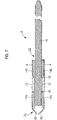
- FIG. 7th a further preferred embodiment of a support pin 2 is shown.
- This variant differs from the one in the FIG. 6th
- the embodiment shown in that the outer sleeve 6 is designed to be open in the end region 20.
- An end region 82 of the outer sleeve 6 is bent or flanged, this region 82 having an angle of less than 90 ° to the cylindrical part of the outer sleeve 6.
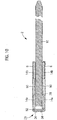
- FIG. 8th Another preferred embodiment of a support pin 2 is shown in FIG FIG. 8th shown.
- the outer sleeve 6 in this example has a closed, convex and rounded end region 60.
- the pen body 10 has no knurling 72.
- an intermediate sleeve 90 is arranged between them in the axial direction, which is laser-welded to the pin or pin body 10 and which is made of electrically conductive material, in particular 2.4816 (Inconel 600).
- the intermediate sleeve 90 forms a thickened area 120, as is described further below. This enables the inner sleeves 14a, 14b to be spaced apart in a particularly reliable manner and prevents the pin body 10, outer sleeve 6 and inner sleeves 14a, 14b from slipping axially with respect to one another.
- FIG. 9 The preferred variant of a support pin 2 shown differs from that in FIG. 8th illustrated embodiment by an open end region 82.
- FIG. 10 illustrated preferred embodiment of a support pin 2 differs from that in FIG. 9 shown variant by a protective element 52 arranged at the end 20 within the outer sleeve 6 (cf. FIG. 2 ).
- the protective element 52 protects the material of the inner sleeve 14a during the production process during the flanging of the end region 34 of the outer sleeve 6.
- FIG. 11 Another preferred embodiment of the support pin 2 is shown in FIG. 11 shown.
- This variant differs from the one in FIG. 10
- the illustrated embodiment takes place by means of a knurling 72 and two rings 76, 78.
- a catalytic converter 100 is shown schematically.
- This has a carrier body 104, which is preferably designed as a honeycomb body, and a heating body 106, which can also have a honeycomb-like structure.
- the heating element 106 is formed as a heating conductor or as a heating disk. The efficiency of the catalytic converter is significantly increased by the heating element 106, which an exhaust gas stream 110 hits first and which is used for additional heating of the carrier body.
- a plurality of support pins 2 described above and below are provided, of which only three support pins are shown for the sake of clarity.
- the respective outer sleeve is attached to the heating disk, in particular at least partially inserted into it and soldered.
- the respective pin body 10 is fastened to the carrier body 104, in particular at least partially inserted into it and soldered.
- FIG. 13th is a plan view of a heating disk 106 shown with a heating conductor support by a plurality of support pins 2.
- the outer sleeves 6 of the support pins 2 are soldered to the heating disk 106.
- a support pin 2 is shown in an embodiment according to the invention with a pin body 10 and two inner sleeves 14a, 14b.
- the pen body 10 has a thickened area 120, the radius or cross section of which is greater than the radius or cross section of an inner sleeve 14b, which is arranged between the thickened area 120 and end area 48 of the outer sleeve.
- the thickened area 120 is designed over an axial length I with the same radius.
- the pen body 10 is advantageously turned out of a component with a diameter that is equal to or greater than the largest existing diameter of the pen body 10. When unscrewing, the radius for creating the thickened area 120 is kept correspondingly large.
- the pen body 10 is made in one piece in this way.
- a ring-like or sleeve-like air gap 124 or area is implemented between the thickened area 120 and the inside of the outer sleeve 6, viewed radially.
- the radial expansion of the air gap is dimensioned in such a way that no spark discharge can take place with the voltages occurring during operation.
- the support pin 2 is manufactured as in FIG. 14th , but does not have the inner sleeve 14a, which is arranged adjacent to the closed end 20 of the outer sleeve.
- the thickening area 120 is here to a certain extent a collar 30 (see FIG. 1 ).
- FIG. 15th a further preferred embodiment of a support pin 2 is shown. This embodiment differs from the embodiment according to FIG. 14th in that the air gap 124 is filled with an adhesive 126. The adhesive bonds the pen body 10 to the outer sleeve 6. This prevents the pen body 10 from rotating in relation to the outer sleeve 6.
- the stick body 10 is preferably also bonded to the inner sleeves 14a, 14b or the inner sleeves 14a, 14b to the outer sleeve 6, ie. H. the adhesive is preferably introduced in such a way that these parts are also bonded, whereby the anti-twist protection is further strengthened.
- FIGS FIG. 1-13 illustrated embodiments Further preferred embodiments of a support pin 2 correspond to those in FIGS FIG. 1-13 illustrated embodiments, wherein in each case in an annular or sleeve-shaped area between outer sleeve 6 and pin body 10 adhesive is introduced so that pin body 10 and outer sleeve 6 are at least partially glued to one another.
- a basic solution is preferably used as the adhesive.
- Particularly suitable adhesives or basic solutions are "Ceramabind 643" or “Ceramabind 642", which are offered by Kager GmbH Industrie effort.
- the adhesive is applied to the pen body 10 in the thickened area or, with the pen body 10 inserted in the outer sleeve 6, the adhesive is introduced into the annular gap between the pin body 10 and the outer sleeve 6. Air drying is then carried out for preferably at least one hour. This is followed by at least one heat curing and / or final curing, temperatures of 95 ° C. and above preferably being used.
- the adhesive is preferably produced as follows: A powder of Al 2 O 3 is mixed into a basic solution that is highly compatible with the powder until a constant viscosity is achieved. It is mixed slowly to reduce air bubbles. A mixing ratio of binder: powder between 4: 1 and 1: 1 (parts by weight) is used.
- the mixture is then applied to the pen body 10 in the thickened area or, with the pen body 10 inserted in the outer sleeve, the mixture is introduced into the annular gap between the pin body 10 and the outer sleeve 6.
- Air drying is then carried out for preferably at least one hour. This is followed by at least one heat curing and / or final curing, temperatures of 95 ° C. and above preferably being used.
- These parts made of aluminum oxide serve as spacers between the heating element 106 and the carrier body 104 and are intended to electrically separate these two elements from one another.
- the invention thus also relates to an arrangement of a heating element 106 and a support body 104, which are spaced apart by means of at least one spacer element made of aluminum oxide (Al 2 O 3 ), the respective spacer element at one end with the heating element 106 and at another end with the Carrier body 104 is glued, the above-mentioned adhesive preferably being used.
- the spacer element is preferably designed as a pin.
Description
Die Erfindung betrifft einen Stützstift nach dem Oberbegriff von Anspruch 1. Sie betrifft weiterhin einen Katalysator.The invention relates to a support pin according to the preamble of claim 1. It also relates to a catalytic converter.
Der elektrisch heizbare Katalysator bietet die alternative Lösung in der modernen Abgasreinigung von Verbrennungsmotoren. Hierbei wird eine Heizscheibe vor dem Katalysatorelement platziert, um die Wirkungsweise des Katalysators bereits in der Startphase des Motors sicherzustellen. Bei heutigen modernen Fahrzeugen kommt diese Lösung zusätzlich bei den Funktionen "Segeln" und "Start Stopp" wirkungsvoll zum Einsatz. In Testaufbauten wurden bereits alle Grenzwerte der Euro 6d unterboten. Unsere nachfolgend beschriebene Lösung ist die Halterung dieser Heizscheibe vor dem Katalysatorelement im Katalysatorgehäuse. Hierbei sind die elektrische Isolation, die Haltekraft und die Beständigkeit gegenüber Wasser, Kraftstoff und AdBlue entscheidend.The electrically heated catalytic converter offers the alternative solution in the modern exhaust gas cleaning of internal combustion engines. A heating disk is placed in front of the catalytic converter element in order to ensure that the catalytic converter works as soon as the engine is started. In today's modern vehicles, this solution is also used effectively for the "sailing" and "start / stop" functions. In test setups, all limit values of Euro 6d have already been undercut. Our solution described below is to mount this heating disk in front of the catalytic converter element in the catalytic converter housing. Here, the electrical insulation, the holding force and the resistance to water, fuel and AdBlue are decisive.
Die derzeit eingesetzten Heizleiterabstützungen werden aus einer Heizleitung hergestellt. Diese Leitung besteht aus einem Innendraht aus Stahl sowie einem Außenmantel aus Stahl und einer Isolator Schicht zwischen den beiden elektrisch leitenden Stahlteilen. Die Isolator Schicht besteht aus gebrochener und erneut verfestigter Keramik. Der Außenmantel wird teilweise mechanisch abgedreht, die gebrochene Keramik fällt in diesem Teilbereich ab und der Innenleiter ist somit freigelegt.The currently used heating conductor supports are made from a heating cable. This line consists of an inner wire made of steel and an outer sheath made of steel and an insulator layer between the two electrically conductive steel parts. The insulator layer consists of broken and re-solidified ceramic. The outer sheath is partially twisted off mechanically, the broken ceramic falls off in this area and the inner conductor is thus exposed.
Aus der
Aus der
Als weiterer Stand der Technik wird auf
Die Einsatzbedingungen im Katalysator sind hohe Temperaturunterschiede, Vibrationen, aber auch hohe Schwankungen der Feuchtigkeit infolge von Kondenswasser und nicht verbranntem Kraftstoff sowie zugeführtem AdBlue. Da die derzeitig eingesetzte Keramikschicht von beiden Seiten zugängig ist, dringt Feuchtigkeit ungehindert ein. Bei schnell ansteigender Hitze (Temperatur), welche durch die integrierte Heizung bei jedem Start entsteht, wird die eingedrungene Feuchtigkeit verdampft, in der daraus resultierenden Volumenausdehnung werden kleinste Partikel der verbliebenen Isolatorschicht herausgelöst. Nach kurzer Zeit ist die derzeit eingesetzte Keramikschicht soweit zerstört, dass die elektrische Isolation zwangsläufig nicht mehr gegeben ist und es zu einem Kurzschluss kommt. Dadurch ist die Funktion der Heizung im Dauerbetrieb nicht mehr gewährleistet.The conditions of use in the catalytic converter are high temperature differences, vibrations, but also high fluctuations in humidity as a result of condensation and unburned fuel and AdBlue. Since the currently used ceramic layer is accessible from both sides, moisture penetrates unhindered. When the heat (temperature) rises rapidly, which is caused by the integrated heating at every start, the moisture that has penetrated is evaporated, and the resulting expansion in volume detaches the smallest particles of the remaining insulator layer. After a short time, the currently used ceramic layer is destroyed to such an extent that the electrical insulation is inevitably no longer provided and a short circuit occurs. As a result, the function of the heating is no longer guaranteed in continuous operation.
Der Erfindung liegt daher die Aufgabe zugrunde, einen Stützstift dahingehend zu verbessern, dass ein sicherer Einsatz im Dauerbetrieb gewährleistet wird. Weiterhin soll ein Katalysator bereitgestellt werden, der sichere Einsätze im Dauerbetrieb ermöglicht.The invention is therefore based on the object of improving a support pin in such a way that it can be used safely in continuous operation. Furthermore, a catalytic converter is to be provided which enables safe use in continuous operation.
In Bezug auf den Stützstift wird diese Aufgabe erfindungsgemäß gelöst mit einem Stützstift mit den Merlkmalen des Anspruchs 1.With regard to the support pin, this object is achieved according to the invention with a support pin having the features of claim 1.
Vorteilhafte Ausgestaltungen der Erfindung sind Gegenstand der Unteransprüche und der Beschreibung.Advantageous refinements of the invention are the subject matter of the subclaims and the description.
Die Erfindung geht von der Überlegung aus, dass ein Stützstift im Einsatz in einem Katalysator vielfältigen Belastungen ausgesetzt ist und verschiedene Anforderungen gleichzeitig erfüllen muss. Der Heizkörper muss zuverlässig vor dem Wabenkörper des Katalysators gehalten werden, diese Halterung muss im Dauerbetrieb zuverlässig funktionieren. Gleichzeitig müssen die für diese Halterung verwendeten Stützstifte den Hitzebedingungen dauerhaft standhalten, und Einflüssen wie Feuchtigkeit und AdBlue standhalten. Darüber hinaus müssen sie eine zuverlässige elektrische Isolierung des Heizkörpers von dem Trägerkörper des Katalysators bereitstellen.The invention is based on the consideration that a support pin, when used in a catalytic converter, is exposed to a variety of loads and must meet various requirements at the same time. The radiator must be reliable in front of the honeycomb body of the catalytic converter, this bracket must function reliably in continuous operation. At the same time, the support pins used for this bracket have to withstand the heat conditions permanently and withstand influences such as moisture and AdBlue. In addition, they must provide reliable electrical insulation of the heating element from the carrier of the catalytic converter.
Wie nunmehr erkannt wurde, lässt sich ein zuverlässiger Einsatz der Stützstifte erreichen, indem der jeweilige Stützstift eine Außenhülse und einen Stiftkörper umfasst, wobei die beiden Teile durch eine elektrisch nicht-leitfähige Innenhülse, die den Stiftkörper innerhalb der Außenhülse umgibt, voneinander elektrisch isoliert werden. Auf diese Weise kann eine gegenüber den speziellen Bedingungen im Katalysator robuste Ausführung eines Stützstiftes bereitgestellt werden, mit der ein Kurzschluss ausgeschlossen werden kann.As has now been recognized, a reliable use of the support pins can be achieved in that the respective support pin comprises an outer sleeve and a pin body, the two parts being electrically isolated from one another by an electrically non-conductive inner sleeve which surrounds the pin body within the outer sleeve. In this way it is possible to provide a support pin which is robust in relation to the special conditions in the catalytic converter and with which a short circuit can be excluded.
Der Begriff "elektrisch nicht leitend" korrespondiert bevorzugt zu einer elektrischen Leitfähigkeit von weniger als 10-8 S·cm-1.The term “electrically non-conductive” preferably corresponds to an electrical conductivity of less than 10-8 S · cm-1.
Die Außenhülse und/oder der Stiftkörper sind vorteilhafterweise aus lötbarem und/oder schweißbarem Material hergestellt. Die Lötbarkeit erlaubt das Verlöten der Außenhülse mit dem Heizkörper und des Stiftkörpers mit dem Trägerkörper des Katalysators. Außenhülse und Stiftkörper sind somit bevorzugt jeweils aus elektrisch leitfähigen bzw. elektrisch leitendem Material hergestellt. In ähnlicher Weise können die beiden Komponenten mit Heizkörper/Trägerkörper verschweißt werden.The outer sleeve and / or the pin body are advantageously made of solderable and / or weldable material. The solderability allows the outer sleeve to be soldered to the heating element and the pin body to the carrier body of the catalytic converter. The outer sleeve and the pin body are thus preferably each made of electrically conductive or electrically conductive material. In a similar way, the two components can be welded to the radiator / carrier body.
Vorteilhafterweise ist das Material der Innenhülse hitzebeständig und/oder säurebeständig. Der Begriff "hitzebeständig" umfasst bevorzugt eine Hitzebeständigkeit bei Temperaturen größer oder gleich 600 °C. Die Säurebeständigkeit bezieht sich bevorzugt auf die im Katalysator auftretenden Säuren im jeweiligen Kraftstoff (Benzin/Diesel) sowie AdBlue.The material of the inner sleeve is advantageously heat-resistant and / or acid-resistant. The term “heat-resistant” preferably includes heat resistance at temperatures greater than or equal to 600.degree. The acid resistance preferably relates to the acids occurring in the catalytic converter in the respective fuel (petrol / diesel) and AdBlue.
Bevorzugt ist das Material der Innenhülse ein Keramik-Werkstoff, insbesondere Aluminiumoxid. Dieses Material nimmt keine Feuchtigkeit auf und ist beständig gegenüber AdBlue und jeglichem Kraftstoff.The material of the inner sleeve is preferably a ceramic material, in particular aluminum oxide. This material does not absorb moisture and is resistant to AdBlue and any fuel.
Der Stützstift ist geeignet, in Katalysatoren von Diesel- als auch Benzinmotoren bzw. Otto-Motoren eingesetzt zu werden.The support pin is suitable for use in catalytic converters in both diesel and gasoline engines or Otto engines.
Die Außenhülse ist bevorzugt zumindest bereichsweise radialsymmetrisch ausgebildet, wobei der Stiftkörper mittig innerhalb der Außenhülse angeordnet ist.The outer sleeve is preferably designed to be radially symmetrical at least in some areas, the pin body being arranged centrally within the outer sleeve.
Die Außenhülse weist bevorzugt ein offenes und ein geschlossenes Ende auf, wobei der Stiftkörper axial am offenen Ende aus der Außenhülse hinausragt. Das geschlossene Ende ist dabei im verbauten Zustand dem Heizkörper zugewandt bzw. an ihm befestigt, insbesondere verlötet. Eine auf dieser Seite geschlossene Außenhülse hat den Vorteil, dass Komponenten im Inneren der Außenhülse, insbesondere die Innenhülse, vor äußeren Einflüssen im Katalysator, insbesondere AdBlue, geschützt werden.The outer sleeve preferably has an open and a closed end, the pin body protruding axially from the outer sleeve at the open end. In the installed state, the closed end faces the radiator or is attached to it, in particular soldered. An outer sleeve that is closed on this side has the advantage that components inside the outer sleeve, in particular the inner sleeve, are protected from external influences in the catalytic converter, in particular AdBlue.
Die Außenhülse weist bevorzugt ein erstes offenes Ende auf und ein zweites offenes Ende auf, wobei der Stiftkörper axial am zweiten offenen Ende aus der Außenhülse herausragt. Die Ausführung mit zwei offenen Enden ist fertigungstechnisch einfacher und günstiger. Sie kann insbesondere dann eingesetzt werden, wenn das Material der Innenhülse AdBlue-beständig ist.The outer sleeve preferably has a first open end and a second open end, the pin body protruding axially from the outer sleeve at the second open end. The design with two open ends is simpler and cheaper in terms of production technology. It can be used in particular if the material of the inner sleeve is AdBlue-resistant.
Die Außenhülse weist bevorzugt am offenen Ende, an dem der Stiftkörper aus der Außenhülse hinausragt, einen ringförmigen Endbereich auf, der die Innenhülse in axialer Richtung blockiert bzw. die Bewegung der Innenhülse in axialer Richtung hindert. Der ringförmige Endbereich ist bevorzugt realisiert durch ein Umbördeln der Außenhülse in diesem Bereich. Der ringförmige Endbereich umfasst bevorzugt einen ringförmigen Bereich, der senkrecht auf dem im Wesentlichen zylindrischen Teil der Außenhülse steht. Die Fläche dieses ringförmigen Bereiches verhindert auf diese Weise eine Bewegung der Innenhülse in Richtung des offenen Endes der Außenhülse, an dem der Stiftkörper hinausragt.The outer sleeve preferably has an annular end region at the open end at which the pin body protrudes from the outer sleeve, which blocks the inner sleeve in the axial direction or prevents the movement of the inner sleeve in the axial direction. The annular end area is preferably realized by flanging the outer sleeve in this area. The annular end region preferably comprises an annular region which is perpendicular to the essentially cylindrical part of the outer sleeve. In this way, the surface of this annular area prevents the inner sleeve from moving in the direction of the open end of the outer sleeve at which the pin body protrudes.
In axialer Richtung ist vorteilhafterweise zwischen erstem offenen Ende der Außenhülse und Stiftkörper ein Isolierelement aus elektrisch nicht-leitfähigen Material angeordnet. Auf diese Weise wird die isolierende Wirkung zwischen Außenhülse und dem in ihr teilweise angeordneten Stiftkörper verstärkt. Das Isolierelement ist bevorzugt aus hitzebeständigem Material gefertigt.In the axial direction, an insulating element made of electrically non-conductive material is advantageously arranged between the first open end of the outer sleeve and the pin body. In this way, the insulating effect between the outer sleeve and the pin body partially arranged in it is increased. The insulating element is preferably made of a heat-resistant material.
Das Isolierelement ist bevorzugt scheibenförmig oder kugelförmig oder zylinderförmig ausgebildet.The insulating element is preferably disk-shaped or spherical or cylindrical.
Zwischen einem ersten offenen Ende der Außenhülse und dem Isolierelement ist bevorzugt in axialer Richtung ein Schutzelement angeordnet. Das Schutzelement dient dem Schutz des Isolierelementes bei der Herstellung des Stützstiftes. Die Außenhülse wird bevorzugt zunächst in zylindrischer Form bereitgestellt. Nach Einführung von Stift, Innenhülse und Isolierelement wird sie an beiden Seiten durch einen Bördelprozess umgebogen, so dass die inneren Komponenten an einer axialen Bewegung gehindert werden.A protective element is preferably arranged in the axial direction between a first open end of the outer sleeve and the insulating element. The protective element serves to protect the insulating element during the manufacture of the support pin. The outer sleeve is preferably initially provided in a cylindrical shape. After inserting the pin, inner sleeve and insulating element, it is bent over on both sides by a crimping process so that the inner components are prevented from moving axially.
Um nun beim Umbiegen eine Beschädigung des Isolierelementes zu vermeiden, ist das Schutzelement vorgesehen. Die Knickstelle der Außenhülse grenzt auf diese Weise an das Schutzelement an und nicht an das Isolierelement.In order to avoid damage to the insulating element when it is bent, the protective element is provided. In this way, the kink of the outer sleeve adjoins the protective element and not the insulating element.
Der Stiftkörper weist erfindungsgemäß einen Verdickungsbereich auf, in dem der Stiftkörper einen Querschnitt aufweist, der größer ist als ein Innenquerschnitt der Innenhülse, wobei die Innenhülse in axialer Richtung zwischen diesem Verdickungsbereich und einem Ende der Außenhülse, an dem der Stiftkörper aus der Außenhülse herausragt, angeordnet ist. Mit anderen Worten der Stiftkörper weist in diesem Verdickungsbereich einen Radius auf, der größer ist als der Radius der benachbarten Innenhülse. Insbesondere in Kombination mit dem oben beschriebenen ringförmigen Endbereich führt diese Ausführungsform zur Kompensation von Zugkräften bzw. Auszugkräften. Die Innenhülse wird durch den Endbereich an einer axialen Bewegung gehindert, und die Innenhülse hindert aufgrund des Verdickungsbereiches den Stiftkörper an einer axialen Bewegung in diese Richtung. Zwischen dem Verdickungsbereich und der Innenseite der Außenhülse ist in einer bevorzugten Ausführungsform ein Klebstoff, der in einer bevorzugten Ausführungsform unten beschrieben wird, angebracht, der die Außenhülse und den Stiftkörper miteinander verklebt. Auf diese Weise wird eine Verdrehsicherung erzielt, d. h. der Stiftkörper kann in Bezug auf die Außenhülse nicht rotieren. Damit wird verhindert, dass aufgrund von Vibrationen von Wabenkörper bzw. Heizkörper eine Lockerung des Heizkörpers erfolgt, was zu Materialschäden und einer unzureichenden Heizung des Trägerkörpers bzw. Wabenkörpers führen kann.According to the invention, the pen body has a thickened area in which the pen body has a cross section that is larger than an inner cross section of the inner sleeve, the inner sleeve being arranged in the axial direction between this thickened area and one end of the outer sleeve at which the pen body protrudes from the outer sleeve is. In other words, the pen body has a radius in this thickened area which is larger than the radius of the adjacent inner sleeve. In particular in combination with the ring-shaped end area described above, this embodiment leads to the compensation of tensile forces or pull-out forces. The inner sleeve is prevented from moving axially by the end region, and the inner sleeve prevents the pin body from moving axially in this direction because of the thickened region. In a preferred embodiment, an adhesive, which in a preferred embodiment is described below, is applied between the thickened area and the inside of the outer sleeve, which adhesive bonds the outer sleeve and the pen body to one another. In this way, anti-twist protection is achieved, ie the pen body cannot rotate with respect to the outer sleeve. This prevents the heater from loosening due to vibrations of the honeycomb body or heating body, which can lead to material damage and insufficient heating of the carrier body or honeycomb body.
Der Stiftkörper weist an seinem der Innenseite der Außenhülse zugewandten Ende vorteilhafterweise einen radial vergrößerten Bereich, insbesondere einen Kragen/Sockel, auf. Der Kragen stützt sich in axialer Richtung an der Innenhülse und an der entgegengesetzten Seite an dem Isolierelement bzw., sofern kein Isolierelement vorhanden ist, innen an der Außenhülse ab. Der Krage entspricht bevorzugt einem oben beschriebenen Verdickungsbereich, der an einem Ende des Stiftkörpers angeordnet ist. In einer ersten bevorzugten Ausführungsform wird der Stiftkörper aus einen Metallstück mit größerem Durchmesser gedreht. Der Kragen/Sockel und der übrige Teil des Stiftkörpers sind dann einstückig aufgebaut bzw. sind ein Stück Metall, insbesondere aus dem Material 2.4869 (NiCr8020). In einer zweiten bevorzugten Ausführungsform ist der Sockel ein separates Teil, welches an das im Wesentlichen zylindrische Teil des Stiftkörpers angeschlagen wird bzw. durch Verformung an diesem Teil befestigt wird, insbesondere durch eine Pressvorrichtung.At its end facing the inside of the outer sleeve, the pin body advantageously has a radially enlarged area, in particular a collar / base. The collar is supported in the axial direction on the inner sleeve and on the opposite side on the insulating element or, if there is no insulating element, on the inside of the outer sleeve. The collar preferably corresponds to a thickened area described above, which is arranged at one end of the pen body. In a first preferred embodiment, the pen body is rotated from a piece of metal with a larger diameter. The collar / base and the remaining part of the pin body are then constructed in one piece or are a piece of metal, in particular made of the material 2.4869 (NiCr8020). In a second preferred embodiment, the base is a separate part which is attached to the essentially cylindrical part of the pen body or is fastened to this part by deformation, in particular by means of a pressing device.
In einer bevorzugten Ausführungsform sind zwei voneinander beabstandete Innenhülsen vorgesehen. Vorteilhafterweise ist der Verdickungsbereich zwischen den beiden Innenhülsen angeordnet.In a preferred embodiment, two spaced apart inner sleeves are provided. The thickened area is advantageously arranged between the two inner sleeves.
Der Stiftkörper weist bevorzugt in axialer Richtung zwischen den beiden Innenhülsen zumindest bereichsweise eine Rändelung auf. Die Rändelung dient dabei jeweils als Anschlag für die Innenhülse. Dabei werden die beiden Innenhülsen von entgegengesetzten des Stiftkörpers auf diesen aufgeschoben.The pin body preferably has knurling at least in some areas in the axial direction between the two inner sleeves. The knurling serves as a stop for the inner sleeve. The two inner sleeves are pushed onto the pen body from opposite sides.
Vorteilhafterweise ist jeweils axial in dem Bereich zwischen einer Innenhülse und der Rändelung jeweils ein Ring, beispielsweise aus elektrisch leitfähigem Material, angeordnet. Diese Ringe können die Gefahr des Verrutschens des Stiftköpers in der Außenhülse verringern bzw. den Widerstand gegen Abzugskräfte vergrößern.A ring, for example made of electrically conductive material, is advantageously arranged axially in each case in the area between an inner sleeve and the knurling. These rings can reduce the risk of the pin body slipping in the outer sleeve or increase the resistance to pull-off forces.
Der Stiftkörper verjüngt sich bevorzugt an seinem Ende, welches aus der Außenhülse herausragt, zumindest bereichsweise, insbesondere konisch.The pin body preferably tapers at its end which protrudes from the outer sleeve, at least in some areas, in particular conically.
In Bezug auf den Katalysator wird die oben genannte Aufgabe erfindungsgemäß gelöst mit einem Katalysator mit den Merkmalen des Anspruchs 15.With regard to the catalytic converter, the above-mentioned object is achieved according to the invention with a catalytic converter having the features of claim 15.
Sowohl Heizkörper als auch Trägerkörper können als Wabenkörper ausgebildet sein. Die Außenhülse des Stützstiftes kann dabei insbesondere mittels einer Lötverbindung mit dem Heizkörper verbunden werden. Der Heizkörper ist bevorzugt als Heizscheibe ausgebildet. Der Stift wird bevorzugt mittels einer Lötverbindung mit dem Trägerkörper verbunden. Bevorzugt erfolgt die Befestigung des Heizkörpers am Trägerkörper nur mittels einer Vielzahl von Stützstiften und ohne weitere Befestigungselemente. Beispielhaft können dazu zwischen 50 und 150 Stützstifte verwendet werden.Both the heating body and the carrier body can be designed as honeycomb bodies. The outer sleeve of the support pin can in particular be connected to the heating element by means of a soldered connection. The heating element is preferably designed as a heating disk. The pin is preferably connected to the carrier body by means of a soldered connection. The heating element is preferably fastened to the carrier body only by means of a multiplicity of support pins and without further fastening elements. For example, between 50 and 150 support pins can be used for this purpose.
Die Vorteile der Erfindung liegen insbesondere darin, dass durch die Bereitstellung eines Stützstiftes, der durch seine Bauweise eine sehr lange Lebensdauer hat, sichergestellt werden kann, dass die Funktion des Katalysators nicht zurückgeht. So kann ein dauerhafter niedriger Schadstoffausstoß gewährleistet werden. Der Stützstift kann seine Funktion während der gesamten Lebensdauer des Katalysators ausüben. Durch eine Verwendung von Aluminiumoxid als Material für die Innenhülse(n) wird eine kostengünstige Lösung einer beidseitig offenen Aluminiumhülse ermöglicht.The advantages of the invention are, in particular, that by providing a support pin, which has a very long service life due to its construction, it can be ensured that the function of the catalytic converter does not decline. In this way, permanent low pollutant emissions can be guaranteed. The support pin can perform its function throughout the life of the catalytic converter. By using aluminum oxide as the material for the inner sleeve (s), a cost-effective solution for an aluminum sleeve open on both sides is made possible.
Ein Ausführungsbeispiel der Erfindung wird anhand einer Zeichnung näher erläutert. Darin zeigen in stark schematisierter Darstellung:
- FIG. 1
- einen Stützstift in einer ersten bevorzugten Ausführungsform;
- FIG. 2
- einen Stützstift in einer zweiten bevorzugten Ausführungsform;
- FIG. 3
- einen Stützstift in einer dritten bevorzugten Ausführungsform;
- FIG. 4
- einen Stützstift in einer vierten bevorzugten Ausführungsform;
- FIG. 5
- einen Stützstift in einer fünften bevorzugten Ausführungsform;
- FIG. 6
- einen Stützstift in einer sechsten bevorzugten Ausführungsform;
- FIG. 7
- einen Stützstift in einer siebten bevorzugten Ausführungsform;
- FIG. 8
- einen Stützstift in einer achten bevorzugten Ausführungsform;
- FIG. 9
- einen Stützstift in einer neunten bevorzugten Ausführungsform;
- FIG. 10
- einen Stützstift in einer zehnten bevorzugten Ausführungsform;
- FIG. 11
- einen Stützstift in einer elften bevorzugten Ausführungsform;
- FIG. 12
- einen Katalysator mit einem Heizkörper und einem Wabenkörper sowie einer Anordnung von Stützstiften;
- FIG. 13
- eine Heizscheibe mit daran befestigten Stützstiften;
- FIG. 14
- einen Stützstift in einer weiteren bevorzugten Ausführungsform; und
- FIG. 15
- einen Stützstift in einer weiteren bevorzugten Ausführungsform.
- FIG. 1
- a support pin in a first preferred embodiment;
- FIG. 2
- a support pin in a second preferred embodiment;
- FIG. 3
- a support pin in a third preferred embodiment;
- FIG. 4th
- a support pin in a fourth preferred embodiment;
- FIG. 5
- a support pin in a fifth preferred embodiment;
- FIG. 6th
- a support pin in a sixth preferred embodiment;
- FIG. 7th
- a support pin in a seventh preferred embodiment;
- FIG. 8th
- a support pin in an eighth preferred embodiment;
- FIG. 9
- a support pin in a ninth preferred embodiment;
- FIG. 10
- a support pin in a tenth preferred embodiment;
- FIG. 11
- a support pin in an eleventh preferred embodiment;
- FIG. 12th
- a catalytic converter with a heating element and a honeycomb body and an arrangement of support pins;
- FIG. 13th
- a heating disk with support pins attached;
- FIG. 14th
- a support pin in a further preferred embodiment; and
- FIG. 15th
- a support pin in a further preferred embodiment.
Gleiche Teile sind in allen Figuren mit denselben Bezugszeichen versehen.The same parts are provided with the same reference symbols in all figures.
Ein in
Die Außenhülse 6 und der Stiftkörper 10 sind jeweils lötbarem bzw. lötfähigem Material bzw. aus elektrisch leitfähigem bzw. elektrisch leitendem Material gefertigt. Beispielhaft ist der Stiftkörper 10 aus dem Material 2.4869 (NiCr8020) gefertigt. Die Außenhülse 6 ist beispielgemäß aus 2.4816 (Inconel 600) gefertigt bzw. aus NiCr15Fe.The
In einem Katalysator wird bevorzugt die Außenhülse 6 mit einem Heizkörper, insbesondere einer Heizscheibe, verbunden und das Ende 26 des Stützstiftes mit einem Katalysatorelement bzw. Trägerkörper, insbesondere Wabenkörper, des Katalysators. In beiden Komponenten (Trägerkörper und Heizkörper) fließt während des Betriebs des Katalysators ein elektrischer Strom, es ist daher äußerst wichtig, einen Kurzschluss zwischen diesen beiden Komponenten zu vermeiden. Deshalb müssen Außenhülse 6 und Stiftkörper 10 voneinander elektrisch zuverlässig isoliert werden. Erfindungsgemäß ist dazu eine Innenhülse 14 vorgesehen, die den Stiftkörper 10 innerhalb der Außenhülse 6 bereichsweise, d. h. über eine gewisse Länge in axialer Richtung des Stiftkörpers 10, umgibt. Von einer Mittelachse 10a des Stiftkörpers 10 radial nach außen gesehen liegt die Innenhülse 14 somit in radialer Richtung zwischen Stiftkörper 10 und Außenhülse 6. An dem zweiten Ende 22 weist die Außenhülse 6 einen ringförmigen Endbereich 48 auf.In a catalytic converter, the
Die Innenhülse 14 ist aus elektrisch nicht-leitfähigem bzw. elektrisch nicht-leitendem, hitzebeständigen und säurebeständigem Material gefertigt. Sie ist bevorzugt aus Aluminiumoxid (Al2O3) gefertigt.The
Zwischen dem Sockel 30 und einem ringförmigen Endbereich 34 der Außenhülse 6 ist innerhalb der Außenhülse 6 ein zylinderförmiges bzw. scheibenförmiges Isolierelement 40 angeordnet, welches zur elektrischen Isolierung von Außenhülse 6 und Stiftkörper 10 dient. Das Isolierelement 40 ist aus elektrisch nicht-leitfähigem bzw. elektrisch nicht-leitendem und hitzebeständigem Material gefertigt. Das Material der Innenhülse 14 und/oder das Material des Isolierelementes 40 ist bevorzugt ein Dielektrikum. Geeignete Materialien sind beispielsweise 1.4122 (X39CrMo17-1) oder 1.4113 (X6CrMo17-1).Between the
Zwischen Sockel 30 und Aluminiumhülse 6 ist ein ringförmiger Spalt 44 gebildet. Der Abstand zwischen jeweils elektrisch leitenden Komponenten wird dabei so groß gewählt, dass ein Isolationswert von mehr als 20 MΩ realisiert wird.An
Der Stiftkörper 10 hat bevorzugt eine Länge zwischen 34 und 36 mm, insbesondere 35 mm und einen Durchmesser zwischen 1,1 und 1,3 mm, insbesondere 1,2 mm. Die Außenhülse 6 hat bevorzugt einen Durchmesser zwischen 2,3 und 2,5 mm, insbesondere 2,4 mm. Dies sind vorteilhafte Beispielmaße für alle dargestellten Ausführungsformen. Die Außenhülse 6 hat bevorzugt eine Länge, die zwischen einem Viertel und einem Drittel der Länge des Stiftkörpers 10 liegt.The
Der Stützstift 2 wird bevorzugt folgendermaßen zusammengebaut. Die Außenhülse 6 wird in zylindrischer Form bereitgestellt. Die Innenhülse 14 wird auf den Stiftkörper 10 geschoben. Die Außenhülse 6 wird nun im Bereich des zweiten Endes 22 randseitig umgebördelt, so dass der ringförmige Endbereich 48 entsteht. Das Isolierelement 40 wird nun am Ende 20 der Außenhülse 6 in die Außenhülse hineingeschoben, bis es am Sockel 30 anliegt. Nun wird die Außenhülse 6 im Endbereich 20 randseitig umgebördelt, so dass der ringförmige Randbereich 34 entsteht.The
Aufgrund der ringförmigen Endbereiche 34, 48 werden Isolierelement 40, Stiftkörper 10 und Innenhülse 14 an einer axialen Bewegung gehindert. Die Absorption von Kräften in axialer Richtung ist äußerst wichtig, um eine hohe Lebensdauer des Stützstiftes zu gewährleisten, so dass auch eine einwandfreie Funktonalität des Katalysators gewährleistet werden kann.Because of the
Ein Stützstift 2 in einer zweiten bevorzugten Ausführungsform ist in
Die beiden in den
In
Die in
In
Der Stiftkörper 10 weist keinen Sockel 30, sondern eine Rändelung 72 auf, welche jeweils einen Anschlag für eine Innenhülse 14a, 14b bildet. Zur Herstellung des Stützstiftes 2 wird jeweils von einer Seite (von links und von rechts) die Innenhülse 14a, 14b auf den Stiftkörper 10 geschoben, bis die Innenhülse 14a, 14b an die Rändelung stößt. Der Stiftkörper 10 mit den montierten Innenhülsen 14a, 14b wird in die Außenhülse 6 bis auf Anschlag eingeführt. Je nach offener oder geschlossener Ausführung der Außenhülse 6 wird diese dann an der jeweils offenen Seite umgebördelt.The
In
In
Eine weitere bevorzugte Ausführungsform eines Stützstiftes 2 ist in
Die in
Die in
Eine weitere bevorzugte Ausführungsform des Stützstiftes 2 ist in
In
Zur Befestigung des Heizkörpers 106 vor dem Trägerkörper 104 ist eine Mehrzahl von oben bzw. unten beschriebenen Stützstiften 2 vorgesehen, von denen der Übersichtlichkeit halber nur drei Stützstifte dargestellt sind. Die jeweilige Außenhülse ist dabei an der Heizscheibe befestigt, insbesondere in sie zumindest teilweise eingesteckt und verlötet. Der jeweilige Stiftkörper 10 ist an dem Trägerkörper 104 befestigt, insbesondere in ihn zumindest teilweise eingesteckt und verlötet.To fasten the
In
In
In einer weiteren erfindungsgemässen (nicht dargestellten) Ausführungsform ist der Stützstift 2 gefertigt wie in
Durch das Einfüllen des Klebstoffes in den Spalt 124 wird bevorzugt auch eine Verklebung von Stiftkörper 10 mit Innenhülsen 14a, 14b bzw. Innenhülsen 14a, 14b mit Außenhülse 6 erzielt, d. h. der Klebstoff wird bevorzugt so eingebracht, dass auch eine Verklebung dieser Teile jeweils erzielt wird, wodurch die Verdrehsicherung noch verstärkt wird.By filling the adhesive into the
Dadurch wird verhindert, dass durch Vibrationen des Katalysators sich der Heizkörper lockert und seine Heizfunktion nur noch unzureichend ausführen kann. Darüber hinaus werden Beschädigungen von Katalysator und/oder Heizscheibe vermieden.This prevents the radiator from loosening due to vibrations in the catalytic converter and from being unable to perform its heating function adequately. In addition, damage to the catalytic converter and / or heating disk is avoided.
Weitere bevorzugte Ausführungen eines Stützstiftes 2 entsprechen den in den
Der verwendete Klebstoff hat bevorzugt folgende Eigenschaften:
- Maximale Temperatur: 1650 °C
- pH-Wert: 10,7/11,0
- Spez. Gewicht g/cm3: 1,41 / 1,26
- Viskosität mPA s: 370 / 60
- Festkörpergewicht: 40 / 30
- Maximum temperature: 1650 ° C
- pH value: 10.7 / 11.0
- Specific weight g / cm 3 : 1.41 / 1.26
- Viscosity mPA s: 370/60
- Solid weight: 40/30
Als Klebstoff wird bevorzugt eine Basissolution verwendet. Als Klebstoffe bzw. Basissolutionen eignen sich insbesondere "Ceramabind 643" oder "Ceramabind 642", die von der Firma Kager GmbH Industrieprodukte angeboten werden. Der Klebstoff wird auf den Stiftkörper 10 im Verdickungsbereich aufgetragen bzw. bei in der Außenhülse 6 eingesetztem Stiftkörper 10 wird der Klebstoff in den ringförmigen Spalt zwischen Stiftkörper 10 und Außenhülse 6 eingebracht. Dann erfolgt eine Lufttrocknung für bevorzugt mindestens eine Stunde. Anschließend folgen eine wenigstens eine Wärmeaushärtung und/oder Endaushärtung, wobei bevorzugt Temperaturen ab 95 °C verwendet werden.A basic solution is preferably used as the adhesive. Particularly suitable adhesives or basic solutions are "Ceramabind 643" or "Ceramabind 642", which are offered by Kager GmbH Industrieprodukte. The adhesive is applied to the
Der Klebstoff wird alternativ bevorzugt folgendermaßen hergestellt: Ein Pulver aus Al2O3 wird in eine Basissolution, die hochkompatibel mit dem Pulver ist, gemischt, bis eine gleichbleibende Viskosität erreicht ist. Es wird langsam gemischt, um Luftblasen zu reduzieren. Dabei wird ein Mischungsverhältnis Binder: Pulver zwischen 4:1 und 1: 1 (Gewichtsanteile) verwendet.Alternatively, the adhesive is preferably produced as follows: A powder of Al 2 O 3 is mixed into a basic solution that is highly compatible with the powder until a constant viscosity is achieved. It is mixed slowly to reduce air bubbles. A mixing ratio of binder: powder between 4: 1 and 1: 1 (parts by weight) is used.
Die Mischung wird nun auf den Stiftkörper 10 im Verdickungsbereich aufgetragen bzw. bei in der Außenhülse eingesetztem Stiftkörper 10 wird die Mischung in den ringförmigen Spalt zwischen Stiftkörper 10 und Außenhülse 6 eingebracht. Dann erfolgt eine Lufttrocknung für bevorzugt mindestens eine Stunde. Anschließend folgen eine wenigstens eine Wärmeaushärtung und/oder Endaushärtung, wobei bevorzugt Temperaturen ab 95 °C verwendet werden.The mixture is then applied to the
Als Klebstoffe bzw. Basissolutionen eignen sich insbesondere "Ceramabind 643" oder "Ceramabind 642", die von der Firma Kager GmbH Industrieprodukte angeboten werden.Particularly suitable adhesives or basic solutions are "Ceramabind 643" or "Ceramabind 642", which are offered by Kager GmbH Industrieprodukte.
Eine weitere denkbare Variante wäre, dass ein oder mehrere Element/e gefertigt aus Aluminiumoxid (Al2O3), wobei die Form hierbei eine nebensächliche Rolle spielt, zwischen dem Heizkörper 106 und dem Trägerkörper 104 eines Katalysators mittels Klebverfahren (bevorzugt "Ceramabind 642" oder "Ceramabind 643") angebracht wird/werden. Diese aus Aluminiumoxid gefertigten Teile dienen als Abstandshalter zwischen Heizkörper 106 und Trägerkörper 104 und soll diese beiden Elemente elektrisch voneinander trennen. Die Erfindung betrifft somit auch eine Anordnung von einem Heizkörper 106 und einem Trägerkörper 104, die mittels wenigstens eines Abstandelementes aus Aluminiumoxid (Al2O3) beabstandet sind, wobei das jeweilige Abstandselement an einem Ende mit dem Heizkörper 106 und an einem andere Ende mit dem Trägerkörper 104 verklebt ist, wobei bevorzugt der oben genannte Klebstoff verwendet wird. Bevorzugt ist das Abstandselement als Stift ausgebildet.Another conceivable variant would be that one or more element (s) made of aluminum oxide (Al 2 O 3 ), whereby the shape plays a secondary role, between the
Claims (15)
- A support pin (2) for supporting an electrically heatable heating body (106) on a support body (104) of a catalytic converter (100), the support pin (2) comprising an outer sleeve (6) and a pin body (10) insertable therein, the pin body (10) being surrounded inside the outer sleeve (6) at least in some regions by at least one inner sleeve (14) which consists of electrically non-conductive material,
characterised in that
the pin body (10) has a thickened region (120), in which the pin body (10) has a cross section that is larger than an inner cross section of the inner sleeve (14), the inner sleeve (14) being arranged in the axial direction between this thickened region (120) and an end (22) of the outer sleeve (6) where the pin body (10) protrudes out from the outer sleeve (6). - The support pin (2) according to claim 1, wherein the material of the inner sleeve (14) is heat-resistant and/or acid-resistant.
- The support pin (2) according to claim 2, wherein the material of the inner sleeve (14) is a ceramic material, in particular aluminium oxide.
- The support pin (2) according to one of claims 1 to 3, wherein the outer sleeve (6) has an open end (22) and a closed end, and wherein the pin body (10) protrudes out from the outer sleeve (6) axially at the open end (22).
- The support pin (2) according to one of claims 1 to 4, wherein the outer sleeve (6) has a first open end (20) and has a second open end (22), wherein the pin body (10) protrudes out from the outer sleeve (6) axially at the second open end (22).
- The support pin (2) according to claim 4 or 5, wherein the outer sleeve (6) has an annular end region (48) at the open end (22) where the pin body (10) protrudes out from the outer sleeve (6), which annular end region blocks the inner sleeve (14) in the axial direction.
- The support pin (2) according to claim 6, wherein an insulation element (40) made of electrically non-conductive material is arranged in the axial direction between the first open end (20) of the outer sleeve (6) and the pin body (10).
- The support pin (2) according to claim 7, wherein a protection element (52), in particular made of electrically conductive material, is arranged in the axial direction between a first open end (20) of the outer sleeve (6) and the insulation element (40).
- The support pin (2) according to one of claims 1 to 8, wherein an adhesive (126) is applied between the thickened region (120) and the inner side of the outer sleeve (6) and glues the outer sleeve (6) and the pin body (10) to one another.
- The support pin (2) according to one of the preceding claims, wherein the pin body (10) has a radially enlarged region, in particular a collar/base (30) at its end facing the inner side of the outer sleeve (6).
- The support pin (2) according to one of the preceding claims, wherein two inner sleeves (14a, 14b) distanced from one another are provided.
- The support pin (2) according to one of the preceding claims, wherein the thickened region (120) is arranged between the two inner sleeves (14a, 14b).
- The support pin (2) according to claim 11 or 12, wherein the pin body (10) has a knurling, at least in some regions, in the axial direction between the two inner sleeves (14a, 14b).
- The support pin (2) according to claim 13, wherein a ring (76, 78) is arranged axially in the region between each inner sleeve (14a, 14b) and the knurling.
- A catalytic converter (100), comprising a support body (104) and a heating body (106), which is arranged at an end face of the support body (104), wherein a plurality of support pins (2) according to one of the preceding claims is provided, which are each fastened by the outer sleeve (6) to the heating body (106) and by the pin body (10) to the support body (104), whereby the heating body (106) is held at a distance in front of the support body (104).
Applications Claiming Priority (1)
| Application Number | Priority Date | Filing Date | Title |
|---|---|---|---|
| DE102018213358.1A DE102018213358A1 (en) | 2018-08-08 | 2018-08-08 | Support pin and catalyst |
Publications (2)
| Publication Number | Publication Date |
|---|---|
| EP3608521A1 EP3608521A1 (en) | 2020-02-12 |
| EP3608521B1 true EP3608521B1 (en) | 2021-05-19 |
Family
ID=67587469
Family Applications (1)
| Application Number | Title | Priority Date | Filing Date |
|---|---|---|---|
| EP19190700.5A Active EP3608521B1 (en) | 2018-08-08 | 2019-08-08 | Support pin and catalyst |
Country Status (2)
| Country | Link |
|---|---|
| EP (1) | EP3608521B1 (en) |
| DE (1) | DE102018213358A1 (en) |
Families Citing this family (3)
| Publication number | Priority date | Publication date | Assignee | Title |
|---|---|---|---|---|
| DE102019218885B4 (en) * | 2019-12-04 | 2021-06-17 | Vitesco Technologies GmbH | Support pin for catalytic converter with electric heating disk |
| DE102020125698A1 (en) | 2020-10-01 | 2022-04-07 | Tesona Gmbh & Co. Kg | Process for the manufacture of an electrically insulated support element |
| DE102021130200B3 (en) | 2021-11-18 | 2023-05-11 | Tesona Gmbh & Co. Kg | Process for processing the metallic surface of a pen |
Family Cites Families (8)
| Publication number | Priority date | Publication date | Assignee | Title |
|---|---|---|---|---|
| JPH06165941A (en) * | 1991-07-05 | 1994-06-14 | Usui Internatl Ind Co Ltd | Exhaust gas purifying device |
| DE9317050U1 (en) * | 1993-11-08 | 1995-03-09 | Emitec Emissionstechnologie | Mechanically stabilized heating catalyst arrangement |
| DE4434673A1 (en) * | 1994-09-28 | 1996-04-04 | Emitec Emissionstechnologie | Electrically heated catalyst |
| DE10055447B4 (en) * | 2000-11-09 | 2010-11-04 | Emitec Gesellschaft Für Emissionstechnologie Mbh | Electrically insulating connecting element and method for its production |
| DE102008035561A1 (en) * | 2008-07-30 | 2010-02-04 | Emitec Gesellschaft Für Emissionstechnologie Mbh | Method for operating a device comprising at least one electrically heatable honeycomb body |
| DE102010052650A1 (en) * | 2010-11-26 | 2012-05-31 | Emitec Gesellschaft Für Emissionstechnologie Mbh | Connection of two exhaust treatment devices to each other |
| DE102011120720A1 (en) * | 2011-12-12 | 2013-06-13 | Emitec Gesellschaft Für Emissionstechnologie Mbh | Support pin for an electrically heatable honeycomb body |
| DE102014115063A1 (en) * | 2014-10-16 | 2016-04-21 | Continental Automotive Gmbh | Support structure, device for the treatment of exhaust gases and method for their production |
-
2018
- 2018-08-08 DE DE102018213358.1A patent/DE102018213358A1/en active Pending
-
2019
- 2019-08-08 EP EP19190700.5A patent/EP3608521B1/en active Active
Non-Patent Citations (1)
| Title |
|---|
| None * |
Also Published As
| Publication number | Publication date |
|---|---|
| EP3608521A1 (en) | 2020-02-12 |
| DE102018213358A1 (en) | 2020-02-13 |
Similar Documents
| Publication | Publication Date | Title |
|---|---|---|
| EP3608521B1 (en) | Support pin and catalyst | |
| EP2828932B1 (en) | Electrical connection secured against rotation, in particular for an electrically heatable honeycomb body | |
| EP1883934B2 (en) | Surge arrester with a cage embodiment | |
| EP3363064B1 (en) | Battery pole and electrical contact unit for establishing an electrical connection between a battery pole and a vehicle's electrical system | |
| DE3211262C2 (en) | Glow plug for use in a diesel engine and method for making the same | |
| EP0581784A1 (en) | Electrically heatable honeycomb body | |
| EP1653571A2 (en) | Contact element for electrically contacting component parts, particullary for ignition parts | |
| DE10029004C2 (en) | Ceramic heater glow plug | |
| DE102011120720A1 (en) | Support pin for an electrically heatable honeycomb body | |
| DE10349077A1 (en) | Cylinder head and spark plug | |
| EP3281264B1 (en) | Spark plug | |
| WO2016050541A1 (en) | Sheathed glow plug | |
| DE60100653T2 (en) | Sliding discharge spark plug with radial spark | |
| EP2016653B1 (en) | Ignition coil for an internal combustion engine, in particular of a motor vehicle | |
| EP4069952B1 (en) | Support pin for catalytic converter with electric heating disk | |
| WO2011069732A1 (en) | Housing‑free spark plug for an internal combustion engine | |
| EP0103775B1 (en) | Glow plug for internal combustion engines | |
| WO2000007270A1 (en) | Spark plug for an internal combustion engine | |
| DE102021208621B4 (en) | Segmented electrical feedthrough | |
| DE102019121345A1 (en) | Heating device for preheating an exhaust gas flow and vehicle | |
| EP3036431B1 (en) | Piezo actuator for a fuel injector, and fuel injector | |
| EP3654454A1 (en) | Assembly for the electrical connection of two components | |
| DE102021121835A1 (en) | connection unit | |
| EP2764232B1 (en) | Piezoelectric actuator | |
| DE102021132932A1 (en) | exhaust gas heater |
Legal Events
| Date | Code | Title | Description |
|---|---|---|---|
| PUAI | Public reference made under article 153(3) epc to a published international application that has entered the european phase |
Free format text: ORIGINAL CODE: 0009012 |
|
| STAA | Information on the status of an ep patent application or granted ep patent |
Free format text: STATUS: THE APPLICATION HAS BEEN PUBLISHED |
|
| AK | Designated contracting states |
Kind code of ref document: A1 Designated state(s): AL AT BE BG CH CY CZ DE DK EE ES FI FR GB GR HR HU IE IS IT LI LT LU LV MC MK MT NL NO PL PT RO RS SE SI SK SM TR |
|
| AX | Request for extension of the european patent |
Extension state: BA ME |
|
| STAA | Information on the status of an ep patent application or granted ep patent |
Free format text: STATUS: REQUEST FOR EXAMINATION WAS MADE |
|
| 17P | Request for examination filed |
Effective date: 20200810 |
|
| RBV | Designated contracting states (corrected) |
Designated state(s): AL AT BE BG CH CY CZ DE DK EE ES FI FR GB GR HR HU IE IS IT LI LT LU LV MC MK MT NL NO PL PT RO RS SE SI SK SM TR |
|
| GRAP | Despatch of communication of intention to grant a patent |
Free format text: ORIGINAL CODE: EPIDOSNIGR1 |
|
| STAA | Information on the status of an ep patent application or granted ep patent |
Free format text: STATUS: GRANT OF PATENT IS INTENDED |
|
| RIC1 | Information provided on ipc code assigned before grant |
Ipc: F01N 3/28 20060101ALI20201117BHEP Ipc: F01N 13/00 20100101ALI20201117BHEP Ipc: F01N 13/16 20100101ALI20201117BHEP Ipc: F01N 3/20 20060101AFI20201117BHEP |
|
| INTG | Intention to grant announced |
Effective date: 20201208 |
|
| GRAS | Grant fee paid |
Free format text: ORIGINAL CODE: EPIDOSNIGR3 |
|
| GRAA | (expected) grant |
Free format text: ORIGINAL CODE: 0009210 |
|
| STAA | Information on the status of an ep patent application or granted ep patent |
Free format text: STATUS: THE PATENT HAS BEEN GRANTED |
|
| AK | Designated contracting states |
Kind code of ref document: B1 Designated state(s): AL AT BE BG CH CY CZ DE DK EE ES FI FR GB GR HR HU IE IS IT LI LT LU LV MC MK MT NL NO PL PT RO RS SE SI SK SM TR |
|
| REG | Reference to a national code |
Ref country code: GB Ref legal event code: FG4D Free format text: NOT ENGLISH |
|
| REG | Reference to a national code |
Ref country code: CH Ref legal event code: EP |
|
| REG | Reference to a national code |
Ref country code: DE Ref legal event code: R096 Ref document number: 502019001448 Country of ref document: DE |
|
| REG | Reference to a national code |
Ref country code: AT Ref legal event code: REF Ref document number: 1394169 Country of ref document: AT Kind code of ref document: T Effective date: 20210615 |
|
| REG | Reference to a national code |
Ref country code: IE Ref legal event code: FG4D Free format text: LANGUAGE OF EP DOCUMENT: GERMAN |
|
| REG | Reference to a national code |
Ref country code: LT Ref legal event code: MG9D |
|
| REG | Reference to a national code |
Ref country code: NL Ref legal event code: MP Effective date: 20210519 |
|
| PG25 | Lapsed in a contracting state [announced via postgrant information from national office to epo] |
Ref country code: FI Free format text: LAPSE BECAUSE OF FAILURE TO SUBMIT A TRANSLATION OF THE DESCRIPTION OR TO PAY THE FEE WITHIN THE PRESCRIBED TIME-LIMIT Effective date: 20210519 Ref country code: LT Free format text: LAPSE BECAUSE OF FAILURE TO SUBMIT A TRANSLATION OF THE DESCRIPTION OR TO PAY THE FEE WITHIN THE PRESCRIBED TIME-LIMIT Effective date: 20210519 Ref country code: HR Free format text: LAPSE BECAUSE OF FAILURE TO SUBMIT A TRANSLATION OF THE DESCRIPTION OR TO PAY THE FEE WITHIN THE PRESCRIBED TIME-LIMIT Effective date: 20210519 Ref country code: BG Free format text: LAPSE BECAUSE OF FAILURE TO SUBMIT A TRANSLATION OF THE DESCRIPTION OR TO PAY THE FEE WITHIN THE PRESCRIBED TIME-LIMIT Effective date: 20210819 |
|
| PG25 | Lapsed in a contracting state [announced via postgrant information from national office to epo] |
Ref country code: PT Free format text: LAPSE BECAUSE OF FAILURE TO SUBMIT A TRANSLATION OF THE DESCRIPTION OR TO PAY THE FEE WITHIN THE PRESCRIBED TIME-LIMIT Effective date: 20210920 Ref country code: SE Free format text: LAPSE BECAUSE OF FAILURE TO SUBMIT A TRANSLATION OF THE DESCRIPTION OR TO PAY THE FEE WITHIN THE PRESCRIBED TIME-LIMIT Effective date: 20210519 Ref country code: RS Free format text: LAPSE BECAUSE OF FAILURE TO SUBMIT A TRANSLATION OF THE DESCRIPTION OR TO PAY THE FEE WITHIN THE PRESCRIBED TIME-LIMIT Effective date: 20210519 Ref country code: NO Free format text: LAPSE BECAUSE OF FAILURE TO SUBMIT A TRANSLATION OF THE DESCRIPTION OR TO PAY THE FEE WITHIN THE PRESCRIBED TIME-LIMIT Effective date: 20210819 Ref country code: LV Free format text: LAPSE BECAUSE OF FAILURE TO SUBMIT A TRANSLATION OF THE DESCRIPTION OR TO PAY THE FEE WITHIN THE PRESCRIBED TIME-LIMIT Effective date: 20210519 Ref country code: PL Free format text: LAPSE BECAUSE OF FAILURE TO SUBMIT A TRANSLATION OF THE DESCRIPTION OR TO PAY THE FEE WITHIN THE PRESCRIBED TIME-LIMIT Effective date: 20210519 Ref country code: GR Free format text: LAPSE BECAUSE OF FAILURE TO SUBMIT A TRANSLATION OF THE DESCRIPTION OR TO PAY THE FEE WITHIN THE PRESCRIBED TIME-LIMIT Effective date: 20210820 Ref country code: IS Free format text: LAPSE BECAUSE OF FAILURE TO SUBMIT A TRANSLATION OF THE DESCRIPTION OR TO PAY THE FEE WITHIN THE PRESCRIBED TIME-LIMIT Effective date: 20210919 |
|
| PG25 | Lapsed in a contracting state [announced via postgrant information from national office to epo] |
Ref country code: NL Free format text: LAPSE BECAUSE OF FAILURE TO SUBMIT A TRANSLATION OF THE DESCRIPTION OR TO PAY THE FEE WITHIN THE PRESCRIBED TIME-LIMIT Effective date: 20210519 |
|
| PG25 | Lapsed in a contracting state [announced via postgrant information from national office to epo] |
Ref country code: DK Free format text: LAPSE BECAUSE OF FAILURE TO SUBMIT A TRANSLATION OF THE DESCRIPTION OR TO PAY THE FEE WITHIN THE PRESCRIBED TIME-LIMIT Effective date: 20210519 Ref country code: CZ Free format text: LAPSE BECAUSE OF FAILURE TO SUBMIT A TRANSLATION OF THE DESCRIPTION OR TO PAY THE FEE WITHIN THE PRESCRIBED TIME-LIMIT Effective date: 20210519 Ref country code: SM Free format text: LAPSE BECAUSE OF FAILURE TO SUBMIT A TRANSLATION OF THE DESCRIPTION OR TO PAY THE FEE WITHIN THE PRESCRIBED TIME-LIMIT Effective date: 20210519 Ref country code: RO Free format text: LAPSE BECAUSE OF FAILURE TO SUBMIT A TRANSLATION OF THE DESCRIPTION OR TO PAY THE FEE WITHIN THE PRESCRIBED TIME-LIMIT Effective date: 20210519 Ref country code: ES Free format text: LAPSE BECAUSE OF FAILURE TO SUBMIT A TRANSLATION OF THE DESCRIPTION OR TO PAY THE FEE WITHIN THE PRESCRIBED TIME-LIMIT Effective date: 20210519 Ref country code: EE Free format text: LAPSE BECAUSE OF FAILURE TO SUBMIT A TRANSLATION OF THE DESCRIPTION OR TO PAY THE FEE WITHIN THE PRESCRIBED TIME-LIMIT Effective date: 20210519 Ref country code: SK Free format text: LAPSE BECAUSE OF FAILURE TO SUBMIT A TRANSLATION OF THE DESCRIPTION OR TO PAY THE FEE WITHIN THE PRESCRIBED TIME-LIMIT Effective date: 20210519 |
|
| REG | Reference to a national code |
Ref country code: DE Ref legal event code: R097 Ref document number: 502019001448 Country of ref document: DE |
|
| PLBE | No opposition filed within time limit |
Free format text: ORIGINAL CODE: 0009261 |
|
| STAA | Information on the status of an ep patent application or granted ep patent |
Free format text: STATUS: NO OPPOSITION FILED WITHIN TIME LIMIT |
|
| 26N | No opposition filed |
Effective date: 20220222 |
|
| PG25 | Lapsed in a contracting state [announced via postgrant information from national office to epo] |
Ref country code: IS Free format text: LAPSE BECAUSE OF FAILURE TO SUBMIT A TRANSLATION OF THE DESCRIPTION OR TO PAY THE FEE WITHIN THE PRESCRIBED TIME-LIMIT Effective date: 20210919 Ref country code: AL Free format text: LAPSE BECAUSE OF FAILURE TO SUBMIT A TRANSLATION OF THE DESCRIPTION OR TO PAY THE FEE WITHIN THE PRESCRIBED TIME-LIMIT Effective date: 20210519 |
|
| PG25 | Lapsed in a contracting state [announced via postgrant information from national office to epo] |
Ref country code: CY Free format text: LAPSE BECAUSE OF FAILURE TO SUBMIT A TRANSLATION OF THE DESCRIPTION OR TO PAY THE FEE WITHIN THE PRESCRIBED TIME-LIMIT Effective date: 20210519 |
|
| PG25 | Lapsed in a contracting state [announced via postgrant information from national office to epo] |
Ref country code: HU Free format text: LAPSE BECAUSE OF FAILURE TO SUBMIT A TRANSLATION OF THE DESCRIPTION OR TO PAY THE FEE WITHIN THE PRESCRIBED TIME-LIMIT; INVALID AB INITIO Effective date: 20190808 |
|
| PGFP | Annual fee paid to national office [announced via postgrant information from national office to epo] |
Ref country code: LU Payment date: 20230821 Year of fee payment: 5 |
|
| PGFP | Annual fee paid to national office [announced via postgrant information from national office to epo] |
Ref country code: MC Payment date: 20230821 Year of fee payment: 5 Ref country code: IT Payment date: 20230831 Year of fee payment: 5 Ref country code: IE Payment date: 20230821 Year of fee payment: 5 Ref country code: GB Payment date: 20230824 Year of fee payment: 5 Ref country code: CH Payment date: 20230902 Year of fee payment: 5 |
|
| PGFP | Annual fee paid to national office [announced via postgrant information from national office to epo] |
Ref country code: FR Payment date: 20230822 Year of fee payment: 5 Ref country code: DE Payment date: 20230828 Year of fee payment: 5 Ref country code: BE Payment date: 20230822 Year of fee payment: 5 |