EP2225164B1 - Container for a liquid - Google Patents
Container for a liquid Download PDFInfo
- Publication number
- EP2225164B1 EP2225164B1 EP08762426.8A EP08762426A EP2225164B1 EP 2225164 B1 EP2225164 B1 EP 2225164B1 EP 08762426 A EP08762426 A EP 08762426A EP 2225164 B1 EP2225164 B1 EP 2225164B1
- Authority
- EP
- European Patent Office
- Prior art keywords
- reservoir
- container
- casing
- liquid
- dispenser
- Prior art date
- Legal status (The legal status is an assumption and is not a legal conclusion. Google has not performed a legal analysis and makes no representation as to the accuracy of the status listed.)
- Ceased
Links
Images


Classifications
-
- A—HUMAN NECESSITIES
- A45—HAND OR TRAVELLING ARTICLES
- A45C—PURSES; LUGGAGE; HAND CARRIED BAGS
- A45C11/00—Receptacles for purposes not provided for in groups A45C1/00-A45C9/00
-
- A—HUMAN NECESSITIES
- A45—HAND OR TRAVELLING ARTICLES
- A45C—PURSES; LUGGAGE; HAND CARRIED BAGS
- A45C11/00—Receptacles for purposes not provided for in groups A45C1/00-A45C9/00
- A45C11/24—Etuis for purposes not covered by a single one of groups A45C11/02 - A45C11/22, A45C11/26, A45C11/32 - A45C11/38
-
- A—HUMAN NECESSITIES
- A45—HAND OR TRAVELLING ARTICLES
- A45D—HAIRDRESSING OR SHAVING EQUIPMENT; EQUIPMENT FOR COSMETICS OR COSMETIC TREATMENTS, e.g. FOR MANICURING OR PEDICURING
- A45D34/00—Containers or accessories specially adapted for handling liquid toiletry or cosmetic substances, e.g. perfumes
- A45D34/02—Scent flasks, e.g. with evaporator
-
- A—HUMAN NECESSITIES
- A45—HAND OR TRAVELLING ARTICLES
- A45F—TRAVELLING OR CAMP EQUIPMENT: SACKS OR PACKS CARRIED ON THE BODY
- A45F5/00—Holders or carriers for hand articles; Holders or carriers for use while travelling or camping
- A45F5/02—Fastening articles to the garment
-
- B—PERFORMING OPERATIONS; TRANSPORTING
- B05—SPRAYING OR ATOMISING IN GENERAL; APPLYING FLUENT MATERIALS TO SURFACES, IN GENERAL
- B05B—SPRAYING APPARATUS; ATOMISING APPARATUS; NOZZLES
- B05B11/00—Single-unit hand-held apparatus in which flow of contents is produced by the muscular force of the operator at the moment of use
- B05B11/0005—Components or details
- B05B11/0027—Means for neutralising the actuation of the sprayer ; Means for preventing access to the sprayer actuation means
- B05B11/0032—Manually actuated means located downstream the discharge nozzle for closing or covering it, e.g. shutters
-
- B—PERFORMING OPERATIONS; TRANSPORTING
- B65—CONVEYING; PACKING; STORING; HANDLING THIN OR FILAMENTARY MATERIAL
- B65D—CONTAINERS FOR STORAGE OR TRANSPORT OF ARTICLES OR MATERIALS, e.g. BAGS, BARRELS, BOTTLES, BOXES, CANS, CARTONS, CRATES, DRUMS, JARS, TANKS, HOPPERS, FORWARDING CONTAINERS; ACCESSORIES, CLOSURES, OR FITTINGS THEREFOR; PACKAGING ELEMENTS; PACKAGES
- B65D43/00—Lids or covers for rigid or semi-rigid containers
- B65D43/14—Non-removable lids or covers
- B65D43/16—Non-removable lids or covers hinged for upward or downward movement
- B65D43/163—Non-removable lids or covers hinged for upward or downward movement the container and the lid being made separately
- B65D43/164—Non-removable lids or covers hinged for upward or downward movement the container and the lid being made separately and connected by interfitting hinge elements integrally with the container and the lid formed respectively
-
- B—PERFORMING OPERATIONS; TRANSPORTING
- B65—CONVEYING; PACKING; STORING; HANDLING THIN OR FILAMENTARY MATERIAL
- B65D—CONTAINERS FOR STORAGE OR TRANSPORT OF ARTICLES OR MATERIALS, e.g. BAGS, BARRELS, BOTTLES, BOXES, CANS, CARTONS, CRATES, DRUMS, JARS, TANKS, HOPPERS, FORWARDING CONTAINERS; ACCESSORIES, CLOSURES, OR FITTINGS THEREFOR; PACKAGING ELEMENTS; PACKAGES
- B65D83/00—Containers or packages with special means for dispensing contents
- B65D83/14—Containers for dispensing liquid or semi-liquid contents by internal gaseous pressure, i.e. aerosol containers comprising propellant
- B65D83/56—Containers for dispensing liquid or semi-liquid contents by internal gaseous pressure, i.e. aerosol containers comprising propellant with arrangements for interruption of dispensing when the container is inverted
-
- B—PERFORMING OPERATIONS; TRANSPORTING
- B65—CONVEYING; PACKING; STORING; HANDLING THIN OR FILAMENTARY MATERIAL
- B65D—CONTAINERS FOR STORAGE OR TRANSPORT OF ARTICLES OR MATERIALS, e.g. BAGS, BARRELS, BOTTLES, BOXES, CANS, CARTONS, CRATES, DRUMS, JARS, TANKS, HOPPERS, FORWARDING CONTAINERS; ACCESSORIES, CLOSURES, OR FITTINGS THEREFOR; PACKAGING ELEMENTS; PACKAGES
- B65D83/00—Containers or packages with special means for dispensing contents
- B65D83/14—Containers for dispensing liquid or semi-liquid contents by internal gaseous pressure, i.e. aerosol containers comprising propellant
- B65D83/567—Containers for dispensing liquid or semi-liquid contents by internal gaseous pressure, i.e. aerosol containers comprising propellant with means for preventing delivery
Definitions
- This invention relates to a container for a liquid.
- a container for a small amount of liquid of high value such as perfume for personal use.
- perfume for personal use When a new perfume is introduced, manufacturers often distribute small samples. This is particularly applicable to perfume of high value, where a potential customer is wary of incurring the cost of a normal-sized bottle of the perfume until there is no doubt in their mind that the perfume meets their expectations. Additionally, it is sometimes desirable to carry a small amount of perfume during the day in circumstances where carrying a full-size bottle may be inconvenient or impracticable.
- Another application that has recently become more important is providing a vessel that a person can take onto an aircraft that complies with security regulations that relate to carriage of liquids.
- security regulations that relate to carriage of liquids.
- the amount of liquid that can be carried by a passenger boarding an aircraft is limited in volume, and security authorities may wish to inspect the liquid visually.
- An aim of the invention is to provide a container for packaging a small volume of a liquid product in an attractive and convenient manner, and such that the contents can be inspected from outside of the container, and which can have an appearance that is sufficiently attractive that the container can be worn about the person and have the appearance of a decorative article such as an item of jewellery.
- JP 2002 034643 discloses a liquid container of rotary opening/closing type. It has a container body having an outlet for pouring a lotion, and a case which rotatably supports a shaft of the container body thus allowing it to open and close.
- the case has a cutaway so that a part of the container body can be exposed.
- the case is provided with a stopper to be engaged with and seal an outlet on the container body in the closed position.
- NL-A-9 301 506 discloses a flask assembly comprising two bottle parts which are filled with different substances and can be rotated with respect to one another between an in-use position, in which the dispensing means of the bottles are accessible, and a storage position, in which the two container parts form a decorative body.
- WO 2004/002855 discloses a package for dispensing a pressurized material to be applied to the body.
- the package comprises a container body containing a pressurized material.
- An applicator is positioned adjacent the outer surface of the container and is configured to dispense pressurized material.
- a cap is captively engaged with the container body, movable over the outer surface between a closed position in which the applicator is substantially shielded and an open position in which the applicator is exposed.
- this invention provides a container for a liquid as set forth in claim 1.
- the reservoir may be made entirely of transparent material. This can facilitate inspection by security personnel.
- the reservoir may be opaque or semi-transparent to allow its external appearance to be completely controlled.
- the container When in the closed condition, the container may present an approximately circular in peripheral shape.
- the dispenser is a trigger-operated pump.
- it is a metered-dispense type pump.
- the reservoir may be suitable for containing a liquid product and a propellant gas under pressure, and the dispenser includes a valve and a spray head. That is, the container may be a so-called aerosol.
- Detents may be provided to retain the container in its open and/or its closed condition.
- the invention may also provide a container in combination with a plurality of mounting components, any of which can be releasably connected to the container, the mounting components being suitable for connection with a garment.
- the dispenser is permanently attached to the container. This prevents the reservoir being re-filled, as may be desirable if a manufacturer for distribution of a sample of a product brands the container.
- the dispenser is releasably attached to the container, for example by a screw thread. A user can remove the dispenser to fill and re-fill the reservoir. This allows the container to be used to carry a small amount of liquid of a user's choice.
- the invention provides a packaged product comprising a container embodying the first aspect of the invention with a liquid product contained within its reservoir.
- the volume of liquid within the container is typically less than 100ml, and more typically less than 50 ml. For example, it may be 5 ml, 10 ml or 15 ml.
- the liquid may be a product for personal use, such as a perfume.
- Alternative examples of products include eau-de-toilette, cologne aftershave, cosmetics, a skincare preparation, a toiletry, a hair lotions or hair care preparation; a toilet preparation; a shaving preparations e.g., aftershave lotion, a beauty preparation, a dentifrice, an essential oil, a deodorant, an anti-perspirants, a sun-tan or sun-screening preparation, a depilatory preparation; a lotions, a massage oils, nail polish, nail polish remover, soap or shampoo, a preparations for the conditioning, care and appearance of the skin, body, face, eyes, hair, teeth and nail; a shower or a bath preparations, a bath oil, a moisturisers, an aromatherapy preparation, a baby oil, a room fragrance, a cleaning or polishing preparation, or a liquid pharmaceutical product.
- a first embodiment of the invention is a container for 5 ml of a liquid such as a perfume or other composition for personal use.
- the container comprises a reservoir 10 in which a liquid can be container.
- the reservoir has parallel spaced front and rear walls 12, 14.
- Each of the front and rear walls 12, 14 have an arcuate peripheral region that is shaped as a segment of a circle extending slightly more than 180°. The remainder of the periphery of the front and rear walls 12, 14 is slightly convex.
- the front and rear walls 12, 14 are mirror-symmetric about a centre axis.
- the front and rear walls 12, 14 are interconnected around their periphery by a side wall 16, which likewise has an arcuate region and a convex region.
- the reservoir is formed from two mouldings that are interconnected by welding, with the side wall 16 being formed substantially equally by both of the mouldings.
- Each of the front and rear walls 12, 14 carries a respective projecting boss 26.
- the bosses have a circular periphery are coaxial.
- a tab 28 projects from the rear wall 14
- the reservoir 10 has a neck 20 through which liquid can pass into and out of an internal space of the reservoir 10.
- the neck 20 extends from a central region of the side wall at the mid-point of the convex region of the side wall 16.
- the neck 20 has engagement formation 22 that allow it to be interconnected with a dispenser 24.
- the passage through the neck has a central axis.
- the dispenser 24 is a metered-dispense finger-operated pump dispenser with a dose of 0.05mm 3 . It has a pump body that is carried on the engagement formations 22 of the neck 20, on which it is a snap fit where the intention is that the container is not to be refilled. A seal is formed between the dispenser 24 and the neck, so the dispenser 24 acts as a sealing closure for the reservoir 10.
- a dip tube 38 extends into the reservoir 10 to pick up liquid contained within it when the container is in the deployed condition. When being carried in the closed condition, the dip tube 38 may extend upwardly, and therefore not be submerged in the liquid, as shown in Figures 1 and 2 .
- a trigger projects from the pump body in a direction axially away from the reservoir. Since the dispenser, in this embodiment, is a component that can be obtained as a matter of routine, it will not be described here further.
- the dispenser may be engaged on the neck with a screw thread. This allows it to be readily removed so that the reservoir can be re-filled. This allows the container to be used as a convenient way to carry a small amount of a liquid of choice. For example, a small amount of perfume can be carried for application during the day, while it would not be convenient to carry a full-size bottle of perfume.
- the container further includes a casing 30.
- the casing has parallel, spaced front and rear walls 32, 34 and a peripheral wall 36.
- the spacing between the front and back walls 32, 34 is such that the reservoir 10 is a sliding fit between them with slight clearance, an outer surface of the front wall of the reservoir 10 being adjacent to an inner face of the front wall of the casing 30 and an outer surface of the rear wall of the reservoir 10 being adjacent to an inner face of the rear wall of the casing 30.
- An arcuate region of the periphery of the front and rear walls of the casing has a similar angular extent and a slightly larger radius than the arcuate peripheral region of the reservoir 10.
- the remainder of the periphery of the front and rear walls of the casing 30 are convex, but of different shapes, as will be described in more detail below.
- the arcuate parts of the peripheries of the front and rear walls of the casing 30 are interconnected by a side wall, and the space between the convex regions of the front and rear walls is an open slot. Thus, the reservoir can pass into the casing 30 through the open slot.
- the front wall 32 of the casing 30 has a circular aperture 40 at a region that is central of the arcuate region of its periphery.
- the aperture of the diameter is slightly greater than the diameter of the boss 26 of the reservoir 10.
- the convex region of the front wall 32 is shaped as a bell curve, with a portion projecting to provide sufficient material to surround the aperture 40. (The particular shape is a matter of aesthetic choice, provided that there is sufficient material surrounding the aperture 40 to confer for strength.)
- the rear wall 34 of the casing 30 has a shape that is broadly similar in profile to the front wall 32, but with a more-pronounced central projection in the convex region.
- a slot 44 is formed in an inner surface of the rear wall 34, being of depth approximately half the thickness of the rear wall 34 and width substantially the same as the diameter of the aperture 40 in the front wall 32.
- the slot 44 extends from an edge of the rear wall 34 centrally of the projecting of the convex region, and ends opposite the aperture 40. At its inner end region, the slot 44 has a semi-circular end wall of substantially the same radius as that of the aperture 40.
- a respective rib 46 extends parallel to and spaced from each side of the slot 44.
- the reservoir 10 is introduced into the casing 30.
- the boss 26 of the rear wall 14 of the reservoir 10 slides into the slot 44 in the rear wall 34 of the casing 30.
- the front wall 32 of the casing is deflected away from the rear wall 34 to allow the boss 26 on the front wall 12 of the reservoir 10 to pass behind it.
- the boss 26 then enters the aperture 40 in the front wall 32, and the front wall 32 is allowed to return from its deflected condition to a natural condition.
- the casing 30 is manually rotated to completely expose the trigger.
- the trigger will typically be pointed upwards for use so that the dip tube extends downwardly into the liquid).
- the tab 28 must pass one or other rib 46.
- the position and size of the tab 28 and the ribs 46 is selected such that resistance to the rotational movement occurs as the tab 28 passes the rib, and when the container is fully open, the tab 28 rests between the ribs 46.
- the tab 28 and the ribs 46 act as a detent to locate the container in the open condition.
- the container is fully closed when the casing 30 and the reservoir are rotated 180° from the open condition described above about the bosses 26 - that is, about an axis that is transverse to the axis of the neck 20.
- the trigger of the dispenser 24 is entirely enclosed within the casing 30.
- the reservoir 10 projects from the casing, which (providing it is made of as suitable transparent material) allows its contents to be inspected.
- the tab 28 rests between the ribs 44 (not at the same place as in the open condition, but displaced along their length), so that the tab 28 and the ribs 46 also act as a detent to locate the container in the closed condition.
- the rear wall of the reservoir contains recesses 50 that project into the reservoir such that its internal volume is substantially filled when the intended volume of liquid (5 ml) is introduced into it.
- the recesses are omitted (as shown in Figure 7 ) to provide a container for a larger volume of liquid.
- the dimensions of the reservoir 10 and the recesses may be such that a container for 10 ml of liquid is obtained by omission of the recesses; all other components can remain unchanged. Containers with larger volumes can be obtained by scaling the container in size.
- this embodiment includes a reservoir 110 that carries a casing 130, the reservoir and the casting being capable of mutual rotation. Its principles of operation and construction are much the same as those of the first embodiment.
- the reservoir 110 has two interconnected components: a base 180 and a cover 182.
- the cover 182 is made of a transparent plastic material.
- the base 180 carries the dispenser 124, and its dip tube 138 extends into the cover 182.
- the cover 182 projects from the casing 130 such that the contents of the reservoir 110 can be seen through it.
- the bosses 126 project from the base 180.
- the casing 130 of this embodiment has a different shape than that of the first embodiment. This is a predominantly aesthetic choice.
- Typical dimensions of a container embodying the invention are an overall thickness of 19.5 mm, a radius of the reservoir 110 of 25.5 mm and a radius of the casing 130 of 27.4 mm.
- the container could be made to accord with a corporate identity, or it may simply be aesthetic. This can be printed or done by transfer. Also, decorative items such as rhinestones could be applied to achieve a desired appearance.
- the reservoir contains a liquid product and a propellant gas under pressure
- the dispenser includes a valve and a spray head - a so-called aerosol container.
Landscapes
- Engineering & Computer Science (AREA)
- Mechanical Engineering (AREA)
- Chemical & Material Sciences (AREA)
- Dispersion Chemistry (AREA)
- Containers And Packaging Bodies Having A Special Means To Remove Contents (AREA)
Abstract
Description
- This invention relates to a container for a liquid. In particular, it relates to a container for a small amount of liquid of high value, such as perfume for personal use.
- There are several situations in which a small amount of liquid must be packed in a secure and attractive manner. An example is perfume for personal use. When a new perfume is introduced, manufacturers often distribute small samples. This is particularly applicable to perfume of high value, where a potential customer is wary of incurring the cost of a normal-sized bottle of the perfume until there is no doubt in their mind that the perfume meets their expectations. Additionally, it is sometimes desirable to carry a small amount of perfume during the day in circumstances where carrying a full-size bottle may be inconvenient or impracticable.
- Another application that has recently become more important is providing a vessel that a person can take onto an aircraft that complies with security regulations that relate to carriage of liquids. In many situations the amount of liquid that can be carried by a passenger boarding an aircraft is limited in volume, and security authorities may wish to inspect the liquid visually.
- An aim of the invention is to provide a container for packaging a small volume of a liquid product in an attractive and convenient manner, and such that the contents can be inspected from outside of the container, and which can have an appearance that is sufficiently attractive that the container can be worn about the person and have the appearance of a decorative article such as an item of jewellery.
-
JP 2002 034643 -
NL-A-9 301 506 -
WO 2004/002855 discloses a package for dispensing a pressurized material to be applied to the body. The package comprises a container body containing a pressurized material. An applicator is positioned adjacent the outer surface of the container and is configured to dispense pressurized material. A cap is captively engaged with the container body, movable over the outer surface between a closed position in which the applicator is substantially shielded and an open position in which the applicator is exposed. - From a first aspect, this invention provides a container for a liquid as set forth in claim 1.
- Alternatively, the reservoir may be made entirely of transparent material. This can facilitate inspection by security personnel. As a further alternative, the reservoir may be opaque or semi-transparent to allow its external appearance to be completely controlled.
- When in the closed condition, the container may present an approximately circular in peripheral shape.
- In typical embodiments, the dispenser is a trigger-operated pump. Advantageously, it is a metered-dispense type pump. Alternatively, the reservoir may be suitable for containing a liquid product and a propellant gas under pressure, and the dispenser includes a valve and a spray head. That is, the container may be a so-called aerosol.
- Detents may be provided to retain the container in its open and/or its closed condition.
- The invention may also provide a container in combination with a plurality of mounting components, any of which can be releasably connected to the container, the mounting components being suitable for connection with a garment.
- In a first configuration, the dispenser is permanently attached to the container. This prevents the reservoir being re-filled, as may be desirable if a manufacturer for distribution of a sample of a product brands the container. In an alternative configuration, the dispenser is releasably attached to the container, for example by a screw thread. A user can remove the dispenser to fill and re-fill the reservoir. This allows the container to be used to carry a small amount of liquid of a user's choice.
- From a second aspect, the invention provides a packaged product comprising a container embodying the first aspect of the invention with a liquid product contained within its reservoir.
- The volume of liquid within the container is typically less than 100ml, and more typically less than 50 ml. For example, it may be 5 ml, 10 ml or 15 ml.
- The liquid may be a product for personal use, such as a perfume. Alternative examples of products include eau-de-toilette, cologne aftershave, cosmetics, a skincare preparation, a toiletry, a hair lotions or hair care preparation; a toilet preparation; a shaving preparations e.g., aftershave lotion, a beauty preparation, a dentifrice, an essential oil, a deodorant, an anti-perspirants, a sun-tan or sun-screening preparation, a depilatory preparation; a lotions, a massage oils, nail polish, nail polish remover, soap or shampoo, a preparations for the conditioning, care and appearance of the skin, body, face, eyes, hair, teeth and nail; a shower or a bath preparations, a bath oil, a moisturisers, an aromatherapy preparation, a baby oil, a room fragrance, a cleaning or polishing preparation, or a liquid pharmaceutical product.
- Embodiments of the invention will now be described in detail, by way of example, and with reference to the accompanying drawings, in which:
-
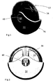
Figures 1 and 2 are perspective and front views of a first embodiment of the invention in a closed condition; -
Figures 3 and 4 are perspective and front views of a first embodiment of the invention in an open condition; -
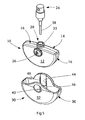
Figure 5 is an exploded view of the embodiment ofFigure 1 ; -
Figure 6 is a rear perspective view of a reservoir of the embodiment ofFigure 1 ; -
Figure 7 is a rear perspective view of a reservoir of a first alternative embodiment; -
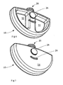
Figures 8 and 9 are perspective front and rear views of a second embodiment of the invention in a closed condition; -
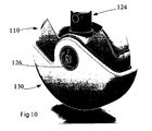
Figure 10 is a perspective front view of a second embodiment of the invention in an open condition; and -
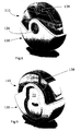
Figure 11 is an exploded view of the embodiment ofFigure 8 . - With reference to the drawings, a first embodiment of the invention is a container for 5 ml of a liquid such as a perfume or other composition for personal use.
- The container comprises a
reservoir 10 in which a liquid can be container. The reservoir has parallel spaced front andrear walls rear walls rear walls rear walls reservoir 10, the front andrear walls side wall 16, which likewise has an arcuate region and a convex region. In this embodiment, the reservoir is formed from two mouldings that are interconnected by welding, with theside wall 16 being formed substantially equally by both of the mouldings. - Each of the front and
rear walls boss 26. The bosses have a circular periphery are coaxial. Atab 28 projects from therear wall 14 - The
reservoir 10 has aneck 20 through which liquid can pass into and out of an internal space of thereservoir 10. Theneck 20 extends from a central region of the side wall at the mid-point of the convex region of theside wall 16. Theneck 20 hasengagement formation 22 that allow it to be interconnected with adispenser 24. The passage through the neck has a central axis. - In this embodiment, the
dispenser 24 is a metered-dispense finger-operated pump dispenser with a dose of 0.05mm3. It has a pump body that is carried on theengagement formations 22 of theneck 20, on which it is a snap fit where the intention is that the container is not to be refilled. A seal is formed between thedispenser 24 and the neck, so thedispenser 24 acts as a sealing closure for thereservoir 10. Adip tube 38 extends into thereservoir 10 to pick up liquid contained within it when the container is in the deployed condition. When being carried in the closed condition, thedip tube 38 may extend upwardly, and therefore not be submerged in the liquid, as shown inFigures 1 and 2 . A trigger projects from the pump body in a direction axially away from the reservoir. Since the dispenser, in this embodiment, is a component that can be obtained as a matter of routine, it will not be described here further. - As an alternative, the dispenser may be engaged on the neck with a screw thread. This allows it to be readily removed so that the reservoir can be re-filled. This allows the container to be used as a convenient way to carry a small amount of a liquid of choice. For example, a small amount of perfume can be carried for application during the day, while it would not be convenient to carry a full-size bottle of perfume.
- The container further includes a
casing 30. The casing has parallel, spaced front andrear walls 32, 34 and aperipheral wall 36. The spacing between the front andback walls 32, 34 is such that thereservoir 10 is a sliding fit between them with slight clearance, an outer surface of the front wall of thereservoir 10 being adjacent to an inner face of the front wall of thecasing 30 and an outer surface of the rear wall of thereservoir 10 being adjacent to an inner face of the rear wall of thecasing 30. An arcuate region of the periphery of the front and rear walls of the casing has a similar angular extent and a slightly larger radius than the arcuate peripheral region of thereservoir 10. The remainder of the periphery of the front and rear walls of thecasing 30 are convex, but of different shapes, as will be described in more detail below. The arcuate parts of the peripheries of the front and rear walls of thecasing 30 are interconnected by a side wall, and the space between the convex regions of the front and rear walls is an open slot. Thus, the reservoir can pass into thecasing 30 through the open slot. - The
front wall 32 of thecasing 30 has acircular aperture 40 at a region that is central of the arcuate region of its periphery. The aperture of the diameter is slightly greater than the diameter of theboss 26 of thereservoir 10. The convex region of thefront wall 32 is shaped as a bell curve, with a portion projecting to provide sufficient material to surround theaperture 40. (The particular shape is a matter of aesthetic choice, provided that there is sufficient material surrounding theaperture 40 to confer for strength.) - The rear wall 34 of the
casing 30 has a shape that is broadly similar in profile to thefront wall 32, but with a more-pronounced central projection in the convex region. Aslot 44 is formed in an inner surface of the rear wall 34, being of depth approximately half the thickness of the rear wall 34 and width substantially the same as the diameter of theaperture 40 in thefront wall 32. Theslot 44 extends from an edge of the rear wall 34 centrally of the projecting of the convex region, and ends opposite theaperture 40. At its inner end region, theslot 44 has a semi-circular end wall of substantially the same radius as that of theaperture 40. Arespective rib 46 extends parallel to and spaced from each side of theslot 44. - To assemble the container, the
reservoir 10 is introduced into thecasing 30. Theboss 26 of therear wall 14 of thereservoir 10 slides into theslot 44 in the rear wall 34 of thecasing 30. Thefront wall 32 of the casing is deflected away from the rear wall 34 to allow theboss 26 on thefront wall 12 of thereservoir 10 to pass behind it. Theboss 26 then enters theaperture 40 in thefront wall 32, and thefront wall 32 is allowed to return from its deflected condition to a natural condition. - Thus assembled, the following should be noted about the container:
- the
reservoir 10 and thecasing 30 can rotate with respect to one another about an axis that is transverse to the axis of the neck by pivoting about thebosses 26; - the periphery of the
aperture 40 and the semi-circular end wall of the slot act as surfaces against which the apertures can pivot; - separation of the
casing 30 from thereservoir 10 is resisted because oneboss 26 is retained within theaperture 40; and - the
boss 26 is visible from outside of the container through theaperture 40, so it may carry indicia, such as a manufacturer's trade mark. - To place the container in a fully-open condition, the
casing 30 is manually rotated to completely expose the trigger. The trigger will typically be pointed upwards for use so that the dip tube extends downwardly into the liquid). To reach this condition, thetab 28 must pass one orother rib 46. The position and size of thetab 28 and theribs 46 is selected such that resistance to the rotational movement occurs as thetab 28 passes the rib, and when the container is fully open, thetab 28 rests between theribs 46. Thus, thetab 28 and theribs 46 act as a detent to locate the container in the open condition. - The container is fully closed when the
casing 30 and the reservoir are rotated 180° from the open condition described above about the bosses 26 - that is, about an axis that is transverse to the axis of theneck 20. In the fully-closed condition, the trigger of thedispenser 24 is entirely enclosed within thecasing 30. However, thereservoir 10 projects from the casing, which (providing it is made of as suitable transparent material) allows its contents to be inspected. In this condition, thetab 28 rests between the ribs 44 (not at the same place as in the open condition, but displaced along their length), so that thetab 28 and theribs 46 also act as a detent to locate the container in the closed condition. - The
reservoir 10 is made of a transparent plastic material, which optionally has a coloured tint. For the user of the container, this has the advantage that the amount contained within it can be seen. It also allows the contents to be inspected, for example, by airport security officials. - The rear wall of the reservoir contains
recesses 50 that project into the reservoir such that its internal volume is substantially filled when the intended volume of liquid (5 ml) is introduced into it. In a first alternative embodiment, the recesses are omitted (as shown inFigure 7 ) to provide a container for a larger volume of liquid. For example, the dimensions of thereservoir 10 and the recesses may be such that a container for 10 ml of liquid is obtained by omission of the recesses; all other components can remain unchanged. Containers with larger volumes can be obtained by scaling the container in size. - An alternative embodiment will now be described with reference to
Figures 9 to 11 . Where components of this embodiment are similar to those of the first embodiment, they will be given a reference numeral of 100 plus that used in the description of the first embodiment. - As in the first embodiment, this embodiment includes a
reservoir 110 that carries acasing 130, the reservoir and the casting being capable of mutual rotation. Its principles of operation and construction are much the same as those of the first embodiment. - The
reservoir 110 has two interconnected components: a base 180 and a cover 182. The cover 182 is made of a transparent plastic material. The base 180 carries thedispenser 124, and itsdip tube 138 extends into the cover 182. When in the closed condition, the cover 182 projects from thecasing 130 such that the contents of thereservoir 110 can be seen through it. Thebosses 126 project from the base 180. - As will be seen from the figures, the
casing 130 of this embodiment has a different shape than that of the first embodiment. This is a predominantly aesthetic choice. - Typical dimensions of a container embodying the invention are an overall thickness of 19.5 mm, a radius of the
reservoir 110 of 25.5 mm and a radius of thecasing 130 of 27.4 mm. - Surface decoration can be applied to the container. For example, the container could be made to accord with a corporate identity, or it may simply be aesthetic. This can be printed or done by transfer. Also, decorative items such as rhinestones could be applied to achieve a desired appearance.
- In alternative embodiments, the reservoir contains a liquid product and a propellant gas under pressure, and the dispenser includes a valve and a spray head - a so-called aerosol container.
- In UK patent application
GB-A-2 431 909 WO2007/052051 the present applicants disclosed a container for products such as cosmetic preparations that can be worn about the person by interconnecting a container body with one of several alternative mounting components. The various mounting components can attach to garments or be otherwise carried about by a person. Several such mounting components are seen at 70 inFigure 11 . Arecess 72 is provided in the rear wall of thecasing 130 into which one of the mountingcomponents 70 can be received, as described in the documents mentioned above. This arrangement can be applied to all of the embodiments described above. This allows a container embodying the invention to be carried conveniently and under almost any circumstances.
Claims (15)
- A container for a liquid comprising:a. a reservoir (10) having front and rear walls (12, 14), a side wall (16) and a neck (20) extending from the side wall (16), through which neck (20) liquid can pass into and out of an internal space of the reservoir (10), each of the front and rear walls (12, 14) having an arcuate peripheral region that is shaped as a segment of a circle extending slightly more than 180°,b. a dispenser (24) carried on the neck (20) of the reservoir (10) that can dispense a quantity of liquid from the reservoir,c. a casing (30) having spaced front and rear walls (32, 34) and a peripheral wall (36), the casing (30) being carried on the reservoir (10), such that the reservoir is a sliding fit between the front and rear walls (32, 34), an outer surface of the front wall of the reservoir being adjacent to an inner face of the front wall of the casing and an outer surface of the rear wall of the reservoir being adjacent to an inner face of the rear wall of the casing; and characterised in that:d. the casing (30) and the reservoir (10) can be mutually rotated through 180° between a fully closed condition and an open condition:i. in the closed condition the casing (30) prevents access to a trigger for dispensing said quantity of liquid, and the reservoir (10) predominantly projects from the casing,ii. the reservoir includes at least one wall of a transparent or a semi-transparent material, through which the contents of the reservoir can be inspected when the container is in the closed condition, andiii. in the open condition the trigger projects from the casing such that it can be operated and the reservoir is substantially entirely received within the casing..
- A container according to claim 1 in which the reservoir (10) is made entirely of transparent material.
- A container according to claim 1 or claim 2 in which, when in the closed condition, the container presents an approximately circular peripheral shape.
- A container according to any preceding claim in which the dispenser (24) is a trigger-operated pump.
- A container according to any one of claims 1 to 3 in which the reservoir (10) is suitable for containing a liquid product and a propellant gas under pressure, and the dispenser (24) includes a valve and a spray head.
- A container according to any preceding claim having detents to retain the container in its open and/or its closed condition.
- A container according to any preceding claim in which the dispenser is permanently attached to the container.
- A container according to any one of claims 1 to 7 in which the dispenser (24) is releasably attached to the container (10).
- A container according to claim 8 in which the dispenser (24) is attached to the container (20) by a screw thread.
- A container according to any preceding claim in which the dispenser acts as a closure for the container.
- A container according to any preceding claim in which the front and rear walls (12,14) of the reservoir comprise bosses (26) and the front and rear walls (32, 34) of the casing (30) compise apertures (40) engaged with the bosses about which they can mutually pivot.
- A container according to any preceding claim in combination with a plurality of mounting components (70), any of which can be releasably connected to the container, the mounting components being suitable for connection with a garment.
- A packaged product comprising a container according to any preceding claim with a liquid product contained within its reservoir.
- A packaged product according to claim 13 in which the volume of liquid within the container is less than 50 ml.
- A packaged product according to claim 13 or claim 14 in which the liquid is a product for personal use.
Applications Claiming Priority (2)
| Application Number | Priority Date | Filing Date | Title |
|---|---|---|---|
| GB0711893A GB2450343B (en) | 2007-06-20 | 2007-06-20 | Container for a liquid |
| PCT/GB2008/002109 WO2008155553A1 (en) | 2007-06-20 | 2008-06-20 | Container for a liquid |
Publications (2)
| Publication Number | Publication Date |
|---|---|
| EP2225164A1 EP2225164A1 (en) | 2010-09-08 |
| EP2225164B1 true EP2225164B1 (en) | 2013-12-18 |
Family
ID=38332409
Family Applications (1)
| Application Number | Title | Priority Date | Filing Date |
|---|---|---|---|
| EP08762426.8A Ceased EP2225164B1 (en) | 2007-06-20 | 2008-06-20 | Container for a liquid |
Country Status (4)
| Country | Link |
|---|---|
| US (1) | US8528789B2 (en) |
| EP (1) | EP2225164B1 (en) |
| GB (1) | GB2450343B (en) |
| WO (1) | WO2008155553A1 (en) |
Families Citing this family (21)
| Publication number | Priority date | Publication date | Assignee | Title |
|---|---|---|---|---|
| USD728861S1 (en) * | 2013-03-08 | 2015-05-05 | Zen Design Solutions Limited | Cosmetic container |
| USD794472S1 (en) * | 2013-10-20 | 2017-08-15 | Beauty Union Global Limited | Refill bottle |
| US9745107B2 (en) * | 2013-12-20 | 2017-08-29 | Retro Brands, Llc | E-liquid dispenser |
| USD765908S1 (en) | 2013-12-20 | 2016-09-06 | Retro Brands, Llc | E-liquid dispenser and bottle combination |
| CN205597112U (en) * | 2013-12-20 | 2016-09-28 | 雷特罗品牌有限责任公司 | E-liquid dispenser and e-liquid bottle |
| WO2015105730A1 (en) * | 2014-01-07 | 2015-07-16 | Barbier Benjamin Arana | Hand sanitizing dispensing device |
| US20160227902A1 (en) * | 2015-02-04 | 2016-08-11 | Sillage Llc | Fragrance bottle assembly |
| USD800060S1 (en) | 2015-07-02 | 2017-10-17 | Kurt Solland | Charging case |
| US10117485B2 (en) | 2015-07-02 | 2018-11-06 | Kurt Solland | Receptacle with pivoting closure |
| US10189040B2 (en) * | 2015-07-29 | 2019-01-29 | Stephanie Vecchione | Dispensing device |
| USD780850S1 (en) * | 2015-10-22 | 2017-03-07 | Maped | Eraser |
| USD864488S1 (en) * | 2017-02-13 | 2019-10-22 | K7 Design Group Corporation | Lip balm container |
| US10321746B2 (en) | 2017-05-17 | 2019-06-18 | K7 Design Group Corporation | Lip balm and container therof |
| USD889269S1 (en) * | 2017-09-07 | 2020-07-07 | Emily Heath Studio Llc | Bottle |
| USD885849S1 (en) * | 2019-02-12 | 2020-06-02 | The Topps Company, Inc. | Dispenser for edible product |
| USD885850S1 (en) * | 2019-02-12 | 2020-06-02 | The Topps Company, Inc. | Dispenser for an edible product with associated pusher |
| USD885851S1 (en) * | 2019-02-12 | 2020-06-02 | The Topps Company, Inc. | Dispenser for edible product |
| USD885848S1 (en) * | 2019-02-12 | 2020-06-02 | The Topps Company, Inc. | Dispenser for an edible product with associated pusher |
| US12369639B2 (en) | 2019-06-21 | 2025-07-29 | Imperial Tobacco Limited | Aerosol delivery device |
| EP3753432A1 (en) * | 2019-06-21 | 2020-12-23 | Nerudia Limited | Aerosol delivery device |
| USD1111247S1 (en) * | 2024-10-25 | 2026-02-03 | Hcl Technologies Limited | Lipstick packaging |
Family Cites Families (23)
| Publication number | Priority date | Publication date | Assignee | Title |
|---|---|---|---|---|
| US829327A (en) * | 1906-04-23 | 1906-08-21 | William N Crisp | Rubber-eraser protector. |
| US2276047A (en) * | 1940-05-01 | 1942-03-10 | Kurth Alfred | Lip coloring device |
| US4051983B1 (en) * | 1975-11-19 | 1993-12-14 | Calmar Inc. | Pump sprayer having pump priming means |
| JPS55380Y2 (en) * | 1976-09-18 | 1980-01-08 | ||
| USD314511S (en) * | 1988-04-01 | 1991-02-12 | R. P. Denis S.p.A. | Combined perfume bottle and closure |
| DE9107249U1 (en) * | 1991-06-12 | 1992-10-15 | Ortner, Georg, 5000 Köln | Perfume dispenser |
| IT1256619B (en) * | 1992-12-04 | 1995-12-12 | CONTAINER OF DEVICES FOR COSMETICS AND PERSONAL HYGIENE, SUCH AS MAKE-UP AND SHAVING BRUSHES, LIPSTICKS, APPLICATORS IN GENERAL, PERFUME DISPENSERS, TOOTH BRUSHES AND SO ON. | |
| NL9301506A (en) * | 1993-09-01 | 1995-04-03 | Cornelis Elizabeth Rijlaarsdam | Container assembly with at least two containers |
| US5482187A (en) * | 1993-09-13 | 1996-01-09 | Hygienix, Inc. | Dispenser for viscous substances |
| US5833093A (en) * | 1996-03-04 | 1998-11-10 | Honaker; Denise | Protective cover for small spray dispensers and medicated inhalers |
| USD428340S (en) * | 1997-12-05 | 2000-07-18 | The Procter & Gamble Company | Container |
| US6016916A (en) * | 1998-05-13 | 2000-01-25 | Ortner; Georg | Packaging unit for rod-shaped perfume bottles |
| IT246769Y1 (en) * | 1999-06-04 | 2002-04-10 | Henkel Spa | BOTTLE IN PARTICULAR FOR PERFUME WITH SLIDING ELEMENT COVERING OF THE PRODUCT DISPENSING PART |
| JP2002034643A (en) * | 2000-07-28 | 2002-02-05 | Yoshida Industry Co Ltd | Liquid container of rotary opening/closing type |
| JP2003207151A (en) * | 2002-01-15 | 2003-07-25 | T Hasegawa Co Ltd | Flat bottom circular type air conditioner chemical vaporizer |
| USD471086S1 (en) * | 2002-03-25 | 2003-03-04 | Chanel, Inc. | Fragrance dispenser |
| ATE478814T1 (en) * | 2002-06-28 | 2010-09-15 | Procter & Gamble | PRINT RELEASE PACKAGE |
| FR2846639B1 (en) * | 2002-11-06 | 2004-12-10 | Innovation Packaging | PACKAGING AND DISPENSING DEVICE FOR A LIQUID OR SEMI-LIQUID PRODUCT |
| GB0226022D0 (en) * | 2002-11-07 | 2002-12-18 | Corporate Intellectual Propert | Device |
| FR2866866B1 (en) * | 2004-02-27 | 2008-02-22 | Crown Packaging Technology Inc | DEVICE FOR DISPENSING A FLUID AND BOTTLE |
| USD568692S1 (en) * | 2007-01-09 | 2008-05-13 | Lam Samy Hak-Tang | Big spool bubble gum tape dispenser |
| US7886395B2 (en) * | 2007-09-06 | 2011-02-15 | Acme United Corporation | Pencil sharpener with eraser |
| TWD137525S1 (en) * | 2009-05-20 | 2010-10-21 | 新康多香水公司 | Flacon voyage en hermes |
-
2007
- 2007-06-20 GB GB0711893A patent/GB2450343B/en not_active Expired - Fee Related
-
2008
- 2008-06-20 US US12/665,737 patent/US8528789B2/en not_active Expired - Fee Related
- 2008-06-20 EP EP08762426.8A patent/EP2225164B1/en not_active Ceased
- 2008-06-20 WO PCT/GB2008/002109 patent/WO2008155553A1/en not_active Ceased
Also Published As
| Publication number | Publication date |
|---|---|
| US20100282779A1 (en) | 2010-11-11 |
| EP2225164A1 (en) | 2010-09-08 |
| GB2450343A (en) | 2008-12-24 |
| US8528789B2 (en) | 2013-09-10 |
| GB0711893D0 (en) | 2007-07-25 |
| GB2450343B (en) | 2010-02-10 |
| WO2008155553A1 (en) | 2008-12-24 |
Similar Documents
| Publication | Publication Date | Title |
|---|---|---|
| EP2225164B1 (en) | Container for a liquid | |
| US10398211B2 (en) | Bottle cap with cosmetic kit | |
| US8413849B2 (en) | Secure dispensing system for multiple consumables | |
| KR100649916B1 (en) | Package for dispensing pressurized fluid | |
| US20140020706A1 (en) | Assembly for packaging and mixing cosmetic products | |
| CN113712367A (en) | Refillable cosmetic container | |
| EP3458163B1 (en) | Device for separately dispensing materials for use together on human skin | |
| US20110210039A1 (en) | Packaging System for a Cosmetic System | |
| US20170028421A1 (en) | Bottle | |
| CA2464532A1 (en) | Underarm product and package combination | |
| JP7082207B2 (en) | Duplex pump dispensing system | |
| EP3554959B1 (en) | Scented packaging | |
| US20140126948A1 (en) | Double-headed deodorant dispenser | |
| CA2966568C (en) | Bottle cap with cosmetic kit | |
| GB2569183A (en) | Rotating perfume bottle | |
| WO2018087046A1 (en) | Dispensing head with integrated reservoir for storage container | |
| US9237794B2 (en) | Lock-in cosmetic accessory sleeve apparatus having engageable and/or constriction means | |
| JP2002012247A (en) | Pouring cap for fluid substance dispensing vessel |
Legal Events
| Date | Code | Title | Description |
|---|---|---|---|
| PUAI | Public reference made under article 153(3) epc to a published international application that has entered the european phase |
Free format text: ORIGINAL CODE: 0009012 |
|
| 17P | Request for examination filed |
Effective date: 20100120 |
|
| AK | Designated contracting states |
Kind code of ref document: A1 Designated state(s): AT BE BG CH CY CZ DE DK EE ES FI FR GB GR HR HU IE IS IT LI LT LU LV MC MT NL NO PL PT RO SE SI SK TR |
|
| AX | Request for extension of the european patent |
Extension state: AL BA MK RS |
|
| DAX | Request for extension of the european patent (deleted) | ||
| 17Q | First examination report despatched |
Effective date: 20110504 |
|
| REG | Reference to a national code |
Ref country code: DE Ref legal event code: R079 Ref document number: 602008029406 Country of ref document: DE Free format text: PREVIOUS MAIN CLASS: B65D0043160000 Ipc: A45C0011240000 |
|
| GRAP | Despatch of communication of intention to grant a patent |
Free format text: ORIGINAL CODE: EPIDOSNIGR1 |
|
| RIC1 | Information provided on ipc code assigned before grant |
Ipc: B65D 83/22 20060101ALI20130503BHEP Ipc: A45C 11/24 20060101AFI20130503BHEP Ipc: B65D 43/16 20060101ALI20130503BHEP Ipc: A45D 34/02 20060101ALI20130503BHEP Ipc: B05B 11/00 20060101ALI20130503BHEP |
|
| INTG | Intention to grant announced |
Effective date: 20130522 |
|
| GRAS | Grant fee paid |
Free format text: ORIGINAL CODE: EPIDOSNIGR3 |
|
| GRAP | Despatch of communication of intention to grant a patent |
Free format text: ORIGINAL CODE: EPIDOSNIGR1 |
|
| GRAA | (expected) grant |
Free format text: ORIGINAL CODE: 0009210 |
|
| INTG | Intention to grant announced |
Effective date: 20131025 |
|
| AK | Designated contracting states |
Kind code of ref document: B1 Designated state(s): AT BE BG CH CY CZ DE DK EE ES FI FR GB GR HR HU IE IS IT LI LT LU LV MC MT NL NO PL PT RO SE SI SK TR |
|
| REG | Reference to a national code |
Ref country code: GB Ref legal event code: FG4D |
|
| REG | Reference to a national code |
Ref country code: CH Ref legal event code: EP |
|
| REG | Reference to a national code |
Ref country code: AT Ref legal event code: REF Ref document number: 645174 Country of ref document: AT Kind code of ref document: T Effective date: 20140115 |
|
| REG | Reference to a national code |
Ref country code: IE Ref legal event code: FG4D |
|
| REG | Reference to a national code |
Ref country code: DE Ref legal event code: R096 Ref document number: 602008029406 Country of ref document: DE Effective date: 20140213 |
|
| REG | Reference to a national code |
Ref country code: NL Ref legal event code: VDEP Effective date: 20131218 |
|
| PG25 | Lapsed in a contracting state [announced via postgrant information from national office to epo] |
Ref country code: NO Free format text: LAPSE BECAUSE OF FAILURE TO SUBMIT A TRANSLATION OF THE DESCRIPTION OR TO PAY THE FEE WITHIN THE PRESCRIBED TIME-LIMIT Effective date: 20140318 Ref country code: FI Free format text: LAPSE BECAUSE OF FAILURE TO SUBMIT A TRANSLATION OF THE DESCRIPTION OR TO PAY THE FEE WITHIN THE PRESCRIBED TIME-LIMIT Effective date: 20131218 Ref country code: SE Free format text: LAPSE BECAUSE OF FAILURE TO SUBMIT A TRANSLATION OF THE DESCRIPTION OR TO PAY THE FEE WITHIN THE PRESCRIBED TIME-LIMIT Effective date: 20131218 Ref country code: LT Free format text: LAPSE BECAUSE OF FAILURE TO SUBMIT A TRANSLATION OF THE DESCRIPTION OR TO PAY THE FEE WITHIN THE PRESCRIBED TIME-LIMIT Effective date: 20131218 Ref country code: HR Free format text: LAPSE BECAUSE OF FAILURE TO SUBMIT A TRANSLATION OF THE DESCRIPTION OR TO PAY THE FEE WITHIN THE PRESCRIBED TIME-LIMIT Effective date: 20131218 |
|
| REG | Reference to a national code |
Ref country code: AT Ref legal event code: MK05 Ref document number: 645174 Country of ref document: AT Kind code of ref document: T Effective date: 20131218 |
|
| REG | Reference to a national code |
Ref country code: LT Ref legal event code: MG4D |
|
| PG25 | Lapsed in a contracting state [announced via postgrant information from national office to epo] |
Ref country code: LV Free format text: LAPSE BECAUSE OF FAILURE TO SUBMIT A TRANSLATION OF THE DESCRIPTION OR TO PAY THE FEE WITHIN THE PRESCRIBED TIME-LIMIT Effective date: 20131218 |
|
| PG25 | Lapsed in a contracting state [announced via postgrant information from national office to epo] |
Ref country code: BE Free format text: LAPSE BECAUSE OF FAILURE TO SUBMIT A TRANSLATION OF THE DESCRIPTION OR TO PAY THE FEE WITHIN THE PRESCRIBED TIME-LIMIT Effective date: 20131218 Ref country code: IS Free format text: LAPSE BECAUSE OF FAILURE TO SUBMIT A TRANSLATION OF THE DESCRIPTION OR TO PAY THE FEE WITHIN THE PRESCRIBED TIME-LIMIT Effective date: 20140418 Ref country code: EE Free format text: LAPSE BECAUSE OF FAILURE TO SUBMIT A TRANSLATION OF THE DESCRIPTION OR TO PAY THE FEE WITHIN THE PRESCRIBED TIME-LIMIT Effective date: 20131218 |
|
| PG25 | Lapsed in a contracting state [announced via postgrant information from national office to epo] |
Ref country code: CZ Free format text: LAPSE BECAUSE OF FAILURE TO SUBMIT A TRANSLATION OF THE DESCRIPTION OR TO PAY THE FEE WITHIN THE PRESCRIBED TIME-LIMIT Effective date: 20131218 Ref country code: PT Free format text: LAPSE BECAUSE OF FAILURE TO SUBMIT A TRANSLATION OF THE DESCRIPTION OR TO PAY THE FEE WITHIN THE PRESCRIBED TIME-LIMIT Effective date: 20140418 Ref country code: ES Free format text: LAPSE BECAUSE OF FAILURE TO SUBMIT A TRANSLATION OF THE DESCRIPTION OR TO PAY THE FEE WITHIN THE PRESCRIBED TIME-LIMIT Effective date: 20131218 Ref country code: RO Free format text: LAPSE BECAUSE OF FAILURE TO SUBMIT A TRANSLATION OF THE DESCRIPTION OR TO PAY THE FEE WITHIN THE PRESCRIBED TIME-LIMIT Effective date: 20131218 Ref country code: AT Free format text: LAPSE BECAUSE OF FAILURE TO SUBMIT A TRANSLATION OF THE DESCRIPTION OR TO PAY THE FEE WITHIN THE PRESCRIBED TIME-LIMIT Effective date: 20131218 Ref country code: SK Free format text: LAPSE BECAUSE OF FAILURE TO SUBMIT A TRANSLATION OF THE DESCRIPTION OR TO PAY THE FEE WITHIN THE PRESCRIBED TIME-LIMIT Effective date: 20131218 Ref country code: PL Free format text: LAPSE BECAUSE OF FAILURE TO SUBMIT A TRANSLATION OF THE DESCRIPTION OR TO PAY THE FEE WITHIN THE PRESCRIBED TIME-LIMIT Effective date: 20131218 Ref country code: CY Free format text: LAPSE BECAUSE OF FAILURE TO SUBMIT A TRANSLATION OF THE DESCRIPTION OR TO PAY THE FEE WITHIN THE PRESCRIBED TIME-LIMIT Effective date: 20131218 Ref country code: NL Free format text: LAPSE BECAUSE OF FAILURE TO SUBMIT A TRANSLATION OF THE DESCRIPTION OR TO PAY THE FEE WITHIN THE PRESCRIBED TIME-LIMIT Effective date: 20131218 |
|
| REG | Reference to a national code |
Ref country code: DE Ref legal event code: R097 Ref document number: 602008029406 Country of ref document: DE |
|
| PLBE | No opposition filed within time limit |
Free format text: ORIGINAL CODE: 0009261 |
|
| STAA | Information on the status of an ep patent application or granted ep patent |
Free format text: STATUS: NO OPPOSITION FILED WITHIN TIME LIMIT |
|
| PG25 | Lapsed in a contracting state [announced via postgrant information from national office to epo] |
Ref country code: DK Free format text: LAPSE BECAUSE OF FAILURE TO SUBMIT A TRANSLATION OF THE DESCRIPTION OR TO PAY THE FEE WITHIN THE PRESCRIBED TIME-LIMIT Effective date: 20131218 |
|
| 26N | No opposition filed |
Effective date: 20140919 |
|
| REG | Reference to a national code |
Ref country code: DE Ref legal event code: R097 Ref document number: 602008029406 Country of ref document: DE Effective date: 20140919 |
|
| PG25 | Lapsed in a contracting state [announced via postgrant information from national office to epo] |
Ref country code: LU Free format text: LAPSE BECAUSE OF FAILURE TO SUBMIT A TRANSLATION OF THE DESCRIPTION OR TO PAY THE FEE WITHIN THE PRESCRIBED TIME-LIMIT Effective date: 20140620 Ref country code: MC Free format text: LAPSE BECAUSE OF FAILURE TO SUBMIT A TRANSLATION OF THE DESCRIPTION OR TO PAY THE FEE WITHIN THE PRESCRIBED TIME-LIMIT Effective date: 20131218 |
|
| REG | Reference to a national code |
Ref country code: CH Ref legal event code: PL |
|
| PG25 | Lapsed in a contracting state [announced via postgrant information from national office to epo] |
Ref country code: CH Free format text: LAPSE BECAUSE OF NON-PAYMENT OF DUE FEES Effective date: 20140630 Ref country code: LI Free format text: LAPSE BECAUSE OF NON-PAYMENT OF DUE FEES Effective date: 20140630 |
|
| PG25 | Lapsed in a contracting state [announced via postgrant information from national office to epo] |
Ref country code: SI Free format text: LAPSE BECAUSE OF FAILURE TO SUBMIT A TRANSLATION OF THE DESCRIPTION OR TO PAY THE FEE WITHIN THE PRESCRIBED TIME-LIMIT Effective date: 20131218 |
|
| PG25 | Lapsed in a contracting state [announced via postgrant information from national office to epo] |
Ref country code: MT Free format text: LAPSE BECAUSE OF FAILURE TO SUBMIT A TRANSLATION OF THE DESCRIPTION OR TO PAY THE FEE WITHIN THE PRESCRIBED TIME-LIMIT Effective date: 20131218 |
|
| PG25 | Lapsed in a contracting state [announced via postgrant information from national office to epo] |
Ref country code: BG Free format text: LAPSE BECAUSE OF FAILURE TO SUBMIT A TRANSLATION OF THE DESCRIPTION OR TO PAY THE FEE WITHIN THE PRESCRIBED TIME-LIMIT Effective date: 20131218 |
|
| REG | Reference to a national code |
Ref country code: FR Ref legal event code: PLFP Year of fee payment: 9 |
|
| PG25 | Lapsed in a contracting state [announced via postgrant information from national office to epo] |
Ref country code: GR Free format text: LAPSE BECAUSE OF FAILURE TO SUBMIT A TRANSLATION OF THE DESCRIPTION OR TO PAY THE FEE WITHIN THE PRESCRIBED TIME-LIMIT Effective date: 20140319 Ref country code: IT Free format text: LAPSE BECAUSE OF FAILURE TO SUBMIT A TRANSLATION OF THE DESCRIPTION OR TO PAY THE FEE WITHIN THE PRESCRIBED TIME-LIMIT Effective date: 20131218 |
|
| PG25 | Lapsed in a contracting state [announced via postgrant information from national office to epo] |
Ref country code: HU Free format text: LAPSE BECAUSE OF FAILURE TO SUBMIT A TRANSLATION OF THE DESCRIPTION OR TO PAY THE FEE WITHIN THE PRESCRIBED TIME-LIMIT; INVALID AB INITIO Effective date: 20080620 Ref country code: TR Free format text: LAPSE BECAUSE OF FAILURE TO SUBMIT A TRANSLATION OF THE DESCRIPTION OR TO PAY THE FEE WITHIN THE PRESCRIBED TIME-LIMIT Effective date: 20131218 |
|
| REG | Reference to a national code |
Ref country code: FR Ref legal event code: PLFP Year of fee payment: 10 |
|
| REG | Reference to a national code |
Ref country code: FR Ref legal event code: PLFP Year of fee payment: 11 |
|
| PGFP | Annual fee paid to national office [announced via postgrant information from national office to epo] |
Ref country code: IE Payment date: 20210825 Year of fee payment: 14 Ref country code: FR Payment date: 20210823 Year of fee payment: 14 |
|
| PGFP | Annual fee paid to national office [announced via postgrant information from national office to epo] |
Ref country code: GB Payment date: 20210823 Year of fee payment: 14 Ref country code: DE Payment date: 20210831 Year of fee payment: 14 |
|
| REG | Reference to a national code |
Ref country code: DE Ref legal event code: R119 Ref document number: 602008029406 Country of ref document: DE |
|
| GBPC | Gb: european patent ceased through non-payment of renewal fee |
Effective date: 20220620 |
|
| PG25 | Lapsed in a contracting state [announced via postgrant information from national office to epo] |
Ref country code: IE Free format text: LAPSE BECAUSE OF NON-PAYMENT OF DUE FEES Effective date: 20220620 Ref country code: FR Free format text: LAPSE BECAUSE OF NON-PAYMENT OF DUE FEES Effective date: 20220630 |
|
| PG25 | Lapsed in a contracting state [announced via postgrant information from national office to epo] |
Ref country code: GB Free format text: LAPSE BECAUSE OF NON-PAYMENT OF DUE FEES Effective date: 20220620 Ref country code: DE Free format text: LAPSE BECAUSE OF NON-PAYMENT OF DUE FEES Effective date: 20230103 |