EP2224732B1 - Video device - Google Patents
Video device Download PDFInfo
- Publication number
- EP2224732B1 EP2224732B1 EP10154773A EP10154773A EP2224732B1 EP 2224732 B1 EP2224732 B1 EP 2224732B1 EP 10154773 A EP10154773 A EP 10154773A EP 10154773 A EP10154773 A EP 10154773A EP 2224732 B1 EP2224732 B1 EP 2224732B1
- Authority
- EP
- European Patent Office
- Prior art keywords
- controller
- broadcast signal
- visually impaired
- display component
- light source
- Prior art date
- Legal status (The legal status is an assumption and is not a legal conclusion. Google has not performed a legal analysis and makes no representation as to the accuracy of the status listed.)
- Not-in-force
Links
Images


Classifications
-
- H—ELECTRICITY
- H04—ELECTRIC COMMUNICATION TECHNIQUE
- H04N—PICTORIAL COMMUNICATION, e.g. TELEVISION
- H04N5/00—Details of television systems
- H04N5/44—Receiver circuitry for the reception of television signals according to analogue transmission standards
- H04N5/60—Receiver circuitry for the reception of television signals according to analogue transmission standards for the sound signals
-
- H—ELECTRICITY
- H04—ELECTRIC COMMUNICATION TECHNIQUE
- H04N—PICTORIAL COMMUNICATION, e.g. TELEVISION
- H04N21/00—Selective content distribution, e.g. interactive television or video on demand [VOD]
- H04N21/40—Client devices specifically adapted for the reception of or interaction with content, e.g. set-top-box [STB]; Operations thereof
- H04N21/43—Processing of content or additional data, e.g. demultiplexing additional data from a digital video stream; Elementary client operations, e.g. monitoring of home network or synchronising decoder's clock; Client middleware
- H04N21/435—Processing of additional data, e.g. decrypting of additional data, reconstructing software from modules extracted from the transport stream
-
- H—ELECTRICITY
- H04—ELECTRIC COMMUNICATION TECHNIQUE
- H04N—PICTORIAL COMMUNICATION, e.g. TELEVISION
- H04N21/00—Selective content distribution, e.g. interactive television or video on demand [VOD]
- H04N21/40—Client devices specifically adapted for the reception of or interaction with content, e.g. set-top-box [STB]; Operations thereof
- H04N21/43—Processing of content or additional data, e.g. demultiplexing additional data from a digital video stream; Elementary client operations, e.g. monitoring of home network or synchronising decoder's clock; Client middleware
- H04N21/443—OS processes, e.g. booting an STB, implementing a Java virtual machine in an STB or power management in an STB
- H04N21/4436—Power management, e.g. shutting down unused components of the receiver
-
- H—ELECTRICITY
- H04—ELECTRIC COMMUNICATION TECHNIQUE
- H04N—PICTORIAL COMMUNICATION, e.g. TELEVISION
- H04N21/00—Selective content distribution, e.g. interactive television or video on demand [VOD]
- H04N21/40—Client devices specifically adapted for the reception of or interaction with content, e.g. set-top-box [STB]; Operations thereof
- H04N21/47—End-user applications
- H04N21/485—End-user interface for client configuration
-
- H—ELECTRICITY
- H04—ELECTRIC COMMUNICATION TECHNIQUE
- H04N—PICTORIAL COMMUNICATION, e.g. TELEVISION
- H04N21/00—Selective content distribution, e.g. interactive television or video on demand [VOD]
- H04N21/40—Client devices specifically adapted for the reception of or interaction with content, e.g. set-top-box [STB]; Operations thereof
- H04N21/47—End-user applications
- H04N21/488—Data services, e.g. news ticker
-
- H—ELECTRICITY
- H04—ELECTRIC COMMUNICATION TECHNIQUE
- H04N—PICTORIAL COMMUNICATION, e.g. TELEVISION
- H04N21/00—Selective content distribution, e.g. interactive television or video on demand [VOD]
- H04N21/80—Generation or processing of content or additional data by content creator independently of the distribution process; Content per se
- H04N21/81—Monomedia components thereof
- H04N21/8106—Monomedia components thereof involving special audio data, e.g. different tracks for different languages
-
- H—ELECTRICITY
- H04—ELECTRIC COMMUNICATION TECHNIQUE
- H04N—PICTORIAL COMMUNICATION, e.g. TELEVISION
- H04N21/00—Selective content distribution, e.g. interactive television or video on demand [VOD]
- H04N21/80—Generation or processing of content or additional data by content creator independently of the distribution process; Content per se
- H04N21/83—Generation or processing of protective or descriptive data associated with content; Content structuring
- H04N21/84—Generation or processing of descriptive data, e.g. content descriptors
Definitions
- the present invention generally relates to a video device. More specifically, the present invention relates to a video device that receives digital broadcasts. Background Information
- the audio stream of the transmitted TS is made up of a plurality of sets (or tracks) of audio data made for different languages.
- this audio stream includes audio data for the visually impaired.
- Audio for the visually impaired is usually necessary when a visually impaired person views a television program, but video is often unnecessary.
- the video is displayed during viewing of the television program regardless of who the viewer is. This meant that, in the case of a liquid crystal television, for example, power consumption by the backlight is wasted.
- conventional technologies related to video and audio muting are well known (see Japanese Laid-Open Patent Application Publications Nos. 2007-089146 , 2006-054613 , 2006-033677 , and 2005-020725 , for example), but do not disclose a solution to the above problem.
- One object of the present invention is to provide a video device with which power consumption can be reduced when a visually impaired person views television programs.
- this video device it is possible to provide a video device with which power consumption can be reduced when a visually impaired person views television programs.
- FIG. 1 is a block diagram of a television receiver in accordance with one embodiment
- FIG. 2 is a diagram illustrating a service description table stored in a temporary memory of the television receiver illustrated in FIG. 1 ;
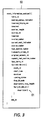
- FIG. 3 is a diagram illustrating an event information table stored in the temporary memory
- FIG. 4 is a flowchart illustrating an operation of the television receiver illustrated in FIG. 1 ;
- FIG. 5 is a detail diagram illustrating descriptors stored in the temporary memory
- FIG. 6 is a data table stored in the temporary memory
- FIG. 7 is a diagram illustrating an OSD (on screen display) displayed on a display component of the television receiver illustrated in FIG. 1 .
- FIG. 1 is a block diagram of a television receiver (e.g., video device) (hereinafter referred to as TV) 100.
- the TV 100 includes a controller 11, a control interface 12, a memory 13, a temporary memory 14, a broadcast signal processor 15, an OSD (on screen display) processor 16, a video stream processor 17, an audio stream processor 18, a data stream processor 19, a video signal output component 20, an audio signal output component 21, a display component 22, a light source 23, and a speaker 24.
- the controller 11 includes CPU (central processing unit), for example, and controls the various components of the TV 100.
- the control interface 12 includes a light receiver (not shown) that receives operation commands sent from a remote control device, or a button component (not shown) provided to a front panel of the TV 100.
- the TV 100 executes specific operations according to the operation (e.g., operation input) of the control interface 12.
- the memory 13 includes a flash ROM (read only memory), a hard disk, or the like.
- Various kinds of software, such as application software, are stored in the memory 13.
- the temporary memory 14 includes a RAM (random access memory), for example, and stores data needed for computation processing and control processing by the controller 11.
- the broadcast signal processor 15 includes a tuner, a demultiplexer, or the like, and converts digital broadcast signals received by an antenna N into a transport stream (TS), and then separates this TS into individual streams having a video stream, an audio stream, and a data stream. After this separation, the video stream is outputted to the video stream processor 17, the audio stream is outputted to the audio stream processor 18, and the data stream is outputted to the data stream processor 19.
- TS transport stream
- the OSD processor 16 produces OSD data for displaying images, characters, or various other kinds of data on the display component 22, and outputs this data to the video signal output component 20.
- the video stream processor 17 subjects the inputted video stream to image processing or other specific processing, and converts the video stream that has undergone this processing into a video signal. Furthermore, the video stream processor 17 outputs the video signal to the video signal output component 20.
- the audio stream processor 18 subjects the inputted audio stream to audio processing or other specific processing, and converts the audio stream that has undergone this processing into an audio signal. Furthermore, the audio stream processor 18 outputs the audio signal to the audio signal output component 21.
- the data stream processor 19 subjects the inputted data stream to data processing or other specific processing, thereby extracting various kinds of data included in the data stream. Furthermore, the data stream processor 19 outputs the extracted data to the temporary memory 14.
- the data outputted from the data stream processor 19 to the temporary memory 14 here includes a service description table (SDT) 30 illustrated in FIG. 2 , an event information table (EIT) 50 illustrated in FIG. 3 , and a data table 70 illustrated in FIG. 6 .
- SDT service description table
- EIT event information table
- data table 70 illustrated in FIG. 6 .
- the SDT 30 illustrated in FIG. 2 includes a plurality of descriptors that represent information such as the "channel name” or "broadcast company name” related to the tuned television program.
- the EIT 50 illustrated in FIG. 3 includes a plurality of descriptors that represent information such as the "program name,” "broadcast date and time,” and "program content” related to the tuned television program.
- descriptors 31 in the SDT 30 and/or descriptors 51 in the EIT 50 include two descriptors 60 illustrated in FIG. 5 .
- the descriptors 60 include a descriptor 61 shown as "stream_content” and a descriptor 62 shown as “component_type.”
- a specific numerical value 63 is described in the place shown by "*****” in the descriptor 61
- a specific numerical value 64 is described in the place shown by "*****" in the descriptor 62.
- the numerical value 63 added to the descriptor 61 and the numerical value 64 added to the descriptor 62 are used to confirm details about the video stream, audio stream, and data stream.
- the descriptor 61 and the descriptor 62 are paired, and a plurality of pairs is readied for each stream.
- a category 71 corresponding to the descriptor 61 and a category 72 corresponding to the descriptor 62 are referred to in the data table 70 by the controller 11.
- the category 71 having the same numerical value as the numerical value 63 added to the descriptor 61, and the category 72 having the same numerical value as the numerical value 64 added to the descriptor 62 are detected by the controller 11. Then, detailed information about each stream is confirmed by referring to a category 73 corresponding to the two detected categories (category 71 and category 72).
- the video signal output component 20 combines the inputted video signal with OSD data outputted from the OSD processor 16, and outputs this to the display component 22.
- the light source 23 adjusts the brightness of the video displayed on the display component 22.
- the display component 22 includes an LCD (liquid crystal display), for example, and the light source 23 includes a CCFL (cold cathode fluorescent lamp).
- the light source 23 is switched off (e.g., turned off)
- the video displayed on the display component 22 enters a non-display state, in which the video is not displayed on the display component 22.
- the audio signal output component 21 amplifies the inputted audio signal and outputs it to the speaker 24.
- step S1 the SDT 30 ( FIG. 2 ) and/or the EIT 50 ( FIG. 3 ) are acquired from the data stream in the data stream processor 19 under the control of the controller 11 ( FIG. 1 ).
- the acquired SDT 30 and/or EIT 50 are stored in the temporary memory 14 ( FIG. 1 ).
- step S2 the controller 11 stars verifying the SDT 30 and/or EIT 50 stored in the temporary memory 14. More specifically, the descriptors 31 in the SDT 30 and the descriptors 51 in the EIT 50 are verified. Then, the numerical value 63 added to the descriptor 61 ( FIG. 5 ) and the numerical value 64 added to the descriptor 62 ( FIG. 5 ), given by the descriptors 31 and/or the descriptors 51, are confirmed.
- step S3 the controller 11 verifies whether or not audio data for the visually impaired is included in the audio stream for the tuned television program based on the verification result in step S2. If the result of this verification is that there is audio data for the visually impaired ("Yes” in step S3), then the flow proceeds to step S4. On the other hand, if there is no audio data for the visually impaired ("No" in step S3), then the flow proceeds to step S7b.
- the controller 11 refers to the category 71 corresponding to the descriptor 61 and the category 72 corresponding to the descriptor 62, and then the category 71 having the same numerical value as the numerical value 63 confirmed in step S2 and, similarly, the category 72 having the same numerical value as the numerical value 64 confirmed in step S2 are detected from the data table 70 stored in the temporary memory 14 as shown in FIG. 6 . Then, the controller 11 refers to the category 73 corresponding to the two detected categories (the category 71 and the category 72). As a result, the controller 11 confirms whether or not there is a descriptor related to audio data for the visually impaired in the category 73. If there is such a descriptor, then the controller 11 recognizes that the audio stream includes audio data for the visually impaired.
- the category 71 having the same numerical value as the numerical value 63 and the category 72 having the same numerical value as the numerical value 64 are the places highlighted in gray in FIG. 6 .
- the category 73 corresponding to the category 71 and the category 72 describes "MPEG-1 Layer 2 audio description for the visually impaired".
- the controller 11 recognizes that the audio stream of the tuned television program includes audio data for the visually impaired.
- step S4 the controller 11 verifies whether or not the function of "visually impaired viewer priority setting" is activated.
- the "visually impaired viewer priority setting” indicates that a visually impaired person is viewing a television program. If the result of this verification is that the setting is activated ("Yes” in step S4), then the flow proceeds to step S5. On the other hand, if the setting is inactivated ("No" in step S4), then the flow proceeds to step S7b.
- the "visually impaired viewer priority setting” is preset by performing a specific operation with the control interface 12, which is done by someone other than the visually impaired person, such as a family member or the person who installs the TV 100. Furthermore, information related to the "visually impaired viewer priority setting" is stored in the memory 13 (or the temporary memory 14), for example. If the function of "visually impaired viewer priority setting" is activated, then this function is executed when a channel is changed, or when the TV 100 is started up (when the power is switched on).
- the control interface 12 and the memory 13 (or the temporary memory 14) here are examples of the preset component (or preset means).
- step S5 the controller 11 executes final confirmation of whether or not the "visually impaired viewer priority setting" is reflected during viewing of a television program.
- This final confirmation is carried out by displaying the OSD 80 shown in FIG. 7 on the display component 22.
- the data of the OSD 80 is produced by the OSD processor 16 under the control of the controller 11.
- the OSD 80 here is an example of the notice information.
- step S6 the controller 11 verifies whether or not there has been an input operation (e.g., operation input) with the control interface 12 within a specific, preset length of time after the OSD 80 is displayed on the display component 22.
- the specific, preset length of time is set to 3 minutes, 5 minutes, and so forth, for example. If the result of this verification is that there is no input operation ("No" in step S6), then the flow proceeds to step S7a. On the other hand, if there is an input operation ("Yes" in step S6), then the flow proceeds to step S7b.
- the input operation verified in step S6 means an operation in which "No" is selected on the OSD 80. If there is no input operation within the specific length of time, then the OSD 80 displayed on the display component 22 automatically goes away.
- step S7a viewing of the television program begins with the "visually impaired viewer priority setting" being reflected
- step S7b viewing of the television program begins without the "visually impaired viewer priority setting” being reflected.
- the audio signal output component 21 outputs normal audio (e.g., main audio) along with audio for the visually impaired (e.g., sub audio) to the speaker 24.
- the normal audio includes dialogue or sound of the video of the television program.
- the audio for the visually impaired includes audio commentary describing what is happening on the video of the television program for the visually impaired.
- the controller 11 switches off (or turned off) the light source 23 so that the video displayed on the display component 22 enters the non-display state.
- step S7b the television program is viewed in the normal state (or display state). In other words, the light source 23 is turned on so that the video is displayed on the display component 22 and only the normal audio is outputted from the speaker 24.
- step S8 the controller 11 verifies whether or not the control interface 12 has been operated during viewing of a television program. If the result of this verification is that there is no input operation with the control interface 12 ("No" in step S8), then the flow proceeds to step S9a. On the other hand, if there is an input operation with the control interface 12 ("Yes” in step S8), then the flow proceeds to step S9b. If the input operation is made with the control interface 12, then the controller 11 again turns on the light source 23 and displays the video on the display component 22.
- step S9a viewing of the television program that reflects the "visually impaired priority setting" is continued. Then, the operation of this flowchart is ended by turning off the power to the TV 100, for example.
- step S9b if the input operation performed in step S8 is a tuning operation of a channel ("Yes" in step S9b), then the flow returns to just before step S1. On the other hand, if the input operation performed in step S8 is not a tuning operation (such as if it is a volume adjustment) ("No" in step S9b), then the flow returns to just before step S5.
- the TV 100 mainly includes the controller 11, the broadcast signal processor 15, the display component 22, the speaker 24, and the light source 23.
- the controller 11 controls the various components of the TV 100.
- the broadcast signal processor 15 receives the digital broadcast signal and performs specific signal processing.
- the display component 22 displays video based on the output from the broadcast signal processor 15.
- the speaker 24 outputs audio based on the output from the broadcast signal processor 15.
- the light source 23 is used for the display component 22.
- the controller 11 verifies whether or not the digital broadcast signal includes audio for the visually impaired. If the audio for the visually impaired is included, then the controller 11 outputs the audio for the visually impaired and the normal audio from the speaker 24, and switches off the light source 23 so that the video displayed on the display component is in the non-display state.
- the output of audio for the visually impaired is accompanied by the light source 23 being switched off, allowing the video displayed on the display component 22 to be put in the non-display state. This saves on power consumption.
- the controller 11 refers to the category 71 corresponding to the descriptor 61 and the category 72 corresponding to the descriptor 62 in the data table 70. Furthermore, the category 71 having the same numerical value as the numerical value 63 and the category 72 having the same numerical value as the numerical value 64 are detected by the controller 11. Moreover, the controller 11 refers to the category 73 corresponding to the detection result.
- the normal audio is outputted along with the audio for the visually impaired to the speaker 24, and the light source 23 is switched off so that the video displayed on the display component 22 enters the non-display state. Consequently, when a television program is viewed by a visually impaired person, that is, when there is no need to display video, the light source 23 is automatically switched off and the video displayed on the display component 22 can be shut off. As a result, this saves on power consumption.
- the TV 100 further includes the control interface 12 and the memory 13 as a preset means.
- the preset means pre-selects that the light source 23 will be switched off and the video displayed on the display component 22 will be put in the non-display state when the digital broadcast signal includes audio for the visually impaired. If the digital broadcast signal includes audio for the visually impaired and the preset means has selected that the video will be put in the non-display state, then the light source 23 is switched off and the video displayed on the display component 22 is put in the non-displayed state. If the digital broadcast signal includes audio for the visually impaired and the preset means has not selected that the video will be put in the non-displayed state, then the light source 23 is switched on and the video is displayed on the display component22. Furthermore, if the digital broadcast signal does not include audio for the visually impaired, then the light source 23 is switched on and the video is displayed on the display component 22.
- step S3 if there is audio data for the visually impaired ("Yes” in step S3), and if the function of "visually impaired viewer priority setting," which assumes that a visually impaired person is viewing a television program, is activated (“Yes” in step S4), then the light source 23 is switched off and the video displayed on the display component 22 is shut off (step S7a). If there is audio data for the visually impaired ("Yes” in step S3), and the function of "visually impaired viewer priority setting" is inactivated (“No” in step S4), then the light source 23 is switched on and the video is displayed on the display component 22 (step S7b).
- step S3 if there is no audio data for the visually impaired ("No" in step S3), then the light source 23 is switched on and the video is displayed on the display component 22 (step S7b). Therefore, whether or not video is displayed can be selected according to the viewer, which makes the TV 100 more convenient to viewers.
- the TV 100 further includes the control interface 12 for operating the TV 100.
- the controller 11 displays the notice information notifying that the video displayed on the display component 22 will be put in the non-display state before the light source 23 is switched off and the state changes to the non-display state. If there is no specific operation of the control interface 12 within the specific length of time after the display of this notice information, then the state changes to the non-display state. On the other hand, if there is a specific operation of the control interface 12 within the specific length of time, then the state does not change to the non-display state.
- the TV 100 when a visually impaired person views together with someone with normal vision, if the specific operation is made with the control interface 12 within the specific length of time after the display of the notice information, then the display of video will be maintained, which makes the TV 100 more convenient for persons who are not visually impaired.
- the OSD 80 for final confirmation of whether or not the "visually impaired priority setting" is reflected is displayed on the display component 22 (step S5). If there is no input operation with the control interface 12 within the specific, preset length of time since this display of the OSD 80 ("No” in step S6), then the viewing of the television program that reflects the "visually impaired priority setting" is begun (step S7a). On the other hand, if there is an input operation with the control interface 12 within the specific, preset length of time since this display of the OSD 80 ("Yes” in step S6), then the viewing of the television program that does not reflect the "visually impaired viewer priority setting" is begun (step S7b).
- the TV 100 is given as an example of a video device, but the application is not limited to this.
- the video device can instead be a projector, a PC (personal computer), portable terminal, or other such video device.
- the display component 22 includes the LCD and the light source 23 includes the CCFL.
- the display component 22 and the light source 23 can be used instead as the display component 22 and the light source 23.
- an ELP electroactive panel
- PDP plasma display panel
- the display itself is made up of a light source can also be used.
- step S7b in FIG. 4 the video is displayed on the display component 22, and only the normal audio is outputted from the speaker 24. However, if there is audio for the visually impaired, then this audio for the visually impaired can also be outputted along with the normal audio to the speaker 24 in step S7b.
- detect as used herein to describe an operation or function carried out by a component, a section, a device or the like includes a component, a section, a device or the like that does not require physical detection, but rather includes determining, measuring, modeling, predicting or computing or the like to carry out the operation or function.
- configured as used herein to describe a component, section or part of a device includes hardware and/or software that is constructed and/or programmed to carry out the desired function.
Abstract
Description
- This application claims priority to Japanese Patent Application No.
2009-043755 filed on February 26,2009 - The present invention generally relates to a video device. More specifically, the present invention relates to a video device that receives digital broadcasts. Background Information
- Advances in digital technology in recent years have led to digital conversion in the field of broadcasting as well. For example, digital broadcasts have been practical in such areas as digital terrestrial television broadening, BS (broadcast satellite) digital broadcasting, CS (communications satellite) digital broadcasting, and so forth. With such digital broadcasting, video, audio, data, and other such individual streams are handled by a common signal format, and a transport stream (TS) of multiplexed signals is sent to a video device compatible with the digital broadcasting.
- In Europe there are many countries that border on multiple neighboring countries, so digital broadcast programs that are broadcast by each of these countries (hereinafter referred to as "television programs") includes one video and a plurality of audio tracks, for example. Accordingly, the audio stream of the transmitted TS is made up of a plurality of sets (or tracks) of audio data made for different languages. Also, this audio stream includes audio data for the visually impaired. As a result, when a visually impaired person views a television program, if audio data for the visually impaired is preselected, for example, the user can listen to the audio that describes the scene in addition to the normal audio. Thus, the user can understand the television program.
- Audio for the visually impaired is usually necessary when a visually impaired person views a television program, but video is often unnecessary. However, with a conventional video device, the video is displayed during viewing of the television program regardless of who the viewer is. This meant that, in the case of a liquid crystal television, for example, power consumption by the backlight is wasted. Furthermore, conventional technologies related to video and audio muting are well known (see Japanese Laid-Open Patent Application Publications Nos.
2007-089146 2006-054613 2006-033677 2005-020725 - The present invention was conceived in light of the above-mentioned problems. One object of the present invention is to provide a video device with which power consumption can be reduced when a visually impaired person views television programs.
- In accordance with one aspect of the present invention, there is provided a video device in accordance with
claim 1. - With this video device, it is possible to provide a video device with which power consumption can be reduced when a visually impaired person views television programs.
- Referring now to the attached drawings which form a part of this original disclosure:
-
FIG. 1 is a block diagram of a television receiver in accordance with one embodiment; -
FIG. 2 is a diagram illustrating a service description table stored in a temporary memory of the television receiver illustrated inFIG. 1 ; -
FIG. 3 is a diagram illustrating an event information table stored in the temporary memory; -
FIG. 4 is a flowchart illustrating an operation of the television receiver illustrated inFIG. 1 ; -
FIG. 5 is a detail diagram illustrating descriptors stored in the temporary memory; -
FIG. 6 is a data table stored in the temporary memory; and -
FIG. 7 is a diagram illustrating an OSD (on screen display) displayed on a display component of the television receiver illustrated inFIG. 1 . - A preferred embodiment will now be explained with reference to the drawings. It will be apparent to those skilled in the art from this disclosure that the following descriptions of the preferred embodiment are provided for illustration only and not for the purpose of limiting the invention as defined by the appended claims and their equivalents.
-
FIG. 1 is a block diagram of a television receiver (e.g., video device) (hereinafter referred to as TV) 100. The TV 100 includes acontroller 11, acontrol interface 12, amemory 13, atemporary memory 14, abroadcast signal processor 15, an OSD (on screen display)processor 16, avideo stream processor 17, anaudio stream processor 18, adata stream processor 19, a videosignal output component 20, an audiosignal output component 21, adisplay component 22, alight source 23, and aspeaker 24. Thecontroller 11 includes CPU (central processing unit), for example, and controls the various components of theTV 100. - The
control interface 12 includes a light receiver (not shown) that receives operation commands sent from a remote control device, or a button component (not shown) provided to a front panel of theTV 100. TheTV 100 executes specific operations according to the operation (e.g., operation input) of thecontrol interface 12. - The
memory 13 includes a flash ROM (read only memory), a hard disk, or the like. Various kinds of software, such as application software, are stored in thememory 13. Thetemporary memory 14 includes a RAM (random access memory), for example, and stores data needed for computation processing and control processing by thecontroller 11. - The
broadcast signal processor 15 includes a tuner, a demultiplexer, or the like, and converts digital broadcast signals received by an antenna N into a transport stream (TS), and then separates this TS into individual streams having a video stream, an audio stream, and a data stream. After this separation, the video stream is outputted to thevideo stream processor 17, the audio stream is outputted to theaudio stream processor 18, and the data stream is outputted to thedata stream processor 19. - The OSD
processor 16 produces OSD data for displaying images, characters, or various other kinds of data on thedisplay component 22, and outputs this data to the videosignal output component 20. - The
video stream processor 17 subjects the inputted video stream to image processing or other specific processing, and converts the video stream that has undergone this processing into a video signal. Furthermore, thevideo stream processor 17 outputs the video signal to the videosignal output component 20. - The
audio stream processor 18 subjects the inputted audio stream to audio processing or other specific processing, and converts the audio stream that has undergone this processing into an audio signal. Furthermore, theaudio stream processor 18 outputs the audio signal to the audiosignal output component 21. - The
data stream processor 19 subjects the inputted data stream to data processing or other specific processing, thereby extracting various kinds of data included in the data stream. Furthermore, thedata stream processor 19 outputs the extracted data to thetemporary memory 14. - The data outputted from the
data stream processor 19 to thetemporary memory 14 here includes a service description table (SDT) 30 illustrated inFIG. 2 , an event information table (EIT) 50 illustrated inFIG. 3 , and a data table 70 illustrated inFIG. 6 . - More specifically, the SDT 30 illustrated in
FIG. 2 includes a plurality of descriptors that represent information such as the "channel name" or "broadcast company name" related to the tuned television program. Furthermore, the EIT 50 illustrated inFIG. 3 includes a plurality of descriptors that represent information such as the "program name," "broadcast date and time," and "program content" related to the tuned television program. - Also,
descriptors 31 in theSDT 30 and/ordescriptors 51 in theEIT 50 include twodescriptors 60 illustrated inFIG. 5 . Thedescriptors 60 include adescriptor 61 shown as "stream_content" and adescriptor 62 shown as "component_type." A specificnumerical value 63 is described in the place shown by "*****" in thedescriptor 61, and a specificnumerical value 64 is described in the place shown by "*****" in thedescriptor 62. Thenumerical value 63 added to thedescriptor 61 and thenumerical value 64 added to thedescriptor 62 are used to confirm details about the video stream, audio stream, and data stream. Thus, thedescriptor 61 and thedescriptor 62 are paired, and a plurality of pairs is readied for each stream. - As shown in
FIG. 6 , when the details about the video stream, audio stream, and data stream are confirmed, acategory 71 corresponding to thedescriptor 61 and acategory 72 corresponding to thedescriptor 62 are referred to in the data table 70 by thecontroller 11. In particular, thecategory 71 having the same numerical value as thenumerical value 63 added to thedescriptor 61, and thecategory 72 having the same numerical value as thenumerical value 64 added to thedescriptor 62 are detected by thecontroller 11. Then, detailed information about each stream is confirmed by referring to acategory 73 corresponding to the two detected categories (category 71 and category 72). - The video
signal output component 20 combines the inputted video signal with OSD data outputted from theOSD processor 16, and outputs this to thedisplay component 22. Thelight source 23 adjusts the brightness of the video displayed on thedisplay component 22. Thedisplay component 22 includes an LCD (liquid crystal display), for example, and thelight source 23 includes a CCFL (cold cathode fluorescent lamp). When thelight source 23 is switched off (e.g., turned off), the video displayed on thedisplay component 22 enters a non-display state, in which the video is not displayed on thedisplay component 22. The audiosignal output component 21 amplifies the inputted audio signal and outputs it to thespeaker 24. - With the
TV 100, when a visually impaired person views a television program, an operation shown in the flowchart ofFIG. 4 is executed. - More specifically, in step S1, the SDT 30 (
FIG. 2 ) and/or the EIT 50 (FIG. 3 ) are acquired from the data stream in thedata stream processor 19 under the control of the controller 11 (FIG. 1 ). The acquiredSDT 30 and/orEIT 50 are stored in the temporary memory 14 (FIG. 1 ). - In step S2, the
controller 11 stars verifying theSDT 30 and/orEIT 50 stored in thetemporary memory 14. More specifically, thedescriptors 31 in theSDT 30 and thedescriptors 51 in theEIT 50 are verified. Then, thenumerical value 63 added to the descriptor 61 (FIG. 5 ) and thenumerical value 64 added to the descriptor 62 (FIG. 5 ), given by thedescriptors 31 and/or thedescriptors 51, are confirmed. - In step S3, the
controller 11 verifies whether or not audio data for the visually impaired is included in the audio stream for the tuned television program based on the verification result in step S2. If the result of this verification is that there is audio data for the visually impaired ("Yes" in step S3), then the flow proceeds to step S4. On the other hand, if there is no audio data for the visually impaired ("No" in step S3), then the flow proceeds to step S7b. - More specifically, the
controller 11 refers to thecategory 71 corresponding to thedescriptor 61 and thecategory 72 corresponding to thedescriptor 62, and then thecategory 71 having the same numerical value as thenumerical value 63 confirmed in step S2 and, similarly, thecategory 72 having the same numerical value as thenumerical value 64 confirmed in step S2 are detected from the data table 70 stored in thetemporary memory 14 as shown inFIG. 6 . Then, thecontroller 11 refers to thecategory 73 corresponding to the two detected categories (thecategory 71 and the category 72). As a result, thecontroller 11 confirms whether or not there is a descriptor related to audio data for the visually impaired in thecategory 73. If there is such a descriptor, then thecontroller 11 recognizes that the audio stream includes audio data for the visually impaired. - For example, if the
numerical value 63 added to thedescriptor 61 is "0 x 02," and thenumerical value 64 added to thedescriptor 62 is "0 × 40", then thecategory 71 having the same numerical value as thenumerical value 63 and thecategory 72 having the same numerical value as thenumerical value 64 are the places highlighted in gray inFIG. 6 . As shown inFIG. 6 , thecategory 73 corresponding to thecategory 71 and thecategory 72 describes "MPEG-1Layer 2 audio description for the visually impaired". Thus, thecontroller 11 recognizes that the audio stream of the tuned television program includes audio data for the visually impaired. - In step S4, the
controller 11 verifies whether or not the function of "visually impaired viewer priority setting" is activated. The "visually impaired viewer priority setting" indicates that a visually impaired person is viewing a television program. If the result of this verification is that the setting is activated ("Yes" in step S4), then the flow proceeds to step S5. On the other hand, if the setting is inactivated ("No" in step S4), then the flow proceeds to step S7b. - The "visually impaired viewer priority setting" is preset by performing a specific operation with the
control interface 12, which is done by someone other than the visually impaired person, such as a family member or the person who installs theTV 100. Furthermore, information related to the "visually impaired viewer priority setting" is stored in the memory 13 (or the temporary memory 14), for example. If the function of "visually impaired viewer priority setting" is activated, then this function is executed when a channel is changed, or when theTV 100 is started up (when the power is switched on). Thecontrol interface 12 and the memory 13 (or the temporary memory 14) here are examples of the preset component (or preset means). - In step S5, the
controller 11 executes final confirmation of whether or not the "visually impaired viewer priority setting" is reflected during viewing of a television program. This final confirmation is carried out by displaying theOSD 80 shown inFIG. 7 on thedisplay component 22. The data of theOSD 80 is produced by theOSD processor 16 under the control of thecontroller 11. TheOSD 80 here is an example of the notice information. - In step S6, the
controller 11 verifies whether or not there has been an input operation (e.g., operation input) with thecontrol interface 12 within a specific, preset length of time after theOSD 80 is displayed on thedisplay component 22. Here, the specific, preset length of time is set to 3 minutes, 5 minutes, and so forth, for example. If the result of this verification is that there is no input operation ("No" in step S6), then the flow proceeds to step S7a. On the other hand, if there is an input operation ("Yes" in step S6), then the flow proceeds to step S7b. The input operation verified in step S6 means an operation in which "No" is selected on theOSD 80. If there is no input operation within the specific length of time, then theOSD 80 displayed on thedisplay component 22 automatically goes away. - In step S7a, viewing of the television program begins with the "visually impaired viewer priority setting" being reflected, and in step S7b, viewing of the television program begins without the "visually impaired viewer priority setting" being reflected. More specifically, in step S7a, the audio
signal output component 21 outputs normal audio (e.g., main audio) along with audio for the visually impaired (e.g., sub audio) to thespeaker 24. The normal audio includes dialogue or sound of the video of the television program. The audio for the visually impaired includes audio commentary describing what is happening on the video of the television program for the visually impaired. Also, thecontroller 11 switches off (or turned off) thelight source 23 so that the video displayed on thedisplay component 22 enters the non-display state. Meanwhile, in step S7b, the television program is viewed in the normal state (or display state). In other words, thelight source 23 is turned on so that the video is displayed on thedisplay component 22 and only the normal audio is outputted from thespeaker 24. - In step S8, the
controller 11 verifies whether or not thecontrol interface 12 has been operated during viewing of a television program. If the result of this verification is that there is no input operation with the control interface 12 ("No" in step S8), then the flow proceeds to step S9a. On the other hand, if there is an input operation with the control interface 12 ("Yes" in step S8), then the flow proceeds to step S9b. If the input operation is made with thecontrol interface 12, then thecontroller 11 again turns on thelight source 23 and displays the video on thedisplay component 22. - In step S9a, viewing of the television program that reflects the "visually impaired priority setting" is continued. Then, the operation of this flowchart is ended by turning off the power to the
TV 100, for example. Meanwhile, in step S9b, if the input operation performed in step S8 is a tuning operation of a channel ("Yes" in step S9b), then the flow returns to just before step S1. On the other hand, if the input operation performed in step S8 is not a tuning operation (such as if it is a volume adjustment) ("No" in step S9b), then the flow returns to just before step S5. - The
TV 100 mainly includes thecontroller 11, thebroadcast signal processor 15, thedisplay component 22, thespeaker 24, and thelight source 23. Thecontroller 11 controls the various components of theTV 100. Thebroadcast signal processor 15 receives the digital broadcast signal and performs specific signal processing. Thedisplay component 22 displays video based on the output from thebroadcast signal processor 15. Thespeaker 24 outputs audio based on the output from thebroadcast signal processor 15. Thelight source 23 is used for thedisplay component 22. Thecontroller 11 verifies whether or not the digital broadcast signal includes audio for the visually impaired. If the audio for the visually impaired is included, then thecontroller 11 outputs the audio for the visually impaired and the normal audio from thespeaker 24, and switches off thelight source 23 so that the video displayed on the display component is in the non-display state. - With the
TV 100, when a visually impaired person views a television program or the like, the output of audio for the visually impaired is accompanied by thelight source 23 being switched off, allowing the video displayed on thedisplay component 22 to be put in the non-display state. This saves on power consumption. - More specifically, after the
numerical value 63 added to thedescriptor 61 and thenumerical value 64 added to thedescriptor 62 are confirmed from thedescriptors 31 in the acquiredSDT 30 and/or thedescriptors 51 in theEIT 50, thecontroller 11 refers to thecategory 71 corresponding to thedescriptor 61 and thecategory 72 corresponding to thedescriptor 62 in the data table 70. Furthermore, thecategory 71 having the same numerical value as thenumerical value 63 and thecategory 72 having the same numerical value as thenumerical value 64 are detected by thecontroller 11. Moreover, thecontroller 11 refers to thecategory 73 corresponding to the detection result. If there is a description related to audio data for the visually impaired in thecategory 73, then the normal audio is outputted along with the audio for the visually impaired to thespeaker 24, and thelight source 23 is switched off so that the video displayed on thedisplay component 22 enters the non-display state. Consequently, when a television program is viewed by a visually impaired person, that is, when there is no need to display video, thelight source 23 is automatically switched off and the video displayed on thedisplay component 22 can be shut off. As a result, this saves on power consumption. - Furthermore, the
TV 100 further includes thecontrol interface 12 and thememory 13 as a preset means. The preset means pre-selects that thelight source 23 will be switched off and the video displayed on thedisplay component 22 will be put in the non-display state when the digital broadcast signal includes audio for the visually impaired. If the digital broadcast signal includes audio for the visually impaired and the preset means has selected that the video will be put in the non-display state, then thelight source 23 is switched off and the video displayed on thedisplay component 22 is put in the non-displayed state. If the digital broadcast signal includes audio for the visually impaired and the preset means has not selected that the video will be put in the non-displayed state, then thelight source 23 is switched on and the video is displayed on the display component22. Furthermore, if the digital broadcast signal does not include audio for the visually impaired, then thelight source 23 is switched on and the video is displayed on thedisplay component 22. - With the
TV 100, since display or non-display of video can be selected as desired by the user, this makes theTV 100 more convenient for the user. - More specifically, if there is audio data for the visually impaired ("Yes" in step S3), and if the function of "visually impaired viewer priority setting," which assumes that a visually impaired person is viewing a television program, is activated ("Yes" in step S4), then the
light source 23 is switched off and the video displayed on thedisplay component 22 is shut off (step S7a). If there is audio data for the visually impaired ("Yes" in step S3), and the function of "visually impaired viewer priority setting" is inactivated ("No" in step S4), then thelight source 23 is switched on and the video is displayed on the display component 22 (step S7b). Furthermore, if there is no audio data for the visually impaired ("No" in step S3), then thelight source 23 is switched on and the video is displayed on the display component 22 (step S7b). Therefore, whether or not video is displayed can be selected according to the viewer, which makes theTV 100 more convenient to viewers. - Moreover, the
TV 100 further includes thecontrol interface 12 for operating theTV 100. Thecontroller 11 displays the notice information notifying that the video displayed on thedisplay component 22 will be put in the non-display state before thelight source 23 is switched off and the state changes to the non-display state. If there is no specific operation of thecontrol interface 12 within the specific length of time after the display of this notice information, then the state changes to the non-display state. On the other hand, if there is a specific operation of thecontrol interface 12 within the specific length of time, then the state does not change to the non-display state. - With the
TV 100, when a visually impaired person views together with someone with normal vision, if the specific operation is made with thecontrol interface 12 within the specific length of time after the display of the notice information, then the display of video will be maintained, which makes theTV 100 more convenient for persons who are not visually impaired. - More specifically, the
OSD 80 for final confirmation of whether or not the "visually impaired priority setting" is reflected is displayed on the display component 22 (step S5). If there is no input operation with thecontrol interface 12 within the specific, preset length of time since this display of the OSD 80 ("No" in step S6), then the viewing of the television program that reflects the "visually impaired priority setting" is begun (step S7a). On the other hand, if there is an input operation with thecontrol interface 12 within the specific, preset length of time since this display of the OSD 80 ("Yes" in step S6), then the viewing of the television program that does not reflect the "visually impaired viewer priority setting" is begun (step S7b). Consequently, if a visually impaired person views together with someone with normal vision, if a specific operation is made with thecontrol interface 12 within the specific length of time after the display of theOSD 80, then the display of video will be maintained, which makes theTV 100 more convenient for persons who are not visually impaired. - With the
TV 100, various embodiments other than the one given above are possible. For instance, in the above embodiment, theTV 100 is given as an example of a video device, but the application is not limited to this. For example, the video device can instead be a projector, a PC (personal computer), portable terminal, or other such video device. - Also, with the
TV 100, thedisplay component 22 includes the LCD and thelight source 23 includes the CCFL. However, other displays and light sources compatible with the displays can be used instead as thedisplay component 22 and thelight source 23. Also, an ELP (electroluminescent panel) or PDP (plasma display panel) in which the display itself is made up of a light source can also be used. - Furthermore, in step S7b in
FIG. 4 , the video is displayed on thedisplay component 22, and only the normal audio is outputted from thespeaker 24. However, if there is audio for the visually impaired, then this audio for the visually impaired can also be outputted along with the normal audio to thespeaker 24 in step S7b. - In understanding the scope of the present invention, the term "comprising" and its derivatives, as used herein, are intended to be open ended terms that specify the presence of the stated features, elements, components, groups, integers, and/or steps, but do not exclude the presence of other unstated features, elements, components, groups, integers and/or steps. The foregoing also applies to words having similar meanings such as the terms, "including", "having" and their derivatives. The term "detect" as used herein to describe an operation or function carried out by a component, a section, a device or the like includes a component, a section, a device or the like that does not require physical detection, but rather includes determining, measuring, modeling, predicting or computing or the like to carry out the operation or function. The term "configured" as used herein to describe a component, section or part of a device includes hardware and/or software that is constructed and/or programmed to carry out the desired function.
- While only a preferred embodiment has been chosen to illustrate the present invention, it will be apparent to those skilled in the art from this disclosure that various changes and modifications can be made herein without departing from the scope of the invention as defined in the appended claims. The functions of one element can be performed by two, and vice versa. Every feature which is unique from the prior art, alone or in combination with other features, also should be considered a separate description of further inventions by the applicant, including the structural and/or functional concepts embodied by such feature. Thus, the foregoing descriptions of the embodiment according to the present invention are provided for illustration only, and not for the purpose of limiting the invention as defined by the appended claims.
Claims (11)
- A video device, having a priority setting for the visually impaired viewer, comprising:a broadcast signal processor configured to receive a digital broadcast signal and process the digital broadcast signal;a display component configured to display video based on the digital broadcast signal outputted from the broadcast signal processor, the display component having a light source;a speaker configured to output main audio of the video based on the digital broadcast signal outputted from the broadcast signal processor; anda controller configured to determine whether or not the digital broadcast signal includes sub audio for the visually impaired, the controller being further configured to output the sub audio for the visually impaired with the main audio of the video from the speaker and turn off the light source of the display component when the controller determines that the digital broadcast signal includes the sub audio for the visually impaired, when the device is preset to said priority setting.
- The video device according to claim 1, further comprising
a preset component configured to preset said priority setting in which the controller turns off the light source of the display component when the controller determines that the digital broadcast signal includes the sub audio for the visually impaired,
the controller being configured to turn off the light source of the display component when the preset component presets said priority setting and the controller determines that the digital broadcast signal includes the sub audio for the visually impaired, and
the controller being configured to turn on the light source of the display component when the preset component does not preset said priority setting and the controller determines that the digital broadcast signal includes the sub audio for the visually impaired, or when the controller determines that the digital broadcast signal does not include the sub audio for the visually impaired. - The video device according to claim 1, further comprising
a control interface configured to input operation inputs,
the controller being configured to display notice information before the controller turns off the light source of the display component with the notice information notifying that the display component will be put into a non-display state,
the controller being configured to turn off the light source of the display component when the controller does not receive an operation input in response to the notice information from the control interface within a predetermined length of time after displaying the notice information, and
the controller being configured to turn on the light source of the display component when the controller receives the operation input in response to the notice information from the control interface within the predetermined length of time after displaying the notice information. - The video device according to claim 3, wherein
the controller is further configured to output the main audio of the video without the sub audio for the visually impaired from the speaker when the controller receives the operation input in response to the notice information from the control interface within the predetermined length of time after displaying the notice information. - The video device according to claim 3, wherein
the controller is further configured to determine whether or not the digital broadcast signal for a tuned channel includes the sub audio for the visually impaired when the controller receives an operation input for a tuning operation of the video device to the tuned channel. - The video device according to claim 5, wherein
the controller is further configured to turn on the light source of the display component and display the notice information after the controller turns off the light source of the display component when the controller receives an operation input for an operation of the video device other than the tuning operation of the video device. - The video device according to claim 2, further comprising
a control interface configured to input operation inputs,
the controller being configured to display notice information before the controller turns off the light source of the display component with the notice information notifying that the display component will be put into a non-display state,
the controller being configured to turn off the light source of the display component when the controller does not receive an operation input in response to the notice information from the control interface within a predetermined length of time after displaying the notice information, and
the controller being configured to turn on the light source of the display component when the controller receives the operation input in response to the notice information from the control interface within the predetermined length of time after displaying the notice information. - The video device according to claim 7, wherein
the controller is further configured to output the main audio of the video without the sub audio for the visually impaired from the speaker when the controller receives the operation input in response to the notice information from the control interface within the predetermined length of time after displaying the notice information. - The video device according to claim 7, wherein
the controller is further configured to determine whether or not the digital broadcast signal for a tuned channel includes the sub audio for the visually impaired when the controller receives an operation input for a tuning operation of the video device to the tuned channel. - The video device according to claim 9, wherein
the controller is further configured to turn on the light source of the display component and display the notice information after the controller turns off the light source of the display component when the controller receives an operation input for an operation of the video device other than the tuning operation of the video device. - A method for controlling a video device, the method comprising:receiving a digital broadcast signal;processing the digital broadcast signal;displaying video based on the digital broadcast signal on a display component;outputting main audio of the video based on the digital broadcast signal from a speaker;determining whether or not the digital broadcast signal includes sub audio for the visually impaired; andoutputting the sub audio for the visually impaired with the main audio of the video from the speaker and turning off a light source of the display component upon determining that the digital broadcast signal includes the sub audio for the visually impaired.
Applications Claiming Priority (1)
| Application Number | Priority Date | Filing Date | Title |
|---|---|---|---|
| JP2009043755A JP2010200087A (en) | 2009-02-26 | 2009-02-26 | Video apparatus |
Publications (2)
| Publication Number | Publication Date |
|---|---|
| EP2224732A1 EP2224732A1 (en) | 2010-09-01 |
| EP2224732B1 true EP2224732B1 (en) | 2012-05-09 |
Family
ID=42112289
Family Applications (1)
| Application Number | Title | Priority Date | Filing Date |
|---|---|---|---|
| EP10154773A Not-in-force EP2224732B1 (en) | 2009-02-26 | 2010-02-26 | Video device |
Country Status (4)
| Country | Link |
|---|---|
| US (1) | US20100214474A1 (en) |
| EP (1) | EP2224732B1 (en) |
| JP (1) | JP2010200087A (en) |
| AT (1) | ATE557529T1 (en) |
Families Citing this family (5)
| Publication number | Priority date | Publication date | Assignee | Title |
|---|---|---|---|---|
| KR101854382B1 (en) | 2011-03-16 | 2018-05-04 | 한국전자통신연구원 | Apparatus and method for providing streaming contents using representation |
| US9214093B2 (en) | 2011-10-28 | 2015-12-15 | Sony Corporation | Audio description availability notifier |
| KR102201826B1 (en) * | 2013-03-15 | 2021-01-12 | 삼성전자주식회사 | Data transmitting appratus, data receiving apparatus, data tranceiving system, method for transmitting data and method for receiving data |
| US10356484B2 (en) | 2013-03-15 | 2019-07-16 | Samsung Electronics Co., Ltd. | Data transmitting apparatus, data receiving apparatus, data transceiving system, method for transmitting data, and method for receiving data |
| KR101801594B1 (en) * | 2014-04-27 | 2017-11-27 | 엘지전자 주식회사 | Apparatus for transmitting broadcast signal, apparatus for receiving broadcast signal, method for transmitting broadcast signal, and method for receiving broadcast signal |
Family Cites Families (12)
| Publication number | Priority date | Publication date | Assignee | Title |
|---|---|---|---|---|
| US5677739A (en) * | 1995-03-02 | 1997-10-14 | National Captioning Institute | System and method for providing described television services |
| US6624803B1 (en) * | 1995-10-20 | 2003-09-23 | Wisconsin Alumni Research Foundation | Interface for electronic devices providing improved access for people with disabilities |
| JP3525913B2 (en) * | 2001-05-10 | 2004-05-10 | 船井電機株式会社 | Broadcast receiver having automatic audio selection function |
| US7360234B2 (en) * | 2002-07-02 | 2008-04-15 | Caption Tv, Inc. | System, method, and computer program product for selective filtering of objectionable content from a program |
| US7307621B2 (en) * | 2002-10-31 | 2007-12-11 | Dell Products L.P. | Computer system with monitor on/off functionality |
| JP4371913B2 (en) | 2003-06-02 | 2009-11-25 | シャープ株式会社 | Display device |
| JP2006033677A (en) | 2004-07-21 | 2006-02-02 | Matsushita Electric Ind Co Ltd | Device and method for reproducing and outputting video |
| JP2006054613A (en) | 2004-08-10 | 2006-02-23 | Nec Access Technica Ltd | Mobile phone having tv function, and tv driving method for mobile phone |
| KR20060133137A (en) * | 2005-06-20 | 2006-12-26 | 엠앤시스템 주식회사 | Apparatus for separating video and audio signal of television |
| WO2007023955A1 (en) | 2005-08-26 | 2007-03-01 | Sharp Kabushiki Kaisha | Sound processor and display with same |
| JP2009043755A (en) | 2007-08-06 | 2009-02-26 | Hitachi Kokusai Electric Inc | Asher apparatus and method of manufacturing semiconductor |
| US8169552B2 (en) * | 2009-01-23 | 2012-05-01 | Sanyo Electric Co., Ltd. | Television receiver |
-
2009
- 2009-02-26 JP JP2009043755A patent/JP2010200087A/en active Pending
-
2010
- 2010-02-25 US US12/712,332 patent/US20100214474A1/en not_active Abandoned
- 2010-02-26 AT AT10154773T patent/ATE557529T1/en active
- 2010-02-26 EP EP10154773A patent/EP2224732B1/en not_active Not-in-force
Also Published As
| Publication number | Publication date |
|---|---|
| ATE557529T1 (en) | 2012-05-15 |
| EP2224732A1 (en) | 2010-09-01 |
| JP2010200087A (en) | 2010-09-09 |
| US20100214474A1 (en) | 2010-08-26 |
Similar Documents
| Publication | Publication Date | Title |
|---|---|---|
| JP4562606B2 (en) | Receiving apparatus and receiving method | |
| JP2006141030A (en) | Method for providing information during channel change in digital broadcast receiver | |
| EP2224732B1 (en) | Video device | |
| JP2010074574A (en) | Electronic apparatus and sound adjusting method | |
| US20090184887A1 (en) | Display apparatus having a plurality of displays and control method therefor | |
| US8407739B2 (en) | Apparatus and method for displaying broadcasting program guide information | |
| US20100097523A1 (en) | Display apparatus and control method thereof | |
| US7742104B2 (en) | Display apparatus and control method thereof | |
| KR100753090B1 (en) | Broadcasting Signal Receiving Device And Method For Displaying Chanel Information | |
| JP2008211652A (en) | Television broadcast receiver and its power consumption reduction method | |
| US7907221B2 (en) | Television device | |
| US20100131981A1 (en) | Method for displaying a widget and a broadcast receiving apparatus thereof | |
| US20110157211A1 (en) | Display control device and display control method | |
| CN103034405A (en) | Display method for screen display frames | |
| WO2021056932A1 (en) | Display device and television program switching method | |
| US20100164988A1 (en) | Image Display Device and Image Display Method | |
| JP2010200085A (en) | Video apparatus | |
| EP2211539A2 (en) | Method For Displaying a Widget and a Broadcast Receiving Apparatus Thereof | |
| KR101074592B1 (en) | Method and apparatus for processing (a) caption of (an) image display device | |
| KR100702237B1 (en) | Image processing apparatus and control method thereof | |
| KR100784693B1 (en) | Seeing and hearing time limit method for television | |
| KR101324193B1 (en) | Display apparatus and control method thereof | |
| KR100731357B1 (en) | Method of controlling picturequality and display processing apparatus thereof | |
| JP2008167263A (en) | Digital television | |
| KR100323680B1 (en) | Method and apparatus for displaying literature of the TV |
Legal Events
| Date | Code | Title | Description |
|---|---|---|---|
| PUAI | Public reference made under article 153(3) epc to a published international application that has entered the european phase |
Free format text: ORIGINAL CODE: 0009012 |
|
| AK | Designated contracting states |
Kind code of ref document: A1 Designated state(s): AT BE BG CH CY CZ DE DK EE ES FI FR GB GR HR HU IE IS IT LI LT LU LV MC MK MT NL NO PL PT RO SE SI SK SM TR |
|
| AX | Request for extension of the european patent |
Extension state: AL BA RS |
|
| 17P | Request for examination filed |
Effective date: 20110203 |
|
| RIC1 | Information provided on ipc code assigned before grant |
Ipc: H04N 5/60 20060101AFI20110404BHEP |
|
| GRAP | Despatch of communication of intention to grant a patent |
Free format text: ORIGINAL CODE: EPIDOSNIGR1 |
|
| GRAS | Grant fee paid |
Free format text: ORIGINAL CODE: EPIDOSNIGR3 |
|
| GRAA | (expected) grant |
Free format text: ORIGINAL CODE: 0009210 |
|
| AK | Designated contracting states |
Kind code of ref document: B1 Designated state(s): AT BE BG CH CY CZ DE DK EE ES FI FR GB GR HR HU IE IS IT LI LT LU LV MC MK MT NL NO PL PT RO SE SI SK SM TR |
|
| REG | Reference to a national code |
Ref country code: GB Ref legal event code: FG4D |
|
| REG | Reference to a national code |
Ref country code: AT Ref legal event code: REF Ref document number: 557529 Country of ref document: AT Kind code of ref document: T Effective date: 20120515 Ref country code: CH Ref legal event code: EP |
|
| REG | Reference to a national code |
Ref country code: IE Ref legal event code: FG4D |
|
| REG | Reference to a national code |
Ref country code: DE Ref legal event code: R096 Ref document number: 602010001339 Country of ref document: DE Effective date: 20120705 |
|
| REG | Reference to a national code |
Ref country code: NL Ref legal event code: VDEP Effective date: 20120509 |
|
| REG | Reference to a national code |
Ref country code: LT Ref legal event code: MG4D Effective date: 20120509 |
|
| PG25 | Lapsed in a contracting state [announced via postgrant information from national office to epo] |
Ref country code: SE Free format text: LAPSE BECAUSE OF FAILURE TO SUBMIT A TRANSLATION OF THE DESCRIPTION OR TO PAY THE FEE WITHIN THE PRESCRIBED TIME-LIMIT Effective date: 20120509 Ref country code: FI Free format text: LAPSE BECAUSE OF FAILURE TO SUBMIT A TRANSLATION OF THE DESCRIPTION OR TO PAY THE FEE WITHIN THE PRESCRIBED TIME-LIMIT Effective date: 20120509 Ref country code: CY Free format text: LAPSE BECAUSE OF FAILURE TO SUBMIT A TRANSLATION OF THE DESCRIPTION OR TO PAY THE FEE WITHIN THE PRESCRIBED TIME-LIMIT Effective date: 20120509 Ref country code: PL Free format text: LAPSE BECAUSE OF FAILURE TO SUBMIT A TRANSLATION OF THE DESCRIPTION OR TO PAY THE FEE WITHIN THE PRESCRIBED TIME-LIMIT Effective date: 20120509 Ref country code: LT Free format text: LAPSE BECAUSE OF FAILURE TO SUBMIT A TRANSLATION OF THE DESCRIPTION OR TO PAY THE FEE WITHIN THE PRESCRIBED TIME-LIMIT Effective date: 20120509 Ref country code: NO Free format text: LAPSE BECAUSE OF FAILURE TO SUBMIT A TRANSLATION OF THE DESCRIPTION OR TO PAY THE FEE WITHIN THE PRESCRIBED TIME-LIMIT Effective date: 20120809 Ref country code: IS Free format text: LAPSE BECAUSE OF FAILURE TO SUBMIT A TRANSLATION OF THE DESCRIPTION OR TO PAY THE FEE WITHIN THE PRESCRIBED TIME-LIMIT Effective date: 20120909 |
|
| REG | Reference to a national code |
Ref country code: AT Ref legal event code: MK05 Ref document number: 557529 Country of ref document: AT Kind code of ref document: T Effective date: 20120509 |
|
| PG25 | Lapsed in a contracting state [announced via postgrant information from national office to epo] |
Ref country code: LV Free format text: LAPSE BECAUSE OF FAILURE TO SUBMIT A TRANSLATION OF THE DESCRIPTION OR TO PAY THE FEE WITHIN THE PRESCRIBED TIME-LIMIT Effective date: 20120509 Ref country code: PT Free format text: LAPSE BECAUSE OF FAILURE TO SUBMIT A TRANSLATION OF THE DESCRIPTION OR TO PAY THE FEE WITHIN THE PRESCRIBED TIME-LIMIT Effective date: 20120910 Ref country code: GR Free format text: LAPSE BECAUSE OF FAILURE TO SUBMIT A TRANSLATION OF THE DESCRIPTION OR TO PAY THE FEE WITHIN THE PRESCRIBED TIME-LIMIT Effective date: 20120810 Ref country code: HR Free format text: LAPSE BECAUSE OF FAILURE TO SUBMIT A TRANSLATION OF THE DESCRIPTION OR TO PAY THE FEE WITHIN THE PRESCRIBED TIME-LIMIT Effective date: 20120509 Ref country code: SI Free format text: LAPSE BECAUSE OF FAILURE TO SUBMIT A TRANSLATION OF THE DESCRIPTION OR TO PAY THE FEE WITHIN THE PRESCRIBED TIME-LIMIT Effective date: 20120509 |
|
| PG25 | Lapsed in a contracting state [announced via postgrant information from national office to epo] |
Ref country code: BE Free format text: LAPSE BECAUSE OF FAILURE TO SUBMIT A TRANSLATION OF THE DESCRIPTION OR TO PAY THE FEE WITHIN THE PRESCRIBED TIME-LIMIT Effective date: 20120509 |
|
| PG25 | Lapsed in a contracting state [announced via postgrant information from national office to epo] |
Ref country code: SK Free format text: LAPSE BECAUSE OF FAILURE TO SUBMIT A TRANSLATION OF THE DESCRIPTION OR TO PAY THE FEE WITHIN THE PRESCRIBED TIME-LIMIT Effective date: 20120509 Ref country code: CZ Free format text: LAPSE BECAUSE OF FAILURE TO SUBMIT A TRANSLATION OF THE DESCRIPTION OR TO PAY THE FEE WITHIN THE PRESCRIBED TIME-LIMIT Effective date: 20120509 Ref country code: DK Free format text: LAPSE BECAUSE OF FAILURE TO SUBMIT A TRANSLATION OF THE DESCRIPTION OR TO PAY THE FEE WITHIN THE PRESCRIBED TIME-LIMIT Effective date: 20120509 Ref country code: AT Free format text: LAPSE BECAUSE OF FAILURE TO SUBMIT A TRANSLATION OF THE DESCRIPTION OR TO PAY THE FEE WITHIN THE PRESCRIBED TIME-LIMIT Effective date: 20120509 Ref country code: NL Free format text: LAPSE BECAUSE OF FAILURE TO SUBMIT A TRANSLATION OF THE DESCRIPTION OR TO PAY THE FEE WITHIN THE PRESCRIBED TIME-LIMIT Effective date: 20120509 Ref country code: EE Free format text: LAPSE BECAUSE OF FAILURE TO SUBMIT A TRANSLATION OF THE DESCRIPTION OR TO PAY THE FEE WITHIN THE PRESCRIBED TIME-LIMIT Effective date: 20120509 Ref country code: RO Free format text: LAPSE BECAUSE OF FAILURE TO SUBMIT A TRANSLATION OF THE DESCRIPTION OR TO PAY THE FEE WITHIN THE PRESCRIBED TIME-LIMIT Effective date: 20120509 |
|
| PG25 | Lapsed in a contracting state [announced via postgrant information from national office to epo] |
Ref country code: IT Free format text: LAPSE BECAUSE OF FAILURE TO SUBMIT A TRANSLATION OF THE DESCRIPTION OR TO PAY THE FEE WITHIN THE PRESCRIBED TIME-LIMIT Effective date: 20120509 |
|
| PLBE | No opposition filed within time limit |
Free format text: ORIGINAL CODE: 0009261 |
|
| STAA | Information on the status of an ep patent application or granted ep patent |
Free format text: STATUS: NO OPPOSITION FILED WITHIN TIME LIMIT |
|
| 26N | No opposition filed |
Effective date: 20130212 |
|
| PG25 | Lapsed in a contracting state [announced via postgrant information from national office to epo] |
Ref country code: ES Free format text: LAPSE BECAUSE OF FAILURE TO SUBMIT A TRANSLATION OF THE DESCRIPTION OR TO PAY THE FEE WITHIN THE PRESCRIBED TIME-LIMIT Effective date: 20120820 |
|
| REG | Reference to a national code |
Ref country code: DE Ref legal event code: R097 Ref document number: 602010001339 Country of ref document: DE Effective date: 20130212 |
|
| PG25 | Lapsed in a contracting state [announced via postgrant information from national office to epo] |
Ref country code: BG Free format text: LAPSE BECAUSE OF FAILURE TO SUBMIT A TRANSLATION OF THE DESCRIPTION OR TO PAY THE FEE WITHIN THE PRESCRIBED TIME-LIMIT Effective date: 20120809 |
|
| PG25 | Lapsed in a contracting state [announced via postgrant information from national office to epo] |
Ref country code: MC Free format text: LAPSE BECAUSE OF NON-PAYMENT OF DUE FEES Effective date: 20130228 |
|
| REG | Reference to a national code |
Ref country code: IE Ref legal event code: MM4A |
|
| PG25 | Lapsed in a contracting state [announced via postgrant information from national office to epo] |
Ref country code: IE Free format text: LAPSE BECAUSE OF NON-PAYMENT OF DUE FEES Effective date: 20130226 |
|
| PG25 | Lapsed in a contracting state [announced via postgrant information from national office to epo] |
Ref country code: MT Free format text: LAPSE BECAUSE OF FAILURE TO SUBMIT A TRANSLATION OF THE DESCRIPTION OR TO PAY THE FEE WITHIN THE PRESCRIBED TIME-LIMIT Effective date: 20120509 |
|
| REG | Reference to a national code |
Ref country code: CH Ref legal event code: PL |
|
| PG25 | Lapsed in a contracting state [announced via postgrant information from national office to epo] |
Ref country code: LI Free format text: LAPSE BECAUSE OF NON-PAYMENT OF DUE FEES Effective date: 20140228 Ref country code: CH Free format text: LAPSE BECAUSE OF NON-PAYMENT OF DUE FEES Effective date: 20140228 |
|
| REG | Reference to a national code |
Ref country code: FR Ref legal event code: PLFP Year of fee payment: 6 |
|
| PGFP | Annual fee paid to national office [announced via postgrant information from national office to epo] |
Ref country code: DE Payment date: 20150218 Year of fee payment: 6 |
|
| PG25 | Lapsed in a contracting state [announced via postgrant information from national office to epo] |
Ref country code: SM Free format text: LAPSE BECAUSE OF FAILURE TO SUBMIT A TRANSLATION OF THE DESCRIPTION OR TO PAY THE FEE WITHIN THE PRESCRIBED TIME-LIMIT Effective date: 20120509 |
|
| PGFP | Annual fee paid to national office [announced via postgrant information from national office to epo] |
Ref country code: FR Payment date: 20150210 Year of fee payment: 6 Ref country code: GB Payment date: 20150225 Year of fee payment: 6 |
|
| PG25 | Lapsed in a contracting state [announced via postgrant information from national office to epo] |
Ref country code: TR Free format text: LAPSE BECAUSE OF FAILURE TO SUBMIT A TRANSLATION OF THE DESCRIPTION OR TO PAY THE FEE WITHIN THE PRESCRIBED TIME-LIMIT Effective date: 20120509 |
|
| PG25 | Lapsed in a contracting state [announced via postgrant information from national office to epo] |
Ref country code: HU Free format text: LAPSE BECAUSE OF FAILURE TO SUBMIT A TRANSLATION OF THE DESCRIPTION OR TO PAY THE FEE WITHIN THE PRESCRIBED TIME-LIMIT; INVALID AB INITIO Effective date: 20100226 Ref country code: LU Free format text: LAPSE BECAUSE OF NON-PAYMENT OF DUE FEES Effective date: 20130226 Ref country code: MK Free format text: LAPSE BECAUSE OF FAILURE TO SUBMIT A TRANSLATION OF THE DESCRIPTION OR TO PAY THE FEE WITHIN THE PRESCRIBED TIME-LIMIT Effective date: 20120509 |
|
| REG | Reference to a national code |
Ref country code: DE Ref legal event code: R119 Ref document number: 602010001339 Country of ref document: DE |
|
| GBPC | Gb: european patent ceased through non-payment of renewal fee |
Effective date: 20160226 |
|
| REG | Reference to a national code |
Ref country code: FR Ref legal event code: ST Effective date: 20161028 |
|
| PG25 | Lapsed in a contracting state [announced via postgrant information from national office to epo] |
Ref country code: FR Free format text: LAPSE BECAUSE OF NON-PAYMENT OF DUE FEES Effective date: 20160229 Ref country code: DE Free format text: LAPSE BECAUSE OF NON-PAYMENT OF DUE FEES Effective date: 20160901 Ref country code: GB Free format text: LAPSE BECAUSE OF NON-PAYMENT OF DUE FEES Effective date: 20160226 |