EP2224612A1 - Système et procédé de radio pour la récéption simultanée de signaux - Google Patents
Système et procédé de radio pour la récéption simultanée de signaux Download PDFInfo
- Publication number
- EP2224612A1 EP2224612A1 EP10157747A EP10157747A EP2224612A1 EP 2224612 A1 EP2224612 A1 EP 2224612A1 EP 10157747 A EP10157747 A EP 10157747A EP 10157747 A EP10157747 A EP 10157747A EP 2224612 A1 EP2224612 A1 EP 2224612A1
- Authority
- EP
- European Patent Office
- Prior art keywords
- radio station
- sending
- signal
- signals
- receiving
- Prior art date
- Legal status (The legal status is an assumption and is not a legal conclusion. Google has not performed a legal analysis and makes no representation as to the accuracy of the status listed.)
- Withdrawn
Links
Images


Classifications
-
- H—ELECTRICITY
- H04—ELECTRIC COMMUNICATION TECHNIQUE
- H04B—TRANSMISSION
- H04B7/00—Radio transmission systems, i.e. using radiation field
- H04B7/24—Radio transmission systems, i.e. using radiation field for communication between two or more posts
- H04B7/26—Radio transmission systems, i.e. using radiation field for communication between two or more posts at least one of which is mobile
- H04B7/2662—Arrangements for Wireless System Synchronisation
- H04B7/2671—Arrangements for Wireless Time-Division Multiple Access [TDMA] System Synchronisation
- H04B7/2678—Time synchronisation
- H04B7/2687—Inter base stations synchronisation
-
- H—ELECTRICITY
- H04—ELECTRIC COMMUNICATION TECHNIQUE
- H04L—TRANSMISSION OF DIGITAL INFORMATION, e.g. TELEGRAPHIC COMMUNICATION
- H04L27/00—Modulated-carrier systems
- H04L27/26—Systems using multi-frequency codes
- H04L27/2601—Multicarrier modulation systems
- H04L27/2647—Arrangements specific to the receiver only
- H04L27/2655—Synchronisation arrangements
- H04L27/2662—Symbol synchronisation
Definitions
- the present invention relates to a sending radio station, a receiving radio station, a radio communication system, and a radio communication method in a radio communication system (for example, the radio communication system which executes OFDM (Orthogonal Frequency Division Multiplexing) transmission or OFCDM (Orthogonal Frequency Code Division Multiplexing) transmission) with a hierarchical cell structure (so-called cell-in-cell structure) for executing data transmission using orthogonal carrier frequency bands.
- a radio communication system for example, the radio communication system which executes OFDM (Orthogonal Frequency Division Multiplexing) transmission or OFCDM (Orthogonal Frequency Code Division Multiplexing) transmission
- OFDM Orthogonal Frequency Division Multiplexing
- OFCDM Orthogonal Frequency Code Division Multiplexing
- FIG. 1 there is shown a radio sending system using one or more sending radio stations which control a certain range of area 90, and a sending radio station forming a small scale cell 80 which can receive signal from the one or more sending radio stations and has smaller Equivalent Isotropically Radiated Power (EIRP) as compared with the one or more sending radio stations.
- EIRP Equivalent Isotropically Radiated Power
- one or more sending radio stations controlling the certain range 90 will be referred to as a "large cell sending radio station” and the sending radio station having small EIRP as compared with the large cell sending radio station and forming the small scale cell 80 will be referred to as a "small cell sending radio station”.
- the large cell sending radio station uses a frequency band f1
- the small cell sending radio station uses a frequency band f2.
- FIG. 2 a functional block configuration of a conventional sending radio station 1 having small EIRP and a conventional receiving radio station 11 is shown.
- the receiving radio station 11 in order to receive data sent from each sending base station in the receiving radio station 11, it was necessary that after the data having been separated by a filter 12 which passes only the frequency band f1 and stops the frequency band f2, and a filter 13 which passes only the frequency band f2 and stops the frequency band f1, respectively, a desired frequency band is selected out of the separated frequency bands by a switcher 14 and inputted to a receiving section 15. This is because the signal of the frequency band not supposed to be received will cause no deterioration of the reception quality due to interferences at the time of the demodulation.
- the radio communications related to mobile communications has peculiar features, lacking in the communications of other fields, in that receiving radio stations, such as mobile terminals, move across various cells or areas. For this reason, it is necessary to carry out hand-over, which switches over the sending radio station that is to be an opposite communication party of the receiving radio station.
- hand-over which switches over the sending radio station that is to be an opposite communication party of the receiving radio station.
- the receiving radio station 11 of FIG. 2 it was necessary to demodulate the receiving signal after a switch over having taken place from the preceding frequency band to the desired frequency band at the switcher 14, so that it was difficult to achieve a smooth hand-over from the frequency band f1 to the frequency band f2 or from the frequency band f2 to the frequency band f1.
- the object of the invention is to provide a a receiving radio station, whereby a smooth hand-over can be achieved.
- a sending radio station inanexample is the sending radio station to arrange the symbol to be sent in the frequency axis and send signals to a radio terminal inside the area using one or a plurality of carrier frequency bands, in a radio communication system with a hierarchical cell structure, wherein the sending radio station includes: a signal detection means for detecting at least one carrier frequency band signal being pertaining to a transmission system other than that of its own station; a symbol synchronization detection means for detecting sending-symbol synchronization based on at least one received signal on detecting the carrier frequency band signal pertaining to the transmission system other than that of its own station; and a signal sending means for sending the signal to be sent, at the symbol sending timing derived based on the detected symbol synchronization.
- the above mentioned transmission system includes various transmission systems such as frequency band division and spread code division.
- a symbol refers to the sending data after having been modulated, and includes, for example, control information for synchronization and the like in addition to the actual data.
- the above mentioned carrier frequency band means a carrier frequency or a subcarrier frequency
- the sending radio station in an example can send data over only one carrier frequency.
- the above mentioned radio terminal means all the terminals located in the area, which can carry out radio communication, and is a concept that includes a receiving radio station (for example, a mobile station), and a sending radio station besides the station of its own.
- detecting carrier frequency band signal means both of the case wherein the sending radio station detects the carrier frequency band signal by itself, and the case wherein the sending radio station detects the carrier frequency band signal by receiving a synchronization request signal from the receiving radio station.
- the symbol synchronization detection means when the signal detection means detects at least one carrier frequency band signal being pertaining to a transmission system other than that of its own station, the symbol synchronization detection means will detect the sending symbol synchronization based on at least one received signal, and the signal sending means will send the signal to be sent, at the symbol sending timing derived based on the detected symbol synchronization. Accordingly, the signal sending means can send the signal at the optimum (namely, causing no interference with each other) symbol sending timing by the correlation between at least one carrier frequency band signal of the transmission system other than that of the station of its own and the signal of the station of its own.
- the guard band can be set small or can be unnecessary, the frequency can be effectively utilized.
- signals from a plurality of sending radio stations can be simultaneously received, multi-link transmission can be carried out.
- new sending radio stations can be freely arranged without much taking into consideration the influence of interference on other existing sending radio stations forming the small cell.
- the components for receiving of the receiving radio station which receives a plurality of frequency bands can be shared, the reduction of capacity of the receiving radio station and the reduction of manufacturing cost can be achieved.
- the signal detection means can detect there have been received a carrier frequency band signal having small Equivalent Isotropically Radiated Power (EIRP) as compared with the signal of the station of its own.
- EIRP Equivalent Isotropically Radiated Power
- the above mentioned sending radio station can further include the following configuration requirements. Namely, the sending radio station in an example furthermore includes a frequency interval detection means for detecting a frequency interval based on the received signal from a radio terminal, and a frequency set up means for setting up the sending carrier frequency based on the detected frequency interval so as to acquire an orthogonal relationship with respect to the sending carrier.
- the above mentioned "radio terminal” means, for example, other sending radio stations which send carrier frequency band signal having larger Equivalent Isotropically Radiated Power (EIRP) than the signal of the sending radio station in an example , and is a concept that includes every terminal(for example, mobile stations and etc.) located in the area that can carry out radio communication.
- EIRP Equivalent Isotropically Radiated Power
- the sending radio station in an example furthermore includes a reception quality measurement means for measuring reception quality based on the received signal from the radio terminal, and a spread coefficient set up means for setting up a spread coefficient based on the reception quality obtained by the measurement.
- the above mentioned "radio terminal” also means, for example, other sending radio stations which send carrier frequency band signal having larger Equivalent Isotropically Radiated Power (EIRP) than the signal of the sending radio station in an example, and is a concept that includes all the terminals (for example, mobile stations and etc.) located in the area that can carry out radio communication.
- EIRP Equivalent Isotropically Radiated Power
- the receiving radio station which communicates with the above mentioned sending radio station, can be described as follows. Namely, according to the invention there is provided the receiving radio station in a radio communication system with a hierarchical cell structure, for receiving signals from a sending radio station which arranges the symbol to be sent in the frequency axis and sends the signals to a radio terminal inside the area by using one or a plurality of carrier frequency bands, wherein the receiving radio station has a simultaneous reception control means for simultaneously receiving the signals of a plurality of carrier frequency bands and demodulating the signals.
- the guard band can be set small or can be unnecessary, the frequency can be effectively utilized.
- signals from a plurality of sending radio stations can be simultaneously received, multi-link transmission can be carried out.
- new sending radio stations can be freely arranged without much taking into consideration the influence of interference on other existing spending radio stations forming the small cell.
- the components for receiving of the receiving radio station which receives a plurality of frequency bands can be shared, the reduction of capacity of the receiving radio station and the reduction of manufacturing cost can be achieved.
- the receiving radio station includes a registration means, wherein when the station of its own moves into a small scale cell in the hierarchical cell structure, the registration means will register an information to a data transfer device in the radio communication system, the information indicating that the station of its own is ready for receiving signal from the sending radio station of a large scale cell controlling the area, and ready for receiving signal from the sending radio station of the small scale cell.
- a simultaneous reception control means selects the signals of at least one carrier frequency band of a different transmission system, and demodulates the signals.
- the radio communication system comprised of the above-mentioned sending radio station and receiving radio station can be described as follows. Namely, there is provided a radio communication system in an example is the radio communication system with a hierarchical cell structure being comprised of a sending radio station which arranges the symbol to be sent on the frequency axis and sends the signal to a radio terminal inside the area by using one or a plurality of carrier frequency bands, and a receiving radio station which receives the signal from the sending radio station.
- the sending radio station includes a signal detection means for detecting at least one carrier frequency band signal of a transmission system other than that of the station of its own; a symbol synchronization detection means for detecting sending symbol synchronization based on at least one received signal when having detected the carrier frequency band signal of the different transmission system; and a signal sending means for sending the signal to be sent, at the symbol sending timing derived based on the detected symbol synchronization; and the receiving radio station has a simultaneous reception control means for simultaneously receiving the signals of a plurality of carrier frequency bands and demodulating the signals.
- the symbol synchronization detection means when the signal detection means detects at least one carrier frequency band signal of a transmission system other than that of the station of its own, the symbol synchronization detection means will detect the sending symbol synchronization based on at least one received signal, and the signal sending means will send the signal to be sent, at the symbol sending timing derived based on the detected symbol synchronization.
- the simultaneous reception control means can simultaneously receive signals of a plurality of carrier frequency bands and demodulate the signals. Accordingly, the sending radio station can send signals at the optimum (namely, causing no interference to each other) symbol sending timing by the correlation between at least one carrier frequency band signal of the transmission system other than that of the station of its own and the signal of the station of its own.
- the guard band can be set small or can be unnecessary, the frequency can be effectively utilized.
- signals from a plurality of sending radio stations can be simultaneously received, multi-link transmission can be carried out.
- new sending radio stations can be freely arranged without much taking into consideration the influence of interferences on other existing sending radio stations forming the small cell.
- the components for receiving of the receiving radio station which receive a plurality of frequency bands can be shared, the reduction of capacity of the receiving radio station and the reduction of manufacturing cost can be achieved.
- the above mentioned receiving radio station can further include the following configuration requirements. Namely, in the radio communication system in an example the receiving radio station furthermore includes a registration means wherein, when the station of its own moves into a small scale cell in the hierarchical cell structure, the registration means will register the information to a data transfer device (for example, a router and the like in the location registration management server which realizes the location registration of a receiving radio station in the network), the information indicating that the station of its own is ready for receiving the signal from the sending radio station of a large scale cell controlling the area, and ready for receiving the signal from the sending radio station of the small scale cell, and the data transfer device will select the sending radio station which sends the data, according to the classification of data to be sent to the receiving radio station.
- a data transfer device for example, a router and the like in the location registration management server which realizes the location registration of a receiving radio station in the network
- the data transfer device will select the sending radio station which sends the data, according to the classification of data to be sent to the receiving radio station
- the registration means will register an information to a data transfer system in the radio communication system, the information indicating that the station of its own is ready for receiving signal from the sending radio station of a large scale cell controlling the area, and ready for receiving signal from the sending radio station of the small scale cell; and the data transfer device will select the sending radio station which sends the data, according to the classification of the data to be sent to the receiving radio station.
- the data transfer device will select the sending radio station which sends the data, according to the classification of the data to be sent to the receiving radio station.
- a radio communication system in an example is comprised of a plurality of sending radio stations where the carrier frequency bands to be used are different, and a symbol synchronization reference source that sends the reference signal of the symbol synchronization.
- the plurality of sending radio stations synchronously sends the symbol of the signal which each sending radio station should send, at the symbol sending timing based on the reference signal from the symbol synchronization reference source.
- the radio communication system in an example is comprised of a plurality of sending radio stations using different carrier frequency bands, wherein the plurality of sending radio stations link each other via a cable or radio, and each sending radio station synchronously sends symbols of the signals to be sent.
- the plurality of sending radio stations link each other to set up so that the sending carrier frequency of the signal, by which each sending radio station should send, will be orthogonal to each other.
- a radio communication system in an example is the radio communication system with a hierarchical cell structure, comprised of a sending radio station which arranges the symbol to be sent on the frequency axis and sends signals to a radio terminal inside the area by using one or a plurality of carrier frequency bands, and a receiving radio station which receives the signal from the sending radio station; wherein the receiving radio station includes a synchronization request means for requesting the symbol synchronization to the sending radio station, and a simultaneous reception control means for simultaneously receiving the signals of a plurality of carrier frequency bands and demodulating the signals, and the sending radio station includes a symbol synchronization detection means for detecting the sending symbol synchronization based on at least one received signal when a request of the symbol synchronization is received from the receiving radio station and a signal sending means for sending the signal to be sent, at the symbol sending timing derived based on the detected symbol synchronization.
- the symbol synchronization detection means will detect the symbol synchronization based on at least one received signal, and the signal sending means will send the signal to be sent, at the symbol sending timing derived based on the detected symbol synchronization in the sending radio station.
- the simultaneous reception control means can simultaneously receive the signals of a plurality of carrier frequency bands and demodulate the signals. Accordingly, the sending radio station can send signal at the optimum (namely, causing no interference to each other) symbol sending timing by the correlation between at least one carrier frequency band signal of the transmission system other than that of the station of its own and the signal of the station of its own.
- the guard band can be set small or can be unnecessary, the frequency can be effectively utilized.
- signals from a plurality of sending radio stations can be simultaneously received, multi-link transmission can be carried out.
- new sending radio stations can be freely arranged without much taking into consideration the influence of interference of other existing sending radio stations forming the small cell.
- the components for receiving of the receiving radio station which receive a plurality of frequency bands can be shared, the reduction of capacity of the receiving radio station and the reduction of manufacturing cost can be achieved.
- a radio communication method in an example is a radio communication method applicable in a sending radio station to arrange symbols to be sent in the frequency axis and send signals to the radio terminal inside the area using one or a plurality of carrier frequency bands, in the radio communication system with a hierarchical cell structure; wherein the radio communication method includes: a signal detection step wherein the sending radio station detects at least one carrier frequency band signal of a transmission system other than that of its own station; a symbol synchronization detection step wherein the sending radio station detects the sending symbol synchronization based on at least one received signal, on detecting the carrier frequency band signal pertaining to the transmission system other than that of its own station; a signal sending step wherein the sending radio station sends signals to be sent, at the symbol sending timing derived based on the detected symbol synchronization.
- a radio communication method in an example is a radio communication method applicable in a receiving radio station to receive signals from a sending radio station for arranging symbols to be sent in the frequency axis and sending signals to the radio terminal inside the area using one or a plurality of carrier frequency bands, in the radio communication system with a hierarchical cell structure, wherein the radio communication method includes: a registration step for registering an information to a data transfer device in the radio communication system, the information indicating that when the receiving radio station of its own moves into a small scale cell in the hierarchical cell structure, the station of its own is ready for receiving the signals from the sending radio station of a large scale cell controlling the area and ready for receiving the signals from the sending radio station of the small scale cell; and a simultaneous reception control step for simultaneously receiving the signals of the plurality of carrier frequency bands and demodulating the signals.
- a radio communication method in an example is a radio communication method in a radio communication system with a hierarchical cell structure comprised of a sending radio station to arrange symbols to be sent in the frequency axis and send signals to a radio terminal inside the area using one or a plurality of carrier frequency bands, and a receiving radio station to receive signals from the sending radio station, wherein the radio communication method includes: a synchronization request step wherein the receiving radio station requests the symbols synchronization to the sending radio station; a symbol synchronization detection step wherein the sending radio station detects the sending symbol synchronization based on at least one received signal, when the sending radio station receives a request of the symbol synchronization from the receiving radio station; and a signal sending step wherein the sending radio station sends signals to be sent, at the symbol sending timing derived based on the detected symbol synchronization.
- a radio communication program in an example is a radio communication program causing a computer to execute, the computer being provided in a sending radio station to arrange the symbol to be sent in the frequency axis and send signals to the radio terminal inside the area by using one or a plurality of carrier frequency bands, in the radio communication system with a hierarchical cell structure; wherein the radio communications program includes: a signal detection step wherein the sending radio station detects at least one carrier frequency band signal of a transmission system other than that of its own station; a symbol synchronization detection step wherein the sending radio station detects the sending symbol synchronization based on at least one received signal, on detecting the carrier frequency band signal pertaining to the transmission system other than that of its own station; a signal sending step wherein the sending radio station sends signals to be sent, at the symbol sending timing derived based on the detected symbol synchronization.
- a radio communication program in an example is a radio communication program causing a computer to execute, the computer being provided in a receiving radio station to receive signals from a sending radio station for arranging the symbol to be sent in the frequency axis and sending signals to the radio terminal inside the area using one or a plurality of carrier frequency bands, in the radio communication system with a hierarchical cell structure; wherein the radio communications program includes: a registration step for registering an information to a data transfer device in the radio communication system, the information indicating that when the receiving radio station of its own moves into a small scale cell in the hierarchical cell structure, the station of its own is ready for receiving the signals from the sending radio station of a large scale cell controlling the area and ready for receiving the signals from the sending radio station of the small scale cell; and a simultaneous reception step for simultaneously receiving the signals of the plurality of carrier frequency bands and demodulating the signals.
- FIG. 1 is a view for describing a radio communication system comprising one or more of sending radio stations controlling a certain range of area, sending radio stations having small EIRP, and a receiving radio station.
- FIG. 2 is a view showing the functional block configuration of a sending radio station having small EIRP and a receiving radio station in the prior art.
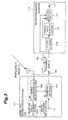
- FIG. 3 is a view showing the functional block configuration of a sending radio station having small EIRP and a receiving radio station according to the first embodiment.
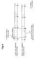
- FIG. 4 is a view showing the timing relationship of the receiving symbol from a sending radio station controlling a certain range of area, and the sending symbol of a sending radio station having small EIRP.
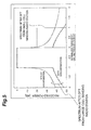
- FIG. 5 is a view of the spectrum from a large cell sending radio station and the spectrum from a small cell sending radio station after DFT in a receiving radio station.
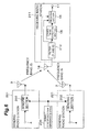
- FIG. 6 is a view of the functional block configuration of a sending radio station and a receiving radio station according to the second embodiment.
- FIG. 7 is a view for describing location registration when moving into the cell of a small cell sending radio station having small EIRP.
- FIG. 8 is an example of the configuration that realizes a symbol synchronization detecting section.
- FIG. 9A is a functional block diagram showing the configuration related to the transmission of OFDM signal in a small cell sending radio station.
- FIG. 9B is a functional block diagram showing the configuration related to the transmission of OFCDM signal in a small cell sending radio station.
- FIG. 10A is a functional block diagram showing the configuration related to the reception of OFDM signal in a receiving radio station.
- FIG. 10B is a functional block diagram showing the configuration related to the reception of OFCDM signal in a receiving radio station.
- FIG. 11 is a flow chart showing an example of the processing of a radio communications program in a sending radio station.
- FIG. 12 is a flow chart showing an example of the processing of a radio communications program in a receiving radio station.
- FIG. 13 is an explanatory view of an example for frequency setting.
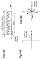
- FIG. 14A is a view showing the copy of the part of OFDM signal.
- FIG. 14B is a view showing the vector when the multiplying timings are identical to each other.
- FIG. 14C is a view showing the vector when the multiplying timings are not identical to each other.
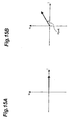
- FIG. 15A is a view showing the vector when the multiplying timings are identical to each other ard the frequency of the local oscillator is identical to the frequency of every sub-carrier signal of the OFDM signal.
- FIG. 15B is a view showing the vector when the multiplying timings are identical to each other and the frequency of the local oscillator is not identical to the frequency of every sub-carrier signal of the OFDM signal.
- the first embodiment of the invention will be described using a view of the functional block configuration of a small cell sending radio station 101 and a receiving radio station 111 in FIG. 3 , and a view showing the timing relationship of the receiving symbol from a large cell sending radio station and the sending symbol of a small cell sending radio station in FIG. 4 .
- a description will be made according to a case where the large cell sending radio station is using a frequency band f1 and the small cell sending radio station is using a frequency band f2.
- a "carrier frequency band” according to the present invention means a carrier frequency or a subcarrier frequency, and the sending radio station can send data by only one carrier.
- a symbol synchronization detection section 105 detects the symbol timing of the data which the large cell sending radio station sends, by receiving signals of the frequency band f1 or a part of the frequency band f1 at the time of turning on the power supply or periodically or continuously.
- a specific method of the detection can be realized by using a generic method to be practiced by a receiving radio station receiving OFDM signal.
- the above mentioned symbol synchronization detection section 105 corresponds to the signal receiving detection means and the symbol synchronization detection means according to the present invention.
- the symbol synchronization detection section 105 can be comprised of, a delay device 301 which effects a delay by a length of one symbol DFT interval for each of the inputted signals of a plurality of different transmission systems, a correlator 302 which carries out the correlation between the guard interval length (GI) using a delayed signal and a non-delayed signal, a maximum correlation value detector 303 for detecting the timing when the correlation value becomes the maximum value, and a timing derivation section 304 which derives the optimum (causing no interference) timing based on the correlation between each of the signals pertaining to a plurality of different transmission systems.
- detection can be performed as follows.
- the timing when the correlation value becomes the maximum value is detected by carrying out the correlation between the guard interval length (GI) using the signal delayed by a length of one symbol DFT interval and non-delayed signal, and then the optimum (causing no interference) timing based on the correlation between each of the signals pertaining to a plurality of different transmission systems, is derived.
- the power and the phase of the signal from the large cell sending radio station are generally considered to be fluctuating in time under the influence of phasing and the like, the accuracy of the symbol synchronization can be improved by averaging the detected timings when the correlation value becomes the maximum value.
- the symbol synchronization detection section 105 outputs the detected timing to a sending section 102.
- the sending section 102 modulates the data inputted from a data input terminal 4, to OFDM transmission signal, and sends the modulated signal by synchronizing with the timing inputted from the symbol synchronization detection section 105.
- the synchronization of the timing is carried out such that no symbol boundary of the signals from the large cell sending radio station exists within one symbol of DFT interval of the signal sent by the small cell sending radio station. Therefore, the amount of the allowable out-of-synchronization is the guard interval length (GI).
- GI guard interval length
- the small cell sending radio station 101 can adopt a configuration that can correspond to not only OFDM transmission but also OFCDM.
- the small cell sending radio station 101 is further comprised of a reception quality measurement section 104 and a spread coefficient set up section 103 as shown with the dashed line in FIG. 3 .
- Such a configuration will be described using FIG. 9B hereinafter.
- the configuration related to the transmission of OFDM signal in the small cell sending radio station 101 is shown in FIG. 9A .
- the symbol synchronization detection section 105 shown in FIG.9A has such a configuration as the above mentioned in FIG. 8 , wherein the symbol synchronization is derived from the received signal from a large cell sending radio station such that the symbol boundary of the signal from the large cell sending base station does not exist in the DFT interval of one symbol.
- a sending carrier set up section 102A sets up a subcarrier to be sent based on the number of sending carriers and the operating condition of the subcarrier given from the control signal from a control section (not shown).
- the symbol sequence supposed to be sent by a sending radio station of a lower level cell (meaning a "sending radio station of a lower level cell in the hierarchical cell structure", and corresponding to the small cell sending station in FIG. 1 ), will be serial/parallel (S/P) converted by a serial/parallel conversion section 102B to the parallel data of all or a part of the number of the subcarrier based on the set up carrier information.
- the symbol sequence converted to the parallel data will be time/frequency converted by inverse FFT (IFFT) processing by an IFFT section 102C, to multi-carrier components that are orthogonal in the frequency axis.
- IFFT inverse FFT
- GI guard interval
- the above mentioned GI insertion section 102D outputs the modulated signal to a symbol transmission control section 102E, and the above mentioned symbol transmission control section 102E sends the modulated symbol sequence at the symbol synchronization timing that is outputted from the symbol synchronization detection section 105.
- FIG. 9B A configuration related to the transmission of OFCDM signal in the small cell sending radio station 101 is shown in FIG. 9B .
- the symbol synchronization detection section 105 shown in FIG. 9B has such a configuration as the above mentioned of FIG. 8 , wherein the symbol synchronization is derived from the received signal from the large cell sending radio station such that no symbol boundary of the signal from the large cell sending base station exists within the DFT interval of one symbol.
- the received signal from the large cell sending radio station is also inputted to a reception quality measurement section 104 where the reception quality is measured.
- a spread-coefficient set up section 103 judges whether the signal supposed to be sent by the sending radio station of a lower level cell is spread or not, and when having judged to be spread, the spread coefficient will be set up, and the signal is outputted to a spread code generation section 102F.
- the spread code generation section 102F assigns the spread code from the spread coefficient set up.
- the symbol sequence (sending signal) supposed to be sent by the small cell sending radio station 101 is inputted to a multiplex section 102G, and pilot bits for the channel estimation are multiplexed by the multiplex section 102G.
- the sending carrier set up section 102A sets up the subcarrier to be sent, based on the spread coefficient from the spread-coefficient set up section 103 as well as the number of the sending carrier and the operating condition of the subcarrier provided from the control section (not shown).
- the serial/parallel conversion section 102B serial/parallel (S/P) converts the above mentioned symbol sequence to the parallel data (all or a part of the number of the subcarrier/spread coefficient) based on the carrier information set up.
- the symbol sequence converted into the parallel data by the above mentioned serial/parallel conversion will be copied by a copy section 102H in the continuous subcarrier and time axis, from the relationship between the number of spread coefficients (SF) and the number of subcarrier. Specifically, when the spread coefficient SF is larger than the number of subcarrier, the symbol will be copied in the subcarrier and the time axis, and when the spread coefficient SF is smaller than the number of subcarrier, the symbol will be copied into a part of the subcarrier. At this time, the copy of the same symbols of SF pieces into the subcarriers can be implemented by repeatedly reading the symbol sequence that has been inputted into a memory.
- the same symbol sequence of SF pieces will be spread (scrambled) by a composing section 102I according to the uniquely assigned spread code of the spread coefficient SF.
- the dimension pertaining to FFT processing is determined according to the number of subcarriers that are inputted by means of the control signal, and the spread symbol sequence corresponding to the number of subcarriers will be time/frequency converted by inverse FFT (IFFT) processing by IFFT section 102C, into the multi-carrier components orthogonal on the frequency axis.
- IFFT inverse FFT
- the guard interval is inserted in the symbol of each subcarrier that has been converted into the multi-carrier, by the guard interval insertion section 102D.
- the insertion of this guard interval is implemented by copying the signal waveform corresponding to FFT samples of the last of each symbol or within the symbol sequence, to the top of each symbol. Then, the above mentioned GI insertion section 102D outputs the modulated signal to the symbol transmission control section 102E, and the above mentioned symbol transmission control section 102E sends the modulated symbol sequence at the symbol synchronization timing that is outputted from the symbol synchronization detection section 105.
- the signal from an antenna 16 is inputted to a symbol timing detection section 18 through a filter 112 which passes both the frequency bands of the frequency band f1 and the frequency band f2, and the symbol timing (the timing when FFT processing is carried out, and also called "FFT window timing") is detected from the received multi-carrier signal.
- the filter 112 is used in order to cut off the radio waves from other systems difficult of synchronization.
- the signals of the frequency band f1 and the frequency band f2 having passed the filter 112 will be demodulated respectively, after DFT (Discrete Fourier Transform) processing of both the frequency bands together is carried out in the receiving section 15.
- DFT Discrete Fourier Transform
- the signal demodulated by the receiving section 15 is outputted from a data output terminal 17.
- the data to be outputted at this time can be formed into the data to be transmitted by the frequency band f1 only, the frequency band f2 only or the frequency bands f1 and f2. Namely, since signals of a plurality of frequency bands can be simultaneously received according to the present invention, a smooth hand-over can be carried out.
- the interference can be reduced by carrying out the synchronization of the symbol as described above, whereby the signals from the large cell sending radio station and the small cell sending radio station can be simultaneously demodulated.
- the configuration of the receiving radio station 111 (especially, the receiving section 15) will be described in more detail.
- FIG. 10A The configuration related to the transmission of OFDM signal in the receiving radio station 111 is shown in FIG. 10A .
- the received signal from a large cell sending radio station is inputted to the symbol timing detection section 18 through the filter 112 which passes both the frequency bands of the frequency band f1 and the frequency band f2 (each frequency band fn in case of reception of three frequency bands or more from a large cell sending radio station), and the symbol timing (the timing when FFT processing is carried out, and also called "FFT window timing") is detected from the received multi-carrier signal.
- the detection of this symbol timing can be carried out by the detection of the correlation between the guard interval length.
- a guard interval removal section 15A removes the signal of the guard interval from the symbol timing detected by the symbol timing detection section 18 as mentioned above. Then, Discrete Fourier Transform (DFT) is carried out, for the removed signal by an FFT section 15B at the estimated FFT window timing, and then the signal is parallel/serial (P/S) converted into the parallel signal in a parallel/serial-conversion section 15G and inputted to a demodulation section 15D.
- a demodulation section 15D can be constituted in such a manner as to select some signals from the signals of the plurality of carrier frequency bands pertaining to different transmission systems and demodulate the signals.
- the purpose of the above mentioned filter 112 is to remove the signals of the frequency bands except for the signals of the plurality of frequency bands desired to be simultaneously received.
- signals except for the required frequency bands can be removed by selecting the frequency band of the signals from a specific sending radio station.
- the filter 112 will set up the frequency bands to be filtered by means of the control signal from the control section (not shown), wherein furthermore, the frequency band subject to FFT processing varies, so that the FFT processing of the required frequency bands can be carried out by notifying the FFT section 15B of the dimension pertaining to the cross-correlation carried out by the above mentioned control signal.
- FIG. 10B A configuration related to the transmission of OFCDM signal in the receiving radio station 111 is shown in FIG. 10B .
- the received signal from the large cell sending radio station is inputted to the symbol timing detection section 18 through the filter 112 which passes both the frequency bands of the frequency band f1 and the frequency band f2 (each frequency band fn in case of reception of three or more frequency bands the large cell sending radio station), and the symbol timing (the timing when FFT processing is carried out, and also called "FFT window timing") is detected from the received multi-carrier signal.
- the detection of this symbol timing can be carried out by the detection of the correlation between the guard interval length.
- the guard interval removal section 15A removes the signal of the guard interval from the symbol timing detected by the symbol timing detection section 18 as mentioned above. Then, Discrete Fourier Transform (DFT) is carried out to the removed signal by the FFT section 158 at the estimated FFT window timing, and the channel impulse response (channel fluctuation) of each subcarrier is estimated by a channel estimation section 15E by using a pilot symbol.
- An in-phase summation section 15G carries out in-phase summation (namely, inverse spread) on the frequency axis, of OFCDM symbol of the subcarrier component of SF pieces from the spread codes which has been used for the channel estimation value of each of this subcarrier and the spread, and thereby generates an information symbol sequence.
- the information symbols of the inverse spread (the total number of subcarriers/spread coefficient) pieces are parallel/serial (P/S) converted by a parallel/serial conversion section 15C, and inputted to the demodulation section 15D.
- the demodulation section 15D can be constituted in such a manner as to select some signals from the signals of a plurality of carrier frequency bands pertaining to different transmission systems and demodulate the signals.
- the purpose of the above mentioned filter 112 is to remove the signals of the frequency bands except for the signals of a plurality of frequency bands desired to be simultaneously received.
- signals except for the required frequency bands can be removed by selecting the frequency band of the signals from a specific sending radio station.
- the filter 112 will set up the frequency bands to be filtered by means of the control signal from the control section (not shown), wherein furthermore, the frequency band subject to FFT processing varies, so that the FFT processing of the required frequency bands can be carried out by notifying the FFT section 15B of the dimension pertaining to the cross-correlation carried out by the above mentioned control signal.
- the processing in the sending radio station and the receiving radio station of the above-mentioned embodiment is also to be interpreted as the processing of a radio communications program executed by a computer provided in each radio station.
- the processing in the sending radio station ( FIG. 11 ) and the processing in the receiving radio station ( FIG. 12 ) will be described in due order.
- the outline of the processing in the sending radio station can be expressed as shown in FIG. 11 .
- the sending radio station monitors whether one or more carrier frequency band signals of a transmission system other than that of the station of its own has been received or not (S01: signal detection step), and when the reception of the carrier frequency band signal of a different transmission system is detected, the sending symbol synchronization will be detected from the received signal (SO2: symbol synchronization detection step). Then, based on the detected symbol synchronization, the symbol sending timing when the carrier frequency band signal pertaining to the different transmission system and the signal from the station of its own do not interfere with each other, will be derived, and the signal to be sent at the symbol sending timing, will be sent (SO3: signal sending step).
- the receiving radio station registers an information indicating that the receiving radio station is ready for receiving the signal from the large cell sending radio station and ready for receiving the signal from a small cell sending radio station, to network data transfer device (for example, a location registration management server which implements the location registration of a receiving radio station in the network, or a router in the network, or the like) (S11: registration step).
- network data transfer device for example, a location registration management server which implements the location registration of a receiving radio station in the network, or a router in the network, or the like
- the data transfer device selects the sending radio station, which sends the data according to the classification of the data to be sent to the receiving radio station.
- the data transmission control corresponding to the classification of the data can be carried out.
- multicasting information is sent from a large cell sending radio station to the receiving radio station, and individual information of high data rate such as image data is sent from a small cell sending radio station to the receiving radio station.
- a judgment for the above-mentioned matter in such a manner that the selection of the sending radio station can be judged corresponding to the amount of data and the traffic characteristics (for example, in non-real time or real time) can be performed. Therefore, the invention is not limited to the above-mentioned embodiment.
- the receiving radio station which has received the signals of such plurality of carrier frequency bands, simultaneously received the signals and demodulated the signals (312: simultaneous receiving step).
- the receiving radio station when the receiving radio station has moved into a place where the signal from a small cell sending radio station can be received, the receiving radio station will notify the above mentioned data transfer device of having moved into the cell of a small cell sending radio station #3, through a large cell sending radio station #1 or a small cell sending radio station #3. Thereby the receiving radio station can always receive the data from the large cell sending radio station and from the small cell sending radio station, when the receiving radio station is located in the cell of this small cell sending radio station.
- the multicasting information can be sent from the large cell sending radio station, while in case of the transmission of a large capacity of information to a specific receiving radio station, the large capacity of information can be independently sent from the small cell sending radio station, respectively.
- the processing in the sending radio station and the receiving radio station according to the embodiment can be interpreted as the processing of a radio communications program executed by a computer provided in each radio station.
- the set up of the DFT interval in the receiving radio station is synchronized with the signal from the small cell sending radio station. Moreover, no guard band is provided between the frequency bands used by the large cell sending radio station and the frequency band used by the small cell sending radio station. Namely, the interval of all subcarrier frequencies is identical. Since the cell radius of the large cell is larger than the cell radius of the small cell, the Equivalent Isotropically Radiated Power (EIRP) of the large cell sending radio station is larger than the EIRP of the small cell sending radio station. Therefore, in the receiving radio station located in the small cell which exists near the large cell sending radio station, as shown in FIG. 5 , the radio wave from the large cell sending radio station is received with higher power.
- EIRP Equivalent Isotropically Radiated Power
- the spectrum of a rectangle shape shown at the normalized frequency of 0 to 1 is the spectrum after DFT processing of the signal from the small cell sending radio station
- the spectrum of a rectangle shape shown at the normalized frequency of -1 to 0 is the spectrum after the DFT processing of the signal from the large cell sending radio station.
- a synchronization request means requesting the symbol synchronization from the sending radio station in a receiving radio station and a sending radio station carries out the symbol synchronization detection and the sending timing control triggered upon the request of the symbol synchronization from the synchronization request means of the receiving radio station.
- the receiving radio station can simultaneously receive the signals of a plurality of carrier frequency bands and demodulate the signals, the "change processing of frequency" like in the prior art at the time of the hand-over is not needed, whereby a smooth hand-over can be achieved.
- the guard band can be set small or can be made unnecessary, the frequency can be effectively utilized.
- the multi-link transmission can be carried out.
- new sending radio stations can be freely arranged without much taking into consideration the influence of interference on other existing sending radio stations forming the small cell.
- the components for receiving of the receiving radio station can be shared, the reduction of capacity of the receiving radio station as well as the reduction of manufacturing cost can be achieved.
- the sending radio station is not limited to the base station but can be a mobile station.
- the synchronization request means of a mobile station requests the symbol synchronization to another mobile station (corresponding to the sending radio station), and another mobile station will carry out the symbol synchronization detection and sending timing control. Thereby autonomous sending timing control between the mobile stations can be achieved.
- the accuracy (stability) of the symbol synchronization by the small cell sending radio station is considered to be higher than the accuracy (stability) of the symbol synchronization by the receiving radio station, since the small cell sending radio station is fixedly installed, its antenna gain is higher than that at the receiving radio station, and the installation environment of the antenna of the small cell sending radio station is better than the installation environment of the antenna of the receiving radio station. Moreover, it is assumed that on relatively many occasions there will be a environment with better line of sight communication between the small cell sending radio station and the receiving radio station as compared with that between the large cell sending radio station and the receiving radio station.
- the accuracy (stability) of the symbol synchronization in the receiving radio station is higher in the case where the symbol synchronization is carried out associated with the small cell sending radio station, than in the case where the symbol synchronization is carried out associated with the large cell sending radio station.
- the receiving radio station can receive the signals from the large cell sending radio station more stably by carrying out the symbol synchronization associated with the small cell sending radio station (namely, the symbol can be equivalently synchronized associated with the large cell, by the symbol synchronization associated with the small cell sending radio station).
- the second embodiment will be described using a view of the functional block configuration of the sending radio station and the receiving radio station of FIG. 6 .
- This embodiment will be described as a case where a sending radio station uses a frequency band f3 and another sending radio station uses a frequency band f4.
- the sending radio station can be applied to both a large cell sending radio station and a small cell sending radio station.
- two frequency bands are used will be described, such descriptive explanation is also adapted to the case wherein three or more frequency bands are used.
- a sending section 202 of a sending radio station 201 and a sending section 202 of a sending radio station 221 will carry out the symbol synchronization for the sending symbols by means of the signal that is outputted from a symbol synchronization reference source 230. Namely, the data inputted from the data input terminal 4 of the sending radio station 201 and the data inputted from the data input terminal 4 of the sending radio station 221 will be sent such that the symbols thereof are synchronized with each other. As shown in FIG. 4 , the synchronization of the symbol at this time is carried out such that no symbol boundary of the signal to be sent by another sending radio station exists in the DFT interval of one symbol.
- a synchronization request means corresponds to "a synchronization request means" according to the invention.
- the symbol synchronization reference is independently prepared in this description, there can be adopted a method other than this, wherein the symbol synchronization reference is prepared in either one of sending radio stations, and sending radio stations without the symbol synchronization reference are synchronized with the sending radio station having the symbol synchronization reference.
- the symbol synchronization references in all the sending radio stations, and the symbol synchronization is carried out by means of mutual linking between the symbol synchronization reference of the station of its own and the symbol synchronization reference of other sending radio stations via a cable or radio.
- each sending radio station links with each other to set up such that the sending carrier frequency of the signal to be sent by each sending radio station becomes orthogonal to each other.
- the sending radio station when the sending radio station is equipped with a frequency interval detection means for detecting the frequency interval based on the received signal from another sending radio station, and a frequency set up means for setting up the sending carrier frequency, based on the detected frequency interval, so as to acquire an orthogonal relationship with respect to the sending carrier frequency of the sending radio station, the sending radio station can send signals at the optimum (namely, causing no interference with each other) symbol sending timing by the correlation between the carrier frequency band signal of a transmission system other than that of the own station and the signal of the station of its own. An example of setting up the frequency will be described afterwards.
- the signal from the antenna 16 is inputted to the receiving section 15 through the filter 112 that passes both the frequency bands of the frequency band f3 and the frequency band f4 in the receiving radio station 211. Then, the signal that is DFT transformed and demodulated by the receiving section 15 will be outputted from a data output terminal 17.
- the data to be outputted at this time can be formed into the data to be transmitted by the frequency band f3 only, the frequency band f4 only, or the frequency bands f3 and f4.
- the sending radio station can send signals at the optimum (namely, causing no interference with each other) symbol sending timing by the correlation between the carrier frequency band signal of a transmission system other than that of the own station and the signal of the station of its own.
- the receiving radio station can simultaneously receive signals of a plurality of carrier frequency bands and demodulate the signals. Therefore, there will be no need to carry out the "frequency switch over process" like in the prior art at the time of hand-over, thereby a smooth hand-over can be achieved.
- the guard band can be set up small and can be made unnecessary, the frequency can be effectively utilized.
- signals from a plurality of sending radio stations can be simultaneously received, the multi-link transmission can be carried out.
- new sending radio stations can be freely arranged without much taking into consideration the influence of interference on other existing sending radio stations forming a small cell.
- the components for receiving of the receiving radio station which receive signals of the plurality of frequency bands can be shared, the reduction of capacity of the receiving radio station and the reduction of manufacturing cost can be achieved.
- the received signal from other sending radio station such as a large cell sending radio station is multiplied with the signal from a local oscillator 317 by each of the multipliers 311A, 311B, and each multiplied signal is converted to the baseband signal (r I ,r Q ) by each of the lowpass filters 312A, 312B (the ( ⁇ /2) phase-converted signal is input into the multiplier 311B).
- Each of the baseband signal (r I ,r Q ) is converted to the delayed baseband signal (r -I ,r -Q ) by each of the delay devices 313A, 313B.
- each of the non-delayed baseband signal (r I ,r Q ) and each of the delayed baseband signal (r -I ,r -Q ) are multiplied with each other and the multiplied signals are added.
- This transaction corresponds to the transaction for multiplying the complex conjugate of the delayed complex vector with the non-delayed complex vector.
- the result will be a vector which fluctuates as time elapses on the complex plane as shown in Fig. 14C . Accordingly, the integration for the vectors on the same phase is not done, so the length of the integrated vector will become smaller than the pre-determined threshold.
- the timing when the length of the integrated vector is larger than the threshold and the length is the maximum value, will be the symbol timing for DFT.
- ⁇ f[Hz] means the minimum value of the difference between the frequency of the local oscillator 317 and the frequency of each sub-carrier signal of the OFDM signal
- ⁇ [radian] means the angle of deviation of the integrated vector
- T[sec] means the delayed time (DFT interval of one symbol) set for the delay devices 313A, 313B.
- the frequencies will be synchronized by amending the local oscillator 317 for the difference between the frequencies detected. Since the status where the frequencies are synchronized is the status where the local oscillator 317 of the sending radio station itself synchronized with the sending frequency of the signal from other sending radio station, the relationship between the sending carrier frequencies of the signals from the sending radio stations proves to be an orthogonal relationship by using the local oscillator 317 for the sending frequency of the signal which the sending radio station itself sends.
- the small cell sending radio station in the first and the second embodiments can be a wireless LAN, and can be other radio communications network in a small area.
- the sending radio station can send signals at the optimum (namely, causing no interference with each other) symbol sending timing by the correlation between the carrier frequency band signal of a transmission system other than that of the station of its own and the signal of the station of its own. Accordingly, since the receiving radio station can simultaneously receive signals of a plurality of carrier frequency bands and demodulate the signals, there will be no need to carry out the "frequency switch over process" like in the prior art at the time of hand-over, thereby a smooth hand-over can be achieved.
- the guard band can be set small or can be made unnecessary, the frequency can be effectively utilized.
- signals from a plurality of sending radio stations can be simultaneously received, the multi-link transmission can be carried out.
- new sending radio stations can be freely arranged without much taking into consideration the influence of interference of other existing sending radio stations forming the small cell.
- the components for receiving of the receiving radio station which receive signals of the plurality of frequency bands can be shared, the reduction of capacity of the receiving radio station and the reduction of manufacturing cost can be achieved.
- a sending radio station to arrange symbols to be sent in the frequency axis and send signals to a radio terminal inside the area using one or a plurality of carrier frequency bands may be provided in a radio communication system with a hierarchical cell structure.
- the sending radio station may include: a signal detection means for detecting at least one carrier frequency band signal being pertaining to a transmission system other than that of its own station; a symbol synchronization detection means for detecting sending-symbol synchronization based on at least one received signal on detecting the carrier frequency band signal pertaining to the transmission system other than that of its own station; and a signal sending means for sending the signal to be sent, based on the symbol sending timing derived based on the detected symbol synchronization.
- the sending radio station may furthermore include a frequency interval detection means for detecting the frequency interval based on the received signal from a radio terminal, and a frequency set up means for setting up the sending carrier frequency, based on the detected frequency interval, so as to acquire an orthogonal relationship with respect to the sending carrier frequency of the radio terminal.
- the sending radio station may furthermore include a reception quality measurement means to measure reception quality based on the received signal from the radio terminal, and a spread coefficient set up means to set up a spread coefficient based on the reception quality obtained by the measurement.
- a receiving radio station to receive signals from a sending radio station for arranging symbols to be sent in the frequency axis and sending signals to a radio terminal inside the area using one or a plurality of carrier frequency bands, and to locate in a radio communication system with a hierarchical cell structure.
- the receiving radio station may have a simultaneous reception control means for simultaneously receiving signals of a plurality of carrier frequency bands and demodulating the signals.
- the receiving radio station may furthermore include a registration means, wherein when the station of its own moves into a small scale cell in the hierarchical cell structure, the registration means may register an information to a data transfer system in the radio communication system, the information indicating that the station of its own is ready for receiving signal from the sending radio station of a large scale cell controlling the area, and ready for receiving signal from the sending radio station of the small scale cell.
- the simultaneous reception control means may select signals of at least one carrier frequency band pertaining to another transmission system, and may demodulate the signals.
- a radio communication system with a hierarchical cell structure may be provided.
- the radio communication system may include a sending radio station to arrange symbols to be sent in the frequency axis and send signals to a radio terminal inside the area using one or a plurality of carrier frequency bands, and a receiving radio station which receives the signals from the sending radio station.
- the sending radio station may include: a signal detection means for detecting at least one carrier frequency band signal being pertaining to a transmission system other than that of its own station; a symbol synchronization detection means for detecting sending-symbol synchronization based on at least one received signal on detecting the carrier frequency band signal pertaining to the transmission system other than that of its own station; a signal sending means for sending the signal to be sent, at the symbol sending timing derived based on the detected symbol synchronization.
- the receiving radio station may include a simultaneous reception control means for simultaneously receiving the signals of a plurality of carrier frequency bands and demodulating the signals.
- the radio communication system may include a plurality of sending radio stations using a plurality of different carrier frequency bands.
- the plurality of sending radio stations may link each other over a cable or radio, and each sending radio station may synchronously send symbols of the signals to be sent.
- the plurality of sending radio stations may link each other to set up such that the sending carrier frequency of the signal to be sent by each sending radio station becomes orthogonal to each other.
- a radio communication system with a hierarchical cell structure may be provided.
- the radio communication system may include a sending radio station to arrange the symbol to be sent in the frequency axis and send signals to a radio terminal inside the area using one or a plurality of carrier frequency bands, and a receiving radio station which may receive the signals from the sending radio station.
- the receiving radio station may include: a synchronization request means for requesting symbol synchronization to the sending radio station, and a simultaneous reception control means for simultaneously receiving the signals of a plurality of carrier frequency bands and demodulating the signals.
- the sending radio station may include: a symbol synchronization detection means for detecting the sending symbol synchronization based on at least one received signal when a request of the symbol synchronization is received from the receiving radio station, and a signal sending means for sending the signal to be sent, at the symbol sending timing derived based on the detected symbol synchronization.
- a radio communication method applicable in a sending radio station to arrange symbols to be sent in the frequency axis and send signals to the radio terminal inside the area using one or a plurality of carrier frequency bands may be provided in the radio communication system with a hierarchical cell structure.
- the radio communication method may include: a signal detection step wherein the sending radio station may detect at least one carrier frequency band signal of a transmission system other than that of its own station; a symbol synchronization detection step wherein the sending radio station may detect the sending symbol synchronization based on at least one received signal, on detecting the carrier frequency band signal pertaining to the transmission system other than that of its own station; a signal sending step wherein the sending radio station may send signals to be sent, at the symbol sending timing derived based on the detected symbol synchronization.
- a radio communication method in a radio communication system with a hierarchical cell structure may include a sending radio station to arrange symbols to be sent in the frequency axis and send signals to a radio terminal inside the area using one or a plurality of carrier frequency bands, and a receiving radio station to receive signals from the sending radio station.
- the radio communication method may include: a synchronization request step wherein the receiving radio station may request the symbol synchronization to the sending radio station; a symbol synchronization detection step wherein the sending radio station may detect the sending symbol synchronization based on at least one received signal, when the sending radio station receives a request of the symbol synchronization from the receiving radio station; and a signal sending step wherein the sending radio station may send signals to be sent, at the symbol sending timing derived based on the detected symbol synchronization.
Applications Claiming Priority (2)
| Application Number | Priority Date | Filing Date | Title |
|---|---|---|---|
| JP2003025013 | 2003-01-31 | ||
| EP04002179A EP1443682B1 (fr) | 2003-01-31 | 2004-01-30 | Synchronisation de transmission |
Related Parent Applications (1)
| Application Number | Title | Priority Date | Filing Date |
|---|---|---|---|
| EP04002179.2 Division | 2004-01-30 |
Publications (1)
| Publication Number | Publication Date |
|---|---|
| EP2224612A1 true EP2224612A1 (fr) | 2010-09-01 |
Family
ID=32652939
Family Applications (2)
| Application Number | Title | Priority Date | Filing Date |
|---|---|---|---|
| EP10157747A Withdrawn EP2224612A1 (fr) | 2003-01-31 | 2004-01-30 | Système et procédé de radio pour la récéption simultanée de signaux |
| EP04002179A Expired - Fee Related EP1443682B1 (fr) | 2003-01-31 | 2004-01-30 | Synchronisation de transmission |
Family Applications After (1)
| Application Number | Title | Priority Date | Filing Date |
|---|---|---|---|
| EP04002179A Expired - Fee Related EP1443682B1 (fr) | 2003-01-31 | 2004-01-30 | Synchronisation de transmission |
Country Status (4)
| Country | Link |
|---|---|
| US (1) | US7457230B2 (fr) |
| EP (2) | EP2224612A1 (fr) |
| CN (1) | CN1297077C (fr) |
| DE (1) | DE602004027322D1 (fr) |
Cited By (1)
| Publication number | Priority date | Publication date | Assignee | Title |
|---|---|---|---|---|
| US8238319B2 (en) | 2006-09-01 | 2012-08-07 | Advanced Telecommunications Research Institute International | Radio apparatus |
Families Citing this family (17)
| Publication number | Priority date | Publication date | Assignee | Title |
|---|---|---|---|---|
| ES2212744B2 (es) * | 2003-01-10 | 2005-03-16 | Diseño De Sistemas En Silicio, S.A. | Procedimiento de sincronizacion en el dominio del tiempo y de la frecuencia de multiples equipos en un sistema de transmision con modulacion ofdm. |
| JP4437817B2 (ja) * | 2004-06-18 | 2010-03-24 | 三菱電機株式会社 | 自律的セル形成方法 |
| WO2006051587A1 (fr) | 2004-11-10 | 2006-05-18 | Fujitsu Limited | Appareil de sélection de cellule et méthode de sélection de cellule |
| WO2006125738A1 (fr) * | 2005-05-23 | 2006-11-30 | Nokia Siemens Networks Gmbh & Co. Kg | Procede pour selectionner des bandes de frequences appropriees pour la transmission de donnees entre un noeud reseau et un equipement utilisateur dans un reseau de communication mobile |
| US8730877B2 (en) | 2005-06-16 | 2014-05-20 | Qualcomm Incorporated | Pilot and data transmission in a quasi-orthogonal single-carrier frequency division multiple access system |
| US8315191B2 (en) * | 2005-09-20 | 2012-11-20 | Qualcomm Incorporated | Timing acquisition and mode and guard detection for an OFDM transmission |
| US8599940B2 (en) * | 2006-09-26 | 2013-12-03 | Nokia Corporation | Apparatus, method and computer program product providing sequence modulation for uplink control signaling |
| PL2070217T3 (pl) * | 2006-09-26 | 2020-10-05 | Nokia Technologies Oy | Urządzenie, sposób i produkt programu komputerowego zapewniające multipleksowanie kanału kontrolnego niezwiązanego z danymi |
| GB0619530D0 (en) | 2006-10-03 | 2006-11-15 | Nokia Corp | Signalling |
| CN103220113B (zh) * | 2006-12-22 | 2017-02-22 | 富士通株式会社 | 无线通信方法及基站和用户终端 |
| WO2009016688A1 (fr) * | 2007-08-02 | 2009-02-05 | Fujitsu Limited | Dispositif de communication sans fil |
| CN101803255B (zh) * | 2007-09-12 | 2013-11-20 | 夏普株式会社 | 无线通信方法、无线通信系统和无线发送装置 |
| KR20130075345A (ko) * | 2011-12-27 | 2013-07-05 | 삼성전자주식회사 | 무선 단말장치에서 근거리 통신 연결 제어장치 및 방법 |
| US9203676B1 (en) * | 2014-06-11 | 2015-12-01 | Wipro Limited | Apparatus and method for estimating symbol timing offset |
| EP3086478B1 (fr) * | 2015-04-23 | 2018-09-19 | Nxp B.V. | Récepteur sans fil et procédé |
| US9923584B2 (en) * | 2015-09-03 | 2018-03-20 | Qualcomm Incorporated | Rectifiers for wireless power transfer with impedance inverting filters for reduced electromagnetic interference |
| JP2019083427A (ja) * | 2017-10-31 | 2019-05-30 | 株式会社日立製作所 | 無線通信システムおよび無線監視制御システム |
Citations (5)
| Publication number | Priority date | Publication date | Assignee | Title |
|---|---|---|---|---|
| JPH07283806A (ja) | 1994-04-13 | 1995-10-27 | Nippon Hoso Kyokai <Nhk> | 直交周波数分割多重変調信号伝送方式 |
| JPH10290211A (ja) | 1996-06-19 | 1998-10-27 | N T T Ido Tsushinmo Kk | Cdma通信方法およびグループ拡散変調器 |
| EP1187387A1 (fr) * | 2000-09-08 | 2002-03-13 | Alcatel | Recépteur GSM multiporteuse |
| US6430168B1 (en) * | 1999-10-18 | 2002-08-06 | Nortel Networks Limited | CDMA base station lantern application |
| EP1231805A1 (fr) * | 2001-01-31 | 2002-08-14 | Lucent Technologies Inc. | Système et procédé de transfert intercellulaire entre couches d'un système cellulaire hiérarchique |
Family Cites Families (22)
| Publication number | Priority date | Publication date | Assignee | Title |
|---|---|---|---|---|
| US648173A (en) * | 1899-02-23 | 1900-04-24 | Emil B Meyrowitz | Ophthalmometer. |
| GB2135804A (en) * | 1982-11-17 | 1984-09-05 | Philips Electronic Associated | Alpha numeric display device and visual display arrangement employing such display devices |
| GB2313984B (en) | 1993-06-02 | 1998-01-28 | Vtech Communications Ltd | Interface protocol method and apparatus |
| JPH09312874A (ja) | 1996-03-19 | 1997-12-02 | Canon Inc | 無線通信装置、無線通信システム及びそれらの制御方法 |
| US5875179A (en) * | 1996-10-29 | 1999-02-23 | Proxim, Inc. | Method and apparatus for synchronized communication over wireless backbone architecture |
| US6038450A (en) | 1997-09-12 | 2000-03-14 | Lucent Technologies, Inc. | Soft handover system for a multiple sub-carrier communication system and method thereof |
| EP0954122A1 (fr) * | 1998-04-28 | 1999-11-03 | Siemens Aktiengesellschaft | Méthode pour la gestion d'un système de communication radio et tel système |
| FR2778518A1 (fr) | 1998-05-11 | 1999-11-12 | Inst Nat Rech Inf Automat | Installation de transmission de donnees a stations relais synchronisees, et procede correspondant |
| US20020082019A1 (en) * | 1998-12-30 | 2002-06-27 | Oguz Sunay | Methods and apparatus for accomplishing inter-frequency, inter-network, and inter-tier soft handoff using dual transmission/reception or compression |
| WO2000051366A2 (fr) | 1999-02-26 | 2000-08-31 | Telefonaktiebolaget Lm Ericsson (Publ) | Signaux horodateurs utilisant les canaux communs de signalisation dans un reseau cellulaire de telecommunications |
| JP2000295198A (ja) | 1999-04-01 | 2000-10-20 | Matsushita Electric Ind Co Ltd | Cdma基地局装置及びcdma通信方法 |
| US6493539B1 (en) | 1999-07-28 | 2002-12-10 | Lucent Technologies Inc. | Providing an accurate timing source for locating the geographical position of a mobile |
| EP1079576A3 (fr) | 1999-08-25 | 2003-05-07 | Matsushita Electric Industrial Co., Ltd. | Récepteur multiporteuse à extraction directe d'un signal de contrôle |
| EP1148659B1 (fr) * | 2000-04-18 | 2005-07-27 | Sony International (Europe) GmbH | Transmission OFDM en diversité |
| WO2001097478A2 (fr) * | 2000-06-13 | 2001-12-20 | At & T Wireless Services, Inc. | Procedes et appareil d'obtention de synchronisation de trames dans un systeme de communication de multiplexage par repartition en frequence orthogonale |
| US7039027B2 (en) * | 2000-12-28 | 2006-05-02 | Symbol Technologies, Inc. | Automatic and seamless vertical roaming between wireless local area network (WLAN) and wireless wide area network (WWAN) while maintaining an active voice or streaming data connection: systems, methods and program products |
| US6785513B1 (en) * | 2001-04-05 | 2004-08-31 | Cowave Networks, Inc. | Method and system for clustered wireless networks |
| JP2002335556A (ja) | 2001-05-08 | 2002-11-22 | Sony Corp | 無線通信システムおよびその方法 |
| US6829481B2 (en) * | 2001-05-15 | 2004-12-07 | Novatel Wireless, Inc. | Systems and methods for intelligent inter-system handoff |
| GB0117071D0 (en) * | 2001-07-13 | 2001-09-05 | Koninkl Philips Electronics Nv | Hierarchical cellular radio communication system |
| KR20040011653A (ko) * | 2002-07-29 | 2004-02-11 | 삼성전자주식회사 | 채널 특성에 적응적인 직교 주파수 분할 다중 통신 방법및 장치 |
| EP1605619A4 (fr) * | 2003-02-28 | 2012-01-11 | Ntt Docomo Inc | Systeme et procede de radiocommunication |
-
2004
- 2004-01-30 DE DE602004027322T patent/DE602004027322D1/de not_active Expired - Lifetime
- 2004-01-30 EP EP10157747A patent/EP2224612A1/fr not_active Withdrawn
- 2004-01-30 US US10/767,370 patent/US7457230B2/en not_active Expired - Fee Related
- 2004-01-30 EP EP04002179A patent/EP1443682B1/fr not_active Expired - Fee Related
- 2004-01-30 CN CNB2004100037623A patent/CN1297077C/zh not_active Expired - Fee Related
Patent Citations (5)
| Publication number | Priority date | Publication date | Assignee | Title |
|---|---|---|---|---|
| JPH07283806A (ja) | 1994-04-13 | 1995-10-27 | Nippon Hoso Kyokai <Nhk> | 直交周波数分割多重変調信号伝送方式 |
| JPH10290211A (ja) | 1996-06-19 | 1998-10-27 | N T T Ido Tsushinmo Kk | Cdma通信方法およびグループ拡散変調器 |
| US6430168B1 (en) * | 1999-10-18 | 2002-08-06 | Nortel Networks Limited | CDMA base station lantern application |
| EP1187387A1 (fr) * | 2000-09-08 | 2002-03-13 | Alcatel | Recépteur GSM multiporteuse |
| EP1231805A1 (fr) * | 2001-01-31 | 2002-08-14 | Lucent Technologies Inc. | Système et procédé de transfert intercellulaire entre couches d'un système cellulaire hiérarchique |
Cited By (1)
| Publication number | Priority date | Publication date | Assignee | Title |
|---|---|---|---|---|
| US8238319B2 (en) | 2006-09-01 | 2012-08-07 | Advanced Telecommunications Research Institute International | Radio apparatus |
Also Published As
| Publication number | Publication date |
|---|---|
| EP1443682B1 (fr) | 2010-05-26 |
| EP1443682A3 (fr) | 2004-11-24 |
| US7457230B2 (en) | 2008-11-25 |
| DE602004027322D1 (de) | 2010-07-08 |
| US20040258098A1 (en) | 2004-12-23 |
| EP1443682A2 (fr) | 2004-08-04 |
| CN1525659A (zh) | 2004-09-01 |
| CN1297077C (zh) | 2007-01-24 |
Similar Documents
| Publication | Publication Date | Title |
|---|---|---|
| EP1443682B1 (fr) | Synchronisation de transmission | |
| KR100260863B1 (ko) | 중첩하는 상향접속 반송파 스펙트럼을 갖는 복수 사용자 통신 시스템, 장치 및 방법 | |
| US7852813B2 (en) | System and method for acquiring cell in a frequency overlay communication system | |
| US7590171B2 (en) | Apparatus and method for estimating a carrier-to-interference-and-noise ratio in a communication system | |
| US8036676B2 (en) | Frequency sharing method, receiving station and transmitting station | |
| JP4197690B2 (ja) | 送信方法、受信方法、送信装置、受信装置 | |
| US9219585B2 (en) | Radio base station apparatus, pilot transmission method thereof, and a terminal apparatus | |
| CN102301797B (zh) | 中继用户选择以及下行资源分配的方法、装置及设备 | |
| US7672221B2 (en) | Radio receiver and radio signal receiving method | |
| EP2184867B1 (fr) | Dispositif de communication sans fil avec une détection améliorée et synchronisée de l'horloge de synchronisation de stations de base différentes | |
| WO2008097150A1 (fr) | Structure de préambule pour une synchronisation et recherche de cellules | |
| CN101663831B (zh) | 移动通信系统、基站装置及其控制方法 | |
| AU2398799A (en) | A frequency and timing synchronization circuit making use of a chirp signal | |
| CN101146082A (zh) | Ofdm接收机及ofdm信号接收方法 | |
| US20060029017A1 (en) | Method and system for transmitting training information in a block transmission system | |
| JP2001358626A (ja) | ダイバーシチ伝送装置及び伝送方法 | |
| FI86015C (fi) | Foerfarande och anordning foer aostadkommande av foerbindelse i kortvaogsradionaet. | |
| EP0961450A2 (fr) | Détection d'erreurs de fréquence dans des recépteurs de signaux multiporteurs | |
| US9331846B2 (en) | Communication method and reception apparatus | |
| JP4230932B2 (ja) | 送信無線局、受信無線局、無線通信システム及び無線通信方法 | |
| US20070127361A1 (en) | Ofdm transmission apparatus, ofdm reception apparatus, and method | |
| CN101060511B (zh) | 正交频分复用系统的干扰检测方法及系统 | |
| JP4298918B2 (ja) | データを無線通信網でデジタル伝送する方法およびこの方法により伝送されるデータを受信するための受信装置 | |
| Stemick et al. | Effect of carrier frequency offset on the channel capacity in multiuser OFDM-FDMA systems | |
| JP2008113241A (ja) | 基地局装置、移動体端末及び通信方法 |
Legal Events
| Date | Code | Title | Description |
|---|---|---|---|
| PUAI | Public reference made under article 153(3) epc to a published international application that has entered the european phase |
Free format text: ORIGINAL CODE: 0009012 |
|
| 17P | Request for examination filed |
Effective date: 20100325 |
|
| AC | Divisional application: reference to earlier application |
Ref document number: 1443682 Country of ref document: EP Kind code of ref document: P |
|
| AK | Designated contracting states |
Kind code of ref document: A1 Designated state(s): DE GB |
|
| 17Q | First examination report despatched |
Effective date: 20121210 |
|
| RIC1 | Information provided on ipc code assigned before grant |
Ipc: H04W 36/00 20090101ALI20140110BHEP Ipc: H04B 7/26 20060101AFI20140110BHEP |
|
| GRAP | Despatch of communication of intention to grant a patent |
Free format text: ORIGINAL CODE: EPIDOSNIGR1 |
|
| INTG | Intention to grant announced |
Effective date: 20140306 |
|
| RIN1 | Information on inventor provided before grant (corrected) |
Inventor name: OTSU, TORU Inventor name: OHKUBO, SHINZO |
|
| STAA | Information on the status of an ep patent application or granted ep patent |
Free format text: STATUS: THE APPLICATION IS DEEMED TO BE WITHDRAWN |
|
| 18D | Application deemed to be withdrawn |
Effective date: 20140717 |