EP2224403A1 - Paper money containing/feeding device - Google Patents
Paper money containing/feeding device Download PDFInfo
- Publication number
- EP2224403A1 EP2224403A1 EP07829997A EP07829997A EP2224403A1 EP 2224403 A1 EP2224403 A1 EP 2224403A1 EP 07829997 A EP07829997 A EP 07829997A EP 07829997 A EP07829997 A EP 07829997A EP 2224403 A1 EP2224403 A1 EP 2224403A1
- Authority
- EP
- European Patent Office
- Prior art keywords
- tape
- winding drum
- outer diameter
- winding
- banknote
- Prior art date
- Legal status (The legal status is an assumption and is not a legal conclusion. Google has not performed a legal analysis and makes no representation as to the accuracy of the status listed.)
- Granted
Links
Images


Classifications
-
- B—PERFORMING OPERATIONS; TRANSPORTING
- B65—CONVEYING; PACKING; STORING; HANDLING THIN OR FILAMENTARY MATERIAL
- B65H—HANDLING THIN OR FILAMENTARY MATERIAL, e.g. SHEETS, WEBS, CABLES
- B65H29/00—Delivering or advancing articles from machines; Advancing articles to or into piles
- B65H29/006—Winding articles into rolls
-
- B—PERFORMING OPERATIONS; TRANSPORTING
- B65—CONVEYING; PACKING; STORING; HANDLING THIN OR FILAMENTARY MATERIAL
- B65H—HANDLING THIN OR FILAMENTARY MATERIAL, e.g. SHEETS, WEBS, CABLES
- B65H2301/00—Handling processes for sheets or webs
- B65H2301/40—Type of handling process
- B65H2301/41—Winding, unwinding
- B65H2301/419—Winding, unwinding from or to storage, i.e. the storage integrating winding or unwinding means
- B65H2301/4191—Winding, unwinding from or to storage, i.e. the storage integrating winding or unwinding means for handling articles of limited length, e.g. AO format, arranged at intervals from each other
- B65H2301/41912—Winding, unwinding from or to storage, i.e. the storage integrating winding or unwinding means for handling articles of limited length, e.g. AO format, arranged at intervals from each other between two belt like members
-
- B—PERFORMING OPERATIONS; TRANSPORTING
- B65—CONVEYING; PACKING; STORING; HANDLING THIN OR FILAMENTARY MATERIAL
- B65H—HANDLING THIN OR FILAMENTARY MATERIAL, e.g. SHEETS, WEBS, CABLES
- B65H2511/00—Dimensions; Position; Numbers; Identification; Occurrences
- B65H2511/10—Size; Dimensions
- B65H2511/14—Diameter, e.g. of roll or package
-
- B—PERFORMING OPERATIONS; TRANSPORTING
- B65—CONVEYING; PACKING; STORING; HANDLING THIN OR FILAMENTARY MATERIAL
- B65H—HANDLING THIN OR FILAMENTARY MATERIAL, e.g. SHEETS, WEBS, CABLES
- B65H2553/00—Sensing or detecting means
-
- B—PERFORMING OPERATIONS; TRANSPORTING
- B65—CONVEYING; PACKING; STORING; HANDLING THIN OR FILAMENTARY MATERIAL
- B65H—HANDLING THIN OR FILAMENTARY MATERIAL, e.g. SHEETS, WEBS, CABLES
- B65H2701/00—Handled material; Storage means
- B65H2701/10—Handled articles or webs
- B65H2701/19—Specific article or web
- B65H2701/1912—Banknotes, bills and cheques or the like
Definitions
- the present invention relates to a paper sheet storing and feeding unit which stores and feeds paper sheets by winding and unwinding tapes.
- banknote processing machine such as a banknote depositing and dispensing machine for depositing and dispensing banknotes as paper sheets
- a tape storage type banknote storing and feeding unit using two tapes for storing and feeding banknotes has been conventionally used.
- the banknote storing and feeding unit two tapes are used, one end side of the respective tapes is attached to two winding reels and wound around the reels, the other end side of the respective tapes, facing each other, is attached to one winding drum and wound around the drum.
- the respective tapes between the two winding reels and the winding drum are guided to the banknote depositing and dispensing position where transported banknotes are received or banknotes are deposited or dispensed by the guide rollers.
- a pair of transport rollers are disposed holding a banknote transported to the banknote depositing and dispensing position to send it to a space between the pair of tapes which are to be wound around the winding drum, and holding the banknote fed from between the pair of tapes, which are unwound from the winding drum to feed it from the banknote depositing and dispensing position.
- a transported banknote is held between the transport rollers to send it to the space between the two tapes, the transported banknote by the transport rollers is wound and stored around the winding drum being held between the two tapes by winding the two tapes around the winding drum.
- feeding banknotes the two tapes are unwound from the winding drum, thereby feeding the banknote fed from between the two tapes being held by the transport rollers (see, for example, Patent Document 1).
- banknote storing and feeding unit in which two tapes are largely folded into one by a pressing roller, which is provided in the vicinity of a winding drum, between the winding drum and guide rollers, and a banknote is held between the two tapes (see, for example, Patent Document 2) .
- banknote storing and feeding unit in which only one tape is used, and, by winding the tape around a winding drum, banknotes are sent into a space between an outer circumferential face of the winding drum and the tape which is to be wound around the winding drum for winding and storing.
- banknotes are peeled off from the winding drum by a scraper coming into contact with the outer circumferential face of the winding drum for feeding.
- the scraper is provided swingably in accordance with an outer diameter of the winding drum around which the tape is wound, and a top end of the scraper is biased by a spring so as to constantly come into contact with the winding drum, and an auxiliary roller for holding a banknote between the scraper and the tape is provided integrally with a middle portion of the scraper (see, for example, Patent Document 3).
- the distance between a tape winding position of the winding drum and the transport rollers changes in accordance with the maximum storage quantity of banknotes.
- the maximum storage quantity of banknotes increases, the outer diameter of the winding drum becomes large and the distance between the tape winding position of the winding drum and the transport rollers becomes long.
- the distance between the tape winding position of the winding drum and the transport rollers becomes longer than the length in a transporting direction of a banknote.
- a banknote having a length in the transporting direction shorter than the distance between the tape winding position of the winding drum and the transport rollers is located between the two tapes, it is not held between the tape winding position of the winding drum and the transport rollers. Therefore, it is impossible to stably store and feed banknotes. That is, it is difficult for the conventional banknote storing and feeding unit to increase the maximum storage quantity of banknotes.
- banknote storing and feeding unit in which two tapes are largely folded into one by a pressing roller provided in the vicinity of a winding drum between the winding drum and guide rollers to hold a banknote therebetween.
- the pressing roller since the pressing roller is fixed, the outer diameter of the winding drum is regulated, and it is difficult to increase the maximum storage quantity of banknotes.
- a banknote is folded reversely to the winding direction of the winding drum and there is a possibility of causing trouble with the storage state of banknotes wound and stored around the winding drum, in the case of using tapes each having a width shorter than that of the banknote.
- a banknote storing and feeding unit using only one tape in which a banknote is held between an auxiliary roller provided integrally with the middle portion of a scraper swingable in accordance with the outer diameter of the winding drum, the outer diameter of the winding drum capable of making both the scraper and auxiliary roller function has an appropriate range, and in the case where the outer diameter exceeds the appropriate range, the scraper and the auxiliary roller do not function, therefore, the outer diameter of the winding drum is regulated, thereby it is difficult to increase the maximum storage quantity of banknotes.
- the present invention aims to provide a paper sheet storing and feeding unit for storing and feeding paper sheets by winding and unwinding tapes, wherein the maximum storage quantity of paper sheets can be increased and paper sheets can be stably stored and fed.
- a paper sheet storing and feeding unit is a paper sheet storing and feeding unit for storing transported paper sheets and feeding stored paper sheets outward, and includes: a first tape; a second tape; a first winding reel to which one end of the first tape is attached and around which the first tape is wound and unwound; a second winding reel to which one end of the second tape is attached and around which the second tape is wound and unwound; a winding drum, to which other ends of the first and second tapes are attached so that at least a part of the first tape and a part of the second tape are overlapped when the first and second tapes are wound, and around which the first and second tapes and a paper sheet held between the first and second tapes are wound and unwound; a tape pressing bodywhich is arranged between the first and second winding reels and the winding drum and presses the first and second tapes at least one place so as to bring the first and second tapes into contact with each other; an outer diameter detectingunit for detecting the
- the first tape and second tape are pressed by the tape pressing body so as to come into contact with each other between the first and second winding reels and the winding drum, thereby even a banknote having a small length in a transporting direction can be held between the first tape and second tape at a position of the tape pressing body and reliably transported.
- the outer diameter of the winding drum is detected by the outer diameter detecting unit and the tape pressing body is moved by the moving unit in accordance with the detected outer diameter of the winding drum, thereby the tape pressing body can be moved to an appropriate position following a change in the outer diameter of the winding drum.
- the maximum storage quantity of paper sheets can be increased, and paper sheets can be stably stored and fed.
- the tape pressing body is moved in accordance with the outer diameter of the winding drum, thereby the first and second tapes can be prevented from largely folding at the position of the tape pressing body, and troubles can be prevented from occurring in the storage state of banknotes wound and stored around the winding drum.
- a paper sheet storing and feeding unit in the paper sheet storing and feeding unit according to claim 1, at least one of the following guide units is included: a first guide unit which is pressed against the first tape between the tape pressing body and the first winding reel to guide the first tape so that the paper sheet is transported to a space between the first tape and the second tape; and a second guide unit which is pressed against the second tape between the tape pressing body and the second winding reel to guide the second tape so that the paper sheet is transported to the space between the first tape and the second tape.
- the first and second tapes are guided by the first and second guide units and a paper sheet can be transported to the space between the first tape and the second tape, positions of the winding reels can be freely determined and compact design can be realized in accordance with conditions of set-up palaces.
- the outer diameter detecting unit includes a contact body which comes into contact with an outer circumferential face of the winding drum around which the paper sheet is wound and follows and moves in accordance with the outer diameter of the winding drum, and the moving unit includes an interlocking mechanism which moves the tape pressing body in accordance with movement of the contact body.
- the tape pressing body is interlocked with the contact body, which follows and moves in accordance with the outer diameter of the winding drum via the interlocking mechanism, thereby the tape pressing body can be moved to an appropriate position by a simple constitution.
- the moving unit includes a driving unit for moving the tape pressing body in accordance with the outer diameter of the winding drum detected by the outer diameter detecting unit.
- the tape pressing body can be moved to an appropriate position by the driving unit.
- the outer diameter detecting unit includes: a contact body which comes into contact with the outer circumferential face of the winding drum around which the paper sheet is wound and follows and moves in accordance with the outer diameter of the winding drum; and a contact body movement amount detecting unit for detecting a movement amount of the contact body, and the moving unit includes a driving unit for moving the tape pressing body in accordance with the movement amount of the contact body detected by the contact body movement amount detecting unit.
- the movement amount of the contact body following and moving in accordance with the outer diameter of the winding drum is detected, thereby the tape pressing body can be moved to an appropriate position by the driving unit.
- the outer diameter detecting unit includes a non-contact detection sensor for detecting, without contact, the outer diameter of the winding drum around which the paper sheet is wound
- the moving unit includes a driving unit for moving the tape pressing body in accordance with the outer diameter of the winding drum detected by the non-contact detection sensor.
- the outer diameter of the winding drum is detected by the non-contact detection sensor, thereby the tape pressing body can be moved to an appropriate position by the driving unit.
- the outer diameter detecting unit detects the winding quantity of the first and second tapes which are wound around the winding drum
- the moving unit includes a driving unit for moving the tape pressing body in accordance with the winding quantity of the first and second tapes which are wound around the winding drum detected by the outer diameter detecting unit.
- the winding quantity of the first and second tapes which are wound around the winding drum is detected, thereby the outer diameter of the winding drum can be estimated and the tape pressing body can be moved to an appropriate position by the driving unit.
- the outer diameter detecting unit counts the number of paper sheets wound and stored around the winding drum
- the moving unit includes a driving unit for moving the tape pressing body in accordance with the storage number of paper sheets counted by the outer diameter detecting unit.
- the paper sheets wound and stored around the winding drum are counted, thereby the outer diameter of the winding drum around which paper sheets are wound can be estimated and the tape pressing body can be moved to an appropriate position by the driving unit.
- the outer diameter detecting unit detects the rotation amount of at least either the winding drum or the winding reel
- the moving unit includes a driving unit for moving the tape pressing body in accordance with the rotation amount of at least either the winding drum or the winding reel detected by the outer diameter detecting unit.
- the rotation amount of at least either the winding drum or the winding reel is detected, thereby the outer diameter of the winding drum around which paper sheets are wound can be estimated and the tape pressing body can be moved to an appropriate position by the driving unit.
- the maximum storage quantity of paper sheets can be increased and paper sheets can be stably stored and fed.
- Figs. 1 to 5 show a first embodiment.
- FIG. 5 shows a banknote processing machine as a paper sheet processing machine.
- a banknote processing machine 11 is a banknote depositing and dispensing machine for depositing and dispensing banknotes as paper sheets, and an upper block 13 and a lower block 14 capable of being drawn out from a machine body 12 are provided in the machine body 12.
- an inlet 15 fordepositingbanknotes there are disposed: an inlet 15 fordepositingbanknotes; an outlet 16 for dispensing banknotes; a transport path 17 for transporting banknotes; a recognition unit 18 for recognizing banknotes transported on the transport path 17; and a banknote storing and feeding unit 19 as a paper sheet storing and feeding unit which is an escrow unit for escrowing banknotes one by one in the separated state.
- stackers 20 for storing banknotes for each denomination which are juxtaposed back and forth; and a cassette 21 for storing banknotes is arranged in front of the stackers 20.
- a transporting direction of banknotes to be handled by the banknote processing machine 11 is a short-side direction orthogonal to a longitudinal direction of a banknote.
- banknotes put in the inlet 15 are sent one by one to the transport path 17, and recognized by the recognition unit 18.
- Banknotes recognized as normal by the recognition unit 18 are transported to the banknote storing and feeding unit 19 for escrowing.
- the banknotes escrowed in the banknote storing and feeding unit 19 are fed one by one to the transport path 17, recognized by the recognition unit 18, and then transported to the corresponding denomination-specific stackers 20 for storing.
- the banknotes escrowed in the banknote storing and feeding unit 19 are fed one by one to the transport path 17, and transported to the outlet 16 for returning.
- banknotes stored in the stackers 20 of the corresponding dispensing denominations are fed one by one to the transport path 17 and recognized by the recognition unit 18, and banknotes recognized as normal are transported to the outlet 16 for dispensing.
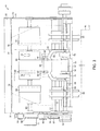
- Figs. 1 to 4 show the banknote storing and feeding unit 19.
- the banknote storing and feeding unit 19 includes a frame 33 having both side plates 31 and a connection member 32 for connecting these side plates 31.
- a banknote depositing and dispensing port 35 as a paper sheet depositing and dispensing port facing the transport path 17; first and second winding reels 38 and 39 to which one end sides of a first tape 36 and a second tape 37 are attached for winding; a winding drum 40 to which the respective other end sides of the respective tapes 36 and 37 are attached for winding; a first guide roller 41 as a first guide unit and a second guide roller 42 as a second guide unit for guiding the respective tapes 36 and 37 at a position facing the banknote depositing and dispensing port 35 ; first andsecondguide rollers 43 and 44 for guiding the tapes 36 and 37 between the winding reels 38 and 39 and the guide rollers 41 and 42, respectively.
- the banknote depositing and dispensing port 35 can receive and feed a banknote 45 transported from and to the transport path 17.
- both tapes 36 and 37 are wound around the winding drum 40, and thus the banknote 45 received from the banknote depositing and dispensing port 35 is held between both tapes 36 and 37 for winding and storing.
- both tapes 36 and 37 are unwound from the winding drum 40, and thus the banknote 45 is fed to the banknote depositing and dispensing port 35.
- the width of the respective tapes 36 and 37 is set shorter than that in the longitudinal direction of the banknote 45 and approximately one-third of the length in the longitudinal direction of the banknote 45, and formed of, for example, a transparent material. Marks (not shown) are formed at an even interval in the width direction on the one side so that the winding quantity and the unwinding quantity of the respective tapes 36 and 37 can be detected.
- a first winding quantity detection sensor 47 and a second winding quantity detection sensor 48 as a winding quantity detecting unit for detecting the marks on the respective tapes 36 and 37 and further detecting the winding quantity of the respective tapes 36 and 37 which are wound around the winding drum 40 are disposed between the guide rollers 41 and 42 and between the guide rollers 43 and 44, respectively.
- Each of the winding reels 38 and 39 is a flanged reel having a flange on both sides, and attached to the middle portion in the axial direction of respective winding reel axes 50 and 51, rotatably installed between both side plates 31 via respective torque limiters 52 and 53.
- One end of the respective winding reel axes 50 and 51 is attached to one side plate 31 via a one-way clutch (not shown), and the winding reel axes 50 and 51 are allowed, by the one-way clutch, to rotate only in a direction corresponding to a tape winding direction (clockwise in Fig. 1 ) of the respective winding reels 38 and 39 when feeding banknotes, and are prevented from rotating in a direction corresponding to a tape unwinding direction (counterclockwise in Fig. 1 ) of the respective winding reels 38 and 39 when storing banknotes.
- the first guide roller 41 and the second guide roller 42 are flanged rollers each having a flange on both sides, and rotatably attached to a first roller axis 55 and a second roller axis 56, respectively.
- the first roller axis 55 is supported by a bracket 57 attached to the frame 33, and the second roller axis 56 is supportedbetweenboth side plates 31.
- the respective tapes 36 and 37 from the respective winding reels 38 and 39 to the winding drum 40 are placed around the guide rollers 41 and 42 so as to face separately from each other, and an approximately triangular space 58 is formed between placing positions of both tapes 36 and 37.
- the space 58 functions when storing banknotes so that the banknote 45 is received in the space 58 and wound around the winding drum 40 while being held between both tapes 36 and 37.
- the guide rollers 41 and 42 as a guiding unit are not necessarily required to be a roller rotatable with respect to the roller axes 55 and 56, and may be a fixed roller having a small sliding resistance against the tapes 36 and 37 or a fixedmember separatelyprovided.
- the respective guide rollers 43 and 44 are rotatably attached to the center position in the axial direction of the respective guide roller axes 60 and 61 which are installed between both side plates 31.
- the winding drum 40 is attached to a winding drum axis 63 rotatably installed between both side plates 31.
- the winding drum 40 includes: a tape winding drum unit 64 which is located at the center of the winding drum axis 63 and around which both tapes 36 and 37 are wound; and a pair of banknote winding drum units 65 for winding both side regions in the longitudinal direction of the banknote 45, which is wound in the short-side direction by both tapes 36 and 37 on both sides in the axial direction of the tape winding drum 64.
- a pulley 67 (a pulley of the winding reel axis 51 is not shown) having a small diameter is attached to the respective winding reel axes 50 and 51 via a one-way clutch (not shown) outside of one side plate 31, a pulley 68 having a large outer diameter is attached to the winding drum axis 63, further, a driving pulley (not shown) and a plurality of guide pulleys 69 are rotatably provided on the outside of one side plate 31, and an endless driving belt 70 is placed throughout these pulleys 67, 68 and 69. Additionally, amotor 71 for rotating the driving pulley in the forward and reverse direction is attached to the outside of one side plate 31.
- the respective winding reel axes 50 and 51 constantly rotate faster than the winding drum axis 63 due to a difference in diameter between the pulley 67 of the respective winding reel axes 50 and 51 and the pulley 68 of the winding drum axis 63.
- a rotation driving force is transmitted from the pulley 67 to the respective winding reel axes 50 and 51 via the one-way clutch only in a direction corresponding to the tape winding direction (clockwise in Fig. 1 ) of the respective winding reels 38 and 39 when feeding banknotes, and the winding reel axes rotate in the same direction.
- the rotation driving force from the pulley 67 is cut off in a direction corresponding to the tape unwinding direction (counterclockwise in Fig. 1 ) of the respective winding reels 38 and 39 when storing banknotes.
- the respective winding reel axes 50 and 51 are prevented, by the one-way clutch, from rotating in the direction corresponding to the tape unwinding direction of the respective winding reel axes 50 and 51 (counterclockwise in Fig. 1 ).
- a pair of transport rollers 75 are disposed as a transport unit for holding and sending the banknote 45, which is transported from the transport path 17, to a space betweenboth tapes 36 and 37 when storing banknotes , and holding and feeding the banknote 4 5 , which is fed from between both tapes 36 and 37 by unwinding from the winding drum 40, to the transport path 17 when feeding banknotes.
- These transport rollers 75 are attached to the respective roller axes 55 and 56 at both sides of the respective guide rollers 41 and 42, and rotate integrally with the roller axes 55 and 56, respectively.
- first guide levers 77 and 78 are swingably supported for guiding one face of the banknote 45 to be wound and stored around the winding drum 40 or to be unwound and fed at a position of the tape winding drum unit 64 of the winding drum 40 and respective positions of the respective banknote winding drum units 65 of the drum 40.
- These first guide levers 77 and 78 follow movably in accordance with an increase or decrease in banknote 45 to be wound around the winding drum 40.
- a banknote pressing roller 79 for pressing the banknote 45 against the winding drum 40 on both sides of both tapes 36 and 37 is rotatably supported on the center first guide lever 77.
- a support axis 81 is rotatably installed at the side position facing the winding drum 40 between both side plates 31, a base end of a swinging lever 82 is attached to the center of the support axis 81, and a contact roller 83 is rotatably attached to a top end of the swinging lever 82 via a contact roller axis 84, the roller 83 being a contact body coming into contact with an outer circumferential face of a portion around which both tapes 36 and 37 are wound to detect the outer diameter of the winding drum 40 around which the banknote 45 is wound.
- the swinging lever 82 is biased by a biasing unit such as a spring so that the contact roller 83 constantly comes into contact with the outer circumferential face of the winding drum 40.
- the support axis 81 is arranged at a position so as not to interfere with the outer diameter of the winding drum 40 even when the outer diameter of the winding drum 40 becomes maximum when the maximum quantity of the banknotes 45 are wound around the winding drum 40.
- An outer diameter detecting unit 85 is constituted for detecting the outer diameter of the winding drum 40 around which the banknote 45 is wound by the swinging lever 82, the contact roller 83, and the biasing unit, etc., that is, for detecting the outer diameter of the portion of the winding drum 40 for winding both tapes 36 and 37 from the state where no banknote 45 is wound to the state where a maximum quantity of the banknotes 45 are wound.
- the contact roller 83 as a contact body is not required to be a roller, and may be a fixed member having a small sliding resistance against the first tape 36.
- the portion of the winding drum 40 winding the banknote 45 the outer diameter of which is detected by the outer diameter detecting unit 85 is not limited to a portion which winds both tapes 36 and 37, and may be a portion which winds the end portion side in the longitudinal direction of the banknote 45 projecting from both tapes 36 and 37. In this case, although the detection accuracy lowers, change in the outer diameter of the winding drum 40 can be detected in accordance with the winding quantity of the banknote 45 wound around the winding drum 40.
- a tape pressing body 87 is swingably supported by the second roller axis 56, which is located between the respective winding reels 38 and 39 and the winding drum 40, and presses the first tape 36 from the second tape 37 side so as to bring both tapes 36 and 37 into contact with each other between the respective guide rollers 41,42 and the transport rollers 75, and the winding drum 40.
- the tape pressing body 87 is formed in an approximate U-shape and includes a swinging member 88 having both ends rotatably supported by the first roller axis 55, and, on a top end of the swinging member 88, a tape pressing roller 89 which comes into contact with and presses the second tape 37 is rotatably supported by a tape pressing roller axis 90.
- the tape pressing roller 89 is formed so as to have the same width as that of both tapes 36 and 37. Moreover, the tape pressing roller 89 as a tape pressing body 87 is not required to be a roller, and may be a fixed member having a small sliding resistance against the tapes 36 and 37.
- a moving unit 92 is provided for moving the tape pressing body 87 in accordance with the outer diameter of the winding drum 40.
- the moving unit 92 is constituted by an interlocking mechanism 94 in which the contact roller axis 84 of the contact roller 83 and the tape pressing roller axis 90 of the tape pressing roller 89 are linked with each other via a link 93, and makes the tape pressing body 87 move in conjunction with movement of the contact roller 83 in accordance with the outer diameter of the winding drum 40.
- a second guide lever 96 for guiding both side regions in the longitudinal direction of the other face of a banknote are attached corresponding to respective positions of the banknote winding drum units 65 at both sides of the winding drum.
- the second guide lever 96 is fixed to the support axis 81 so as to swing integrally with the swinging lever 82.
- a banknote detection sensor 98 for detecting the banknote 45 passing for storage or feeding is disposed between the winding drum 40 and both guide rollers 41 and 42.
- the motor 71 is rotation-driven in a direction corresponding to the banknote storing direction by detecting the banknote 45 by a sensor provided on the transport path 17.
- the winding drum 40 is rotated in the tape winding direction via the driving belt 70 and the pulley 68 to start winding both tapes 36 and 37 around the winding drum 40.
- the respective pulleys 67 also rotate via the driving belt 70, the rotation driving force is not transmitted to the respective winding reel axes 50 and 51 by the one-way clutch, and the respective winding reel axes 50 and 51 do not rotate in a direction corresponding to the tape unwinding direction from the respective winding reels 38 and 39. Since the winding reel axes 50 and 51 are prevented from rotating in the direction corresponding to the tape unwinding direction from the respective winding reels 38 and 39 by the one-way clutch, the winding reels 38 and 39 attached to the respective winding reel axes 50 and 51 via the torque limiters 52 and 53 do not rotate in the unwinding direction, and tension is applied to the respective tapes 36 and 37 to be wound around the winding drum 40.
- a center region in the longitudinal direction of the banknote 45 is held between the pair of transport rollers 75.
- the pair of transport rollers 75 rotate integrally with the respective guide rollers 41 and 42 rotating with movement of the respective tapes 36 and 37, and send the held banknote 45 to the space between both tapes 36 and 37.
- the banknote 45 sent to the space between the both tapes 36 and 37 is held between both tapes 36 and 37 at a position of the tape pressing roller 89 pressing both tapes 36 and 37 so as to bring them into contact with each other, and then wound around the tape winding drum unit 64 of the winding drum 40 together with both tapes 36 and 37 for storing.
- both tapes 36 and 37 wound around the winding drum 40 are pressed by the contact roller 83 to apply a fastening force to both tapes 36 and 37.
- the banknote 45 can be wound and stored at an appropriate fastening force, and a rate of increase in the outer diameter of the winding drum 40 with an increase in the storage quantity of the banknotes 45 can be reduced.
- the motor 71 Based on detection of passage of the banknote 45, which is to be wound and stored around the winding drum 40, by a banknote detection sensor 98 and detection of the winding quantity of the respective tapes 36 and 37 by the respective winding quantity detection sensors 47 and 48, the motor 71 is stopped at a predetermined timing that the banknote 45 is wound around the winding drum 40, winding of both tapes 36 and 37 around the winding drum 40 is stopped, and one banknote 45 is completely stored.
- Such storing operation is repeated at a predetermined number of times when storing a predetermined number of banknotes 45.
- Fig. 4(a) shows a change in the outer diameter of the portion of the winding drum 40 winding the tape in the state where no banknote 45 is stored
- Fig. 4(b) shows the change described above in the state where 100 banknotes 45 are stored
- Fig. 4 (c) shows the change described above in the state where 200 banknotes 45 are stored
- Fig. 4 (d) shows the change described above in the state where 300 banknotes 45 are stored
- Fig. 4(e) shows the change described above in the state where 400 banknotes 45 are stored.
- a distance a1 between a tape winding position of the winding drum 40 and a tape contact position of the tape pressing roller 89 and a distance b1 between the tape contact position of the tape pressing roller 89 and a holding position of the pair of transport rollers 75 are shorter than the length in the transporting direction of the banknote 45, respectively (the length in its short-side direction of the banknote 45).
- a top end in the transporting direction of the banknote 45 reaches the tape contact position of the tape pressing roller 89 and the banknote 45 is heldbetween both tapes 36 and 37 with the banknote 45 held between the pair of transport rollers 75, and the top end in the transporting direction of the banknote 45 reaches the tape winding position of the winding drum 40 with the banknote 45 held between both tapes 36 and 37 at the tape contact position of the tape pressing roller 89, and then the banknote 45 is wound and stored, thereby the banknote 45 sent from the transport path 17 can be transported while being constantly held, and can be stably wound and stored around the winding drum 40.
- the swinging lever 82 follows and swings in the direction away from the center of the winding drum 40 via the contact roller 83, and the swinging member 88 also follows and swings in the direction away from the center of the winding drum 40 via the link 93.
- the distance a1 between the tape winding position of the winding drum 40 and the tape contact position of the tape pressing roller 89 changes to distances a2, a3, a4 and a5 in this order by swinging of the swinging member 88, all of the distances a1 to a5 are shorter than the length in the transporting direction of the banknote 45 (the length in its short-side direction of the banknote 45).
- the distance b1 between the tape contact position of the tape pressing roller 89 and the holding position of the pair of transport rollers 75 changes to distances b2, b3, b4 and b5 in this order, all of the distances b1 to b5 are shorter than the length in the transporting direction of the banknote 45 (the length in its short-side direction of the banknote 45) .
- the banknote 45 sent from the transport path 17 can be transported while being constantly held, and can be stably wound and stored around the winding drum 40.
- the tape pressing roller 89 is added to the swinging member 88 so as to press at two appropriate positions and a part longer than the length in the transporting direction of the banknote 45 is canceled, thereby the banknote 45 can be transported while being constantly held.
- the motor 71 is rotation-driven in a direction corresponding to a banknote feeding direction.
- the winding drum 40 rotates in a tape unwinding direction via the driving belt 70 and the pulley 68 to start unwinding both tapes 36 and 37 from the winding drum 40.
- the respective winding reel axes 50 and 51 rotate in a direction corresponding to the tape winding direction by the winding reels 38 and 39 via the driving belt 70, the respective pulleys 67 and the one-way clutch.
- the one-way clutch permits the respective winding reel axes 50 and 51 to rotate in the direction corresponding to the tape winding direction by the respective winding reels 38 and 39.
- the respective winding reels 38 and 39 rotate in the tape winding direction via the torque limiters 52 and 53 by rotation of the respective winding reel axes 50 and 51 to wind the respective tapes 36 and 37 around the winding reels 38 and 39.
- the respective winding reels 38 and 39 of the respective winding reel axes 50 and 51 rotate faster than the winding drum 40 of the winding drum axis 63.
- the tape winding speed of the respective winding reels 38 and 39 becomes higher than the tape unwinding speed from the winding drum 40, and tension is applied to the respective tapes 36 and 37 to be wound around the respective winding reels 38 and 39.
- the banknote 45 By unwinding both tapes 36 and 37 from the winding drum 40, the banknote 45 is unwound together with both tapes 36 and 37.
- the banknote 45 unwound from the winding drum 40 passes the tape pressing roller 89 pressing both tapes 36 and 37 to bring the tapes into contact with each other, and then is held between the pair of transport rollers 75 and fed to the transport path 17 through the banknote depositing and dispensing port 35 from a space between the pair of transport rollers 75.
- both side regions in the longitudinal direction of the banknote 45 fed from the winding drum 40 to the banknote depositing and dispensing port 35 are guided by the first guide levers 77 and 78 and the second guide lever 96, thereby it is difficult to catch both ends in the longitudinal direction of the banknote 45 and the banknote 45 can be smoothly fed.
- the motor 71 When a plurality of banknotes 45 are fed, the motor 71 is continuously driven even after passage of the fed banknote 45 is detected by the banknote detection sensor 98, the motor 71 is stopped at a predetermined timing after passage of a predetermined number of fed banknotes 45 is detected by the banknote detection sensor 98, and the plurality of banknotes 45 are completely fed.
- the swinging lever 82 follows and swings in a direction approaching the center of the winding drum 40 via the contact roller 83, and the swinging member 88 also follows and swings in the direction approaching the center of the winding drum 40 via the link 93.
- the distance between the tape winding position of the winding drum 40 and the tape contact position of the tape pressing roller 89 changes to the distances a5, a4, a3, a2 and a1 in this order by swinging of the swinging member 88, all the distances a5 to a1 are shorter than the length in the transporting direction of the banknote 45 (the length in its short-side direction of the banknote 45).
- the distance between the tape contact position of the tape pressing roller 89 and the holding position of the pair of transport rollers 75 changes to the distances b5, b4, b3, b2 and b1 in this order, all the distances b5 to b1 are shorter than the length in the transporting direction of the banknote 45 (the length in its short-side direction of the banknote 45) .
- the fed banknote 45 can be transported while being constantly held, and can be stably fed to the transport path 17.
- the first tape 36 and the second tape 37 are thus pressed by the tape pressing body 87, so as to come into contact with each other, between the first and second winding reels 38 and 39 and the winding drum 40, thereby even a banknote 45 having a short length in the transporting direction can be held between the first tape 36 and the second tape 37 at a position of the tape pressing body 87, and reliably transported.
- the outer diameter of the winding drum 40 is detected by the contact roller 83 following and moving in accordance with the outer diameter of the winding drum 40 and the tape pressing body 87 is moved via the link 93 of the interlocking mechanism 94 in accordance with the detected outer diameter of the winding drum 40, thereby the tape pressing body 87 can be moved to an appropriate position following a change in the outer diameter of the winding drum 40, and thus the maximum storage quantity of the banknote 45 can be increased and the banknote 45 can be stably stored and fed.
- both tapes 36 and 37 can be prevented from largely folding at the position of the tape pressing body 87, so that trouble can be prevented from occurring in the storage state of the banknote 45 when the banknote 45 is wound and stored around the winding drum 40.
- Figs. 6 and 7 show a second embodiment.
- the outer diameter detecting unit 85 includes: the support axis 81, the swinging lever 82, the contact roller 83, the contact roller axis 84 and a contact body movement amount detecting unit 101 for detecting the movement amount of the contact roller 83 following and moving in accordance with the outer diameter of the portion of the winding drum 40 around which both tapes 36 and 37 are wound.
- a potentiometer, rotary encoder or the like for detecting the movement amount of the contact roller 83 based on the rotation amount of the swinging lever 82 around the support axis 81 is used for the contact body movement amount detecting unit 101.
- the swinging lever 82 here rotationally moves, a supporting system for making the contact roller 83 linearly move may be adopted. In this case, a sensor for detecting the linear movement amount is used.
- the interlocking mechanism 94 used in the first embodiment is not used, but a driving unit 102 for moving the tape pressing body 87 in accordance with the movement amount of the contact roller 83 detected by the contact body movement amount detecting unit 101 is used.
- a driving unit 102 for moving the tape pressing body 87 in accordance with the movement amount of the contact roller 83 detected by the contact body movement amount detecting unit 101 is used.
- a steppingmotor the rotation position of which canbe controlled is used for the driving unit 102, and drives the second roller axis 56.
- the pair of transport rollers 75 can be rotated with respect to the second roller axis 56, so that the upper and lower transport rollers 75 integrally rotate being driven by the roller axis 55.
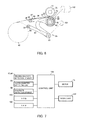
- Fig. 7 shows a control unit 104 for controlling the banknote storing and feeding unit 19.
- the control unit 104 enters detection signals from the winding quantity detection sensors 47 and 48 , the outer diameter detectingunit 85 having the contact bodymovement amount detecting unit 101, the banknote detection sensor 98, etc., to control the motor 71 and the driving unit 102, etc.
- the control unit 104 can communicate with a higher-ranking control unit included in the banknote processing machine 11, or the control unit 104 itself is constituted by the control unit of the banknote processing machine 11.
- the control unit 104 includes a ROM 105 and RAM 106 for storing programs, various data, etc.
- the control unit 104 stores a table defining the outer diameter value of the winding drum 40 corresponding to the movement amount of the contact roller 83 or a relational expression between the movement amount of the contact roller 83 and the outer diameter value of the winding drum 40. Further, the control unit 104 stores a table defining a position of the tape pressing body 87 according to the outer diameter value of the winding drum 40 or a relational expression.
- control unit 104 can determine the outer diameter of the winding drum 40 in accordance with the movement amount of the contact roller 83 detected by the contact body movement amount detecting unit 101, controls the driving unit 102 in accordance with the movement amount of the contact roller 83 detected by the contact body movement amount detecting unit 101, and as shown in Fig. 4 , swings the tape pressing body 87 in the direction away from the center of the winding drum 40 when the outer diameter of the winding drum 40 is large, and swings the tape pressing body 87 in the direction approaching the center of the winding drum 40 when the outer diameter of the winding drum 40 is small.
- the movement amount of the contact roller 83 following and moving in accordance with the outer diameter of the winding drum 40 is detected by the contact body movement amount detecting unit 101, and the tape pressing body 87 can be moved to an appropriate position by the driving unit 102.
- Fig. 8 shows a third embodiment.
- a non-contact detection sensor 108 which detects, without contact, the outer diameter of the portion of the winding drum 40 around which both tapes 36 and 37 are wound.
- the non-contact detection sensor 108 for example, irradiates an LED light to the portion of the winding drum 40 around which both tapes 36 and 37 are wound, measures light reflected from there by use of a photodiode to measure a distance between the non-contact detection sensor 108 and the portion of the winding drum 40 around which both tapes 36 and 37 are wound.
- control unit 104 shown in Fig. 7 is used.
- the control unit 104 can determine the outer diameter of the winding drum 40 based on the distance between the non-contact detection sensor 108 and the winding drum 40 detected by the non-contact detection sensor 108, controls the driving unit 102 in accordance with the outer diameter of the winding drum 40 detected by the non-contact detection sensor 108, and similar to that shown in Fig. 4 , swings the tape pressing body 87 in the direction away from the center of the winding drum 40 when the outer diameter of the winding drum 40 is large, and swings the tape pressing body 87in the direction approaching the center of the winding drum 40 when the outer diameter of the winding drum 40 is small.
- the outer diameter of the winding drum 40 is thus detected by the non-contact detection sensor 108, thereby the tape pressing body 87 can be moved to an appropriate position by the driving unit 102.
- the outer diameter detecting unit 85 may be constituted so that the winding quantity of both tapes 36 and 37 wound around the winding drum 40 is detected by both winding quantity detection sensors 47 and 48 to estimate the outer diameter of the portion of the winding drum 40 around which both tapes 36 and 37 are wound based on the winding quantity of both tapes 36 and 37 wound around the winding drum 40.
- the driving unit 102 is controlled, and similar to that shown in Fig.
- the tape pressing body 87 is swung in the direction away from the center of the winding drum 40 when the outer diameter of the winding drum 40 is large, and swung in the direction approaching the center of the winding drum 40 when the outer diameter of the winding drum 40 is small.
- the control unit 104 estimates the outer diameter of the winding drum 40 by use of a table of outer diameter estimation values corresponding to the winding quantity, an approximation expression of a relationship between the winding quantity and the outer diameter estimation value, or the like.
- the outer diameter detecting unit 85 may be constituted so that the banknote 45 stored or fed is detected by the banknote detection sensor 98 or the transport path 17, thereby the storage number of banknotes 45 wound and stored around the winding drum 40 is counted to estimate the outer diameter of the portion of the winding drum 40 around which both tapes 35 and 37 are wound.
- the outer diameter of the winding drum 40 is estimated to control the driving unit 102 by counting the storage number of banknotes 45 wound and stored around the winding drum 40, and similar to that shown in Fig.
- the tape pressing body 87 is swung in the direction away from the center of the winding drum 4 0 when the outer diameter of the winding drum 40 is large, and swung in the direction approaching the center of the winding drum 40 when the outer diameter of the winding drum 40 is small.
- the control unit 104 estimates the outer diameter of the winding drum 40 by use of a table of outer diameter estimation values corresponding to the storage numbers, an approximation expression of a relationship between the storage number and the outer diameter estimation value, or the like.
- the outer diameter detecting unit 85 may be constituted so that the rotation amount of at least either the winding drum 40 and the winding reels 38 and 39 are detected by the rotation amount detecting unit to estimate the outer diameter of the portion of the winding drum 40 around which both tapes 36 and 37 are wound based on the winding quantity of both tapes 36 and 37 wound around the winding drum 40.
- the outer diameter of the winding drum 40 is estimated to control the driving unit 102, similar to that shown in Fig.
- the tape pressing body 87 is swung in the direction away from the center of the winding drum 40 when the outer diameter of the winding drum 40 is large, and swung in the direction approaching the center of the winding drum 40 when the outer diameter of the winding drum 40 is small.
- the control unit 104 estimates the outer diameter of the winding drum 40 with use of a table of outer diameter estimation values corresponding to the rotation amounts, an approximation expression of a relationship between the rotation amounts and the outer diameter estimation values, or the like.
- a pair of tape pressing rollers may be used which may press from the first tape 36 side and hold both tapes 36 and 37 so as to reliably bring both tapes 36 and 37 into contact with each other.
- the pair of transport rollers 75 may be provided not only at the positions of the guide rollers 41 and 42 but also at the banknote depositing and dispensing port 35 side or transport path 17 side, and may serve as a transport roller of the transport path 17.
- first and second guide rollers 41 and 42 are used as first and second guide units for guiding the first and second tapes 36 and 37 between the first and second winding reels 38 and 39 and the winding drum 40 so that the banknote 45 is transported to the space between both tapes 36 and 37
- the guide rollers 41 and 42 may be omitted.
- the tape pressing roller 89 can be made to serve as a guide roller by, for example, arranging the respective winding reels 38 and 39 in the vicinity of the banknote depositing and dispensing port 35 and directly placing the respective tapes 36 and 37 between the respective winding reels 38 and 39 and the winding reel 40 around the tape pressing roller 89.
- a guide member for guiding the banknote 45, which is to be transported to the space between both tapes 36 and 37 and the banknote 45 which is to be fed from between both tapes 36 and 37, between the tape pressing roller 89 and the transport rollers 75 may be provided so as to respond to a change in the outer diameter of the portion of the respective winding reels 38 and 39 around which the respective tapes 36 and 37 are wound. Additionally, only one of the guide rollers 41 and 42 can be omitted.
- the present invention is adopted for an escrow unit for escrowing banknotes, a banknote storing unit for storing and feeding banknotes, etc., in a banknote processing unit, and further for a paper sheet processing unit for handling paper sheets such as checks, vouchers and sheets.
Abstract
Description
- The present invention relates to a paper sheet storing and feeding unit which stores and feeds paper sheets by winding and unwinding tapes.
- In a banknote processing machine such as a banknote depositing and dispensing machine for depositing and dispensing banknotes as paper sheets, for example, a tape storage type banknote storing and feeding unit using two tapes for storing and feeding banknotes has been conventionally used.
- In the banknote storing and feeding unit, two tapes are used, one end side of the respective tapes is attached to two winding reels and wound around the reels, the other end side of the respective tapes, facing each other, is attached to one winding drum and wound around the drum. The respective tapes between the two winding reels and the winding drum are guided to the banknote depositing and dispensing position where transported banknotes are received or banknotes are deposited or dispensed by the guide rollers. Additionally, at a position coaxial to each of the guide rollers, a pair of transport rollers are disposed holding a banknote transported to the banknote depositing and dispensing position to send it to a space between the pair of tapes which are to be wound around the winding drum, and holding the banknote fed from between the pair of tapes, which are unwound from the winding drum to feed it from the banknote depositing and dispensing position.
- When storing banknotes, a transported banknote is held between the transport rollers to send it to the space between the two tapes, the transported banknote by the transport rollers is wound and stored around the winding drum being held between the two tapes by winding the two tapes around the winding drum. When feeding banknotes, the two tapes are unwound from the winding drum, thereby feeding the banknote fed from between the two tapes being held by the transport rollers (see, for example, Patent Document 1).
- Additionally, there is a banknote storing and feeding unit in which two tapes are largely folded into one by a pressing roller, which is provided in the vicinity of a winding drum, between the winding drum and guide rollers, and a banknote is held between the two tapes (see, for example, Patent Document 2) .
- Additionally, there is a banknote storing and feeding unit in which only one tape is used, and, by winding the tape around a winding drum, banknotes are sent into a space between an outer circumferential face of the winding drum and the tape which is to be wound around the winding drum for winding and storing. On the other hand, by unwinding the tape from the winding drum, banknotes are peeled off from the winding drum by a scraper coming into contact with the outer circumferential face of the winding drum for feeding. The scraper is provided swingably in accordance with an outer diameter of the winding drum around which the tape is wound, and a top end of the scraper is biased by a spring so as to constantly come into contact with the winding drum, and an auxiliary roller for holding a banknote between the scraper and the tape is provided integrally with a middle portion of the scraper (see, for example, Patent Document 3).
- In such a banknote storing and feeding unit, the distance between a tape winding position of the winding drum and the transport rollers changes in accordance with the maximum storage quantity of banknotes. As the maximum storage quantity of banknotes increases, the outer diameter of the winding drum becomes large and the distance between the tape winding position of the winding drum and the transport rollers becomes long.
- Thus, in the case of increasing the maximum storage quantity of banknotes more than conventionally, the distance between the tape winding position of the winding drum and the transport rollers becomes longer than the length in a transporting direction of a banknote. Thus, even if a banknote having a length in the transporting direction shorter than the distance between the tape winding position of the winding drum and the transport rollers is located between the two tapes, it is not held between the tape winding position of the winding drum and the transport rollers. Therefore, it is impossible to stably store and feed banknotes. That is, it is difficult for the conventional banknote storing and feeding unit to increase the maximum storage quantity of banknotes.
- Additionally, there is a banknote storing and feeding unit in which two tapes are largely folded into one by a pressing roller provided in the vicinity of a winding drum between the winding drum and guide rollers to hold a banknote therebetween. However, since the pressing roller is fixed, the outer diameter of the winding drum is regulated, and it is difficult to increase the maximum storage quantity of banknotes. Further, since the tapes are largely folded by the pressing roller, a banknote is folded reversely to the winding direction of the winding drum and there is a possibility of causing trouble with the storage state of banknotes wound and stored around the winding drum, in the case of using tapes each having a width shorter than that of the banknote.
- Additionally, there is a banknote storing and feeding unit using only one tape, in which a banknote is held between an auxiliary roller provided integrally with the middle portion of a scraper swingable in accordance with the outer diameter of the winding drum, the outer diameter of the winding drum capable of making both the scraper and auxiliary roller function has an appropriate range, and in the case where the outer diameter exceeds the appropriate range, the scraper and the auxiliary roller do not function, therefore, the outer diameter of the winding drum is regulated, thereby it is difficult to increase the maximum storage quantity of banknotes.
- Patent Document 1: Japanese Laid-open Patent Publication No.
2006-69708 Figs. 1 and2 ) - Patent Document2: Japanese Laid-open Patent Publication No.
3-128854 Fig. 1 ) - Patent Document 3 : Japanese Laid-open Patent Publication No.
2000-123219 Figs. 1 and2 ) - The present invention aims to provide a paper sheet storing and feeding unit for storing and feeding paper sheets by winding and unwinding tapes, wherein the maximum storage quantity of paper sheets can be increased and paper sheets can be stably stored and fed.
- A paper sheet storing and feeding unit according to claim 1 of the invention is a paper sheet storing and feeding unit for storing transported paper sheets and feeding stored paper sheets outward, and includes: a first tape; a second tape; a first winding reel to which one end of the first tape is attached and around which the first tape is wound and unwound; a second winding reel to which one end of the second tape is attached and around which the second tape is wound and unwound; a winding drum, to which other ends of the first and second tapes are attached so that at least a part of the first tape and a part of the second tape are overlapped when the first and second tapes are wound, and around which the first and second tapes and a paper sheet held between the first and second tapes are wound and unwound; a tape pressing bodywhich is arranged between the first and second winding reels and the winding drum and presses the first and second tapes at least one place so as to bring the first and second tapes into contact with each other; an outer diameter detectingunit for detecting the outer diameter of the winding drum around which the paper sheet is wound; and a moving unit for moving the tape pressing body in accordance with the outer diameter of the winding drum detected by the outer diameter detecting unit.
- The first tape and second tape are pressed by the tape pressing body so as to come into contact with each other between the first and second winding reels and the winding drum, thereby even a banknote having a small length in a transporting direction can be held between the first tape and second tape at a position of the tape pressing body and reliably transported. Additionally, the outer diameter of the winding drum is detected by the outer diameter detecting unit and the tape pressing body is moved by the moving unit in accordance with the detected outer diameter of the winding drum, thereby the tape pressing body can be moved to an appropriate position following a change in the outer diameter of the winding drum. Thus, the maximum storage quantity of paper sheets can be increased, and paper sheets can be stably stored and fed. Additionally, the tape pressing body is moved in accordance with the outer diameter of the winding drum, thereby the first and second tapes can be prevented from largely folding at the position of the tape pressing body, and troubles can be prevented from occurring in the storage state of banknotes wound and stored around the winding drum.
- With a paper sheet storing and feeding unit according to claim 2 of the invention, in the paper sheet storing and feeding unit according to claim 1, at least one of the following guide units is included: a first guide unit which is pressed against the first tape between the tape pressing body and the first winding reel to guide the first tape so that the paper sheet is transported to a space between the first tape and the second tape; and a second guide unit which is pressed against the second tape between the tape pressing body and the second winding reel to guide the second tape so that the paper sheet is transported to the space between the first tape and the second tape.
- The first and second tapes are guided by the first and second guide units and a paper sheet can be transported to the space between the first tape and the second tape, positions of the winding reels can be freely determined and compact design can be realized in accordance with conditions of set-up palaces.
- With a paper sheet storing and feeding unit according to claim 3 of the invention, in the paper sheet storing and feeding unit according to claim 1, the outer diameter detecting unit includes a contact body which comes into contact with an outer circumferential face of the winding drum around which the paper sheet is wound and follows and moves in accordance with the outer diameter of the winding drum, and the moving unit includes an interlocking mechanism which moves the tape pressing body in accordance with movement of the contact body.
- The tape pressing body is interlocked with the contact body, which follows and moves in accordance with the outer diameter of the winding drum via the interlocking mechanism, thereby the tape pressing body can be moved to an appropriate position by a simple constitution.
- With a paper sheet storing and feeding unit according to claim 4 of the invention, in the paper sheet storing and feeding unit according to claim 1, the moving unit includes a driving unit for moving the tape pressing body in accordance with the outer diameter of the winding drum detected by the outer diameter detecting unit.
- The tape pressing body can be moved to an appropriate position by the driving unit.
- With a paper sheet storing and feeding unit according to claim 5 of the invention, in the paper sheet storing and feeding unit according to claim 1, the outer diameter detecting unit includes: a contact body which comes into contact with the outer circumferential face of the winding drum around which the paper sheet is wound and follows and moves in accordance with the outer diameter of the winding drum; and a contact body movement amount detecting unit for detecting a movement amount of the contact body, and the moving unit includes a driving unit for moving the tape pressing body in accordance with the movement amount of the contact body detected by the contact body movement amount detecting unit.
- The movement amount of the contact body following and moving in accordance with the outer diameter of the winding drum is detected, thereby the tape pressing body can be moved to an appropriate position by the driving unit.
- With a paper sheet storing and feeding unit according to claim 6 of the invention, in the paper sheet storing and feeding unit according to claim 1, the outer diameter detecting unit includes a non-contact detection sensor for detecting, without contact, the outer diameter of the winding drum around which the paper sheet is wound, and the moving unit includes a driving unit for moving the tape pressing body in accordance with the outer diameter of the winding drum detected by the non-contact detection sensor.
- The outer diameter of the winding drum is detected by the non-contact detection sensor, thereby the tape pressing body can be moved to an appropriate position by the driving unit.
- With a paper sheet storing and feeding unit according to claim 7 of the invention, in the paper sheet storing and feeding unit according to claim 1, the outer diameter detecting unit detects the winding quantity of the first and second tapes which are wound around the winding drum, and the moving unit includes a driving unit for moving the tape pressing body in accordance with the winding quantity of the first and second tapes which are wound around the winding drum detected by the outer diameter detecting unit.
- The winding quantity of the first and second tapes which are wound around the winding drum is detected, thereby the outer diameter of the winding drum can be estimated and the tape pressing body can be moved to an appropriate position by the driving unit.
- With a paper sheet storing and feeding unit according to
claim 8 of the invention, in the paper sheet storing and feeding unit according to claim 1, the outer diameter detecting unit counts the number of paper sheets wound and stored around the winding drum, and the moving unit includes a driving unit for moving the tape pressing body in accordance with the storage number of paper sheets counted by the outer diameter detecting unit. - The paper sheets wound and stored around the winding drum are counted, thereby the outer diameter of the winding drum around which paper sheets are wound can be estimated and the tape pressing body can be moved to an appropriate position by the driving unit.
- With a paper sheet storing and feeding unit according to claim 9 of the invention, in the paper sheet storing and feeding unit according to claim 1, the outer diameter detecting unit detects the rotation amount of at least either the winding drum or the winding reel, and the moving unit includes a driving unit for moving the tape pressing body in accordance with the rotation amount of at least either the winding drum or the winding reel detected by the outer diameter detecting unit.
- The rotation amount of at least either the winding drum or the winding reel is detected, thereby the outer diameter of the winding drum around which paper sheets are wound can be estimated and the tape pressing body can be moved to an appropriate position by the driving unit.
- According to a paper sheet storing and feeding unit of the present invention, the maximum storage quantity of paper sheets can be increased and paper sheets can be stably stored and fed.
-
-
Fig. 1 is a cross sectional view of a paper sheet storing and feeding unit of a first embodiment of the present invention,Fig. 1(a) is a cross sectional view of the unit in which no paper sheets are stored, andFig. 1(b) is a cross sectional view of the unit in which a maximum storage quantity of paper sheets are stored. -
Fig. 2 is a perspective view showing the paper sheet storing and feeding unit a part of which is omitted. -
Fig. 3 is a plan view showing the paper sheet storing and feeding unit a part of which is omitted. -
Fig. 4 shows operation of the paper sheet storing and feeding unit in accordance with the storage quantity of paper sheets,Fig. 4 (a) is an explanatory view of the unit in which no paper sheets are stored,Fig. 4(b) is an explanatory view of the unit in which 100 paper sheets are stored,Fig. 4(c) is an explanatory view of the unit in which 200 paper sheets are stored,Fig. 4(d) is an explanatory view of the unit in which 300 paper sheets are stored, andFig. 4(e) is an explanatory view of the unit in which 400 paper sheets are stored. -
Fig. 5 is an explanatory view of a paper sheet processing machine using the paper sheet storing and feeding unit. -
Fig. 6 is an explanatory view of a paper sheet storing and feeding unit of a second embodiment of the present invention. -
Fig. 7 is a block diagram of the paper sheet storing and feeding unit. -
Fig. 8 is an explanatory view of a paper sheet storing and feeding unit of a third embodiment of the present invention. -
- 19
- Banknote storing and feeding unit as paper sheet storing and feeding unit
- 36
- First tape
- 37
- Second tape
- 38
- First winding reel
- 39
- Second winding reel
- 40
- Winding drum
- 41
- First guide roller as first guide unit
- 42
- Second guide roller as second guide unit
- 45
- Banknote as paper sheet
- 83
- Contact roller as contact body
- 85
- Outer diameter detecting unit
- 87
- Tape pressing body
- 92
- Moving unit
- 94
- Interlocking mechanism
- 101
- Contact body movement amount detecting unit
- 102
- Driving unit
- 108
- Non-contact detection sensor
- Hereinafter, embodiments of the present invention will be described with reference to the drawings.
-
Figs. 1 to 5 show a first embodiment. -
Fig. 5 shows a banknote processing machine as a paper sheet processing machine. Abanknote processing machine 11 is a banknote depositing and dispensing machine for depositing and dispensing banknotes as paper sheets, and anupper block 13 and alower block 14 capable of being drawn out from amachine body 12 are provided in themachine body 12. - In the
upper block 13, there are disposed: aninlet 15 fordepositingbanknotes; anoutlet 16 for dispensing banknotes; atransport path 17 for transporting banknotes; arecognition unit 18 for recognizing banknotes transported on thetransport path 17; and a banknote storing and feedingunit 19 as a paper sheet storing and feeding unit which is an escrow unit for escrowing banknotes one by one in the separated state. - In the
lower block 14,stackers 20 for storing banknotes for each denomination which are juxtaposed back and forth; and acassette 21 for storing banknotes is arranged in front of thestackers 20. - A transporting direction of banknotes to be handled by the
banknote processing machine 11 is a short-side direction orthogonal to a longitudinal direction of a banknote. - In a depositing process, banknotes put in the
inlet 15 are sent one by one to thetransport path 17, and recognized by therecognition unit 18. Banknotes recognized as normal by therecognition unit 18 are transported to the banknote storing and feedingunit 19 for escrowing. Additionally, when a storing instruction is issued after a process until escrow of banknotes put in theinlet 15 is completed, the banknotes escrowed in the banknote storing and feedingunit 19 are fed one by one to thetransport path 17, recognized by therecognition unit 18, and then transported to the corresponding denomination-specific stackers 20 for storing. When a returning instruction is issued, the banknotes escrowed in the banknote storing and feedingunit 19 are fed one by one to thetransport path 17, and transported to theoutlet 16 for returning. On the other hand, in a dispensing process, banknotes stored in thestackers 20 of the corresponding dispensing denominations are fed one by one to thetransport path 17 and recognized by therecognition unit 18, and banknotes recognized as normal are transported to theoutlet 16 for dispensing. - Next,
Figs. 1 to 4 show the banknote storing and feedingunit 19. The banknote storing and feedingunit 19 includes aframe 33 having bothside plates 31 and aconnection member 32 for connecting theseside plates 31. - Between both
side plates 31 of theframe 33, there are disposed: a banknote depositing and dispensingport 35 as a paper sheet depositing and dispensing port facing thetransport path 17; first and second windingreels first tape 36 and asecond tape 37 are attached for winding; a windingdrum 40 to which the respective other end sides of therespective tapes first guide roller 41 as a first guide unit and asecond guide roller 42 as a second guide unit for guiding therespective tapes port 35 ;first andsecondguide rollers tapes reels guide rollers - The banknote depositing and dispensing
port 35 can receive and feed abanknote 45 transported from and to thetransport path 17. When storing thebanknote 45, bothtapes drum 40, and thus thebanknote 45 received from the banknote depositing and dispensingport 35 is held between bothtapes banknote 45, bothtapes drum 40, and thus thebanknote 45 is fed to the banknote depositing and dispensingport 35. - The width of the
respective tapes banknote 45 and approximately one-third of the length in the longitudinal direction of thebanknote 45, and formed of, for example, a transparent material. Marks (not shown) are formed at an even interval in the width direction on the one side so that the winding quantity and the unwinding quantity of therespective tapes quantity detection sensor 47 and a second windingquantity detection sensor 48 as a winding quantity detecting unit for detecting the marks on therespective tapes respective tapes drum 40 are disposed between theguide rollers guide rollers - Each of the winding
reels side plates 31 viarespective torque limiters side plate 31 via a one-way clutch (not shown), and the winding reel axes 50 and 51 are allowed, by the one-way clutch, to rotate only in a direction corresponding to a tape winding direction (clockwise inFig. 1 ) of the respective windingreels Fig. 1 ) of the respective windingreels - The
first guide roller 41 and thesecond guide roller 42 are flanged rollers each having a flange on both sides, and rotatably attached to afirst roller axis 55 and asecond roller axis 56, respectively. Thefirst roller axis 55 is supported by abracket 57 attached to theframe 33, and thesecond roller axis 56 issupportedbetweenboth side plates 31. Therespective tapes reels drum 40 are placed around theguide rollers triangular space 58 is formed between placing positions of bothtapes space 58 functions when storing banknotes so that thebanknote 45 is received in thespace 58 and wound around the windingdrum 40 while being held between bothtapes guide rollers tapes - The
respective guide rollers side plates 31. - The winding
drum 40 is attached to a windingdrum axis 63 rotatably installed between bothside plates 31. The windingdrum 40 includes: a tape windingdrum unit 64 which is located at the center of the windingdrum axis 63 and around which bothtapes drum units 65 for winding both side regions in the longitudinal direction of thebanknote 45, which is wound in the short-side direction by bothtapes tape winding drum 64. - A pulley 67 (a pulley of the winding
reel axis 51 is not shown) having a small diameter is attached to the respective winding reel axes 50 and 51 via a one-way clutch (not shown) outside of oneside plate 31, apulley 68 having a large outer diameter is attached to the windingdrum axis 63, further, a driving pulley (not shown) and a plurality of guide pulleys 69 are rotatably provided on the outside of oneside plate 31, and anendless driving belt 70 is placed throughout thesepulleys side plate 31. The respective winding reel axes 50 and 51 constantly rotate faster than the windingdrum axis 63 due to a difference in diameter between thepulley 67 of the respective winding reel axes 50 and 51 and thepulley 68 of the windingdrum axis 63. - A rotation driving force is transmitted from the
pulley 67 to the respective winding reel axes 50 and 51 via the one-way clutch only in a direction corresponding to the tape winding direction (clockwise inFig. 1 ) of the respective windingreels pulley 67 is cut off in a direction corresponding to the tape unwinding direction (counterclockwise inFig. 1 ) of the respective windingreels Fig. 1 ). - At a position of the banknote depositing and dispensing
port 35 facing thetransport path 17, a pair oftransport rollers 75 are disposed as a transport unit for holding and sending thebanknote 45, which is transported from thetransport path 17, to aspace betweenboth tapes tapes drum 40, to thetransport path 17 when feeding banknotes. Thesetransport rollers 75 are attached to the respective roller axes 55 and 56 at both sides of therespective guide rollers - On the
first roller axis 55, first guide levers 77 and 78 are swingably supported for guiding one face of thebanknote 45 to be wound and stored around the windingdrum 40 or to be unwound and fed at a position of the tape windingdrum unit 64 of the windingdrum 40 and respective positions of the respective banknote windingdrum units 65 of thedrum 40. These first guide levers 77 and 78 follow movably in accordance with an increase or decrease inbanknote 45 to be wound around the windingdrum 40. Abanknote pressing roller 79 for pressing thebanknote 45 against the windingdrum 40 on both sides of bothtapes first guide lever 77. - A
support axis 81 is rotatably installed at the side position facing the windingdrum 40 between bothside plates 31, a base end of a swinginglever 82 is attached to the center of thesupport axis 81, and acontact roller 83 is rotatably attached to a top end of the swinginglever 82 via acontact roller axis 84, theroller 83 being a contact body coming into contact with an outer circumferential face of a portion around which bothtapes drum 40 around which thebanknote 45 is wound. The swinginglever 82 is biased by a biasing unit such as a spring so that thecontact roller 83 constantly comes into contact with the outer circumferential face of the windingdrum 40. Thesupport axis 81 is arranged at a position so as not to interfere with the outer diameter of the windingdrum 40 even when the outer diameter of the windingdrum 40 becomes maximum when the maximum quantity of thebanknotes 45 are wound around the windingdrum 40. An outerdiameter detecting unit 85 is constituted for detecting the outer diameter of the windingdrum 40 around which thebanknote 45 is wound by the swinginglever 82, thecontact roller 83, and the biasing unit, etc., that is, for detecting the outer diameter of the portion of the windingdrum 40 for winding bothtapes banknote 45 is wound to the state where a maximum quantity of thebanknotes 45 are wound. Moreover, thecontact roller 83 as a contact body is not required to be a roller, and may be a fixed member having a small sliding resistance against thefirst tape 36. Additionally, the portion of the windingdrum 40 winding thebanknote 45 the outer diameter of which is detected by the outerdiameter detecting unit 85 is not limited to a portion which winds bothtapes banknote 45 projecting from bothtapes drum 40 can be detected in accordance with the winding quantity of thebanknote 45 wound around the windingdrum 40. - A
tape pressing body 87 is swingably supported by thesecond roller axis 56, which is located between the respective windingreels drum 40, and presses thefirst tape 36 from thesecond tape 37 side so as to bring bothtapes respective guide rollers transport rollers 75, and the windingdrum 40. Thetape pressing body 87 is formed in an approximate U-shape and includes a swingingmember 88 having both ends rotatably supported by thefirst roller axis 55, and, on a top end of the swingingmember 88, atape pressing roller 89 which comes into contact with and presses thesecond tape 37 is rotatably supported by a tape pressingroller axis 90. Thetape pressing roller 89 is formed so as to have the same width as that of bothtapes tape pressing roller 89 as atape pressing body 87 is not required to be a roller, and may be a fixed member having a small sliding resistance against thetapes - A moving
unit 92 is provided for moving thetape pressing body 87 in accordance with the outer diameter of the windingdrum 40. The movingunit 92 is constituted by an interlockingmechanism 94 in which thecontact roller axis 84 of thecontact roller 83 and the tape pressingroller axis 90 of thetape pressing roller 89 are linked with each other via alink 93, and makes thetape pressing body 87 move in conjunction with movement of thecontact roller 83 in accordance with the outer diameter of the windingdrum 40. - To the
support axis 81, asecond guide lever 96 for guiding both side regions in the longitudinal direction of the other face of a banknote are attached corresponding to respective positions of the banknote windingdrum units 65 at both sides of the winding drum. Thesecond guide lever 96 is fixed to thesupport axis 81 so as to swing integrally with the swinginglever 82. - A
banknote detection sensor 98 for detecting thebanknote 45 passing for storage or feeding is disposed between the windingdrum 40 and both guiderollers - Next, operation of the banknote storing and feeding
unit 19 will be described. - First, operation when storing banknotes will be described.
- When the
banknote 45 is transported from thetransport path 17 to the banknote storing and feedingunit 19, themotor 71 is rotation-driven in a direction corresponding to the banknote storing direction by detecting thebanknote 45 by a sensor provided on thetransport path 17. - Thus, the winding
drum 40 is rotated in the tape winding direction via the drivingbelt 70 and thepulley 68 to start winding bothtapes drum 40. - On the other hand, although the
respective pulleys 67 also rotate via the drivingbelt 70, the rotation driving force is not transmitted to the respective winding reel axes 50 and 51 by the one-way clutch, and the respective winding reel axes 50 and 51 do not rotate in a direction corresponding to the tape unwinding direction from the respective windingreels reels reels torque limiters respective tapes drum 40. - When the tension applied to the
respective tapes torque limiters torque limiters reels respective tapes reels - When the
banknote 45 is transported from thetransport path 17 to the banknote depositing and dispensingport 35, a center region in the longitudinal direction of thebanknote 45 is held between the pair oftransport rollers 75. The pair oftransport rollers 75 rotate integrally with therespective guide rollers respective tapes banknote 45 to the space between bothtapes - The
banknote 45 sent to the space between the bothtapes tapes tape pressing roller 89 pressing bothtapes drum unit 64 of the windingdrum 40 together with bothtapes - Here, one face of both the side regions in the longitudinal direction of the
banknote 45 is guided to and pressed against the windingdrum 40 by the first guide levers 77 and 78 and the other face thereof is guided to the windingdrum 40 by thesecond guide lever 96, thereby bending or curling is hardly caused to both end regions in the longitudinal direction of thebanknote 45 when winding thebanknote 45, and thebanknote 45 can be smoothly wound and stored. - Further, both
tapes drum 40 are pressed by thecontact roller 83 to apply a fastening force to bothtapes banknote 45 can be wound and stored at an appropriate fastening force, and a rate of increase in the outer diameter of the windingdrum 40 with an increase in the storage quantity of thebanknotes 45 can be reduced. - When both
tapes drum 40, the marks provided at a fixed interval on therespective tapes quantity detection sensors respective tapes drum 40 are detected. - Based on detection of passage of the
banknote 45, which is to be wound and stored around the windingdrum 40, by abanknote detection sensor 98 and detection of the winding quantity of therespective tapes quantity detection sensors motor 71 is stopped at a predetermined timing that thebanknote 45 is wound around the windingdrum 40, winding of bothtapes drum 40 is stopped, and onebanknote 45 is completely stored. - Such storing operation is repeated at a predetermined number of times when storing a predetermined number of
banknotes 45. -
Fig. 4(a) shows a change in the outer diameter of the portion of the windingdrum 40 winding the tape in the state where nobanknote 45 is stored,Fig. 4(b) shows the change described above in the state where 100banknotes 45 are stored,Fig. 4 (c) shows the change described above in the state where 200banknotes 45 are stored,Fig. 4 (d) shows the change described above in the state where 300banknotes 45 are stored, andFig. 4(e) shows the change described above in the state where 400banknotes 45 are stored. - In the state where no
banknote 45 is stored as shown inFig. 4(a) , a distance a1 between a tape winding position of the windingdrum 40 and a tape contact position of thetape pressing roller 89 and a distance b1 between the tape contact position of thetape pressing roller 89 and a holding position of the pair oftransport rollers 75 are shorter than the length in the transporting direction of thebanknote 45, respectively (the length in its short-side direction of the banknote 45). Thus, when storing banknotes, a top end in the transporting direction of thebanknote 45 reaches the tape contact position of thetape pressing roller 89 and thebanknote 45 is heldbetween bothtapes banknote 45 held between the pair oftransport rollers 75, and the top end in the transporting direction of thebanknote 45 reaches the tape winding position of the windingdrum 40 with thebanknote 45 held between bothtapes tape pressing roller 89, and then thebanknote 45 is wound and stored, thereby thebanknote 45 sent from thetransport path 17 can be transported while being constantly held, and can be stably wound and stored around the windingdrum 40. - As the storage quantity of both
tapes banknote 45 increases and the outer diameter of the windingdrum 40 becomes large, the swinginglever 82 follows and swings in the direction away from the center of the windingdrum 40 via thecontact roller 83, and the swingingmember 88 also follows and swings in the direction away from the center of the windingdrum 40 via thelink 93. - Although the distance a1 between the tape winding position of the winding
drum 40 and the tape contact position of thetape pressing roller 89 changes to distances a2, a3, a4 and a5 in this order by swinging of the swingingmember 88, all of the distances a1 to a5 are shorter than the length in the transporting direction of the banknote 45 (the length in its short-side direction of the banknote 45). Additionally, although the distance b1 between the tape contact position of thetape pressing roller 89 and the holding position of the pair oftransport rollers 75 changes to distances b2, b3, b4 and b5 in this order, all of the distances b1 to b5 are shorter than the length in the transporting direction of the banknote 45 (the length in its short-side direction of the banknote 45) . Thus, even if the outer diameter of the windingdrum 40 changes, thebanknote 45 sent from thetransport path 17 can be transported while being constantly held, and can be stably wound and stored around the windingdrum 40. - Moreover, when the quantity of banknotes stored around the winding
drum 40 increases, at least either the distance between the tape winding position of the windingdrum 40 and the tape contact position of thetape pressing roller 89 or the distance between the tape contact position of thetape pressing roller 89 and the holding position of the pair oftransport rollers 75 is sometimes longer than the length in the transporting direction of thebanknote 45. However, in this case, for example, thetape pressing roller 89 is added to the swingingmember 88 so as to press at two appropriate positions and a part longer than the length in the transporting direction of thebanknote 45 is canceled, thereby thebanknote 45 can be transported while being constantly held. - Next, operation when feeding banknotes will be described.
- The
motor 71 is rotation-driven in a direction corresponding to a banknote feeding direction. Thus, the windingdrum 40 rotates in a tape unwinding direction via the drivingbelt 70 and thepulley 68 to start unwinding bothtapes drum 40. - On the other hand, the respective winding reel axes 50 and 51 rotate in a direction corresponding to the tape winding direction by the winding
reels belt 70, therespective pulleys 67 and the one-way clutch. Here, the one-way clutch permits the respective winding reel axes 50 and 51 to rotate in the direction corresponding to the tape winding direction by the respective windingreels reels torque limiters respective tapes reels - Due to a diameter ratio between the
pulley 67 of the respective winding reel axes 50 and 51 and thepulley 68 of the windingdrum axis 63, the respective windingreels drum 40 of the windingdrum axis 63. Thus, regardless of the ratio of the tape winding quantity of the respective windingreels drum 40, the tape winding speed of the respective windingreels drum 40, and tension is applied to therespective tapes reels - When the tension applied to the
tapes respective torque limiters torque limiters reels respective tapes reels - By unwinding both
tapes drum 40, thebanknote 45 is unwound together with bothtapes banknote 45 unwound from the windingdrum 40 passes thetape pressing roller 89 pressing bothtapes transport rollers 75 and fed to thetransport path 17 through the banknote depositing and dispensingport 35 from a space between the pair oftransport rollers 75. - Here, both side regions in the longitudinal direction of the
banknote 45 fed from the windingdrum 40 to the banknote depositing and dispensingport 35 are guided by the first guide levers 77 and 78 and thesecond guide lever 96, thereby it is difficult to catch both ends in the longitudinal direction of thebanknote 45 and thebanknote 45 can be smoothly fed. - When only one
banknote 45 is fed, passage of thefedbanknote 45 is detected by thebanknote detection sensor 98, and then themotor 71 is stopped at a predetermined timing to stop unwinding and winding bothtapes drum 40 and by the windingreels - When a plurality of
banknotes 45 are fed, themotor 71 is continuously driven even after passage of the fedbanknote 45 is detected by thebanknote detection sensor 98, themotor 71 is stopped at a predetermined timing after passage of a predetermined number of fedbanknotes 45 is detected by thebanknote detection sensor 98, and the plurality ofbanknotes 45 are completely fed. - As shown in
Fig. 4 , by unwinding thetapes drum 40, the outer diameter of the windingdrum 40 gradually changes to be small. Accordingly, the swinginglever 82 follows and swings in a direction approaching the center of the windingdrum 40 via thecontact roller 83, and the swingingmember 88 also follows and swings in the direction approaching the center of the windingdrum 40 via thelink 93. - Although the distance between the tape winding position of the winding
drum 40 and the tape contact position of thetape pressing roller 89 changes to the distances a5, a4, a3, a2 and a1 in this order by swinging of the swingingmember 88, all the distances a5 to a1 are shorter than the length in the transporting direction of the banknote 45 (the length in its short-side direction of the banknote 45). Additionally, although the distance between the tape contact position of thetape pressing roller 89 and the holding position of the pair oftransport rollers 75 changes to the distances b5, b4, b3, b2 and b1 in this order, all the distances b5 to b1 are shorter than the length in the transporting direction of the banknote 45 (the length in its short-side direction of the banknote 45) . Thus, even if the outer diameter of the windingdrum 40 changes, the fedbanknote 45 can be transported while being constantly held, and can be stably fed to thetransport path 17. - The
first tape 36 and thesecond tape 37 are thus pressed by thetape pressing body 87, so as to come into contact with each other, between the first and second windingreels drum 40, thereby even abanknote 45 having a short length in the transporting direction can be held between thefirst tape 36 and thesecond tape 37 at a position of thetape pressing body 87, and reliably transported. - The outer diameter of the winding
drum 40 is detected by thecontact roller 83 following and moving in accordance with the outer diameter of the windingdrum 40 and thetape pressing body 87 is moved via thelink 93 of the interlockingmechanism 94 in accordance with the detected outer diameter of the windingdrum 40, thereby thetape pressing body 87 can be moved to an appropriate position following a change in the outer diameter of the windingdrum 40, and thus the maximum storage quantity of thebanknote 45 can be increased and thebanknote 45 can be stably stored and fed. - Further, by moving the
tape pressing body 87 in accordance with the outer diameter of the windingdrum 40, bothtapes tape pressing body 87, so that trouble can be prevented from occurring in the storage state of thebanknote 45 when thebanknote 45 is wound and stored around the windingdrum 40. - Next,
Figs. 6 and 7 show a second embodiment. - As shown in
Fig. 6 , the outerdiameter detecting unit 85 includes: thesupport axis 81, the swinginglever 82, thecontact roller 83, thecontact roller axis 84 and a contact body movementamount detecting unit 101 for detecting the movement amount of thecontact roller 83 following and moving in accordance with the outer diameter of the portion of the windingdrum 40 around which bothtapes contact roller 83 based on the rotation amount of the swinginglever 82 around thesupport axis 81 is used for the contact body movementamount detecting unit 101. Moreover, although the swinginglever 82 here rotationally moves, a supporting system for making thecontact roller 83 linearly move may be adopted. In this case, a sensor for detecting the linear movement amount is used. - As the moving
unit 92, the interlockingmechanism 94 used in the first embodiment is not used, but adriving unit 102 for moving thetape pressing body 87 in accordance with the movement amount of thecontact roller 83 detected by the contact body movementamount detecting unit 101 is used. For example, a steppingmotor the rotation position of which canbe controlled is used for thedriving unit 102, and drives thesecond roller axis 56. In this case, the pair oftransport rollers 75 can be rotated with respect to thesecond roller axis 56, so that the upper andlower transport rollers 75 integrally rotate being driven by theroller axis 55. -
Fig. 7 shows acontrol unit 104 for controlling the banknote storing and feedingunit 19. Thecontrol unit 104 enters detection signals from the windingquantity detection sensors outer diameter detectingunit 85 having the contact bodymovementamount detecting unit 101, thebanknote detection sensor 98, etc., to control themotor 71 and thedriving unit 102, etc. Moreover, thecontrol unit 104 can communicate with a higher-ranking control unit included in thebanknote processing machine 11, or thecontrol unit 104 itself is constituted by the control unit of thebanknote processing machine 11. Thecontrol unit 104 includes aROM 105 andRAM 106 for storing programs, various data, etc. - The
control unit 104 stores a table defining the outer diameter value of the windingdrum 40 corresponding to the movement amount of thecontact roller 83 or a relational expression between the movement amount of thecontact roller 83 and the outer diameter value of the windingdrum 40. Further, thecontrol unit 104 stores a table defining a position of thetape pressing body 87 according to the outer diameter value of the windingdrum 40 or a relational expression. - Therefore, the
control unit 104 can determine the outer diameter of the windingdrum 40 in accordance with the movement amount of thecontact roller 83 detected by the contact body movementamount detecting unit 101, controls the drivingunit 102 in accordance with the movement amount of thecontact roller 83 detected by the contact body movementamount detecting unit 101, and as shown inFig. 4 , swings thetape pressing body 87 in the direction away from the center of the windingdrum 40 when the outer diameter of the windingdrum 40 is large, and swings thetape pressing body 87 in the direction approaching the center of the windingdrum 40 when the outer diameter of the windingdrum 40 is small. - As described above, when storing or feeding banknotes, the movement amount of the
contact roller 83 following and moving in accordance with the outer diameter of the windingdrum 40 is detected by the contact body movementamount detecting unit 101, and thetape pressing body 87 can be moved to an appropriate position by the drivingunit 102. - Next,
Fig. 8 shows a third embodiment. - As the outer
diameter detecting unit 85 of the second embodiment described above, inplace of the contact bodymovementamount detecting unit 101, anon-contact detection sensor 108 is used which detects, without contact, the outer diameter of the portion of the windingdrum 40 around which bothtapes non-contact detection sensor 108, for example, irradiates an LED light to the portion of the windingdrum 40 around which bothtapes non-contact detection sensor 108 and the portion of the windingdrum 40 around which bothtapes - Also in this case, the
control unit 104 shown inFig. 7 is used. - The
control unit 104 can determine the outer diameter of the windingdrum 40 based on the distance between thenon-contact detection sensor 108 and the windingdrum 40 detected by thenon-contact detection sensor 108, controls the drivingunit 102 in accordance with the outer diameter of the windingdrum 40 detected by thenon-contact detection sensor 108, and similar to that shown inFig. 4 , swings thetape pressing body 87 in the direction away from the center of the windingdrum 40 when the outer diameter of the windingdrum 40 is large, and swings the tape pressing body 87in the direction approaching the center of the windingdrum 40 when the outer diameter of the windingdrum 40 is small. - As described above, when storing or feeding banknotes, the outer diameter of the winding
drum 40 is thus detected by thenon-contact detection sensor 108, thereby thetape pressing body 87 can be moved to an appropriate position by the drivingunit 102. - Moreover, the outer
diameter detecting unit 85 may be constituted so that the winding quantity of bothtapes drum 40 is detected by both windingquantity detection sensors drum 40 around which bothtapes tapes drum 40. In this case, by detecting the winding quantity of bothtapes drum 40, the outer diameter of the windingdrum 40 is estimated, the drivingunit 102 is controlled, and similar to that shown inFig. 4 , thetape pressing body 87 is swung in the direction away from the center of the windingdrum 40 when the outer diameter of the windingdrum 40 is large, and swung in the direction approaching the center of the windingdrum 40 when the outer diameter of the windingdrum 40 is small. Additionally, thecontrol unit 104 estimates the outer diameter of the windingdrum 40 by use of a table of outer diameter estimation values corresponding to the winding quantity, an approximation expression of a relationship between the winding quantity and the outer diameter estimation value, or the like. - Additionally, the outer
diameter detecting unit 85 may be constituted so that thebanknote 45 stored or fed is detected by thebanknote detection sensor 98 or thetransport path 17, thereby the storage number ofbanknotes 45 wound and stored around the windingdrum 40 is counted to estimate the outer diameter of the portion of the windingdrum 40 around which bothtapes drum 40 is estimated to control the drivingunit 102 by counting the storage number ofbanknotes 45 wound and stored around the windingdrum 40, and similar to that shown inFig. 4 , thetape pressing body 87 is swung in the direction away from the center of the winding drum 4 0 when the outer diameter of the windingdrum 40 is large, and swung in the direction approaching the center of the windingdrum 40 when the outer diameter of the windingdrum 40 is small. Additionally, thecontrol unit 104 estimates the outer diameter of the windingdrum 40 by use of a table of outer diameter estimation values corresponding to the storage numbers, an approximation expression of a relationship between the storage number and the outer diameter estimation value, or the like. - Additionally, the outer
diameter detecting unit 85 may be constituted so that the rotation amount of at least either the windingdrum 40 and the windingreels drum 40 around which bothtapes tapes drum 40. In this case, by detecting the rotation amount of at least either the windingdrum 40 or the windingreel drum 40 is estimated to control the drivingunit 102, similar to that shown inFig. 4 , thetape pressing body 87 is swung in the direction away from the center of the windingdrum 40 when the outer diameter of the windingdrum 40 is large, and swung in the direction approaching the center of the windingdrum 40 when the outer diameter of the windingdrum 40 is small. Additionally, thecontrol unit 104 estimates the outer diameter of the windingdrum 40 with use of a table of outer diameter estimation values corresponding to the rotation amounts, an approximation expression of a relationship between the rotation amounts and the outer diameter estimation values, or the like. - Moreover, in the
tape pressing body 87, not only limited to the case where thetape pressing roller 89 pressing from thesecond tape 37 side to thefirst tape 36 side so as to bring bothtapes first tape 36 side and hold bothtapes tapes - Additionally, the pair of
transport rollers 75 may be provided not only at the positions of theguide rollers port 35 side ortransport path 17 side, and may serve as a transport roller of thetransport path 17. - Although the first and
second guide rollers second tapes reels drum 40 so that thebanknote 45 is transported to the space between bothtapes guide rollers tape pressing roller 89 can be made to serve as a guide roller by, for example, arranging the respective windingreels port 35 and directly placing therespective tapes reels reel 40 around thetape pressing roller 89. In this case, a guide member for guiding thebanknote 45, which is to be transported to the space between bothtapes banknote 45 which is to be fed from between bothtapes tape pressing roller 89 and thetransport rollers 75 may be provided so as to respond to a change in the outer diameter of the portion of the respective windingreels respective tapes guide rollers - The present invention is adopted for an escrow unit for escrowing banknotes, a banknote storing unit for storing and feeding banknotes, etc., in a banknote processing unit, and further for a paper sheet processing unit for handling paper sheets such as checks, vouchers and sheets.
Claims (9)
- A paper sheet storing and feeding unit for storing transported paper sheets and feeding storedpaper sheets outward, including:a first tape;a second tape;a first winding reel to which one end of the first tape is attached and around which the first tape is wound and unwound;a second winding reel to which one end of the second tape is attached and around which the second tape is wound and unwound;a winding drum, to which other ends of the first and second tapes are attached so that at least a part of the first tape and a part of the second tape are overlapped when the first and second tapes are wound, and around which the first and second tapes and a paper sheet held between the first and second tapes are wound and unwound;a tape pressing body which is arranged between the first and second winding reels and the winding drum and presses the first and second tapes at least one place so as to bring the first and second tapes into contact with each other;an outer diameter detecting unit for detecting an outer diameter of the winding drum around which the paper sheet is wound; anda moving unit for moving the tape pressing body in accordance with the outer diameter of the winding drum detected by the outer diameter detecting unit.
- The paper sheet storing and feeding unit according to claim 1, including at least one of the following guide units:a first guide unit which is pressed against the first tape between the tape pressing body and the first winding reel to guide the first tape so that the paper sheet is transported to a space between the first tape and the second tape; anda second guide unit which is pressed against the second tape between the tape pressing body and the second winding reel to guide the second tape so that the paper sheet is transported to the space between the first tape and the second tape.
- The paper sheet storing and feeding unit according to claim 1, wherein
the outer diameter detecting unit includes a contact body which comes into contact with an outer circumferential face of the winding drum around which the paper sheet is wound and follows and moves in accordance with an outer diameter of the winding drum, and
the moving unit includes an interlocking mechanism which moves the tape pressing body in accordance with movement of the contact body. - The paper sheet storing and feeding unit according to claim 1, wherein
the moving unit includes a driving unit for moving the tape pressing body in accordance with an outer diameter of the winding drum detected by the outer diameter detecting unit. - The paper sheet storing and feeding unit according to claim 1, wherein
the outer diameter detecting unit includes: a contact body which comes into contact with the outer circumferential face of the winding drum around which the paper sheet is wound and follows and moves in accordance with the outer diameter of the winding drum; and a contact body movement amount detecting unit for detecting a movement amount of the contact body, and
the moving unit includes a driving unit for moving the tape pressing body in accordance with the movement amount of the contact body detected by the contact body movement amount detecting unit. - The paper sheet storing and feeding unit according to claim 1, wherein
the outer diameter detecting unit includes a non-contact detection sensor for detecting, without contact, the outer diameter of the winding drum around which the paper sheet is wound, and
the moving unit includes a driving unit for moving the tape pressing body in accordance with the outer diameter of the winding drum detected by the non-contact detection sensor. - The paper sheet storing and feeding unit according to claim 1, wherein
the outer diameter detecting unit detects a winding quantity of the first and second tapes which are wound around the winding drum, and
the moving unit includes a driving unit for moving the tape pressing body in accordance with the winding quantity of the first and second tapes which are wound around the winding drum detected by the outer diameter detecting unit. - The paper sheet storing and feeding unit according to claim 1, wherein
the outer diameter detecting unit counts the storage number of paper sheets wound and stored around the winding drum, and
the moving unit includes a driving unit for moving the tape pressing body in accordance with the storage number of paper sheets counted by the outer diameter detecting unit. - The paper sheet storing and feeding unit according to claim 1, wherein
the outer diameter detecting unit detects the rotation amount of at least either the winding drum or the winding reel, and
the moving unit includes a driving unit for moving the tape pressing body in accordance with the rotation amount of at least either the winding drum or the winding reel detected by the outer diameter detecting unit.
Applications Claiming Priority (1)
| Application Number | Priority Date | Filing Date | Title |
|---|---|---|---|
| PCT/JP2007/070263 WO2009050796A1 (en) | 2007-10-17 | 2007-10-17 | Paper money containing/feeding device |
Publications (3)
| Publication Number | Publication Date |
|---|---|
| EP2224403A1 true EP2224403A1 (en) | 2010-09-01 |
| EP2224403A4 EP2224403A4 (en) | 2012-01-11 |
| EP2224403B1 EP2224403B1 (en) | 2016-08-17 |
Family
ID=40567090
Family Applications (1)
| Application Number | Title | Priority Date | Filing Date |
|---|---|---|---|
| EP07829997.1A Not-in-force EP2224403B1 (en) | 2007-10-17 | 2007-10-17 | Paper money containing/feeding device |
Country Status (5)
| Country | Link |
|---|---|
| US (1) | US8215579B2 (en) |
| EP (1) | EP2224403B1 (en) |
| JP (1) | JPWO2009050796A1 (en) |
| CN (1) | CN101828204A (en) |
| WO (1) | WO2009050796A1 (en) |
Cited By (2)
| Publication number | Priority date | Publication date | Assignee | Title |
|---|---|---|---|---|
| RU2587567C2 (en) * | 2012-03-23 | 2016-06-20 | Оки Электрик Индастри Ко., Лтд. | Device for storage and distribution of medium and apparatus for transaction with medium |
| RU174272U1 (en) * | 2016-12-30 | 2017-10-09 | Олег Геннадьевич Гусев | Lottery Ticket Issuer |
Families Citing this family (29)
| Publication number | Priority date | Publication date | Assignee | Title |
|---|---|---|---|---|
| JP4811432B2 (en) * | 2008-06-24 | 2011-11-09 | 沖電気工業株式会社 | Medium storage and feeding device |
| WO2011036782A1 (en) * | 2009-09-28 | 2011-03-31 | グローリー株式会社 | Paper sheet storing and advancing device |
| US8893921B2 (en) | 2009-09-28 | 2014-11-25 | Glory Ltd. | Paper sheet storing/feeding device |
| DE102010004447A1 (en) * | 2010-01-13 | 2011-07-14 | Giesecke & Devrient GmbH, 81677 | Device unm storing sheet material |
| CN102568084B (en) * | 2010-12-31 | 2014-03-19 | 北京兆维电子(集团)有限责任公司 | Paper money temporary storage device in paper money identifier |
| EP2690606B1 (en) * | 2011-03-22 | 2021-02-24 | Glory Ltd. | Bill processing device |
| JP5724652B2 (en) * | 2011-06-10 | 2015-05-27 | 沖電気工業株式会社 | Media processing device |
| US9150375B2 (en) * | 2011-06-27 | 2015-10-06 | Glory Ltd. | Banknote storing/feeding unit |
| JP5724717B2 (en) * | 2011-07-25 | 2015-05-27 | 沖電気工業株式会社 | Medium processing apparatus and medium transaction apparatus |
| JP5704027B2 (en) * | 2011-09-13 | 2015-04-22 | 沖電気工業株式会社 | Medium processing apparatus and medium transaction apparatus |
| JP5821585B2 (en) * | 2011-12-05 | 2015-11-24 | 沖電気工業株式会社 | Banknote handling equipment |
| JP5935512B2 (en) * | 2012-05-28 | 2016-06-15 | 沖電気工業株式会社 | Medium processing apparatus and medium transaction apparatus |
| JP5958128B2 (en) * | 2012-07-12 | 2016-07-27 | 沖電気工業株式会社 | Media processing device |
| JP6229264B2 (en) * | 2012-12-20 | 2017-11-15 | 沖電気工業株式会社 | Medium processing apparatus and medium transaction apparatus |
| JP6157956B2 (en) * | 2013-07-08 | 2017-07-05 | 日立オムロンターミナルソリューションズ株式会社 | Banknote handling equipment |
| JP6264191B2 (en) * | 2014-05-20 | 2018-01-24 | 沖電気工業株式会社 | Medium storage apparatus and medium transaction apparatus |
| CN106447913B (en) * | 2014-11-19 | 2019-01-22 | 浙江众合科技股份有限公司 | A kind of note acceptance machine apparatus for temporary storage improving transmission efficiency |
| CN104609245B (en) * | 2014-12-15 | 2017-01-25 | 广州广电运通金融电子股份有限公司 | Temporary paper money storage device and control method thereof |
| JP6431931B2 (en) * | 2015-01-09 | 2018-11-28 | 富士通フロンテック株式会社 | Paper sheet storage device and paper sheet storage method |
| CN104773588B (en) * | 2015-03-17 | 2017-02-01 | 广州广电运通金融电子股份有限公司 | Paper money temporary-storage device |
| JP6421665B2 (en) * | 2015-03-25 | 2018-11-14 | 沖電気工業株式会社 | Media processing device |
| EP3121138B1 (en) * | 2015-07-20 | 2018-03-21 | Wincor Nixdorf International GmbH | Roll storage system for picking up vouchers |
| CN109155092B (en) | 2016-05-27 | 2020-10-23 | 富士通先端科技株式会社 | Paper sheet accommodating apparatus and method of controlling the same |
| BR112019004542A2 (en) * | 2016-09-29 | 2019-05-28 | Fujitsu Frontech Ltd | paper sheet accommodation apparatus and paper sheet accommodation method |
| US10506901B2 (en) * | 2017-06-23 | 2019-12-17 | Gpcp Ip Holdings Llc | Sheet product dispenser with product level indicator calibration |
| NL1042664B1 (en) * | 2017-11-30 | 2019-06-07 | Langemaat Willem | DEVICE FOR UNSTACKING AND SPREADING MEDICATION PACKED IN PACKS |
| JP6450041B1 (en) * | 2018-03-23 | 2019-01-09 | 日本金銭機械株式会社 | Drive transmission switching mechanism, paper sheet storage unit, and paper sheet processing apparatus |
| JP7284013B2 (en) * | 2018-09-13 | 2023-05-30 | グローリー株式会社 | Paper sheet storage device and paper sheet processing device |
| WO2020227081A1 (en) * | 2019-05-09 | 2020-11-12 | Diebold Nixdorf Incorporated | Document-collecting apparatus of automated transaction machine and method |
Citations (4)
| Publication number | Priority date | Publication date | Assignee | Title |
|---|---|---|---|---|
| JPH11272913A (en) * | 1998-03-19 | 1999-10-08 | Hitachi Ltd | Paper sheets housing and discharging device and paper sheets automatically processing machine |
| EP0953533A1 (en) * | 1998-04-28 | 1999-11-03 | Ascom Autelca Ag | Method for storing and unstoring flat flexible objects, in particular banknotes, and corresponding storage device for use in banking apparatus |
| US6715753B1 (en) * | 1999-11-18 | 2004-04-06 | De La Rue International, Ltd. | Method for putting into storage and dispensing sheet-like objects, and device for carrying out this method |
| EP1772406A1 (en) * | 2005-10-06 | 2007-04-11 | MEI, Inc. | Banknote store |
Family Cites Families (9)
| Publication number | Priority date | Publication date | Assignee | Title |
|---|---|---|---|---|
| US4337864A (en) * | 1980-02-22 | 1982-07-06 | Docutel Corporation | Currency note dispensing system |
| SE463283B (en) | 1989-07-20 | 1990-10-29 | Inter Innovation Ab | DEVICE FOR INPUT OF SECURITIES, SUCH AS banknotes, CHECK ETC |
| JP3324528B2 (en) * | 1998-10-12 | 2002-09-17 | 株式会社日立製作所 | Bill storage / discharge device and bill automatic depositing / dispensing machine using the device |
| JP3764838B2 (en) * | 2000-03-17 | 2006-04-12 | 日立オムロンターミナルソリューションズ株式会社 | Banknote storage / release device and banknote handling / release device provided with banknote storage / release device |
| JP3760375B2 (en) * | 2000-12-22 | 2006-03-29 | 日立オムロンターミナルソリューションズ株式会社 | Banknote handling equipment |
| GB0121549D0 (en) * | 2001-09-06 | 2001-10-24 | Ncr Int Inc | Media storage device |
| JP4200048B2 (en) * | 2003-06-03 | 2008-12-24 | 日立オムロンターミナルソリューションズ株式会社 | Paper sheet storage and discharge device |
| JP4273061B2 (en) * | 2004-08-31 | 2009-06-03 | グローリー株式会社 | Bill storage and feeding device |
| WO2009147736A1 (en) * | 2008-06-04 | 2009-12-10 | グローリー株式会社 | Paper sheet processing device and method for controlling paper sheet processing device |
-
2007
- 2007-10-17 CN CN200780101163A patent/CN101828204A/en active Pending
- 2007-10-17 JP JP2009537807A patent/JPWO2009050796A1/en active Pending
- 2007-10-17 EP EP07829997.1A patent/EP2224403B1/en not_active Not-in-force
- 2007-10-17 WO PCT/JP2007/070263 patent/WO2009050796A1/en active Application Filing
-
2010
- 2010-03-05 US US12/660,889 patent/US8215579B2/en active Active
Patent Citations (4)
| Publication number | Priority date | Publication date | Assignee | Title |
|---|---|---|---|---|
| JPH11272913A (en) * | 1998-03-19 | 1999-10-08 | Hitachi Ltd | Paper sheets housing and discharging device and paper sheets automatically processing machine |
| EP0953533A1 (en) * | 1998-04-28 | 1999-11-03 | Ascom Autelca Ag | Method for storing and unstoring flat flexible objects, in particular banknotes, and corresponding storage device for use in banking apparatus |
| US6715753B1 (en) * | 1999-11-18 | 2004-04-06 | De La Rue International, Ltd. | Method for putting into storage and dispensing sheet-like objects, and device for carrying out this method |
| EP1772406A1 (en) * | 2005-10-06 | 2007-04-11 | MEI, Inc. | Banknote store |
Non-Patent Citations (1)
| Title |
|---|
| See also references of WO2009050796A1 * |
Cited By (3)
| Publication number | Priority date | Publication date | Assignee | Title |
|---|---|---|---|---|
| RU2587567C2 (en) * | 2012-03-23 | 2016-06-20 | Оки Электрик Индастри Ко., Лтд. | Device for storage and distribution of medium and apparatus for transaction with medium |
| US9546066B2 (en) | 2012-03-23 | 2017-01-17 | Oki Electric Industry Co., Ltd. | Medium storage and feed-out device and medium transaction apparatus |
| RU174272U1 (en) * | 2016-12-30 | 2017-10-09 | Олег Геннадьевич Гусев | Lottery Ticket Issuer |
Also Published As
| Publication number | Publication date |
|---|---|
| WO2009050796A1 (en) | 2009-04-23 |
| EP2224403A4 (en) | 2012-01-11 |
| CN101828204A (en) | 2010-09-08 |
| US20100163571A1 (en) | 2010-07-01 |
| EP2224403B1 (en) | 2016-08-17 |
| JPWO2009050796A1 (en) | 2011-02-24 |
| US8215579B2 (en) | 2012-07-10 |
Similar Documents
| Publication | Publication Date | Title |
|---|---|---|
| EP2224403B1 (en) | Paper money containing/feeding device | |
| US8162308B2 (en) | Paper sheet processing device and method for controlling paper sheet processing device | |
| US10144604B2 (en) | Banknote storing/feeding unit | |
| JP4273061B2 (en) | Bill storage and feeding device | |
| EP2484614B1 (en) | Paper sheet storing/feeding device | |
| JPWO2010052795A1 (en) | Paper sheet storage and feeding device | |
| WO2011036782A1 (en) | Paper sheet storing and advancing device | |
| EP3809381A1 (en) | Paper sheet storage device and paper sheet processing device | |
| CA3081999C (en) | Paper sheet accumulation drum, paper sheet accumulation device, and paper sheet processing device | |
| US10189670B2 (en) | Paper sheet handling machine and paper sheet handling method | |
| KR20160011763A (en) | Method for controlling of medium processing apparatus | |
| KR100442052B1 (en) | paper money counter having bundle function | |
| KR101607387B1 (en) | Method for controlling of medium processing apparatus | |
| JP5325695B2 (en) | Paper sheet stacking and feeding device | |
| JP2005112611A (en) | Paper sheet storage and delivery device | |
| JPH02282140A (en) | Paper sheet continuously delivering device |
Legal Events
| Date | Code | Title | Description |
|---|---|---|---|
| PUAI | Public reference made under article 153(3) epc to a published international application that has entered the european phase |
Free format text: ORIGINAL CODE: 0009012 |
|
| 17P | Request for examination filed |
Effective date: 20100302 |
|
| AK | Designated contracting states |
Kind code of ref document: A1 Designated state(s): AT BE BG CH CY CZ DE DK EE ES FI FR GB GR HU IE IS IT LI LT LU LV MC MT NL PL PT RO SE SI SK TR |
|
| AX | Request for extension of the european patent |
Extension state: AL BA HR MK RS |
|
| DAX | Request for extension of the european patent (deleted) | ||
| REG | Reference to a national code |
Ref country code: DE Ref legal event code: R079 Ref document number: 602007047528 Country of ref document: DE Free format text: PREVIOUS MAIN CLASS: G07D0009000000 Ipc: B65H0029000000 |
|
| A4 | Supplementary search report drawn up and despatched |
Effective date: 20111208 |
|
| RIC1 | Information provided on ipc code assigned before grant |
Ipc: B65H 29/00 20060101AFI20111202BHEP |
|
| GRAP | Despatch of communication of intention to grant a patent |
Free format text: ORIGINAL CODE: EPIDOSNIGR1 |
|
| INTG | Intention to grant announced |
Effective date: 20160314 |
|
| GRAS | Grant fee paid |
Free format text: ORIGINAL CODE: EPIDOSNIGR3 |
|
| GRAA | (expected) grant |
Free format text: ORIGINAL CODE: 0009210 |
|
| AK | Designated contracting states |
Kind code of ref document: B1 Designated state(s): AT BE BG CH CY CZ DE DK EE ES FI FR GB GR HU IE IS IT LI LT LU LV MC MT NL PL PT RO SE SI SK TR |
|
| REG | Reference to a national code |
Ref country code: GB Ref legal event code: FG4D |
|
| REG | Reference to a national code |
Ref country code: CH Ref legal event code: EP |
|
| REG | Reference to a national code |
Ref country code: IE Ref legal event code: FG4D |
|
| REG | Reference to a national code |
Ref country code: AT Ref legal event code: REF Ref document number: 820846 Country of ref document: AT Kind code of ref document: T Effective date: 20160915 |
|
| REG | Reference to a national code |
Ref country code: DE Ref legal event code: R096 Ref document number: 602007047528 Country of ref document: DE |
|
| REG | Reference to a national code |
Ref country code: NL Ref legal event code: MP Effective date: 20160817 |
|
| REG | Reference to a national code |
Ref country code: LT Ref legal event code: MG4D |
|
| REG | Reference to a national code |
Ref country code: AT Ref legal event code: MK05 Ref document number: 820846 Country of ref document: AT Kind code of ref document: T Effective date: 20160817 |
|
| PG25 | Lapsed in a contracting state [announced via postgrant information from national office to epo] |
Ref country code: NL Free format text: LAPSE BECAUSE OF FAILURE TO SUBMIT A TRANSLATION OF THE DESCRIPTION OR TO PAY THE FEE WITHIN THE PRESCRIBED TIME-LIMIT Effective date: 20160817 Ref country code: LT Free format text: LAPSE BECAUSE OF FAILURE TO SUBMIT A TRANSLATION OF THE DESCRIPTION OR TO PAY THE FEE WITHIN THE PRESCRIBED TIME-LIMIT Effective date: 20160817 Ref country code: FI Free format text: LAPSE BECAUSE OF FAILURE TO SUBMIT A TRANSLATION OF THE DESCRIPTION OR TO PAY THE FEE WITHIN THE PRESCRIBED TIME-LIMIT Effective date: 20160817 Ref country code: IT Free format text: LAPSE BECAUSE OF FAILURE TO SUBMIT A TRANSLATION OF THE DESCRIPTION OR TO PAY THE FEE WITHIN THE PRESCRIBED TIME-LIMIT Effective date: 20160817 |
|
| PG25 | Lapsed in a contracting state [announced via postgrant information from national office to epo] |
Ref country code: LV Free format text: LAPSE BECAUSE OF FAILURE TO SUBMIT A TRANSLATION OF THE DESCRIPTION OR TO PAY THE FEE WITHIN THE PRESCRIBED TIME-LIMIT Effective date: 20160817 Ref country code: SE Free format text: LAPSE BECAUSE OF FAILURE TO SUBMIT A TRANSLATION OF THE DESCRIPTION OR TO PAY THE FEE WITHIN THE PRESCRIBED TIME-LIMIT Effective date: 20160817 Ref country code: AT Free format text: LAPSE BECAUSE OF FAILURE TO SUBMIT A TRANSLATION OF THE DESCRIPTION OR TO PAY THE FEE WITHIN THE PRESCRIBED TIME-LIMIT Effective date: 20160817 Ref country code: ES Free format text: LAPSE BECAUSE OF FAILURE TO SUBMIT A TRANSLATION OF THE DESCRIPTION OR TO PAY THE FEE WITHIN THE PRESCRIBED TIME-LIMIT Effective date: 20160817 Ref country code: GR Free format text: LAPSE BECAUSE OF FAILURE TO SUBMIT A TRANSLATION OF THE DESCRIPTION OR TO PAY THE FEE WITHIN THE PRESCRIBED TIME-LIMIT Effective date: 20161118 Ref country code: PL Free format text: LAPSE BECAUSE OF FAILURE TO SUBMIT A TRANSLATION OF THE DESCRIPTION OR TO PAY THE FEE WITHIN THE PRESCRIBED TIME-LIMIT Effective date: 20160817 Ref country code: PT Free format text: LAPSE BECAUSE OF FAILURE TO SUBMIT A TRANSLATION OF THE DESCRIPTION OR TO PAY THE FEE WITHIN THE PRESCRIBED TIME-LIMIT Effective date: 20161219 Ref country code: BE Free format text: LAPSE BECAUSE OF NON-PAYMENT OF DUE FEES Effective date: 20161031 |
|
| PG25 | Lapsed in a contracting state [announced via postgrant information from national office to epo] |
Ref country code: RO Free format text: LAPSE BECAUSE OF FAILURE TO SUBMIT A TRANSLATION OF THE DESCRIPTION OR TO PAY THE FEE WITHIN THE PRESCRIBED TIME-LIMIT Effective date: 20160817 Ref country code: EE Free format text: LAPSE BECAUSE OF FAILURE TO SUBMIT A TRANSLATION OF THE DESCRIPTION OR TO PAY THE FEE WITHIN THE PRESCRIBED TIME-LIMIT Effective date: 20160817 |
|
| REG | Reference to a national code |
Ref country code: DE Ref legal event code: R097 Ref document number: 602007047528 Country of ref document: DE |
|
| PG25 | Lapsed in a contracting state [announced via postgrant information from national office to epo] |
Ref country code: DK Free format text: LAPSE BECAUSE OF FAILURE TO SUBMIT A TRANSLATION OF THE DESCRIPTION OR TO PAY THE FEE WITHIN THE PRESCRIBED TIME-LIMIT Effective date: 20160817 Ref country code: BG Free format text: LAPSE BECAUSE OF FAILURE TO SUBMIT A TRANSLATION OF THE DESCRIPTION OR TO PAY THE FEE WITHIN THE PRESCRIBED TIME-LIMIT Effective date: 20161117 Ref country code: BE Free format text: LAPSE BECAUSE OF FAILURE TO SUBMIT A TRANSLATION OF THE DESCRIPTION OR TO PAY THE FEE WITHIN THE PRESCRIBED TIME-LIMIT Effective date: 20160817 Ref country code: SK Free format text: LAPSE BECAUSE OF FAILURE TO SUBMIT A TRANSLATION OF THE DESCRIPTION OR TO PAY THE FEE WITHIN THE PRESCRIBED TIME-LIMIT Effective date: 20160817 Ref country code: CZ Free format text: LAPSE BECAUSE OF FAILURE TO SUBMIT A TRANSLATION OF THE DESCRIPTION OR TO PAY THE FEE WITHIN THE PRESCRIBED TIME-LIMIT Effective date: 20160817 |
|
| REG | Reference to a national code |
Ref country code: CH Ref legal event code: PL |
|
| PLBE | No opposition filed within time limit |
Free format text: ORIGINAL CODE: 0009261 |
|
| STAA | Information on the status of an ep patent application or granted ep patent |
Free format text: STATUS: NO OPPOSITION FILED WITHIN TIME LIMIT |
|
| 26N | No opposition filed |
Effective date: 20170518 |
|
| GBPC | Gb: european patent ceased through non-payment of renewal fee |
Effective date: 20161117 |
|
| REG | Reference to a national code |
Ref country code: IE Ref legal event code: MM4A |
|
| REG | Reference to a national code |
Ref country code: FR Ref legal event code: ST Effective date: 20170630 |
|
| PG25 | Lapsed in a contracting state [announced via postgrant information from national office to epo] |
Ref country code: FR Free format text: LAPSE BECAUSE OF NON-PAYMENT OF DUE FEES Effective date: 20161102 Ref country code: LI Free format text: LAPSE BECAUSE OF NON-PAYMENT OF DUE FEES Effective date: 20161031 Ref country code: CH Free format text: LAPSE BECAUSE OF NON-PAYMENT OF DUE FEES Effective date: 20161031 |
|
| PG25 | Lapsed in a contracting state [announced via postgrant information from national office to epo] |
Ref country code: LU Free format text: LAPSE BECAUSE OF NON-PAYMENT OF DUE FEES Effective date: 20161017 Ref country code: SI Free format text: LAPSE BECAUSE OF FAILURE TO SUBMIT A TRANSLATION OF THE DESCRIPTION OR TO PAY THE FEE WITHIN THE PRESCRIBED TIME-LIMIT Effective date: 20160817 |
|
| PG25 | Lapsed in a contracting state [announced via postgrant information from national office to epo] |
Ref country code: IE Free format text: LAPSE BECAUSE OF NON-PAYMENT OF DUE FEES Effective date: 20161017 Ref country code: GB Free format text: LAPSE BECAUSE OF NON-PAYMENT OF DUE FEES Effective date: 20161117 |
|
| PG25 | Lapsed in a contracting state [announced via postgrant information from national office to epo] |
Ref country code: HU Free format text: LAPSE BECAUSE OF FAILURE TO SUBMIT A TRANSLATION OF THE DESCRIPTION OR TO PAY THE FEE WITHIN THE PRESCRIBED TIME-LIMIT; INVALID AB INITIO Effective date: 20071017 Ref country code: CY Free format text: LAPSE BECAUSE OF FAILURE TO SUBMIT A TRANSLATION OF THE DESCRIPTION OR TO PAY THE FEE WITHIN THE PRESCRIBED TIME-LIMIT Effective date: 20160817 |
|
| PG25 | Lapsed in a contracting state [announced via postgrant information from national office to epo] |
Ref country code: MC Free format text: LAPSE BECAUSE OF FAILURE TO SUBMIT A TRANSLATION OF THE DESCRIPTION OR TO PAY THE FEE WITHIN THE PRESCRIBED TIME-LIMIT Effective date: 20160817 Ref country code: IS Free format text: LAPSE BECAUSE OF FAILURE TO SUBMIT A TRANSLATION OF THE DESCRIPTION OR TO PAY THE FEE WITHIN THE PRESCRIBED TIME-LIMIT Effective date: 20160817 Ref country code: MT Free format text: LAPSE BECAUSE OF NON-PAYMENT OF DUE FEES Effective date: 20161031 Ref country code: TR Free format text: LAPSE BECAUSE OF FAILURE TO SUBMIT A TRANSLATION OF THE DESCRIPTION OR TO PAY THE FEE WITHIN THE PRESCRIBED TIME-LIMIT Effective date: 20160817 |
|
| PGFP | Annual fee paid to national office [announced via postgrant information from national office to epo] |
Ref country code: DE Payment date: 20211020 Year of fee payment: 15 |
|
| REG | Reference to a national code |
Ref country code: DE Ref legal event code: R119 Ref document number: 602007047528 Country of ref document: DE |
|
| PG25 | Lapsed in a contracting state [announced via postgrant information from national office to epo] |
Ref country code: DE Free format text: LAPSE BECAUSE OF NON-PAYMENT OF DUE FEES Effective date: 20230503 |