EP2224309A2 - Batterie betriebenes Computersystem - Google Patents
Batterie betriebenes Computersystem Download PDFInfo
- Publication number
- EP2224309A2 EP2224309A2 EP09170319A EP09170319A EP2224309A2 EP 2224309 A2 EP2224309 A2 EP 2224309A2 EP 09170319 A EP09170319 A EP 09170319A EP 09170319 A EP09170319 A EP 09170319A EP 2224309 A2 EP2224309 A2 EP 2224309A2
- Authority
- EP
- European Patent Office
- Prior art keywords
- battery module
- computer system
- battery
- housing
- designed
- Prior art date
- Legal status (The legal status is an assumption and is not a legal conclusion. Google has not performed a legal analysis and makes no representation as to the accuracy of the status listed.)
- Granted
Links
Images


Classifications
-
- G—PHYSICS
- G06—COMPUTING OR CALCULATING; COUNTING
- G06F—ELECTRIC DIGITAL DATA PROCESSING
- G06F1/00—Details not covered by groups G06F3/00 - G06F13/00 and G06F21/00
- G06F1/16—Constructional details or arrangements
- G06F1/1613—Constructional details or arrangements for portable computers
- G06F1/1615—Constructional details or arrangements for portable computers with several enclosures having relative motions, each enclosure supporting at least one I/O or computing function
- G06F1/1616—Constructional details or arrangements for portable computers with several enclosures having relative motions, each enclosure supporting at least one I/O or computing function with folding flat displays, e.g. laptop computers or notebooks having a clamshell configuration, with body parts pivoting to an open position around an axis parallel to the plane they define in closed position
-
- G—PHYSICS
- G06—COMPUTING OR CALCULATING; COUNTING
- G06F—ELECTRIC DIGITAL DATA PROCESSING
- G06F1/00—Details not covered by groups G06F3/00 - G06F13/00 and G06F21/00
- G06F1/16—Constructional details or arrangements
- G06F1/1613—Constructional details or arrangements for portable computers
- G06F1/1633—Constructional details or arrangements of portable computers not specific to the type of enclosures covered by groups G06F1/1615 - G06F1/1626
- G06F1/1635—Details related to the integration of battery packs and other power supplies such as fuel cells or integrated AC adapter
-
- G—PHYSICS
- G06—COMPUTING OR CALCULATING; COUNTING
- G06F—ELECTRIC DIGITAL DATA PROCESSING
- G06F2200/00—Indexing scheme relating to G06F1/04 - G06F1/32
- G06F2200/16—Indexing scheme relating to G06F1/16 - G06F1/18
- G06F2200/163—Indexing scheme relating to constructional details of the computer
- G06F2200/1635—Stackable modules
Definitions
- the invention relates to a battery-operated computer system comprising at least one system component for data processing, at least one housing for receiving the system component and at least one replaceable battery module integrated into the housing for supplying power to the system component.
- Such computer systems are widely known. Particularly in the case of so-called notebook or netbook computers, it is customary to provide replaceable battery modules for the power supply of system components. These are usually battery modules with one or a plurality of cylindrical, rechargeable battery cells.
- FIG. 5A shows an exemplary arrangement of a conventional notebook.
- a motherboard 3 with a processor 4 is arranged.
- an expansion module 5 is arranged in the computer system 2, for example a drive module.
- a battery module 6 comprising two battery cells 7a and 7b is arranged.
- the battery cells 7a and 7b are cylindrical, rechargeable lithium-ion cells.
- the battery module 6 is inserted into a corresponding recess of a main body 8 of the housing 1.
- replaceable battery modules 6 are that in the case of defective or low-power battery cells 7, the battery module 6 independently can be replaced by the rest of the computer system 2. In addition, the operational readiness of the computer system 2 can be quickly restored by replacing a discharged battery module 6 with a charged battery module 6.
- battery cells 7 with a particularly high charging capacity are preferably selected. This has the consequence that the space occupied by the battery module 6 in the housing 1 is relatively large.
- FIG. 5B shows a side view of the computer system 2 with the battery module 6.
- the housing 1 of the computer system 2 thickens towards the rear. As a result, a battery cell 7 with a relatively large diameter can be arranged in the housing 1.
- a battery module 6 can be used with a larger number of battery cells 7, compared to that in the FIG. 5B illustrated battery module 6 has an increased battery capacity.
- An object of the present invention is to describe a battery-operated computer system that allows an increase in the running time of the computer system with little or no effect on its design.
- a battery-operated computer system will be described, which allows a modular capacity increase, without changing the housing proportions or the inclination of a housing surface.
- the battery module Due to the design of the battery module as a flat housing cover, the extent of which corresponds essentially to a base of the housing, relatively large-volume battery modules can be used, which do not lead to a significant increase in a housing of the computer system.
- the design of a battery module as a bottom shell of a housing has the advantage that the entire space available in the bottom area of the computer system can be used to provide battery capacity. At the same time, the relatively high density of the battery module requires a secure state of the computer system.
- the battery module designed as a housing cover projects at least partially into at least one cavity remaining in the housing, in particular a recess of the at least one system component or a space between two adjacent system components, into it.
- cavities present in the computer system can be used to increase the battery capacity.
- the battery module comprises a plastic substance for storing energy, which substantially completely fills the housing cover designed as a battery module.
- the battery-powered computer system comprises at least one further flat battery module which has an extension which substantially corresponds to the base of the housing, wherein the further battery module is arranged between the housing configured as a battery module and the system component.
- the battery capacity of the battery can be operated Computer system can be further increased.
- the basic form of the housing of the computer system remains largely unaffected.
- the battery capacity of the computer system may be increased linearly with a thickness of the computer system.
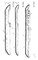
- FIG 1A shows a first embodiment of a computer system 2 according to the invention with a housing 1.
- the computer system 2 comprises a battery module 6 which can be removed from a base body 8 of the housing 1 and one or more system components arranged in the base body 8, for example various electronic components such as a motherboard with a processor and extension modules.
- a hinged display unit can be arranged on the main body 8 and other modules. These are for the sake of clarity in the Figure 1A but not shown.
- connection elements 10 or other user-accessible operating elements of the computer system 2 are arranged on the main body 8 of the housing 1.
- the battery module 6 is in the embodiment according to Figure 1A designed as a lower housing shell of the computer system 2.
- the relatively heavy battery module 6 serves as a footprint 9 for the computer system 2 and at the same time closes off the housing 1 of the computer system 2 downwards.
- the battery module 6 has a planar design and has substantially the same extent as the main body 8.
- CMOS battery for powering a BIOS module in the off state of the computer system.
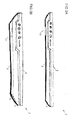
- FIGS. 1B and 1C It is shown that different battery modules 6a and 6b can be connected to the same basic body 8 to form a computer system 2. According to the embodiment described here, only a single one of the illustrated battery modules 6a and 6b is connected to the computer system 2 at any one time.
- the battery module 6a is relatively flat and has an average battery capacity, for example 48 Wh. For example, it has a height h 1 of less than five millimeters. Together with the main body 8, whose height is for example in the range of about ten to 15 millimeters, so a computer system 2 can be constructed, which does not exceed a total height of 20 millimeters.
- the tops of the battery modules 6a and 6b are made the same. Therefore, the flat battery module 6a can be replaced by the slightly thicker battery module 6b.
- the resulting computer system 2 then has a total of a higher overall height, but has the advantage of a significantly longer operating time.
- a rechargeable lithium-polymer battery is preferably used as the energy source.
- Lithium-polymer batteries constructed from film layers can be produced in almost any desired form, so that unlike cylindrical battery cells they can optimally utilize the available space for energy storage.
- the depression 11 serves to receive a first system component, for example a relatively thick expansion module 5.
- a DVD drive may be arranged in the region of the depression 11.
- a ventilation grille 13 is provided in a central region of the battery module 6.
- the battery module 6 is made thin and has passage openings.
- a cooling of individual electronic components of the computer system 2 is also possible from below through the battery module 6.
- connection pad 14 is furthermore provided on the upper side of the battery module 6, a connection pad 14 is furthermore provided.
- the connection field 14 serves for the electrical connection of the battery module 6 with at least one of the system components.
- these may be contact surfaces or contact springs, which interact with a corresponding contact spring or contact surface of the system component.
- a three-terminal panel 14 is provided which includes a positive, a negative, and a data terminal for communicating battery information to the motherboard 2.
- other connection fields for example, with less or more contact surfaces and other configurations, such as jack or post connector, find use.
- the battery module 6 additionally has a connection socket 15 for connecting an external power supply.
- the energy for charging the battery cell 7 and the operation of the computer system 2 is provided in network operation via the terminal 15 to the battery module 6 and forwarded from there via the connection pad 14 to the system component.
- FIG. 2B shows a cross section along the axis AA by the computer system 2 according to FIG. 2A , It can be seen here that the battery module 6 forms a lower housing cover, while the main circuit board 3 and the expansion module 5 are arranged in the main housing 8 forming the upper housing cover. Together they form the housing 1 of the computer system 2.
- a partition wall 18 is provided, which closes the main body 8 downwards.
- the battery module 6 and the surface of the system components are formed inversely or complementarily to each other. That is, the elevations of the system components penetrate into recesses 11 of the battery module 6 and penetrate elevations 12 of the battery module 6 in recesses of the system components or gaps between the system components.
- FIGS. 3A and 3B show a further embodiment of the invention.
- a computer system 2 comprising a main body 8 and a first battery module 6 is shown.
- the base body 8 may be constructed similarly to the one relating to Figure 1A described.
- the first battery module 6 is constructed similar to that with reference to FIGS Figure 1A described.
- the first battery module 6 is also according to FIG FIG. 3A designed as a bottom shell of the housing 1 of the computer system 2.
- the battery module 6 has a second connection pad 17 on the lower side of the housing 1 serving as a base 9.
- the second connection panel 17 is used for Coupling of the first battery module 6 with a further, second battery module 19, the in FIG. 3B is shown.
- FIG. 3B a computer system 2 with two battery modules 6 and 19 can be seen.
- the first battery module 6 corresponds to the battery module 6 shown in the upper part.
- the second battery module 19 is designed to be relatively flat and possesses an extent that essentially corresponds to the base area of the housing 1. It can be mechanically coupled to the first battery module 6 or the main body 8 of the housing 1. In the coupled state, the second battery module 19 serves as a base 9 for the computer system 2. At the same time, the battery capacity of the computer system 2 and thus its operating time is increased by receiving the second battery module 19.
- the further battery module 19 is configured symmetrically, that is, the contour and connection elements of its upper and lower sides are configured identically, by stacking further battery modules 19, the capacity of the computer system 2 can be increased almost as desired.
- the user of the computer system 2 can make an optimum balance between the thickness of the computer system 2 on the one hand and the capacity of the battery modules 6 and 19 contained therein on the other hand for its intended use.
- the battery module 6 is designed to be particularly flat and has an extent substantially equal to that of the display 23.
- a construction of the battery module 6 by means of layer foils with a thickness of a few micrometers in height is possible.
- a further battery cell 7 can be arranged in the form of the battery module 6.
Landscapes
- Engineering & Computer Science (AREA)
- Computer Hardware Design (AREA)
- Theoretical Computer Science (AREA)
- Physics & Mathematics (AREA)
- Human Computer Interaction (AREA)
- General Engineering & Computer Science (AREA)
- General Physics & Mathematics (AREA)
- Mathematical Physics (AREA)
- Power Engineering (AREA)
- Power Sources (AREA)
- Battery Mounting, Suspending (AREA)
Abstract
Description
- Die Erfindung betrifft ein Batterie betriebenes Computersystem umfassend wenigstens eine Systemkomponente zur Datenverarbeitung, wenigstens ein Gehäuse zur Aufnahme der Systemkomponente und wenigstens ein in das Gehäuse integriertes, austauschbares Batteriemodul zur Energieversorgung der Systemkomponente.
- Derartige Computersysteme sind vielfach bekannt. Insbesondere bei so genannten Notebook- oder Netbook-Computern ist es üblich, austauschbare Batteriemodule zur Stromversorgung von Systemkomponenten vorzusehen. Dabei handelt es sich in der Regel um Batteriemodule mit einer oder einer Vielzahl von zylinderförmigen, wiederaufladbaren Batteriezellen.
-
Figur 5A zeigt eine beispielhafte Anordnung eines konventionellen Notebooks. In einem Gehäuse 1 eines Computersystems 2 ist eine Hauptplatine 3 mit einem Prozessor 4 angeordnet. Zusätzlich ist in dem Computersystem 2 ein Erweiterungsmodul 5 angeordnet, beispielsweise ein Laufwerksmodul. Im rückwärtigen Bereich des Gehäuses 1 ist des Weiteren ein Batteriemodul 6 umfassend zwei Batteriezellen 7a und 7b angeordnet. Bei den Batteriezellen 7a und 7b handelt es sich um zylinderförmige, wiederaufladbare Lithium-Ionen-Zellen. Das Batteriemodul 6 wird in eine entsprechende Aussparung eines Grundkörpers 8 des Gehäuses 1 eingesetzt. - Ein Vorteil in der Verwendung von austauschbaren Batteriemodulen 6 liegt darin, dass im Falle von defekten oder leistungsschwachen Batteriezellen 7 das Batteriemodul 6 unabhängig vom Rest des Computersystems 2 ausgetauscht werden kann. Außerdem kann die Betriebsbereitschaft des Computersystems 2 durch Ersatz eines entladenen Batteriemoduls 6 mit einem geladenen Batteriemodul 6 schnell wieder hergestellt werden.
- Um eine möglichst lange Laufzeit des Computersystems 2 zu erreichen, werden bevorzugt Batteriezellen 7 mit besonders hoher Ladekapazität gewählt. Dies hat zur Folge, dass der von dem Batteriemodul 6 eingenommene Raum in dem Gehäuse 1 verhältnismäßig groß ist.
-
Figur 5B zeigt eine Seitenansicht des Computersystems 2 mit dem Batteriemodul 6. Das Gehäuse 1 des Computersystems 2 verdickt sich nach hinten. Dadurch kann eine Batteriezelle 7 mit verhältnismäßig großem Durchmesser in dem Gehäuse 1 angeordnet werden. - Um die Betriebsdauer des Computersystems 2 noch weiter zu erhöhen, kann ein Batteriemodul 6 mit einer größeren Anzahl von Batteriezellen 7 verwendet werden, das gegenüber dem in der
Figur 5B dargestellten Batteriemodul 6 eine vergrößerte Batteriekapazität aufweist. -
Figur 5C zeigt ein Computersystem 2 umfassend ein solches Hochkapazitätsbatteriemodul 6. Wie aus derFigur 5C ersichtlich, steht das Hochkapazitätsbatteriemodul 6 in der Regel nach hinten oder nach unten über die Abmessungen des Gehäuses 1 des Computersystems 2 hinaus. Hervorstehende Teile sind insbesondere im mobilen Betrieb des Computersystems 2 unpraktisch. Darüber hinaus ändern sie möglicherweise den Anstellwinkel einer in das Gehäuse 1 integrierten Tastatur. - Eine Aufgabe der vorliegenden Erfindung ist es, ein Batterie betriebenes Computersystem zu beschreiben, das eine Erhöhung der Laufzeit des Computersystems ohne oder mit nur geringen Auswirkungen auf dessen Bauform ermöglicht. Darüber hinaus soll ein Batterie betriebenes Computersystem beschrieben werden, das eine modulare Kapazitätserhöhung gestattet, ohne dass sich die Gehäuseproportionen oder die Neigung einer Gehäuseoberfläche ändern.
- Die oben genannte Aufgabe wird durch ein gattungsgemäßes Computersystem gelöst, in dem das Batteriemodul flach ausgestaltet ist, eine Ausdehnung besitzt, die im Wesentlichen einer Grundfläche des Gehäuses entspricht, und einen Gehäusedeckel des Gehäuses bildet. Erfindungsgemäß ist das Batteriemodul als Bodenschale des Gehäuses ausgestaltet.
- Durch die Ausgestaltung des Batteriemoduls als flacher Gehäusedeckel, dessen Ausdehnung im Wesentlichen einer Grundfläche des Gehäuses entspricht, können verhältnismäßig großvolumige Batteriemodule verwendet werden, die nicht zu einer wesentlichen Vergrößerung eines Gehäuses des Computersystems führen. Die Ausgestaltung eines Batteriemoduls als Bodenschale eines Gehäuses besitzt den Vorteil, dass der gesamte im Bodenbereich des Computersystems zur Verfügung stehende Raum zur Bereitstellung von Batteriekapazität genutzt werden kann. Gleichzeitig bedingt die verhältnismäßig hohe Dichte des Batteriemoduls einen sicheren Stand des Computersystems.
- Gemäß einer vorteilhaften Ausgestaltung ragt das als Gehäusedeckel ausgestaltete Batteriemodul zumindest teilweise in wenigstens einen in dem Gehäuse verbleibenden Hohlraum, insbesondere eine Aussparung der wenigstens einen Systemkomponente oder einen Zwischenraum zwischen zwei benachbarten Systemkomponenten, hinein. Auf diese Weise können in dem Computersystem vorhandene Hohlräume zur Erhöhung der Batteriekapazität verwendet werden.
- Gemäß einer vorteilhaften Ausgestaltung umfasst das Computersystem eine Mehrzahl von Komponenten, die zusammengenommen eine Oberflächenstruktur bilden, und das als Gehäusedeckel ausgestaltete Batteriemodul weist eine inverse Oberflächenstruktur auf, die im in das Computersystem aufgenommenen Zustand den zur Verfügung stehenden Raum im Wesentlichen vollständig ausfüllt. Durch die Ausfüllung sämtlicher zur Verfügung stehender Hohlräume wird die Batteriekapazität des Batterie betriebenen Computersystems optimiert.
- Gemäß einer vorteilhaften Ausgestaltung umfasst das Batteriemodul eine plastische Substanz zur Speicherung von Energie, die den als Batteriemodul ausgestalteten Gehäusedeckel im Wesentlichen vollständig ausfüllt. Durch die Verwendung einer plastischen Substanz zur Speicherung von Energie kann der gesamte zur Verfügung stehende Raum zur Erhöhung der Batteriekapazität verwendet werden.
- Gemäß einer weiteren vorteilhaften Ausgestaltung umfasst das Batterie betriebene Computersystem wenigstens ein weiteres flaches Batteriemodul, das eine Ausdehnung besitzt, die im Wesentlichen der Grundfläche des Gehäuses entspricht, wobei das weitere Batteriemodul zwischen dem als Gehäusedeckel ausgestalteten Batteriemodul und der Systemkomponente angeordnet ist.
- Durch die Anordnung eines weiteren Batteriemoduls zwischen dem als Gehäusedeckel ausgestalteten Batteriemodul und der Systemkomponente kann die Batteriekapazität des Batterie betriebenen Computersystems weiter erhöht werden. Dabei bleibt die Grundform des Gehäuses des Computersystems weitgehend unberührt. Insbesondere kann die Batteriekapazität des Computersystems linear mit einer Dicke des Computersystems vergrößert werden.
- Die Erfindung wird nachfolgend anhand von unterschiedlichen Ausführungsbeispielen und Figuren näher beschrieben. Dabei werden für gleiche oder gleich wirkende Komponente einheitliche Bezugszeichen in den unterschiedlichen Ausführungsbeispielen und Figuren verwendet.
-
- Figur 1
- eine Ausgestaltung eines Computersystems mit einem als Bodenschale ausgebildeten Batteriemodul,
- Figur 2
- eine Aufsicht auf und einen Querschnitt durch ein Batteriemodul gemäß einer Ausgestaltung der Erfindung,
- Figur 3
- eine weitere Ausgestaltung eines Computersystems mit zwei übereinander angeordneten Batteriemodulen,
- Figur 4
- eine weitere Ausgestaltung eines Computersystems mit einem als Gehäusedeckel ausgebildeten Batteriemodul und
- Figur 5
- Anordnungen von Komponenten in konventionellen Computersystemen mit unterschiedlichen Batteriemodulen.
-
Figur 1A zeigt eine erste Ausgestaltung eines erfindungsgemäßen Computersystems 2 mit einem Gehäuse 1. Das Computersystem 2 umfasst ein von einem Grundkörper 8 des Gehäuses 1 abnehmbares Batteriemodul 6 sowie ein oder mehrere in dem Grundkörper 8 angeordnete Systemkomponenten, beispielsweise verschiedene elektronische Baugruppen wie eine Hauptplatine mit einem Prozessor und Erweiterungsmodule. An dem Grundkörper 8 können auch weitere Baugruppen, insbesondere eine klappbare Anzeigeeinheit angeordnet sein. Diese sind der Übersichtlichkeit halber in derFigur 1A jedoch nicht dargestellt. - In der Seitenansicht gemäß der
Figur 1A ist jedoch zu erkennen, dass Anschlusselemente 10 oder andere für den Benutzer zugängliche Bedienelemente des Computersystems 2 an dem Grundkörper 8 des Gehäuses 1 angeordnet sind. - Das Batteriemodul 6 ist in der Ausgestaltung gemäß
Figur 1A als untere Gehäuseschale des Computersystems 2 ausgestaltet. Das verhältnismäßig schwere Batteriemodul 6 dient als Standfläche 9 für das Computersystem 2 und schließt gleichzeitig das Gehäuse 1 des Computersystems 2 nach unten hin ab. Das Batteriemodul 6 ist flächig ausgestaltet und besitzt im Wesentlichen dieselbe Ausdehnung wie der Grundkörper 8. - Weitere Batteriezellen zur Versorgung der Systemkomponenten mit einem Betriebsstrom sind in dem Computersystem gemäß
Figur 1A nicht vorgesehen. Insbesondere umfasst der als Oberschale des Gehäuses 1 dienende Grundkörper 8 kein weiteres Batteriemodul. Allerdings kann zur Speicherung von Systemzuständen eine Hilfsbatterie vorgesehen sein, die ausgewählte Komponenten mit einem Bereitschaftsstrom versorgt, insbesondere eine so genannte CMOS-Batterie zur Stromversorgung eines BIOS-Bausteins im ausgeschalteten Zustand des Computersystems 2. - In den
Figuren 1B und 1C ist dargestellt, dass unterschiedliche Batteriemodule 6a bzw. 6b mit demselben Grundkörper 8 zu einem Computersystem 2 verbunden werden können. Gemäß der hier beschriebenen Ausgestaltung ist zu jedem Zeitpunkt nur ein einzelnes der dargestellten Batteriemodule 6a und 6b mit dem Computersystem 2 verbunden. - Das Batteriemodul 6a ist verhältnismäßig flach ausgestaltet und weist eine mittlere Batteriekapazität, zum Beispiel 48 Wh auf. Beispielsweise weist es eine Höhe h1 von weniger als fünf Millimeter auf. Zusammen mit dem Grundkörper 8, dessen Höhe beispielsweise im Bereich von etwa zehn bis 15 Millimeter liegt, kann so ein Computersystem 2 aufgebaut werden, das eine Gesamthöhe von 20 Millimeter nicht überschreitet.
- Das Batteriemodul 6b weist eine größere Bauhöhe h = h1 + h2 auf als das Batteriemodul 6a. Beispielsweise kann es eine Höhe von fünf bis 20 Millimeter, beispielsweise 10 oder 15 Millimeter, aufweisen. Durch die zusätzliche Höhe h2 weist das Batteriemodul 6b ein wesentlich größeres Volumen V = V1 + V2 auf. Wird das Volumen V vollständig von einer in das Batteriemodul 6 angeordneten Batteriezelle 7 ausgefüllt, erhöht sich dessen Speicherkapazität entsprechend der Volumenzunahme, beispielsweise auf eine Kapazität von 96 Wh.
- Die Oberseiten der Batteriemodule 6a und 6b sind gleich ausgestaltet. Daher kann das flache Batteriemodul 6a durch das etwas dickere Batteriemodul 6b ersetzt werden. Das sich ergebende Computersystem 2 weist dann insgesamt zwar eine höhere Bauhöhe auf, besitzt jedoch den Vorteil einer deutlich längeren Betriebszeit.
- Um das Volumen der Batteriemodule 6a beziehungsweise 6b optimal zur Speicherung von elektrischer Energie auszunutzen, wird bevorzugt eine wiederaufladbare Lithium-Polymer-Batterie als Energiequelle verwendet. Aus Folienschichten aufgebaute Lithium-Polymer-Batterien lassen sich in beinahe jeder beliebigen Form herstellen, so dass sie im Gegensatz zu zylinderförmigen Batteriezellen den zur Verfügung stehenden Raum optimal zur Energiespeicherung ausnutzen können.
- Auch andere Vorrichtungen zur Speicherung von Energie können in dem erfindungsgemäßen Batteriemodul 6 Verwendung finden, sofern sie aufgrund ihrer physikalischen Eigenschaften geeignet sind, ein flächig ausgestaltetes Batteriemodul 6 weitgehend vollständig zur Speicherung von Energie zu nutzen. Hierfür eignen sich insbesondere derartige Anordnungen, bei denen eine plastische Substanz zur Speicherung von Energie verwendet wird.
-
Figur 2A zeigt eine Aufsicht auf ein Batteriemodul 6. Im in derFigur 2A dargestellten Ausführungsbeispiel weist das Batteriemodul 6 eine unebene Oberfläche auf, die im zusammengesetzten Zustand bündig mit einem Grundkörper 8 eines Computersystems 2 abschließt und dessen Gehäusedeckel, insbesondere dessen Bodenschale, bildet. Im dargestellten Ausführungsbeispiel weist das Batteriemodul 6 eine wannenförmige Vertiefung 11 und zwei Erhebungen 12a und 12b auf. - Die Vertiefung 11 dient zur Aufnahme einer ersten Systemkomponente, beispielsweise einem verhältnismäßig dicken Erweiterungsmodul 5. Beispielsweise kann im Bereich der Vertiefung 11 ein DVD-Laufwerk angeordnet sein. Durch die Vertiefung 11 in dem Batteriemodul 6 kann trotz der Verwendung verhältnismäßig hoher Einzelkomponenten eine besonders flache Bauweise des Computersystems 2 gewährleistet werden.
- Umgekehrt vergrößern die Erhebungen 12a und 12b das Volumen des Batteriemoduls 6 und somit die Speicherkapazität der darin integrierten Batteriezelle 7. Beispielsweise kann die Erhebung 12a in einen Hohlraum einer zweiten Systemkomponente eindringen, beispielsweise in eine Ausnehmung einer Hauptplatine 3 oder Bereiche der Hauptplatine 3, in denen keine weiteren elektronischen Komponenten angeordnet sind. Die Erhebung 12b ist in einem Bereich vorgesehen, in dem sich keine Systemkomponente befindet, im Ausführungsbeispiel in einem Zwischenbereich zwischen der Hauptplatine 3 und dem Erweiterungsmodul 5. Zum besseren Verständnis ist die in Projektionsrichtung der
Figur 2A über dem Batteriemodul 6 angeordnete Hauptplatine 3 gestrichelt dargestellt. - Darüber hinaus weist das Batteriemodul 6 gemäß
Figur 2A weitere, optionale Merkmale auf. Beispielsweise ist in einem zentralen Bereich des Batteriemoduls 6 ein Lüftungsgitter 13 vorgesehen. Im Bereich des Lüftungsgitters 13 ist das Batteriemodul 6 dünn ausgestaltet und weist Durchtrittsöffnungen auf. Somit ist eine Kühlung von einzelnen elektronischen Komponenten des Computersystems 2 auch von unten her durch das Batteriemodul 6 möglich. - Auf der Oberseite des Batteriemoduls 6 ist des Weiteren ein Anschlussfeld 14 vorgesehen. Das Anschlussfeld 14 dient zur elektrischen Verbindung des Batteriemoduls 6 mit wenigstens einer der Systemkomponenten. Beispielsweise kann es sich dabei um Kontaktflächen oder Kontaktfedern handeln, die mit einer entsprechenden Kontaktfeder beziehungsweise Kontaktfläche der Systemkomponente zusammenwirken. Im Ausführungsbeispiel ist ein dreipoliges Anschlussfeld 14 vorgesehen, das einen positiven, einen negativen sowie einen Datenanschluss zum Übermitteln von Batterieinformationen an die Hauptplatine 2 umfasst. Selbstverständlich können auch andere Anschlussfelder, beispielsweise mit weniger oder mehr Kontaktflächen und andere Ausgestaltungen, wie beispielsweise Klinken- oder Pfostenstecker, Verwendung finden.
- Im Ausführungsbeispiel weist das Batteriemodul 6 zusätzlich eine Anschlussbuchse 15 zum Anschluss eines externen Netzteils auf. Somit wird die Energie zum Laden der Batteriezelle 7 sowie zum Betrieb des Computersystems 2 bei Netzbetrieb über den Anschluss 15 an das Batteriemodul 6 bereitgestellt und von dort über das Anschlussfeld 14 an die Systemkomponente weitergeleitet. Alternativ ist es auch möglich, den Anschluss 15 an dem Grundkörper 8 bzw. der Hauptplatine 3 vorzusehen, und sowohl einen Ladestrom als auch einen Entladestrom des Batteriemoduls 6 über das Anschlussfeld 14 zu übertragen.
- Zur mechanischen Befestigung des Batteriemoduls 6 an dem Grundkörper 8 des Gehäuses 1 weist das Batteriemodul 6 gemäß
Figur 2A vier Rastelemente 16 auf. Die Rastelemente 16 sind im Ausführungsbeispiel in der Nähe der vier Ecken des Batteriemoduls 6 angeordnet und dienen zur sicheren Verrastung des Batteriemoduls 6 mit dem Grundkörper 8 des Computersystems 2. Durch Eindrücken der Rastelemente 16 kann das Batteriemodul 6 von dem Grundkörper 8 gelöst werden. Selbstverständlich sind auch andere, aus dem Stand der Technik bekannte Befestigungselemente zur Befestigung des Batteriemoduls 6 möglich. Beispielsweise kann eine Kunststoff ummantelte Batteriezelle 7 mittels einer aus Aluminium gefertigten Bodenschale an dem Gehäuse 1 befestigt und in dessen Design integriert werden. -
Figur 2B zeigt einen Querschnitt entlang der Achse A-A durch das Computersystem 2 gemäßFigur 2A . Darin ist zu erkennen, dass das Batteriemodul 6 einen unteren Gehäusedeckel bildet, während die Hauptplatine 3 und das Erweiterungsmodul 5 im den oberen Gehäusedeckel bildenden Grundkörper 8 angeordnet sind. Zusammen bilden sie das Gehäuse 1 des Computersystems 2. - Zum Schutz der einzelnen Systemkomponenten, also im Ausführungsbeispiel der Hauptplatine 3 und des Erweiterungsmoduls 5, ist eine Trennwand 18 vorgesehen, die den Grundkörper 8 nach unten hin abschließt. Bezüglich der Trennwand 18 sind das Batteriemodul 6 und die Oberfläche der Systemkomponenten zueinander invers oder komplementär ausgebildet. Das heißt, das Erhebungen der Systemkomponenten in Aussparungen 11 des Batteriemoduls 6 eindringen und Erhebungen 12 des Batteriemoduls 6 in Aussparungen der Systemkomponenten oder Lücken zwischen den Systemkomponenten eindringen.
- Die
Figuren 3A und 3B zeigen eine weitere Ausgestaltung der Erfindung. In derFigur 3A ist ein Computersystem 2 umfassend einen Grundkörper 8 und ein erstes Batteriemodul 6 dargestellt. Beispielsweise kann der Grundkörper 8 ähnlich aufgebaut sein wie der bezüglichFigur 1A beschriebene. Auch das erste Batteriemodul 6 ist ähnlich aufgebaut wie das unter Bezugnahme auf dieFigur 1A beschriebene. Insbesondere ist auch das erste Batteriemodul 6 gemäßFigur 3A als Bodenschale des Gehäuses 1 des Computersystems 2 ausgestaltet. - Darüber hinaus weist das Batteriemodul 6 jedoch ein zweites Anschlussfeld 17 an der als Standfläche 9 dienenden Unterseite des Gehäuses 1 auf. Das zweite Anschlussfeld 17 dient zur Kopplung des ersten Batteriemoduls 6 mit einem weiteren, zweiten Batteriemodul 19, das in
Figur 3B dargestellt ist. - In der
Figur 3B ist ein Computersystem 2 mit zwei Batteriemodulen 6 und 19 zu erkennen. Dabei entspricht das ersten Batteriemodul 6 dem im oberen Teil dargestellten Batteriemodul 6. Auch das zweite Batteriemodul 19 ist verhältnismäßig flach ausgestaltet und besitz eine Ausdehnung, die im Wesentlichen der Grundfläche des Gehäuses 1 entspricht. Es kann an das erste Batteriemodul 6 oder den Grundkörper 8 des Gehäuses 1 mechanisch angekoppelt werden. Im angekoppelten Zustand dient das zweite Batteriemodul 19 als Standfläche 9 für das Computersystem 2. Gleichzeitig wird die Batteriekapazität des Computersystems 2 und damit dessen Betriebsdauer durch Aufnahme des zweiten Batteriemoduls 19 erhöht. - In dem in der
Figur 3B dargestellten Ausführungsbeispiel weist das weitere Batteriemodul 19 eine geringfügig kleinere Flächenausdehnung auf, als das darüber angeordnete erste Batteriemodul 6. Auf diese Weise lässt sich das weitere Batteriemodul 19 auf ästhetisch ansprechende Weise in das Gehäuse 1 des Computersystems 2 integrieren. - In einer alternativen, in den Figuren nicht dargestellten Ausgestaltung wird ein zweites Batteriemodul 19 zwischen einem als Bodenschale ausgestalteten ersten Batteriemodul 6 und dem Grundkörper 8 angeordnet. Beispielsweise kann ein zweites Batteriemodul 19 mit einer Bauhöhe von wenigen Millimetern, zum Beispiel vier Millimetern, zwischen dem als Bodendeckel ausgebildeten ersten Batteriemoduls 6 und dem Grundkörper 8 angeordnet werden. Bevorzugt schleift das zweite Batteriemodul 19 das elektrische Anschlussfeld 14 des ersten Batteriemoduls 6 zu einem entsprechenden Anschlusselement des Grundkörpers 8 durch. Das erste Batteriemodul 6 gemäß dieser Ausgestaltung bedarf daher keines zweiten Anschlussmoduls 17. Das zweite Batteriemodul 19 dient wiederum zur Erhöhung der Kapazität und somit zu einem verlängerten Betrieb des Computersystems 2.
- Ist das weitere Batteriemodul 19 symmetrisch ausgestaltet, das heißt sind die Kontur und Anschlusselemente seiner Ober- und Unterseiten gleichartig ausgestaltet, kann durch Aufeinanderstapeln weiterer Batteriemodule 19 die Kapazität des Computersystems 2 nahezu beliebig vergrößert werden. Somit kann der Benutzer des Computersystems 2 eine für seinen Gebrauchszweck optimale Abwägung zwischen Dicke des Computersystems 2 einerseits und Kapazität der darin enthaltenden Batteriemodule 6 beziehungsweise 19 andererseits vornehmen.
-
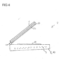
Figur 4 zeigt ein weiteres Batterie betriebenen Computersystems 2. Ein Gehäuse 1 des Computersystems 2 umfasst einen Grundkörper 8 in dem unter anderem eine Hauptplatine 3 sowie eine Tastatur 20 als Systemkomponenten aufgenommen sind. Über ein Scharnier 21 ist ein klappbarer Gehäuseteil 22 mit dem Grundkörper 8 verbunden. Das Gehäuseteil 22 umfasst eine weitere Systemkomponente, nämlich eine Anzeige 23, insbesondere eine Flüssigkristallanzeige. - Um das Computersystem 2 mit Energie zu versorgen und um eine bereits in den Grundkörper 8 integrierte Batteriezelle zu erweitern, umfasst das Gehäuseteil 22 zusätzlich ein Batteriemodul 6, das einen oberen Gehäusedeckel des Gehäuses 1 bildet. Bevorzugt ist das Batteriemodul 6 wiederum abnehmbar an dem Gehäuseteil 22 befestigt, beispielsweise hinter einer Abdeckung angeordnet oder mit dem Gehäuseteil 22 verrastet.
- Wie in den zuvor beschriebenen Ausführungsbeispielen ist das Batteriemodul 6 besonders flach ausgestaltet und besitzt im Wesentlichen eine Ausdehnung, die der der Anzeige 23 entspricht. Insbesondere bei der Verwendung von Lithium-Polymer-Zellen ist ein Aufbau des Batteriemoduls 6 mit Hilfe von Schichtfolien mit einer Dicke von einigen Mikrometern Höhe möglich. Somit kann selbst in dem Gehäuseteil 22 eine weitere Batteriezelle 7 in Form des Batteriemoduls 6 angeordnet werden.
- Um die mechanische Stabilität des Computersystems 2 nicht nachteilig zu beeinflussen, insbesondere um die Standsicherheit des Computersystems 2 sicherzustellen, empfiehlt sich die Verwendung eines in dem Gehäuseteil 22 angeordneten Batteriemoduls 6 insbesondere dann, wenn der Grundkörper 8 verhältnismäßig schwer ausgestaltet ist. Dies wird unter anderem dadurch bewirkt, dass die Bodenschale des Grundkörpers 8 als weiteres Batteriemodul 19 ausgestaltet ist. Wird somit sowohl in dem Grundkörper 8 als auch in dem Gehäuseteil 22 des Gehäuses 1 ein Batteriemodul 6 beziehungsweise 19 integriert, kann die Batteriekapazität des Computersystems 2 noch weiter vergrößert werden.
- Weitere Abwandlungen und Ausgestaltungen der in den Ausführungsbeispielen beschriebenen Konzepte sind möglich. Insbesondere können die einzelnen Elemente der unterschiedlichen Ausführungsbeispiele miteinander kombiniert werden, so dass ein Computersystem 2 mit einer Vielzahl von unterschiedlichen ausgestalteten Batteriemodulen 6 und 19 entsteht.
- Bezugszeichen
- 1
- Gehäuse
- 2
- Computersystem
- 3
- Hauptplatine
- 4
- Prozessor
- 5
- Erweiterungsmodul
- 6
- (erstes) Batteriemodul
- 7
- Batteriezelle
- 8
- Grundkörper
- 9
- Standfläche
- 10
- Anschlusselement
- 11
- Vertiefung
- 12
- Erhebung
- 13
- Lüftungsgitter
- 14
- (erstes) Anschlussfeld
- 15
- Anschluss
- 16
- Rastelement
- 17
- (zweites) Anschlussfeld
- 18
- Trennwand
- 19
- (zweites) Batteriemodul
- 20
- Tastatur
- 21
- Scharnier
- 22
- Gehäuseteil
- 23
- Anzeige
Claims (10)
- Batterie betriebenes Computersystem (2), umfassend: wenigstens eine Systemkomponente zur Datenverarbeitung, wenigstens ein Gehäuse (1) zur Aufnahme der Systemkomponente und wenigstens ein in das Gehäuse (1) integriertes, austauschbares Batteriemodul (6) zur Energieversorgung der Systemkomponente, wobei das Batteriemodul (6) als flache Bodenschale ausgestaltet ist, eine Ausdehnung besitzt, die im Wesentlichen einer Grundfläche des Gehäuses (1) entspricht, und einen unteren Gehäusedeckel des Gehäuses (1) bildet.
- Batterie betriebenes Computersystem (2) nach Anspruch 1,
dadurch gekennzeichnet, dass
die Bodenschale als Standfläche (9) des Computersystems (2) im Normalbetrieb ausgebildet ist. - Batterie betriebenes Computersystem (2) nach Anspruch 1 oder 2,
dadurch gekennzeichnet, dass
das Gehäuse einen Grundkörper (8) sowie ein damit beweglich verbundenes Gehäuseteil (22) umfasst und ein zweites Batteriemodul (6) als oberer Gehäusedeckel des Gehäuseteils (22) ausgestaltet ist. - Batterie betriebenes Computersystem (2) nach einem der Ansprüche 1 bis 3, dadurch gekennzeichnet, dass
zwischen der wenigstens einen Systemkomponente und dem als Batteriemodul (6) ausgebildeten Gehäusedeckel eine Trennwand (18) zur elektrischen Isolation angeordnet ist. - Batterie betriebenes Computersystem (2) nach einem der Ansprüche 1 bis 4, dadurch gekennzeichnet, dass
das als Gehäusedeckel ausgestaltete Batteriemodul (6) zumindest teilweise in wenigstens einen in dem Gehäuse (1) verbleibenden Hohlraum, insbesondere eine Aussparung der wenigstens einen Systemkomponente oder in einen Zwischenraum zwischen zwei benachbarten Systemkomponenten, hineinragt. - Batterie betriebenes Computersystem (2) nach Anspruch 5,
dadurch gekennzeichnet, dass
das Computersystem (2) eine Mehrzahl von Systemkomponenten umfasst, die zusammengenommen eine Oberflächenstruktur bilden, und das als Gehäusedeckel ausgestaltete Batteriemodul (6) eine inverse Oberflächenstruktur aufweist, die im in das Computersystem (2) aufgenommenen Zustand den zur Verfügung stehenden Raum im Wesentlichen vollständig ausfüllt. - Batterie betriebenes Computersystem (2) nach einem der Ansprüche 1 bis 6, dadurch gekennzeichnet, dass
das Batteriemodul (6) eine plastische Substanz zur Speicherung von Energie umfasst, die den als Batteriemodul (6) ausgestalteten Gehäusedeckel im Wesentlichen vollständig ausfüllt. - Batterie betriebenes Computersystem (2) nach Anspruch 7,
dadurch gekennzeichnet, dass
das Batteriemodul (6) eine wiederaufladbare Lithium-Polymer-Batterie umfasst. - Batterie betriebenes Computersystem (2) nach einem der Ansprüche 1 bis 8, dadurch gekennzeichnet, dass
das Batterie betriebene Computersystem (2) wenigstens ein weiteres flaches Batteriemodul (19) umfasst, das eine Ausdehnung besitzt, die im Wesentlichen der Grundfläche des Gehäuses (1) entspricht, wobei das weitere Batteriemodul (19) zwischen dem als Gehäusedeckel ausgestalteten Batteriemodul (6) und der Systemkomponente angeordnet ist. - Batterie betriebenes Computersystem (2) nach Anspruch 9,
dadurch gekennzeichnet, dass
das weitere Batteriemodul (19) bezüglich einer Ober- und Unterseite im Wesentlichen symmetrisch aufgebaut ist, so dass mehrere Batteriemodule (19) stapelbar sind.
Applications Claiming Priority (1)
| Application Number | Priority Date | Filing Date | Title |
|---|---|---|---|
| DE200910010470 DE102009010470B4 (de) | 2009-02-26 | 2009-02-26 | Batterie betriebenes Computersystem |
Publications (3)
| Publication Number | Publication Date |
|---|---|
| EP2224309A2 true EP2224309A2 (de) | 2010-09-01 |
| EP2224309A3 EP2224309A3 (de) | 2011-08-03 |
| EP2224309B1 EP2224309B1 (de) | 2015-03-04 |
Family
ID=42199869
Family Applications (1)
| Application Number | Title | Priority Date | Filing Date |
|---|---|---|---|
| EP20090170319 Not-in-force EP2224309B1 (de) | 2009-02-26 | 2009-09-15 | Batterie betriebenes Computersystem |
Country Status (2)
| Country | Link |
|---|---|
| EP (1) | EP2224309B1 (de) |
| DE (1) | DE102009010470B4 (de) |
Citations (2)
| Publication number | Priority date | Publication date | Assignee | Title |
|---|---|---|---|---|
| US20040233630A1 (en) | 2003-02-28 | 2004-11-25 | Akira Imamura | Electronic apparatus with a removable component |
| US20050189922A1 (en) | 2004-03-01 | 2005-09-01 | Arif Maskatia | Portable electronic apparatus including detachable system and expansion modules |
Family Cites Families (4)
| Publication number | Priority date | Publication date | Assignee | Title |
|---|---|---|---|---|
| SE519632C2 (sv) * | 1997-12-23 | 2003-03-25 | Ericsson Telefon Ab L M | Portabel elektronisk apparat med tunnfilmsbatterier samt dessas användning i densamma |
| JP3945986B2 (ja) * | 1999-03-10 | 2007-07-18 | 富士通株式会社 | 電子機器 |
| US6256192B1 (en) * | 1999-08-09 | 2001-07-03 | Packard Bell Nec, Inc. | Accordion-fold laptop computer |
| DE10327964A1 (de) * | 2003-06-19 | 2005-01-05 | Joachim Schweizer | Deckeleinheit für ein Notebook |
-
2009
- 2009-02-26 DE DE200910010470 patent/DE102009010470B4/de not_active Expired - Fee Related
- 2009-09-15 EP EP20090170319 patent/EP2224309B1/de not_active Not-in-force
Patent Citations (2)
| Publication number | Priority date | Publication date | Assignee | Title |
|---|---|---|---|---|
| US20040233630A1 (en) | 2003-02-28 | 2004-11-25 | Akira Imamura | Electronic apparatus with a removable component |
| US20050189922A1 (en) | 2004-03-01 | 2005-09-01 | Arif Maskatia | Portable electronic apparatus including detachable system and expansion modules |
Also Published As
| Publication number | Publication date |
|---|---|
| DE102009010470B4 (de) | 2011-06-22 |
| DE102009010470A1 (de) | 2010-09-09 |
| EP2224309B1 (de) | 2015-03-04 |
| EP2224309A3 (de) | 2011-08-03 |
Similar Documents
| Publication | Publication Date | Title |
|---|---|---|
| DE69812422T2 (de) | Tragbare elektronische vorrichtung mit batteriegespeisten komponenten | |
| DE102010024235B4 (de) | Akkumulatorzelle und Batterie | |
| EP3435440B1 (de) | Speichermodul zum bereitstellen elektrischer energie umfassend einfassmodul, anordnung sowie transportfahrzeug enthaltend das speichermodul | |
| DE102011076981A1 (de) | Batteriesystem, Kraftfahrzeug mit diesem Batteriesystem und Verfahren zur Herstellung einer Betriebsbereitschaft bei einem Kraftfahrzeug mit diesem Batteriesystem | |
| EP3396733B1 (de) | System bestehend aus einer aufnahmeeinrichtung und in der aufnahmeeinrichtung anzuordnenden energiespeichern, aufnahmeeinrichtung und träger zur aufnahme von energiespeichern | |
| EP2700611B1 (de) | Adapterrahmen für Traktionsbatterie sowie Flurförderzeug mit Traktionsbatterie | |
| WO2001071465A2 (de) | Tragbares computersystem | |
| DE102010013024A1 (de) | Batterie aus einer Vielzahl von Batterieeinzelzellen | |
| DE10039621A1 (de) | Batterieeinheit und elektronische Vorrichtung | |
| DE102014112802B4 (de) | Kühlkontakt für eine Sekundärbatterie | |
| DE202023003137U1 (de) | Batterie und stromverbrauchendes Gerät | |
| EP3959755A1 (de) | Energiespeichervorrichtung und fahrzeug | |
| WO2012136337A1 (de) | Energiespeicheranordnung und energiespeichervorrichtung | |
| DE102018215580B4 (de) | Hochvoltbatterie aufweisend Batteriezellen mit einzelwandigen und doppelwandigen Zellgehäusen sowie Kraftfahrzeug | |
| DE102015216181B3 (de) | Elektrischer Energiespeicher mit Speichermodulen unterschiedlichen Typs | |
| DE202023103373U1 (de) | Mobile Stromversorgung, mobile Stromversorgung-Verwaltungsvorrichtung, und mobiles Stromversorgungssystem | |
| EP2224309B1 (de) | Batterie betriebenes Computersystem | |
| EP2856535B1 (de) | Speicherelement umfassend mehrere lithium-zellen | |
| WO2011012206A1 (de) | Zellenverbund mit einer vorgebbaren anzahl von parallel und/oder seriell miteinander verschalteten einzelzellen | |
| EP3061143A1 (de) | Gitteranordnung für eine plattenförmige batterieelektrode und akkumulator | |
| DE102023002549A1 (de) | Antriebsmodul und Fahrzeug mit einem solchen Antriebsmodul | |
| DE4300763C2 (de) | Bleiakkumulator mit mindestens einer bipolaren Elektrode | |
| DE102011089086A1 (de) | Elektrisches Energiespeichermodul und Verfahren zum Herstellen eines elektrischen Energiespeichermoduls | |
| DE102023109712A1 (de) | Vorrichtung für eine prismatische batteriezelle mit eingebauten federn | |
| DE102025121757A1 (de) | Struktur und verfahren zur befestigung eines batteriemoduls an einem batteriepack |
Legal Events
| Date | Code | Title | Description |
|---|---|---|---|
| PUAI | Public reference made under article 153(3) epc to a published international application that has entered the european phase |
Free format text: ORIGINAL CODE: 0009012 |
|
| AK | Designated contracting states |
Kind code of ref document: A2 Designated state(s): AT BE BG CH CY CZ DE DK EE ES FI FR GB GR HR HU IE IS IT LI LT LU LV MC MK MT NL NO PL PT RO SE SI SK SM TR |
|
| AX | Request for extension of the european patent |
Extension state: AL BA RS |
|
| RAP1 | Party data changed (applicant data changed or rights of an application transferred) |
Owner name: FUJITSU TECHNOLOGY SOLUTIONS INTELLECTUAL PROPERTY |
|
| RIC1 | Information provided on ipc code assigned before grant |
Ipc: G06F 1/18 20060101ALI20110225BHEP Ipc: G06F 1/16 20060101AFI20100603BHEP |
|
| PUAL | Search report despatched |
Free format text: ORIGINAL CODE: 0009013 |
|
| AK | Designated contracting states |
Kind code of ref document: A3 Designated state(s): AT BE BG CH CY CZ DE DK EE ES FI FR GB GR HR HU IE IS IT LI LT LU LV MC MK MT NL NO PL PT RO SE SI SK SM TR |
|
| AX | Request for extension of the european patent |
Extension state: AL BA RS |
|
| RIC1 | Information provided on ipc code assigned before grant |
Ipc: G06F 1/16 20060101AFI20110628BHEP Ipc: G06F 1/18 20060101ALI20110628BHEP |
|
| 17P | Request for examination filed |
Effective date: 20120202 |
|
| 17Q | First examination report despatched |
Effective date: 20130617 |
|
| GRAP | Despatch of communication of intention to grant a patent |
Free format text: ORIGINAL CODE: EPIDOSNIGR1 |
|
| INTG | Intention to grant announced |
Effective date: 20141029 |
|
| GRAS | Grant fee paid |
Free format text: ORIGINAL CODE: EPIDOSNIGR3 |
|
| GRAA | (expected) grant |
Free format text: ORIGINAL CODE: 0009210 |
|
| RBV | Designated contracting states (corrected) |
Designated state(s): AT BE BG CH CY CZ DK EE ES FI FR GB GR HR HU IE IS IT LI LT LU LV MC MK MT NL NO PL PT RO SE SI SK SM TR |
|
| REG | Reference to a national code |
Ref country code: DE Ref legal event code: R108 |
|
| AK | Designated contracting states |
Kind code of ref document: B1 Designated state(s): AT BE BG CH CY CZ DK EE ES FI FR GB GR HR HU IE IS IT LI LT LU LV MC MK MT NL NO PL PT RO SE SI SK SM TR |
|
| REG | Reference to a national code |
Ref country code: GB Ref legal event code: FG4D Free format text: NOT ENGLISH |
|
| REG | Reference to a national code |
Ref country code: CH Ref legal event code: EP |
|
| REG | Reference to a national code |
Ref country code: IE Ref legal event code: FG4D Free format text: LANGUAGE OF EP DOCUMENT: GERMAN |
|
| REG | Reference to a national code |
Ref country code: DE Ref legal event code: R108 Effective date: 20150225 |
|
| REG | Reference to a national code |
Ref country code: AT Ref legal event code: REF Ref document number: 714381 Country of ref document: AT Kind code of ref document: T Effective date: 20150415 |
|
| REG | Reference to a national code |
Ref country code: NL Ref legal event code: VDEP Effective date: 20150304 |
|
| PG25 | Lapsed in a contracting state [announced via postgrant information from national office to epo] |
Ref country code: FI Free format text: LAPSE BECAUSE OF FAILURE TO SUBMIT A TRANSLATION OF THE DESCRIPTION OR TO PAY THE FEE WITHIN THE PRESCRIBED TIME-LIMIT Effective date: 20150304 Ref country code: HR Free format text: LAPSE BECAUSE OF FAILURE TO SUBMIT A TRANSLATION OF THE DESCRIPTION OR TO PAY THE FEE WITHIN THE PRESCRIBED TIME-LIMIT Effective date: 20150304 Ref country code: ES Free format text: LAPSE BECAUSE OF FAILURE TO SUBMIT A TRANSLATION OF THE DESCRIPTION OR TO PAY THE FEE WITHIN THE PRESCRIBED TIME-LIMIT Effective date: 20150304 Ref country code: LT Free format text: LAPSE BECAUSE OF FAILURE TO SUBMIT A TRANSLATION OF THE DESCRIPTION OR TO PAY THE FEE WITHIN THE PRESCRIBED TIME-LIMIT Effective date: 20150304 Ref country code: NO Free format text: LAPSE BECAUSE OF FAILURE TO SUBMIT A TRANSLATION OF THE DESCRIPTION OR TO PAY THE FEE WITHIN THE PRESCRIBED TIME-LIMIT Effective date: 20150604 Ref country code: SE Free format text: LAPSE BECAUSE OF FAILURE TO SUBMIT A TRANSLATION OF THE DESCRIPTION OR TO PAY THE FEE WITHIN THE PRESCRIBED TIME-LIMIT Effective date: 20150304 |
|
| REG | Reference to a national code |
Ref country code: LT Ref legal event code: MG4D |
|
| PG25 | Lapsed in a contracting state [announced via postgrant information from national office to epo] |
Ref country code: GR Free format text: LAPSE BECAUSE OF FAILURE TO SUBMIT A TRANSLATION OF THE DESCRIPTION OR TO PAY THE FEE WITHIN THE PRESCRIBED TIME-LIMIT Effective date: 20150605 Ref country code: LV Free format text: LAPSE BECAUSE OF FAILURE TO SUBMIT A TRANSLATION OF THE DESCRIPTION OR TO PAY THE FEE WITHIN THE PRESCRIBED TIME-LIMIT Effective date: 20150304 |
|
| PG25 | Lapsed in a contracting state [announced via postgrant information from national office to epo] |
Ref country code: NL Free format text: LAPSE BECAUSE OF FAILURE TO SUBMIT A TRANSLATION OF THE DESCRIPTION OR TO PAY THE FEE WITHIN THE PRESCRIBED TIME-LIMIT Effective date: 20150304 |
|
| PG25 | Lapsed in a contracting state [announced via postgrant information from national office to epo] |
Ref country code: RO Free format text: LAPSE BECAUSE OF FAILURE TO SUBMIT A TRANSLATION OF THE DESCRIPTION OR TO PAY THE FEE WITHIN THE PRESCRIBED TIME-LIMIT Effective date: 20150304 Ref country code: PT Free format text: LAPSE BECAUSE OF FAILURE TO SUBMIT A TRANSLATION OF THE DESCRIPTION OR TO PAY THE FEE WITHIN THE PRESCRIBED TIME-LIMIT Effective date: 20150706 Ref country code: SK Free format text: LAPSE BECAUSE OF FAILURE TO SUBMIT A TRANSLATION OF THE DESCRIPTION OR TO PAY THE FEE WITHIN THE PRESCRIBED TIME-LIMIT Effective date: 20150304 Ref country code: EE Free format text: LAPSE BECAUSE OF FAILURE TO SUBMIT A TRANSLATION OF THE DESCRIPTION OR TO PAY THE FEE WITHIN THE PRESCRIBED TIME-LIMIT Effective date: 20150304 Ref country code: CZ Free format text: LAPSE BECAUSE OF FAILURE TO SUBMIT A TRANSLATION OF THE DESCRIPTION OR TO PAY THE FEE WITHIN THE PRESCRIBED TIME-LIMIT Effective date: 20150304 |
|
| PG25 | Lapsed in a contracting state [announced via postgrant information from national office to epo] |
Ref country code: IS Free format text: LAPSE BECAUSE OF FAILURE TO SUBMIT A TRANSLATION OF THE DESCRIPTION OR TO PAY THE FEE WITHIN THE PRESCRIBED TIME-LIMIT Effective date: 20150704 Ref country code: PL Free format text: LAPSE BECAUSE OF FAILURE TO SUBMIT A TRANSLATION OF THE DESCRIPTION OR TO PAY THE FEE WITHIN THE PRESCRIBED TIME-LIMIT Effective date: 20150304 |
|
| PG25 | Lapsed in a contracting state [announced via postgrant information from national office to epo] |
Ref country code: IT Free format text: LAPSE BECAUSE OF FAILURE TO SUBMIT A TRANSLATION OF THE DESCRIPTION OR TO PAY THE FEE WITHIN THE PRESCRIBED TIME-LIMIT Effective date: 20150304 |
|
| PLBE | No opposition filed within time limit |
Free format text: ORIGINAL CODE: 0009261 |
|
| STAA | Information on the status of an ep patent application or granted ep patent |
Free format text: STATUS: NO OPPOSITION FILED WITHIN TIME LIMIT |
|
| PG25 | Lapsed in a contracting state [announced via postgrant information from national office to epo] |
Ref country code: DK Free format text: LAPSE BECAUSE OF FAILURE TO SUBMIT A TRANSLATION OF THE DESCRIPTION OR TO PAY THE FEE WITHIN THE PRESCRIBED TIME-LIMIT Effective date: 20150304 |
|
| 26N | No opposition filed |
Effective date: 20151207 |
|
| PG25 | Lapsed in a contracting state [announced via postgrant information from national office to epo] |
Ref country code: SI Free format text: LAPSE BECAUSE OF FAILURE TO SUBMIT A TRANSLATION OF THE DESCRIPTION OR TO PAY THE FEE WITHIN THE PRESCRIBED TIME-LIMIT Effective date: 20150304 |
|
| PG25 | Lapsed in a contracting state [announced via postgrant information from national office to epo] |
Ref country code: LU Free format text: LAPSE BECAUSE OF FAILURE TO SUBMIT A TRANSLATION OF THE DESCRIPTION OR TO PAY THE FEE WITHIN THE PRESCRIBED TIME-LIMIT Effective date: 20150915 Ref country code: MC Free format text: LAPSE BECAUSE OF FAILURE TO SUBMIT A TRANSLATION OF THE DESCRIPTION OR TO PAY THE FEE WITHIN THE PRESCRIBED TIME-LIMIT Effective date: 20150304 |
|
| REG | Reference to a national code |
Ref country code: CH Ref legal event code: PL |
|
| REG | Reference to a national code |
Ref country code: IE Ref legal event code: MM4A |
|
| PG25 | Lapsed in a contracting state [announced via postgrant information from national office to epo] |
Ref country code: LI Free format text: LAPSE BECAUSE OF NON-PAYMENT OF DUE FEES Effective date: 20150930 Ref country code: IE Free format text: LAPSE BECAUSE OF NON-PAYMENT OF DUE FEES Effective date: 20150915 Ref country code: CH Free format text: LAPSE BECAUSE OF NON-PAYMENT OF DUE FEES Effective date: 20150930 |
|
| REG | Reference to a national code |
Ref country code: FR Ref legal event code: PLFP Year of fee payment: 8 |
|
| REG | Reference to a national code |
Ref country code: AT Ref legal event code: MM01 Ref document number: 714381 Country of ref document: AT Kind code of ref document: T Effective date: 20150915 |
|
| PG25 | Lapsed in a contracting state [announced via postgrant information from national office to epo] |
Ref country code: AT Free format text: LAPSE BECAUSE OF NON-PAYMENT OF DUE FEES Effective date: 20150915 |
|
| PG25 | Lapsed in a contracting state [announced via postgrant information from national office to epo] |
Ref country code: MT Free format text: LAPSE BECAUSE OF FAILURE TO SUBMIT A TRANSLATION OF THE DESCRIPTION OR TO PAY THE FEE WITHIN THE PRESCRIBED TIME-LIMIT Effective date: 20150304 |
|
| PG25 | Lapsed in a contracting state [announced via postgrant information from national office to epo] |
Ref country code: HU Free format text: LAPSE BECAUSE OF FAILURE TO SUBMIT A TRANSLATION OF THE DESCRIPTION OR TO PAY THE FEE WITHIN THE PRESCRIBED TIME-LIMIT; INVALID AB INITIO Effective date: 20090915 Ref country code: BG Free format text: LAPSE BECAUSE OF FAILURE TO SUBMIT A TRANSLATION OF THE DESCRIPTION OR TO PAY THE FEE WITHIN THE PRESCRIBED TIME-LIMIT Effective date: 20150304 Ref country code: SM Free format text: LAPSE BECAUSE OF FAILURE TO SUBMIT A TRANSLATION OF THE DESCRIPTION OR TO PAY THE FEE WITHIN THE PRESCRIBED TIME-LIMIT Effective date: 20150304 |
|
| PG25 | Lapsed in a contracting state [announced via postgrant information from national office to epo] |
Ref country code: CY Free format text: LAPSE BECAUSE OF FAILURE TO SUBMIT A TRANSLATION OF THE DESCRIPTION OR TO PAY THE FEE WITHIN THE PRESCRIBED TIME-LIMIT Effective date: 20150304 |
|
| PG25 | Lapsed in a contracting state [announced via postgrant information from national office to epo] |
Ref country code: BE Free format text: LAPSE BECAUSE OF NON-PAYMENT OF DUE FEES Effective date: 20150930 |
|
| PG25 | Lapsed in a contracting state [announced via postgrant information from national office to epo] |
Ref country code: TR Free format text: LAPSE BECAUSE OF FAILURE TO SUBMIT A TRANSLATION OF THE DESCRIPTION OR TO PAY THE FEE WITHIN THE PRESCRIBED TIME-LIMIT Effective date: 20150304 |
|
| REG | Reference to a national code |
Ref country code: FR Ref legal event code: PLFP Year of fee payment: 9 |
|
| PGFP | Annual fee paid to national office [announced via postgrant information from national office to epo] |
Ref country code: GB Payment date: 20170925 Year of fee payment: 9 Ref country code: FR Payment date: 20170925 Year of fee payment: 9 |
|
| PG25 | Lapsed in a contracting state [announced via postgrant information from national office to epo] |
Ref country code: MK Free format text: LAPSE BECAUSE OF FAILURE TO SUBMIT A TRANSLATION OF THE DESCRIPTION OR TO PAY THE FEE WITHIN THE PRESCRIBED TIME-LIMIT Effective date: 20150304 |
|
| GBPC | Gb: european patent ceased through non-payment of renewal fee |
Effective date: 20180915 |
|
| PG25 | Lapsed in a contracting state [announced via postgrant information from national office to epo] |
Ref country code: FR Free format text: LAPSE BECAUSE OF NON-PAYMENT OF DUE FEES Effective date: 20180930 |
|
| PG25 | Lapsed in a contracting state [announced via postgrant information from national office to epo] |
Ref country code: GB Free format text: LAPSE BECAUSE OF NON-PAYMENT OF DUE FEES Effective date: 20180915 |