EP2224183B1 - Système de distribution d'air et conduit diffuseur pour celui-ci - Google Patents
Système de distribution d'air et conduit diffuseur pour celui-ci Download PDFInfo
- Publication number
- EP2224183B1 EP2224183B1 EP20100154832 EP10154832A EP2224183B1 EP 2224183 B1 EP2224183 B1 EP 2224183B1 EP 20100154832 EP20100154832 EP 20100154832 EP 10154832 A EP10154832 A EP 10154832A EP 2224183 B1 EP2224183 B1 EP 2224183B1
- Authority
- EP
- European Patent Office
- Prior art keywords
- air
- diffuser
- access
- plant
- conduit
- Prior art date
- Legal status (The legal status is an assumption and is not a legal conclusion. Google has not performed a legal analysis and makes no representation as to the accuracy of the status listed.)
- Active
Links
- 238000009826 distribution Methods 0.000 title claims description 15
- 230000001939 inductive effect Effects 0.000 claims description 12
- 238000012546 transfer Methods 0.000 claims description 12
- 238000004891 communication Methods 0.000 claims description 9
- 230000000694 effects Effects 0.000 claims description 7
- 239000012530 fluid Substances 0.000 claims description 7
- 230000003213 activating effect Effects 0.000 claims description 4
- 230000003094 perturbing effect Effects 0.000 claims description 2
- 230000001747 exhibiting effect Effects 0.000 claims 2
- 230000000750 progressive effect Effects 0.000 claims 1
- 238000013461 design Methods 0.000 description 8
- 239000002184 metal Substances 0.000 description 8
- 238000009792 diffusion process Methods 0.000 description 5
- 238000002347 injection Methods 0.000 description 5
- 239000007924 injection Substances 0.000 description 5
- 239000000463 material Substances 0.000 description 5
- 230000006698 induction Effects 0.000 description 4
- 239000007769 metal material Substances 0.000 description 4
- 239000004753 textile Substances 0.000 description 4
- 230000033228 biological regulation Effects 0.000 description 3
- 230000001143 conditioned effect Effects 0.000 description 3
- 230000001105 regulatory effect Effects 0.000 description 3
- 230000003750 conditioning effect Effects 0.000 description 2
- 238000011161 development Methods 0.000 description 2
- 230000007613 environmental effect Effects 0.000 description 2
- 238000009434 installation Methods 0.000 description 2
- 230000001133 acceleration Effects 0.000 description 1
- 238000004378 air conditioning Methods 0.000 description 1
- 230000015572 biosynthetic process Effects 0.000 description 1
- 230000005465 channeling Effects 0.000 description 1
- 238000001816 cooling Methods 0.000 description 1
- 238000004134 energy conservation Methods 0.000 description 1
- 238000010438 heat treatment Methods 0.000 description 1
- 238000009413 insulation Methods 0.000 description 1
- 238000005304 joining Methods 0.000 description 1
- 238000004519 manufacturing process Methods 0.000 description 1
- 238000000034 method Methods 0.000 description 1
- 238000012986 modification Methods 0.000 description 1
- 230000004048 modification Effects 0.000 description 1
- 230000003647 oxidation Effects 0.000 description 1
- 238000007254 oxidation reaction Methods 0.000 description 1
- 230000002093 peripheral effect Effects 0.000 description 1
- 238000003825 pressing Methods 0.000 description 1
- 239000000243 solution Substances 0.000 description 1
- 125000006850 spacer group Chemical group 0.000 description 1
- 238000003892 spreading Methods 0.000 description 1
- 230000003068 static effect Effects 0.000 description 1
- 238000012795 verification Methods 0.000 description 1
- 230000000007 visual effect Effects 0.000 description 1
- 239000002699 waste material Substances 0.000 description 1
Images


Classifications
-
- F—MECHANICAL ENGINEERING; LIGHTING; HEATING; WEAPONS; BLASTING
- F24—HEATING; RANGES; VENTILATING
- F24F—AIR-CONDITIONING; AIR-HUMIDIFICATION; VENTILATION; USE OF AIR CURRENTS FOR SCREENING
- F24F13/00—Details common to, or for air-conditioning, air-humidification, ventilation or use of air currents for screening
- F24F13/02—Ducting arrangements
- F24F13/0218—Flexible soft ducts, e.g. ducts made of permeable textiles
-
- F—MECHANICAL ENGINEERING; LIGHTING; HEATING; WEAPONS; BLASTING
- F24—HEATING; RANGES; VENTILATING
- F24F—AIR-CONDITIONING; AIR-HUMIDIFICATION; VENTILATION; USE OF AIR CURRENTS FOR SCREENING
- F24F13/00—Details common to, or for air-conditioning, air-humidification, ventilation or use of air currents for screening
- F24F13/02—Ducting arrangements
- F24F13/0254—Ducting arrangements characterised by their mounting means, e.g. supports
-
- F—MECHANICAL ENGINEERING; LIGHTING; HEATING; WEAPONS; BLASTING
- F24—HEATING; RANGES; VENTILATING
- F24F—AIR-CONDITIONING; AIR-HUMIDIFICATION; VENTILATION; USE OF AIR CURRENTS FOR SCREENING
- F24F13/00—Details common to, or for air-conditioning, air-humidification, ventilation or use of air currents for screening
- F24F13/02—Ducting arrangements
- F24F13/06—Outlets for directing or distributing air into rooms or spaces, e.g. ceiling air diffuser
- F24F13/068—Outlets for directing or distributing air into rooms or spaces, e.g. ceiling air diffuser formed as perforated walls, ceilings or floors
-
- F—MECHANICAL ENGINEERING; LIGHTING; HEATING; WEAPONS; BLASTING
- F24—HEATING; RANGES; VENTILATING
- F24F—AIR-CONDITIONING; AIR-HUMIDIFICATION; VENTILATION; USE OF AIR CURRENTS FOR SCREENING
- F24F13/00—Details common to, or for air-conditioning, air-humidification, ventilation or use of air currents for screening
- F24F13/02—Ducting arrangements
- F24F13/06—Outlets for directing or distributing air into rooms or spaces, e.g. ceiling air diffuser
- F24F2013/0608—Perforated ducts
Definitions
- the present invention relates to an air flow distribution, preferably, though not exclusively, of treated air for conditioning an environment, such as for example cooled air, heated air, and the like.
- the invention relates to an air treatment plant provided with a trap door or discharge shutter for regulating a residual velocity of air in an environment, enabling ground-level regulation of air flow.
- Air distribution plants usually comprise an appropriate channelling by which a flow of air is transferred from a device designed to provide energy to the air flow in the form of pressure increase (for example a ventilator) to a zone of use thereof, such as for example a particular room, an office, a laboratory, a workshop or the like.
- a device designed to provide energy to the air flow in the form of pressure increase for example a ventilator
- a zone of use thereof such as for example a particular room, an office, a laboratory, a workshop or the like.
- the channelling is usually constituted by one or more transport conduits made of sheet metal and by one or more terminal vent elements, such as perforated diffuser channels made of sheet metal or textile.
- the transport conduits are connected to the ventilator and are in fluid communication with the diffuser conduits.
- Diffuser conduits can be made of a metal material or a flexible material (for example a textile) according to installation needs (for example textile for other uses at up to 40 metres high, metal for rooms of up to 10 metres high with slower air flow.
- the diffuser conduits whether made of metal or flexible materials, have the task of homogeneously distributing the air into the use zone, and, for this aim, are provided by a plurality of diffuser holes arranged along one or more walls of the conduit.
- the diffuser holes enable the air to flow internally of the diffuser conduit to flow out of the conduit and diffuse in the use zone.
- the channeling is described in the patent application n. WO9315366A1 ; in particular, said document is directed to an air injection tube for injecting ventilating, cooling and/or heating air that may be installed in a room.
- the tube has a plurality of small, mutually spaced air injecting openings defined in its peripheral wall along at least one longitudinally extending wall zone of the tube. These air injection openings are angularly offset to each other and are arranged in groups each comprising at least two peripherally spaced rows of openings; the groups of openings are also mutually spaced along the length of the tube.
- the air exiting the diffuser holes recalls the air from the environment surrounding the diffuser by inductive effect, and moves it towards the zones to be conditioned, mixing it with the air exiting the diffuser; in general terms, a succession of flows and/or micro-whirls are created which, as they generate turbulence, facilitate mixing of the air in inflow into the zone of use with the air already present in the zone of use, and resulting in a uniform temperature.
- outlet velocity of the air from the distributor holes must also respond to the requirement not to directly strike the persons internally of the use zone with excessive velocity or with unpleasant draughts.
- the air outflow velocity from the diffuser holes must be at a differently-calculated for each plant, with the aim of obtaining residual velocity values at ground level (normally measured at a height of 1.5 metres) which can guarantee optimal comfort conditions for persons.
- the diffuser holes are optimised such that the air in outflow from the diffuser holes is always close to, though below, an outflow velocity capable of leading to unpleasant residual ground-level velocities (in general, though not necessarily, the ground-level residual velocity must be maintained in a range between 0.15 e 0.35 m/s according to the type of room to be conditioned.
- the characteristics of the diffuser holes are optimised such as to have a residual ground-level velocity which can be considered optimal.
- the perturbing elements can vary over time and can also lead to generation of air draughts which might require a change in the perforations, with consequent problems of changes to the original design and operations to the structure.
- the technical objective at the basis of the present invention is to provide an air distribution plant which obviates the drawbacks in the prior art as described above.
- the present invention aims to provide an air distribution plant in which the residual ground-level velocity in the use zone is always adjustable in such a way as to respond to the users' needs at all times and optimally.
- An objective of the invention is thus to enable greater freedom in the diffuser design while enabling optimal regulation thereof after installation has been completed.
- a further aim of the invention is to enable recuperation of treated air possibly expelled from the channels in the higher part of the room by effect of high induction guaranteed by the air outflow velocity from the holes (a particularity of high-induction plants is to enable aspiration of environmental air in a volume of up to 30 times the quantity of air outflowing from the holes).
- a further aim of the present invention is to provide an air distribution plant which can easily be set up and regulated in terms of air outflow velocity from the holes.
- an air distribution plant of the present invention is denoted in its entirety by number 1.
- the plant 1 comprises a channelling 2 through which an air flow is transferred from a device destined to transmit energy to the air flow in the form of an increase of pressure to a use zone.
- the device is, for example, constituted by one or more ventilators 100.
- use zone in the context of the present invention reference is made to the environment into which the air flow is transferred. Examples of use zones could be a workshop, an office, a shop, a warehouse or the like.
- the channelling 2 comprises at least a transfer conduit 3 located in fluid communication with the above-cited device and at least a diffuser conduit 4 placed in fluid communication with the transfer conduit 3.
- the transfer conduit or conduits 3 are generally constituted by tracts of channel 5 having a polygonal or circular section, and by hollow connecting sections 6 between the tracts of channel 5.
- the hollow sections 6 have the function of joining the tracts of channel 5 together, even where these exhibit different transversal dimensions.
- the transfer conduits 3 are preferably made of a metal material (sheet metal) and are generally without breather openings for the air; thus they transfer the whole air flow towards the true and proper diffusers 4. Further, often the transfer conduits 3 are already installed in the structure to be conditioned, thus constituting an a priori constraint for the design of the diffuser conduits 4.
- the sheet metal channel 3 carries low-velocity air (5-10 m/s) towards the diffusers 4.
- the diffusers 4 are generally elements which receive the air flow in arrival from the conduits 3 and diffuse it into the environment via appropriate holes set in communication with the outside environment.
- Perforated diffuser conduits 4 are hollow pipes having circular, semi-circular, polygonal or other section, and are set in fluid communication with the transfer conduits 3 via connecting portions 7.
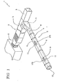
- the connecting portions 7 are for example connections for air dispensing from the transfer conduits, as illustrated in figures 1 , 2a and 2b .
- the diffuser conduits 4 are provided with a plurality of diffuser holes 8 arranged on at least an external wall of the conduit itself.
- Diffusion systems can be of a "classic" type, in which the channels are transport elements and entrusting the air diffusion quality to the terminal element.
- the channels divide the air flow according to the division of loads into the room and the diffuser thrusts the delivery air towards the ground with the aim of spreading the air delivery into the zone that it has been attributed to.
- the delivery air exiting from the holes at high velocity creates strong micro-whirls which cause a significant depression close to the perforated zone, which aspirates air by induction at rates of about 30 times above the quantity of blown air.
- the air exiting from the diffuser holes 8 creates an inductive effect on the surrounding air, leading to a mixing and a uniform diffusion internally of the use zone, with a severe drop in flow velocity at a distance of a few centimetres from the holes.
- the diffuser holes 8 are preferably organised in rows ( figures 1 and 2 show two, three or four rows of holes 8) and preferably involve all or nearly all of the longitudinal development of each diffuser conduit.
- the diffuser holes 8 can have different dimensions to one another ( figures 2a and 2b ) according to design requirements and also note that a transfer conduit can be interposed between a diffuser conduit 4 and a next connected thereto in series.
- the choice of geometric configuration of the channelling 2, i.e. the choice of connecting in series or in parallel a plurality of perforated diffuser conduits 4, of interposing transport conduit 3 between two perforated diffuser conduits 4, depends on the position of the ventilator device, the position of the use zone and the configuration thereof.
- the channelling 2 advantageously comprises at least a discharge trap door (101) defined by an access 9 and a corresponding opening system 11 of the access 9.
- the access 9 has larger dimensions that those of each diffuser hole 8 and is afforded on an external wall 10 of the channelling; the access 9 preferably has dimensions that are at least 10 times, or more, greater than the dimensions of each of the diffuser holes 8, i.e. the access 9 has an area for the outflow of air which is at least 10 times greater than the area of a diffuser hole 8.
- the opening exhibits a shape which is in plan view substantially rectangular and has dimensions such as to prevent any production of whistling or sound vibrations during the outflow of the air when the plant is in use.
- a length of between 35 and 55 mm (and preferably between 40 and 50 mm with an optimal length of 45mm) and a breadth comprised between 15 mm and 35 mm (and preferably between 20 and 30 mm with an optimal breadth of 25 mm) have been shown to be suitable.
- the opening system 11 associated to the access 9 is mobile between a plurality of stable positions comprised between a closed position of the opening and an open position thereof.
- the quantity of air unleashed into the environment in the high zone of the room can be varied.
- the plant is able correctly to diffuse air into the use zone, i.e. in such a way that the air outflow velocity from the diffuser holes 8 is just less than the "critical" velocity (i.e. the value of velocity, variable according to the situation, which leads to a user's being struck by an air flow having a residual ground-level air flow considered unpleasant).
- critical velocity i.e. the value of velocity, variable according to the situation, which leads to a user's being struck by an air flow having a residual ground-level air flow considered unpleasant.
- the outflow from the access 9 of a certain quantity of air reduces the air flow towards the diffuser holes and thus optimises the inductive effect according to requirements.
- the discharge trap door 101 operates such as to adjust the residual velocity of the air in the environment, either reducing or eliminating (according to requirements) the draughts which might be present.
- the perforated diffuser conduits 4 are made of a metal material and, for example, have a substantially hollow cylindrical form.
- the access or accesses 9 are preferably afforded on one or more perforated diffuser conduits 4.
- the perforated diffuser conduits 4 are realised in flexible material, for example a textile material.
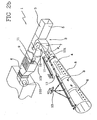
- the plant further comprises a hollow connecting element 12 for connecting up the transport channel 3 and the diffuser conduit 4 (see figure 5 ).
- the connecting element 12 has the function of stably constraining the transport conduit 2, made of a metal material, to the diffuser conduit 4, which is made of a flexible material.
- the diffuser conduit 4 can be tapered (hollow truncoconical), as shown in the figure.
- the access 9 is afforded on the connecting element 12, which is preferably located in the use zone.
- constraining means 13 are provided to constrain the perforated diffuser conduits 4, and possibly the transport conduits 3, to the ceiling of the use zone.
- the accesses 9 (which can be in any number according to design needs) are located in a channelling portion 2 that substantially faces the ceiling of the use zone.
- the air outflow from the accesses 9 is not directly aimed towards the users occupying the use zone, and in any case, should the access 9 be in proximity of the diffuser holes 8, the inductive effect created thereby recalls the air that has exited from the access 9, and re-directs it towards the use zone, thus preventing any waste of energy.
- the discharge channels can be provided with a plurality of the discharge trap doors 101 such as to enable injection of the desired quantity of air into the environment, into the zones considered to be most appropriate, thus correspondingly reducing the outflow velocity from the diffuser holes.
- the air discharged into the environment is, as explained herein above, recuperated by inductive effect thanks to the perforated diffuser conduits 4, and homogenized to the flow, thus preventing energy loss.
- the discharge trap door 101 is provided with a shutter 14 ( figures 3 and 4 ) which is slidable between the plurality of stable positions which define various discharge conditions for the air into the environment.
- the shutter 14 (sometimes known as a guillotine) is slidable between a plurality of positions which, once attained, are stably maintained.
- These positions are comprised between a position of complete closure of the access 9 and a position of almost total or maximum aperture of the access 9.
- the opening system 11 further comprises two sliding guides 15 for the shutter 14 (illustrated in a broken line in figure 3 ).
- the shutter 14 is able to slide along the two guides 15, which develop along opposite edges of the shutter 14.
- the two guides have a longitudinal development which is parallel to the sliding direction of the shutter 14.
- At least one of the two guides 15 is provided with at least an elastic element 16 for compressing the shutter 14 against an edge 17 of the access 9 and for keeping it stably in the position reached (see figure 4 ).
- the elastic elements 16 are preferably an elastic element 16 for each of the two guides 15 and they are in permanent contact with the slide 14 along respective single lines of contact.
- the elastic elements 16 are constituted by a metal band 18 which develops from a constraint portion 19 of each guide 15.
- the constraint portion 19 develops parallel to the wall 10 of the channelling portion on which the guide is constrained.
- the metal band 18 is inclined with respect to the constraint portion 19 (see figure 4 ) and comprises a first end which bears on the shutter 14, pressing it against the wall 10 of the channelling portion 2.
- a second end, opposite the first, is constrained to and is preferably in a single piece with the constraint portion 19 through a spacer band 320 ( figure 4 ).
- the guides 15 are preferably constrained to an internal surface of the wall 10 of the channelling 2 in order to arrange the shutter 14 internally of the channelling 2 in a substantially parallel position to the wall 10 of the channelling 2.
- the guides 15 are stably constrained, for example by rivets, to the internal surface of the wall 10 of the channelling 2 by means of the constraint portions 19 (see figure 4 ).
- the shutter 14 can be moved by activating means 21 which are removably engageable by a moving tool ( figure 3 ).
- the shutter 14 can be displaced, thus regulating the opening space only by using a moving tool; this prevents the shutter 14 from being accidentally moved once the plant has been set up and adjusted.
- the activating means 21 are constituted by a hole 22 made in the shutter 14 in proximity of an end zone thereof.
- the movement tool can be any tool (for example a screwdriver) destined to engage the hole 22 and to transmit a force to the shutter 14 which is directed along the guide 15.
- the invention attains the set aims.
- the plant is thus able to diffuse air into the use zone correctly, i.e. such that the outlet velocity of the air from the diffuser holes 8 is such as to guarantee residual ground-level velocity that is either not perceived or at least is not unpleasant.
- the air that has exited from the access 9 can be recuperate thanks to the inductive effect guaranteed by the diffuser holes.
- the presence of an access internally of the channel advantageously constitutes a visual inlet for inspecting the channel.
Landscapes
- Engineering & Computer Science (AREA)
- Chemical & Material Sciences (AREA)
- Combustion & Propulsion (AREA)
- Mechanical Engineering (AREA)
- General Engineering & Computer Science (AREA)
- Textile Engineering (AREA)
- Duct Arrangements (AREA)
- Motor Or Generator Cooling System (AREA)
Claims (9)
- Système de distribution d'air comprenant une canalisation (2) à travers laquelle un flux d'air est transféré par un dispositif apte à transmettre l'énergie au flux d'air au moyen d'une augmentation de pression à une zone d'utilisation, la canalisation (2) comprenant au moins un conduit de transfert (3) mis en communication de fluide avec le dispositif et au moins un conduit diffuseur (4) mis en communication de fluide avec le conduit de transfert (3) et muni d'une pluralité de trous diffuseurs (8) rangés sur au moins une paroi extérieure de celui-ci afin d'injecter l'air dans la zone d'utilisation; caractérisé en ce que la canalisation (2) comprend au moins un panneau de décharge (101) présentant un accès (9) plus grand que chaque trou diffuseur (8) rangé sur une paroi extérieure (10) de la canalisation (2) pour distribuer l'air de la canalisation vers un environnement extérieur, et en ce que il comprend un système d'ouverture (11) pour l'accès (9), lequel système d'ouverture (11) est mobile parmi une pluralité de positions fixes comprises entre une position fermée de l'accès (9) et une position d'ouverture maximale de l'accès (9).
- Système selon la revendication 1, caractérisé en ce que le conduit diffuseur (4) présente des trous diffuseurs (8) aptes à générer un effet de rappel inductif de l'air autour du diffuseur, l'accès (9) étant placé préférablement proche des trous afin de permettre la récupération de l'air en sortie par effet inductif, et l'accès (9) étant rangé plus préférablement sur le conduit diffuseur (4).
- Système selon la revendication 1, comprenant en outre un élément de liaison creux (12) pour relier le conduit de transfert (3) et le conduit diffuseur (4), l'accès (9) étant placé sur une paroi extérieure de l'élément de liaison.
- Système selon l'une quelconque des revendications précédentes, où le système d'ouverture (11) comprend un panneau ou volet (14) glissant parmi les positions progressives fixes fermées/ouvertes de l'accès (9).
- Système selon la revendication 4, où le système d'ouverture (11) comprend en outre deux guides glissants (15) pour le volet (14); au moins l'un des deux guides (15) étant muni d'au moins un élément élastique (16) pour comprimer le volet (14) contre un bord de l'accès (9) et maintenir la stabilité d'une position atteinte, l'au moins un élément élastique (16) étant préférablement en contact permanent avec le volet (14) le long de lignes de contact individuelles respectives.
- Système selon l'une quelconque des revendications précédentes, comprenant des moyens d'activation (21) pour le volet (14) aptes à déplacer le volet (14) parmi la pluralité de positions fixes; les moyens d'activation (21) étant engageables de façon amovible par un outil de déplacement apte à déplacer le volet (14).
- Système selon la revendication 5, où les guides (15) sont reliés à une surface intérieure de la paroi (10) de la canalisation (2) de sorte que le volet (14) puisse être rangé à l'intérieur de la canalisation (2) dans une position sensiblement parallèle à la paroi (10) de la canalisation (2).
- Système selon l'une quelconque des revendications précédentes, où l'accès (9) est placé dans une portion de canalisation (2) en face d'un plafond de la zone d'utilisation.
- Système selon l'une quelconque des revendications précédentes, comprenant au moins un conduit diffuseur (4) pour injecter l'air dans un environnement, générant un effet inductif, et au moins un canal de sortie de l'air pour injecter l'air dans un environnement sans perturber sensiblement un effet du conduit diffuseur (4), le conduit diffuseur (4) et le canal de sortie de l'air étant en communication de fluide avec le conduit de transfert (3), le conduit de sortie présentant un ou plusieurs des accès (9) afin d'augmenter/réduire une quantité d'air injecté dans l'environnement à travers les canaux de sortie et ainsi afin de régler une vitesse de sortie de l'air du conduit diffuseur (4).
Applications Claiming Priority (1)
| Application Number | Priority Date | Filing Date | Title |
|---|---|---|---|
| ITMI2009A000275A IT1393105B1 (it) | 2009-02-26 | 2009-02-26 | Impianto di distribuzione di aria comprendente una botola di scarico per la regolazione delle correnti di aria in ambiente |
Publications (2)
| Publication Number | Publication Date |
|---|---|
| EP2224183A1 EP2224183A1 (fr) | 2010-09-01 |
| EP2224183B1 true EP2224183B1 (fr) | 2015-05-06 |
Family
ID=41259921
Family Applications (1)
| Application Number | Title | Priority Date | Filing Date |
|---|---|---|---|
| EP20100154832 Active EP2224183B1 (fr) | 2009-02-26 | 2010-02-26 | Système de distribution d'air et conduit diffuseur pour celui-ci |
Country Status (2)
| Country | Link |
|---|---|
| EP (1) | EP2224183B1 (fr) |
| IT (1) | IT1393105B1 (fr) |
Families Citing this family (5)
| Publication number | Priority date | Publication date | Assignee | Title |
|---|---|---|---|---|
| FR3003017B1 (fr) * | 2013-03-05 | 2016-11-11 | Eric Fenioux | Gaine de ventilation pour installations destinees a des animaux et systeme de ventilation comportant ladite gaine |
| EP3054234A1 (fr) * | 2015-02-09 | 2016-08-10 | Marco Zambolin | Dispositif de traitement de l'air, procédé de traitement de l'air et l'utilisation dudit dispositif |
| FR3101937B1 (fr) | 2019-10-10 | 2021-10-22 | Ludovic Boulanger | Dispositif de ventilation de bâtiment |
| EP4071420A1 (fr) | 2021-04-08 | 2022-10-12 | Air'technologies | Conduit diffuseur pour diffuser de l'air conditionné |
| EP4269900A1 (fr) | 2022-04-28 | 2023-11-01 | Air'technologies | Conduit diffuseur pour diffuser de l'air conditionné |
Family Cites Families (4)
| Publication number | Priority date | Publication date | Assignee | Title |
|---|---|---|---|---|
| US3357088A (en) * | 1964-10-02 | 1967-12-12 | Whirlpool Co | Method of attaching a hanger to an elongated flexible tube wall |
| DK12792D0 (da) * | 1992-02-03 | 1992-02-03 | Ke Safematic As | Ventilationssystem |
| US6983889B2 (en) * | 2003-03-21 | 2006-01-10 | Home Comfort Zones, Inc. | Forced-air zone climate control system for existing residential houses |
| CA2512303A1 (fr) * | 2004-09-13 | 2006-03-13 | Nickolaj Hrebeniuk | Hublot d'inspection avec systeme d'eclairage et d'alarme facultatif |
-
2009
- 2009-02-26 IT ITMI2009A000275A patent/IT1393105B1/it active
-
2010
- 2010-02-26 EP EP20100154832 patent/EP2224183B1/fr active Active
Also Published As
| Publication number | Publication date |
|---|---|
| ITMI20090275A1 (it) | 2010-08-27 |
| IT1393105B1 (it) | 2012-04-11 |
| EP2224183A1 (fr) | 2010-09-01 |
Similar Documents
| Publication | Publication Date | Title |
|---|---|---|
| EP2224183B1 (fr) | Système de distribution d'air et conduit diffuseur pour celui-ci | |
| US10337760B2 (en) | Air diffuser and an air circulation system | |
| US20130023198A1 (en) | System and method for delivering air | |
| US9759444B2 (en) | Arrangement for ventilating a room, in particular a laboratory room | |
| US20060211365A1 (en) | Induction diffuser | |
| AU2013234030B2 (en) | Chilled beam with multiple modes | |
| CN214396748U (zh) | 具有空调系统的交通工具 | |
| US10677491B2 (en) | Air distribution device | |
| EP2394100B1 (fr) | Dispositif terminal de fourniture d'air | |
| JP5335472B2 (ja) | 冷暖房システム | |
| KR200458718Y1 (ko) | 공조장치용 고소형 가변 선회 취출구 | |
| JP4398217B2 (ja) | 吹出口装置 | |
| US10462934B2 (en) | Penthouse cooling/return air distribution assembly | |
| RU2375645C2 (ru) | Устройство для подачи воздуха | |
| RU2607546C1 (ru) | Воздухораспределитель с переменным расходом | |
| EP3343119B1 (fr) | Diffuseur d'air | |
| CN209459163U (zh) | 气流引导装置及数据中心空调系统 | |
| AU2002313921B2 (en) | Induction Diffuser | |
| JP6052959B2 (ja) | 空調システム | |
| RU172824U1 (ru) | Воздухораспределитель "генератор комфорта" | |
| DE202012101832U1 (de) | Luftdurchlassvorrichtung zur Belüftung | |
| WO2001061253A1 (fr) | Systeme d'aeration a ecoulement stabilise | |
| EP1254342B1 (fr) | Dispositif de ventilation monte sur une paroi | |
| AU2012101778A4 (en) | A system and method for delivering air | |
| JP2014020694A (ja) | 吹出装置 |
Legal Events
| Date | Code | Title | Description |
|---|---|---|---|
| PUAI | Public reference made under article 153(3) epc to a published international application that has entered the european phase |
Free format text: ORIGINAL CODE: 0009012 |
|
| AK | Designated contracting states |
Kind code of ref document: A1 Designated state(s): AT BE BG CH CY CZ DE DK EE ES FI FR GB GR HR HU IE IS IT LI LT LU LV MC MK MT NL NO PL PT RO SE SI SK SM TR |
|
| AX | Request for extension of the european patent |
Extension state: AL BA RS |
|
| 17P | Request for examination filed |
Effective date: 20110225 |
|
| 17Q | First examination report despatched |
Effective date: 20140703 |
|
| GRAP | Despatch of communication of intention to grant a patent |
Free format text: ORIGINAL CODE: EPIDOSNIGR1 |
|
| RIC1 | Information provided on ipc code assigned before grant |
Ipc: F24F 13/06 20060101ALI20150204BHEP Ipc: F24F 13/02 20060101AFI20150204BHEP Ipc: F24F 13/068 20060101ALI20150204BHEP |
|
| INTG | Intention to grant announced |
Effective date: 20150305 |
|
| GRAS | Grant fee paid |
Free format text: ORIGINAL CODE: EPIDOSNIGR3 |
|
| GRAA | (expected) grant |
Free format text: ORIGINAL CODE: 0009210 |
|
| AK | Designated contracting states |
Kind code of ref document: B1 Designated state(s): AT BE BG CH CY CZ DE DK EE ES FI FR GB GR HR HU IE IS IT LI LT LU LV MC MK MT NL NO PL PT RO SE SI SK SM TR |
|
| REG | Reference to a national code |
Ref country code: GB Ref legal event code: FG4D |
|
| REG | Reference to a national code |
Ref country code: CH Ref legal event code: EP |
|
| REG | Reference to a national code |
Ref country code: IE Ref legal event code: FG4D |
|
| REG | Reference to a national code |
Ref country code: AT Ref legal event code: REF Ref document number: 725986 Country of ref document: AT Kind code of ref document: T Effective date: 20150615 |
|
| REG | Reference to a national code |
Ref country code: DE Ref legal event code: R096 Ref document number: 602010024419 Country of ref document: DE Effective date: 20150618 |
|
| REG | Reference to a national code |
Ref country code: CH Ref legal event code: NV Representative=s name: ING. ALESSANDRO GALASSI C/O PGA SRL, MILANO, S, CH |
|
| REG | Reference to a national code |
Ref country code: NL Ref legal event code: T3 |
|
| REG | Reference to a national code |
Ref country code: AT Ref legal event code: MK05 Ref document number: 725986 Country of ref document: AT Kind code of ref document: T Effective date: 20150506 |
|
| REG | Reference to a national code |
Ref country code: LT Ref legal event code: MG4D |
|
| PG25 | Lapsed in a contracting state [announced via postgrant information from national office to epo] |
Ref country code: PT Free format text: LAPSE BECAUSE OF FAILURE TO SUBMIT A TRANSLATION OF THE DESCRIPTION OR TO PAY THE FEE WITHIN THE PRESCRIBED TIME-LIMIT Effective date: 20150907 Ref country code: LT Free format text: LAPSE BECAUSE OF FAILURE TO SUBMIT A TRANSLATION OF THE DESCRIPTION OR TO PAY THE FEE WITHIN THE PRESCRIBED TIME-LIMIT Effective date: 20150506 Ref country code: NO Free format text: LAPSE BECAUSE OF FAILURE TO SUBMIT A TRANSLATION OF THE DESCRIPTION OR TO PAY THE FEE WITHIN THE PRESCRIBED TIME-LIMIT Effective date: 20150806 Ref country code: HR Free format text: LAPSE BECAUSE OF FAILURE TO SUBMIT A TRANSLATION OF THE DESCRIPTION OR TO PAY THE FEE WITHIN THE PRESCRIBED TIME-LIMIT Effective date: 20150506 Ref country code: FI Free format text: LAPSE BECAUSE OF FAILURE TO SUBMIT A TRANSLATION OF THE DESCRIPTION OR TO PAY THE FEE WITHIN THE PRESCRIBED TIME-LIMIT Effective date: 20150506 Ref country code: ES Free format text: LAPSE BECAUSE OF FAILURE TO SUBMIT A TRANSLATION OF THE DESCRIPTION OR TO PAY THE FEE WITHIN THE PRESCRIBED TIME-LIMIT Effective date: 20150506 |
|
| PG25 | Lapsed in a contracting state [announced via postgrant information from national office to epo] |
Ref country code: IS Free format text: LAPSE BECAUSE OF FAILURE TO SUBMIT A TRANSLATION OF THE DESCRIPTION OR TO PAY THE FEE WITHIN THE PRESCRIBED TIME-LIMIT Effective date: 20150906 Ref country code: BG Free format text: LAPSE BECAUSE OF FAILURE TO SUBMIT A TRANSLATION OF THE DESCRIPTION OR TO PAY THE FEE WITHIN THE PRESCRIBED TIME-LIMIT Effective date: 20150806 Ref country code: AT Free format text: LAPSE BECAUSE OF FAILURE TO SUBMIT A TRANSLATION OF THE DESCRIPTION OR TO PAY THE FEE WITHIN THE PRESCRIBED TIME-LIMIT Effective date: 20150506 Ref country code: LV Free format text: LAPSE BECAUSE OF FAILURE TO SUBMIT A TRANSLATION OF THE DESCRIPTION OR TO PAY THE FEE WITHIN THE PRESCRIBED TIME-LIMIT Effective date: 20150506 Ref country code: GR Free format text: LAPSE BECAUSE OF FAILURE TO SUBMIT A TRANSLATION OF THE DESCRIPTION OR TO PAY THE FEE WITHIN THE PRESCRIBED TIME-LIMIT Effective date: 20150807 |
|
| PG25 | Lapsed in a contracting state [announced via postgrant information from national office to epo] |
Ref country code: EE Free format text: LAPSE BECAUSE OF FAILURE TO SUBMIT A TRANSLATION OF THE DESCRIPTION OR TO PAY THE FEE WITHIN THE PRESCRIBED TIME-LIMIT Effective date: 20150506 Ref country code: DK Free format text: LAPSE BECAUSE OF FAILURE TO SUBMIT A TRANSLATION OF THE DESCRIPTION OR TO PAY THE FEE WITHIN THE PRESCRIBED TIME-LIMIT Effective date: 20150506 |
|
| REG | Reference to a national code |
Ref country code: FR Ref legal event code: PLFP Year of fee payment: 7 |
|
| REG | Reference to a national code |
Ref country code: DE Ref legal event code: R097 Ref document number: 602010024419 Country of ref document: DE |
|
| PG25 | Lapsed in a contracting state [announced via postgrant information from national office to epo] |
Ref country code: CZ Free format text: LAPSE BECAUSE OF FAILURE TO SUBMIT A TRANSLATION OF THE DESCRIPTION OR TO PAY THE FEE WITHIN THE PRESCRIBED TIME-LIMIT Effective date: 20150506 Ref country code: RO Free format text: LAPSE BECAUSE OF NON-PAYMENT OF DUE FEES Effective date: 20150506 Ref country code: PL Free format text: LAPSE BECAUSE OF FAILURE TO SUBMIT A TRANSLATION OF THE DESCRIPTION OR TO PAY THE FEE WITHIN THE PRESCRIBED TIME-LIMIT Effective date: 20150506 Ref country code: SK Free format text: LAPSE BECAUSE OF FAILURE TO SUBMIT A TRANSLATION OF THE DESCRIPTION OR TO PAY THE FEE WITHIN THE PRESCRIBED TIME-LIMIT Effective date: 20150506 |
|
| PLBE | No opposition filed within time limit |
Free format text: ORIGINAL CODE: 0009261 |
|
| STAA | Information on the status of an ep patent application or granted ep patent |
Free format text: STATUS: NO OPPOSITION FILED WITHIN TIME LIMIT |
|
| 26N | No opposition filed |
Effective date: 20160209 |
|
| PG25 | Lapsed in a contracting state [announced via postgrant information from national office to epo] |
Ref country code: SI Free format text: LAPSE BECAUSE OF FAILURE TO SUBMIT A TRANSLATION OF THE DESCRIPTION OR TO PAY THE FEE WITHIN THE PRESCRIBED TIME-LIMIT Effective date: 20150506 |
|
| PG25 | Lapsed in a contracting state [announced via postgrant information from national office to epo] |
Ref country code: MC Free format text: LAPSE BECAUSE OF FAILURE TO SUBMIT A TRANSLATION OF THE DESCRIPTION OR TO PAY THE FEE WITHIN THE PRESCRIBED TIME-LIMIT Effective date: 20150506 |
|
| GBPC | Gb: european patent ceased through non-payment of renewal fee |
Effective date: 20160226 |
|
| REG | Reference to a national code |
Ref country code: CH Ref legal event code: PFA Owner name: ZAMBOLIN, MARCO, IT Free format text: FORMER OWNER: ZAMBOLIN, MARCO, IT Ref country code: IE Ref legal event code: MM4A |
|
| REG | Reference to a national code |
Ref country code: FR Ref legal event code: PLFP Year of fee payment: 8 |
|
| PG25 | Lapsed in a contracting state [announced via postgrant information from national office to epo] |
Ref country code: IE Free format text: LAPSE BECAUSE OF NON-PAYMENT OF DUE FEES Effective date: 20160226 Ref country code: GB Free format text: LAPSE BECAUSE OF NON-PAYMENT OF DUE FEES Effective date: 20160226 |
|
| PG25 | Lapsed in a contracting state [announced via postgrant information from national office to epo] |
Ref country code: SE Free format text: LAPSE BECAUSE OF FAILURE TO SUBMIT A TRANSLATION OF THE DESCRIPTION OR TO PAY THE FEE WITHIN THE PRESCRIBED TIME-LIMIT Effective date: 20150506 |
|
| PG25 | Lapsed in a contracting state [announced via postgrant information from national office to epo] |
Ref country code: MT Free format text: LAPSE BECAUSE OF FAILURE TO SUBMIT A TRANSLATION OF THE DESCRIPTION OR TO PAY THE FEE WITHIN THE PRESCRIBED TIME-LIMIT Effective date: 20150506 |
|
| REG | Reference to a national code |
Ref country code: FR Ref legal event code: PLFP Year of fee payment: 9 |
|
| PGFP | Annual fee paid to national office [announced via postgrant information from national office to epo] |
Ref country code: CH Payment date: 20180213 Year of fee payment: 9 Ref country code: DE Payment date: 20180214 Year of fee payment: 9 |
|
| PG25 | Lapsed in a contracting state [announced via postgrant information from national office to epo] |
Ref country code: SM Free format text: LAPSE BECAUSE OF FAILURE TO SUBMIT A TRANSLATION OF THE DESCRIPTION OR TO PAY THE FEE WITHIN THE PRESCRIBED TIME-LIMIT Effective date: 20150506 Ref country code: CY Free format text: LAPSE BECAUSE OF FAILURE TO SUBMIT A TRANSLATION OF THE DESCRIPTION OR TO PAY THE FEE WITHIN THE PRESCRIBED TIME-LIMIT Effective date: 20150506 Ref country code: HU Free format text: LAPSE BECAUSE OF FAILURE TO SUBMIT A TRANSLATION OF THE DESCRIPTION OR TO PAY THE FEE WITHIN THE PRESCRIBED TIME-LIMIT; INVALID AB INITIO Effective date: 20100226 |
|
| PG25 | Lapsed in a contracting state [announced via postgrant information from national office to epo] |
Ref country code: TR Free format text: LAPSE BECAUSE OF FAILURE TO SUBMIT A TRANSLATION OF THE DESCRIPTION OR TO PAY THE FEE WITHIN THE PRESCRIBED TIME-LIMIT Effective date: 20150506 Ref country code: MK Free format text: LAPSE BECAUSE OF FAILURE TO SUBMIT A TRANSLATION OF THE DESCRIPTION OR TO PAY THE FEE WITHIN THE PRESCRIBED TIME-LIMIT Effective date: 20150506 Ref country code: MT Free format text: LAPSE BECAUSE OF FAILURE TO SUBMIT A TRANSLATION OF THE DESCRIPTION OR TO PAY THE FEE WITHIN THE PRESCRIBED TIME-LIMIT Effective date: 20160229 |
|
| REG | Reference to a national code |
Ref country code: DE Ref legal event code: R119 Ref document number: 602010024419 Country of ref document: DE |
|
| REG | Reference to a national code |
Ref country code: CH Ref legal event code: PL |
|
| PG25 | Lapsed in a contracting state [announced via postgrant information from national office to epo] |
Ref country code: LI Free format text: LAPSE BECAUSE OF NON-PAYMENT OF DUE FEES Effective date: 20190228 Ref country code: CH Free format text: LAPSE BECAUSE OF NON-PAYMENT OF DUE FEES Effective date: 20190228 |
|
| PG25 | Lapsed in a contracting state [announced via postgrant information from national office to epo] |
Ref country code: DE Free format text: LAPSE BECAUSE OF NON-PAYMENT OF DUE FEES Effective date: 20190903 |
|
| PGFP | Annual fee paid to national office [announced via postgrant information from national office to epo] |
Ref country code: NL Payment date: 20220224 Year of fee payment: 13 |
|
| PGFP | Annual fee paid to national office [announced via postgrant information from national office to epo] |
Ref country code: LU Payment date: 20230222 Year of fee payment: 14 Ref country code: FR Payment date: 20230223 Year of fee payment: 14 |
|
| PGFP | Annual fee paid to national office [announced via postgrant information from national office to epo] |
Ref country code: IT Payment date: 20230220 Year of fee payment: 14 Ref country code: BE Payment date: 20230222 Year of fee payment: 14 |
|
| REG | Reference to a national code |
Ref country code: NL Ref legal event code: MM Effective date: 20230301 |
|
| PG25 | Lapsed in a contracting state [announced via postgrant information from national office to epo] |
Ref country code: NL Free format text: LAPSE BECAUSE OF NON-PAYMENT OF DUE FEES Effective date: 20230301 |