EP2224099A2 - Laufspalteinstellungssystem einer Fluggasturbine - Google Patents
Laufspalteinstellungssystem einer Fluggasturbine Download PDFInfo
- Publication number
- EP2224099A2 EP2224099A2 EP10001140A EP10001140A EP2224099A2 EP 2224099 A2 EP2224099 A2 EP 2224099A2 EP 10001140 A EP10001140 A EP 10001140A EP 10001140 A EP10001140 A EP 10001140A EP 2224099 A2 EP2224099 A2 EP 2224099A2
- Authority
- EP
- European Patent Office
- Prior art keywords
- air
- cooling air
- core engine
- bypass
- cooling
- Prior art date
- Legal status (The legal status is an assumption and is not a legal conclusion. Google has not performed a legal analysis and makes no representation as to the accuracy of the status listed.)
- Granted
Links
- 238000001816 cooling Methods 0.000 claims abstract description 35
- 238000009423 ventilation Methods 0.000 claims abstract description 9
- 230000002349 favourable effect Effects 0.000 description 2
- 238000000034 method Methods 0.000 description 2
- 238000009827 uniform distribution Methods 0.000 description 2
- 238000005273 aeration Methods 0.000 description 1
- 230000001914 calming effect Effects 0.000 description 1
- 239000002826 coolant Substances 0.000 description 1
- 230000001419 dependent effect Effects 0.000 description 1
- 238000010586 diagram Methods 0.000 description 1
- 238000009826 distribution Methods 0.000 description 1
- 230000000694 effects Effects 0.000 description 1
- 230000007613 environmental effect Effects 0.000 description 1
- 239000000446 fuel Substances 0.000 description 1
- 238000005457 optimization Methods 0.000 description 1
- 230000003068 static effect Effects 0.000 description 1
- 239000000725 suspension Substances 0.000 description 1
- 238000005494 tarnishing Methods 0.000 description 1
- 238000011144 upstream manufacturing Methods 0.000 description 1
Images

Classifications
-
- F—MECHANICAL ENGINEERING; LIGHTING; HEATING; WEAPONS; BLASTING
- F01—MACHINES OR ENGINES IN GENERAL; ENGINE PLANTS IN GENERAL; STEAM ENGINES
- F01D—NON-POSITIVE DISPLACEMENT MACHINES OR ENGINES, e.g. STEAM TURBINES
- F01D11/00—Preventing or minimising internal leakage of working-fluid, e.g. between stages
- F01D11/08—Preventing or minimising internal leakage of working-fluid, e.g. between stages for sealing space between rotor blade tips and stator
- F01D11/14—Adjusting or regulating tip-clearance, i.e. distance between rotor-blade tips and stator casing
- F01D11/20—Actively adjusting tip-clearance
- F01D11/24—Actively adjusting tip-clearance by selectively cooling-heating stator or rotor components
-
- F—MECHANICAL ENGINEERING; LIGHTING; HEATING; WEAPONS; BLASTING
- F02—COMBUSTION ENGINES; HOT-GAS OR COMBUSTION-PRODUCT ENGINE PLANTS
- F02K—JET-PROPULSION PLANTS
- F02K3/00—Plants including a gas turbine driving a compressor or a ducted fan
- F02K3/02—Plants including a gas turbine driving a compressor or a ducted fan in which part of the working fluid by-passes the turbine and combustion chamber
- F02K3/04—Plants including a gas turbine driving a compressor or a ducted fan in which part of the working fluid by-passes the turbine and combustion chamber the plant including ducted fans, i.e. fans with high volume, low pressure outputs, for augmenting the jet thrust, e.g. of double-flow type
- F02K3/06—Plants including a gas turbine driving a compressor or a ducted fan in which part of the working fluid by-passes the turbine and combustion chamber the plant including ducted fans, i.e. fans with high volume, low pressure outputs, for augmenting the jet thrust, e.g. of double-flow type with front fan
-
- B—PERFORMING OPERATIONS; TRANSPORTING
- B64—AIRCRAFT; AVIATION; COSMONAUTICS
- B64D—EQUIPMENT FOR FITTING IN OR TO AIRCRAFT; FLIGHT SUITS; PARACHUTES; ARRANGEMENT OR MOUNTING OF POWER PLANTS OR PROPULSION TRANSMISSIONS IN AIRCRAFT
- B64D33/00—Arrangements in aircraft of power plant parts or auxiliaries not otherwise provided for
- B64D33/02—Arrangements in aircraft of power plant parts or auxiliaries not otherwise provided for of combustion air intakes
- B64D2033/024—Arrangements in aircraft of power plant parts or auxiliaries not otherwise provided for of combustion air intakes comprising cooling means
-
- F—MECHANICAL ENGINEERING; LIGHTING; HEATING; WEAPONS; BLASTING
- F05—INDEXING SCHEMES RELATING TO ENGINES OR PUMPS IN VARIOUS SUBCLASSES OF CLASSES F01-F04
- F05D—INDEXING SCHEME FOR ASPECTS RELATING TO NON-POSITIVE-DISPLACEMENT MACHINES OR ENGINES, GAS-TURBINES OR JET-PROPULSION PLANTS
- F05D2260/00—Function
- F05D2260/20—Heat transfer, e.g. cooling
- F05D2260/205—Cooling fluid recirculation, i.e. after cooling one or more components is the cooling fluid recovered and used elsewhere for other purposes
-
- Y—GENERAL TAGGING OF NEW TECHNOLOGICAL DEVELOPMENTS; GENERAL TAGGING OF CROSS-SECTIONAL TECHNOLOGIES SPANNING OVER SEVERAL SECTIONS OF THE IPC; TECHNICAL SUBJECTS COVERED BY FORMER USPC CROSS-REFERENCE ART COLLECTIONS [XRACs] AND DIGESTS
- Y02—TECHNOLOGIES OR APPLICATIONS FOR MITIGATION OR ADAPTATION AGAINST CLIMATE CHANGE
- Y02T—CLIMATE CHANGE MITIGATION TECHNOLOGIES RELATED TO TRANSPORTATION
- Y02T50/00—Aeronautics or air transport
- Y02T50/60—Efficient propulsion technologies, e.g. for aircraft
Definitions
- the invention relates to a tread adjustment system of an aircraft gas turbine engine having a core engine comprising a turbine whose blade rows to the turbine housing having a nip, wherein the turbine housing is enclosed by a core engine ventilation space, which is enclosed by a lining of the core engine, wherein the panel is an inner wall a bypass channel forms.
- ATCC Active Air gap Adjustance Control System
- the prior art uses air as a cooling medium for such active systems.
- the airflow is taken from the engine bypass, which is compressed by a fan.
- the invention has for its object to provide a running gap adjustment system of an aircraft gas turbine of the type mentioned, which is particularly effective in a simple structure and simple, cost-effective implementation in terms of overall energy balance.
- air is introduced from a secondary flow in the bypass duct by means of a control system via at least one inlet port into the core engine ventilation space and that the air is subsequently recycled into the secondary flow.
- the system according to the invention is characterized by a number of significant advantages.
- the main advantage is that the cooling air is available after passing through the one or more cooling air manifold through the return line in the tributary flow for the engine thrust. If, for example, in a conventional engine, 0.7% of the air is removed from the secondary flow and not, as in the prior art, derived unused, but is subsequently used for the thrust, so there is a significant increase in performance of the engine.
- the running gap adjustment system according to the invention is thus highly effective for the energy balance of the overall process.
- the air can be introduced into at least one air distributor, which is arranged adjacent to the housing. It is particularly advantageous if the flow losses occurring here and energy losses of the cooling air are minimized.
- Cooling air is preferably supplied from the core engine ventilation space through at least one aerodynamic fairing of a connecting element of the core engine with its suspension system of an outlet nozzle opening into the secondary flow. This results in a particularly effective return of the cooling air.
- the control system preferably comprises a control valve, which is controlled by a motor control. In this way, an optimal adjustment of the cooling air flow is possible.
- a secondary flow 3 flows through a bypass duct 1, which is delimited radially inwards by a lining 2 of a core engine.
- At least one aerodynamic casing 16 is arranged, whose cross section in Fig. 1 is shown tilted by 90 ° and serves for the aerodynamic lining of the connections and lines between the core engine and nacelle. Apart from the outlet opening 17, these embodiments belong to the prior art, so that a detailed description can be dispensed with at this point.
- an inlet port 5 is shown, which forms an air inlet to the active tread adjustment system.
- the entering through the inlet port 5 air flow 4 is thus directed radially inward and enters a branching channel of a direct, unregulated cooling air duct 9 and to a control valve. 6
- the control valve 6 can be actuated via a motor 10, which can be controlled via a controller 11.
- the cooling air subsequently passes into a cooling air distributor 7, which is arranged adjacent to the turbine housing 12, so that the cooling air can hit the wall of a turbine housing 12 by impact cooling nozzles or a perforation 8. As a result, the cooling and the gap control 13 takes place.
- the arrangement described above, in particular the cooling air distributor 7, is located in a core engine ventilation space 15.
- the working pressure gradient of the described tread adjustment system results from the total pressure at the inlet of the inlet nozzle 5 minus the static pressure at the outlet nozzle 17.
- the air is thus taken from the bypass duct 3 through the air inlets 4, 5.
- the number of these air inlets can be varied on the circumference. Particularly favorable is a uniform distribution on the circumference, as in Fig. 2 is shown.
- the cooling air distributor 7 provides according to the invention for a calming of the flow and a uniform distribution of the air in the circumferential direction, so that they evenly exits through the impingement cooling nozzles 8 and impinges on the turbine housing 12 to be cooled.
- the impingement cooling effect achieves high heat transfer values and a large temperature reduction of the turbine housing 12, thereby minimizing the clearance gap 13.
- the air is conducted along the housing for convective cooling, before it then flows into the core engine ventilation space 15 and from there, as described, is fed into the secondary flow 3 via the cooling air outlet nozzles 17.
- the cooling flow returned from the outlet nozzle 17 upstream of an engine nozzle (not shown) in the secondary flow still performs a complete work for the thrust of the aircraft gas turbine.
- it is possible to achieve optimization of the system for maximum efficiency and turbine efficiency increase without risk of tarnishing by suitable control of the active tread adjustment system by the control of the aircraft gas turbine (EEC).
- the tread adjustment system of the present invention may be controlled or optimized by changing the pressure, changing the flow area, or a combination of both.
Landscapes
- Engineering & Computer Science (AREA)
- Mechanical Engineering (AREA)
- General Engineering & Computer Science (AREA)
- Chemical & Material Sciences (AREA)
- Combustion & Propulsion (AREA)
- Turbine Rotor Nozzle Sealing (AREA)
Abstract
Description
- Die Erfindung bezieht sich auf ein Laufspalteinstellungssystem einer Fluggasturbine mit einem Kerntriebwerk, welches eine Turbine umfasst, deren Schaufelreihen zum Turbinengehäuse einen Laufspalt aufweisen, wobei das Turbinengehäuse von einem Kerntriebwerklüftungsraum umschlossen wird, welcher von einer Verkleidung des Kerntriebwerks umschlossen ist, wobei die Verkleidung eine innere Wandung eines Nebenstromkanals bildet.
- Zum Stand der Technik werden die
US 2007/0140838 A1 und dieUS 2007/0140839 A1 genannt. - Aus dem Stand der Technik ist es bekannt, Systeme zur aktiven Laufspalteinstellung von Fluggasturbinen zu verwenden. Diese werden als ATCC (Activ Tip Clearance Control System) bezeichnet. Dabei wird durch äußere Kühlung des Turbinengehäuses der Laufspalt zwischen den Belägen an der radial inneren Oberfläche des Turbinengehäuses und den Turbinenrotorschaufelspitzen beeinflusst. Hierdurch werden thermische Ausdehnungen des Turbinengehäuses ebenso berücksichtigt, wie radiale Ausdehnungen der Turbinenrotoren- und Schaufeln.
- Der Stand der Technik setzt für derartige aktive Systeme Luft als Kühlmedium ein. Der Luftstrom wird aus dem Triebwerksnebenstrom entnommen, welcher durch einen Bläser komprimiert wird.
- Bei diesen Systemen ergibt sich unter nahezu allen Betriebsbedingungen ein Durchströmdruckgefälle von mindestens einem halben bar gegenüber der Umgebung. Die Systeme entnehmen die für den Schub wertvolle Luft aus dem Triebwerksnebenstrom und entsorgen diese, nachdem sie durch die Kühlluftverteiler geströmt ist, zur Umgebung der Triebwerksgondel. Somit wird die zur Kühlung verwendete Luft ungenutzt in die Umgebung abgeleitet. Dies bedeutet einen nicht unerheblichen Energieverlust und ist damit auch umweltbelastend.
- Andere aus dem Stand der Technik bekannte Systeme entnehmen die Kühlluft aus dem Verdichter. Dies führt jedoch zu einer noch schlechteren Energiebilanz des Gesamtprozesses.
- Der Erfindung liegt die Aufgabe zugrunde, ein Laufspalteinstellungssystem einer Fluggasturbine der eingangs genannten Art zu schaffen, welches bei einfachem Aufbau und einfacher, kostengünstiger Implementierung hinsichtlich der Gesamtenergiebilanz besonders wirksam ist.
- Erfindungsgemäß wird die Aufgabe durch die Merkmalskombination des Anspruchs 1 gelöst, die Unteransprüche zeigen weitere vorteilhafte Ausgestaltungen der Erfindung.
- Erfindungsgemäß ist somit vorgesehen, dass Luft aus einer Nebenströmung in dem Nebenstromkanal mittels eines Regelsystems über zumindest einen Einlassstutzen in den Kerntriebwerkslüftungsraum eingeleitet wird und dass die Luft nachfolgend in die Nebenströmung rückgeführt wird.
- Das erfindungsgemäße System zeichnet sich durch eine Reihe erheblicher Vorteile aus. Der wesentliche Vorteil liegt darin, dass die Kühlluft nach der Durchströmung des einen oder der mehreren Kühlluftverteiler durch die Rückleitung in die Nebenströmung für den Triebwerksschub zur Verfügung steht. Wenn beispielsweise bei einem üblichen Triebwerk 0,7 % der Luft aus der Nebenströmung abgeführt wird und nicht, wie beim Stand der Technik, ungenutzt abgeleitet, sondern nachfolgend für den Schub verwendet wird, so ergibt sich eine erhebliche Leistungssteigerung des Triebwerks. Das erfindungsgemäße Laufspalteinstellungssystem ist somit für die Energiebilanz des Gesamtprozesses in höchstem Maße wirkungsvoll.
- Erfindungsgemäß ist es besonders günstig, wenn die Luft in zumindest einen Luftverteiler, welcher angrenzend an das Gehäuse angeordnet ist, einleitbar ist. Dabei ist es besonders günstig, wenn die hierbei auftretenden Strömungsverluste und Energieverluste der Kühlluft minimiert werden.
- Kühlluft wird bevorzugterweise von dem Kerntriebwerklüftungsraum durch zumindest eine aerodynamische Verkleidung eines Verbindungselements des Kerntriebwerks mit dessen Aufhängungssystem einer in die Nebenströmung mündenden Auslassdüse zugeführt. Hierdurch erfolgt eine besonders wirkungsvolle Rückführung der Kühlluft.
- Das Regelsystem umfasst bevorzugterweise ein Regelventil, welches motorisch über eine Steuerung steuerbar ist. Auf diese Weise ist eine optimale Anpassung des Kühlluftstroms möglich.
- Im Folgenden wird die Erfindung anhand eines Ausführungsbeispiels in Verbindung mit der Zeichnung beschrieben. Dabei zeigt:
- Fig. 1
- eine schematische Axial-Teilschnittansicht eines erfindungsgemäßen Ausführungsbeispiels des Laufspalteinstellungssystems,
- Fig. 2
- eine Radial-Schnittansicht gemäß
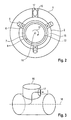
Fig. 1 , und - Fig. 3
- eine perspektivische Prinzipskizze der Ausleitung der Luft durch eine Auslassdüse in die Nebenströmung.
- Erfindungsgemäß durchströmt eine Nebenströmung 3 einen Nebenstromkanal 1, der radial nach innen durch eine Verkleidung 2 eines Kerntriebwerks begrenzt wird.
- In dem Nebenstromkanal 1 ist zumindest eine aerodynamische Verkleidung 16 angeordnet, deren Querschnitt in
Fig. 1 um 90° gekippt dargestellt ist und zur aerodynamischen Verkleidung der Verbindungen und Leitungen zwischen Kerntriebwerk und Gondel dient. Diese Ausgestaltungen gehören abgesehen von der Auslassöffnung 17 zum Stand der Technik, so dass auf eine detaillierte Beschreibung an dieser Stelle verzichtet werden kann. - In dem Nebenstromkanal 1 ist ein Einlassstutzen 5 dargestellt, welcher einen Lufteinlass zum aktiven Laufspalteinstellungssystem bildet. Die durch den Einlassstutzen 5 eintretende Luftströmung 4 wird somit radial nach innen geleitet und gelangt in einen abzweigenden Kanal einer direkten, ungeregelten Kühlluftführung 9 und zu einem Regelventil 6.
- Das Regelventil 6 ist über einen Motor 10 betätigbar, welcher über eine Steuerung 11 ansteuerbar ist.
- Die Kühlluft gelangt nachfolgend in einen Kühlluftverteiler 7, welcher angrenzend an das Turbinengehäuse 12 angeordnet ist, so dass die Kühlluft durch Prallkühldüsen oder eine Lochung 8 auf die Wandung eines Turbinengehäuses 12 auftreffen kann. Hierdurch erfolgt die Kühlung und die Spaltregelung 13.
- Radial innenliegend zeigt die
Fig. 1 Turbinenradschaufelspitzen 14. - Die oben beschriebene Anordnung, insbesondere der Kühlluftverteiler 7, befindet sich in einem Kerntriebwerklüftungsraum 15.
- Aus dem Kerntriebwerklüftungsraum 15 gelangt die Luft in den Innenraum der aerodynamischen Verkleidung, so wie dies in
Fig. 3 schematisch dargestellt ist und strömt über eine Auslassdüse 17 in den Nebenstromkanal 1. - Das Arbeitsdruckgefälle des beschriebenen Laufspalteinstellungssystems ergibt sich durch den Gesamtdruck am Einlauf des Einlassstutzens 5 minus dem statischen Druck an der Auslassdüse 17.
- Erfindungsgemäß wird die Luft somit dem Nebenstromkanal 3 durch die Lufteinlässe 4, 5 entnommen. Die Anzahl dieser Lufteinlässe (Einlassstutzen 5 mit Lufteinlass 4) kann am Umfang variiert werden. Besonders günstig ist dabei eine gleichmäßige Verteilung am Umfang, so wie dies in
Fig. 2 gezeigt ist. - Alternativ zu der Regelung der Kühlung mittels des Regelventils 6 ist es erfindungsgemäß auch möglich, die Anzahl der Prallkühldüsen 8 zu variieren.
- Der Kühlluftverteiler 7 sorgt erfindungsgemäß für eine Beruhigung der Strömung und eine gleichmäßige Verteilung der Luft in Umfangsrichtung, damit diese gleichmäßig durch die Prallkühldüsen 8 austritt und auf das zu kühlende Turbinengehäuse 12 auftrifft.
- Durch den Prallkühlungseffekt werden hohe Wärmeübergangswerte und eine große Temperaturreduktion des Turbinengehäuses 12 erreicht, wodurch der Laufspalt 13 minimiert wird.
- Im weiteren Verlauf wird die Luft zur konvektiven Kühlung entlang des Gehäuses geführt, bevor sie dann in den Kerntriebwerklüftungsraum 15 strömt und von dort, wie beschrieben, in den Nebenstrom 3 über die Kühlluftauslassdüsen 17 zugeführt wird.
- Erfindungsgemäß ist es möglich, durch geeignete aerodynamische Auslegung die Druckverluste entlang der einzelnen Komponenten des erfindungsgemäßen Systems zu minimieren, so dass das System mit einem kleinen Druckgefälle arbeiten kann, welches nur 1/10 eines aus dem Stand der Technik bekannten Hochdrucksystems entspricht.
- Erfindungsgemäß leistet die von der Auslassdüse 17 stromauf einer nicht dargestellten Triebwerksdüse im Nebenstrom zurückgeleitete Kühlströmung noch vollständige Arbeit für den Schub der Fluggasturbine. Erfindungsgemäß ist es möglich, durch eine geeignete Steuerung des aktiven Laufspalteinstellungssystems durch die Steuerung der Fluggasturbine (EEC) eine Optimierung des Systems für eine maximale Effizienz und eine Turbinenwirkungsgraderhöhung ohne Anstreifgefahr zu erreichen.
- Das erfindungsgemäße Laufspalteinstellungssystem kann durch eine Änderung des Drucks, durch eine Änderung der Durchströmfläche oder durch eine Kombination aus beidem geregelt bzw. optimiert werden.
- Insgesamt ergibt sich somit durch die günstige Gesamt-Energiebilanz eine Reduzierung des Kraftstoffverbrauchs. Weiterhin ist es möglich, die Kosten zu reduzieren und das Systemgewicht zu senken. Zusätzlich führt die erfindungsgemäße Kühlung zu einer Erhöhung der Triebwerkszuverlässigkeit sowie zu einer positiven Umweltbilanz.
-
- 1
- Nebenstromkanal
- 2
- Verkleidung des Kerntriebwerks
- 3
- Strömungsrichtung im Nebenstromkanal
- 4
- Lufteinlass zum ATCC System
- 5
- Einlassstutzen
- 6
- Regelventil
- 7
- Kühlluftverteiler
- 8
- Prallkühldüsen/Lochung
- 9
- Direkte, ungeregelte Kühlluftführung
- 10
- Motor zur Ventilbetätigung
- 11
- Steuerungsblock (durch die EEC) / Steuerung
- 12
- Turbinengehäuse
- 13
- Spalt (Regelungsziel) / Laufspalt
- 14
- Turbinenradschaufelspitzen
- 15
- Kerntrieblüftungsraum (Zone 2)
- 16
- Aerodynamische Verkleidung der Verbindungen zum Kerntriebwerk
- 17
- ATCC Kühlluftauslassdüse im Nebenstromkanal / Auslassdüse
- 18
- Maschinenachse
Claims (5)
- Laufspalteinstellungssystem einer Fluggasturbine mit einem Kerntriebwerk, welches eine Turbine umfasst, deren Schaufelreihen zum Turbinengehäuse (12) einen Laufspalt (13) aufweisen, wobei das Turbinengehäuse (12) von einem Kerntriebwerklüftungsraum (15) umschlossen wird, welcher von einer Verkleidung (2) des Kerntriebwerks umschlossen ist, wobei die Verkleidung (2) eine innere Wandung eines Nebenstromkanals (1) bildet, dadurch gekennzeichnet, dass Luft aus dem Nebenstromkanal (1) mittels eines Regelsystems (6, 10, 11) über zumindest einen Einlassstutzen (5) in einen Kühlluftverteiler (7) einleitbar ist und dass die Luft nachfolgend in die Nebenströmung (3) zurückgeführt wird.
- System nach Anspruch 1, dadurch gekennzeichnet, dass Luft in zumindest einen Luftverteiler (7), welcher angrenzend an das Turbinengehäuse (12) zur Regelung des Laufspalts (13) angeordnet ist, einleitbar ist.
- System nach Anspruch 1 oder 2, dadurch gekennzeichnet, dass Luft vom Kerntriebwerklüftungsraum (15) durch zumindest eine aerodynamische Verkleidung (16) der Anbauteile und Leitungen einer in die Nebenströmung mündenden Auslassdüse (17) zuführbar ist.
- System nach einem der Ansprüche 1 bis 3, dadurch gekennzeichnet, dass das Regelsystem zumindest ein Regelventil (6) umfasst, welches mittels eines Motors (10) über eine Steuerung (11) betätigbar ist.
- System nach einem der Ansprüche 1 bis 4, dadurch gekennzeichnet, dass in Axialrichtung mehrere Kühlluftverteiler (7) vorgesehen sind.
Applications Claiming Priority (1)
| Application Number | Priority Date | Filing Date | Title |
|---|---|---|---|
| DE102009010647A DE102009010647A1 (de) | 2009-02-26 | 2009-02-26 | Laufspalteinstellungssystem einer Fluggasturbine |
Publications (3)
| Publication Number | Publication Date |
|---|---|
| EP2224099A2 true EP2224099A2 (de) | 2010-09-01 |
| EP2224099A3 EP2224099A3 (de) | 2013-02-27 |
| EP2224099B1 EP2224099B1 (de) | 2019-04-10 |
Family
ID=41666784
Family Applications (1)
| Application Number | Title | Priority Date | Filing Date |
|---|---|---|---|
| EP10001140.2A Active EP2224099B1 (de) | 2009-02-26 | 2010-02-04 | Laufspalteinstellungssystem einer Fluggasturbine |
Country Status (3)
| Country | Link |
|---|---|
| US (1) | US8834108B2 (de) |
| EP (1) | EP2224099B1 (de) |
| DE (1) | DE102009010647A1 (de) |
Cited By (5)
| Publication number | Priority date | Publication date | Assignee | Title |
|---|---|---|---|---|
| US9039346B2 (en) | 2011-10-17 | 2015-05-26 | General Electric Company | Rotor support thermal control system |
| EP2918787A1 (de) | 2014-03-12 | 2015-09-16 | Rolls-Royce Deutschland Ltd & Co KG | Strömungsleitsystem und Rotationsverbrennungsmotor |
| DE102014217833A1 (de) * | 2014-09-05 | 2016-03-10 | Rolls-Royce Deutschland Ltd & Co Kg | Vorrichtung für die Ableitung eines Luftstroms aus einer freien Strömung und Flugzeugtriebwerk mit mindestens einer solchen Vorrichtung |
| FR3025843A1 (fr) * | 2014-09-16 | 2016-03-18 | Snecma | Bras de passage de servitudes pour une turbomachine |
| EP3409924A1 (de) | 2017-06-02 | 2018-12-05 | Rolls-Royce Deutschland Ltd & Co KG | Kühlsystem und kühlverfahren in einer gasturbine |
Families Citing this family (13)
| Publication number | Priority date | Publication date | Assignee | Title |
|---|---|---|---|---|
| GB201104043D0 (en) * | 2011-03-10 | 2011-04-20 | Rolls Royce Plc | A gas turbine engine |
| FR3006998B1 (fr) * | 2013-06-18 | 2015-06-05 | Snecma | Ventilation d'une nacelle de turbomachine |
| FR3021994B1 (fr) * | 2014-06-04 | 2019-04-05 | Safran Aircraft Engines | Ecope pour un systeme de refroidissement et de controle des jeux d'une turbine de turbomachine |
| DE102014217831A1 (de) | 2014-09-05 | 2016-03-10 | Rolls-Royce Deutschland Ltd & Co Kg | Vorrichtung zur Entnahme von Zapfluft und Flugzeugtriebwerk mit mindestens einer Vorrichtung zur Entnahme von Zapfluft |
| US20160153363A1 (en) * | 2014-12-01 | 2016-06-02 | United Technologies Corporation | Liquid separating air inlets |
| DE102015206088A1 (de) * | 2015-04-02 | 2016-10-06 | Rolls-Royce Deutschland Ltd & Co Kg | Fluggasturbinentriebwerk mit Ringspaltverschlusselement |
| DE102015206091A1 (de) * | 2015-04-02 | 2016-10-06 | Rolls-Royce Deutschland Ltd & Co Kg | Fluggasturbinentriebwerk mit Ringspaltverschlusselement |
| US11434822B2 (en) * | 2015-06-19 | 2022-09-06 | Raytheon Technologies Corporation | Inverse modulation of secondary bleed |
| DE102016114930A1 (de) | 2016-08-11 | 2018-02-15 | Rolls-Royce Deutschland Ltd & Co Kg | Vorrichtung einer Strömungsmaschine zur Betätigung einer Einstelleinrichtung und Strömungsmaschine mit einer derartigen Vorrichtung |
| FR3067387B1 (fr) | 2017-06-07 | 2019-06-28 | Safran Aircraft Engines | Ecope d'alimentation en air pour l'alimentation d'un systeme de refroidissement et de controle des jeux d'une turbine |
| GB201718234D0 (en) | 2017-11-03 | 2017-12-20 | Rolls Royce Plc | Cooling Arrangement for a turbine casing of a gas turbine engine |
| GB201720158D0 (en) * | 2017-12-04 | 2018-01-17 | Rolls Royce Plc | Gas turbine engine offtake |
| CN112173137B (zh) * | 2020-09-25 | 2022-09-30 | 中国直升机设计研究所 | 一种直升机降温进气道 |
Citations (2)
| Publication number | Priority date | Publication date | Assignee | Title |
|---|---|---|---|---|
| US20070140838A1 (en) | 2005-12-16 | 2007-06-21 | Estridge Scott A | System and method to exhaust spent cooling air of gas turbine engine active clearance control |
| US20070140839A1 (en) | 2005-12-16 | 2007-06-21 | Bucaro Michael T | Thermal control of gas turbine engine rings for active clearance control |
Family Cites Families (19)
| Publication number | Priority date | Publication date | Assignee | Title |
|---|---|---|---|---|
| US4163366A (en) * | 1977-05-23 | 1979-08-07 | Avco Corporation | Apparatus for disposal of leaking fluids in a turbofan engine |
| DE3309812C2 (de) * | 1983-03-18 | 1994-04-14 | United Technologies Corp | Äußeres Gehäuse für ein Gasturbinentriebwerk |
| GB2164706B (en) * | 1984-09-25 | 1988-06-08 | United Technologies Corp | Pressurized nacelle compartment for active clearance controlled gas turbine engines |
| DE3546839C2 (de) * | 1985-11-19 | 1995-05-04 | Mtu Muenchen Gmbh | Gasturbinenstrahltriebwerk in Mehrwellen-Zweistrombauweise |
| FR2614073B1 (fr) * | 1987-04-15 | 1992-02-14 | Snecma | Dispositif d'ajustement en temps reel du jeu radial entre un rotor et un stator de turbomachine |
| US5116199A (en) * | 1990-12-20 | 1992-05-26 | General Electric Company | Blade tip clearance control apparatus using shroud segment annular support ring thermal expansion |
| GB9027986D0 (en) * | 1990-12-22 | 1991-02-13 | Rolls Royce Plc | Gas turbine engine clearance control |
| US5540547A (en) * | 1994-06-23 | 1996-07-30 | General Electric Company | Method and apparatus for damping vibrations of external tubing of a gas turbine engine |
| GB2302371A (en) * | 1995-06-21 | 1997-01-15 | Rolls Royce Plc | Gas turbine engine cooling air system |
| FR2766231B1 (fr) * | 1997-07-18 | 1999-08-20 | Snecma | Dispositif d'echauffement ou de refroidissement d'un carter circulaire |
| DE10019437A1 (de) * | 2000-04-19 | 2001-12-20 | Rolls Royce Deutschland | Verfahren und Vorrichtung zum Kühlen der Gehäuse von Turbinen von Strahltriebwerken |
| US6487491B1 (en) * | 2001-11-21 | 2002-11-26 | United Technologies Corporation | System and method of controlling clearance between turbine engine blades and case based on engine components thermal growth model |
| US6910851B2 (en) * | 2003-05-30 | 2005-06-28 | Honeywell International, Inc. | Turbofan jet engine having a turbine case cooling valve |
| FR2867224B1 (fr) * | 2004-03-04 | 2006-05-19 | Snecma Moteurs | Dispositif de maintien axial de secteur d'entretoise pour anneau d'une turbine haute-pression de turbomachine |
| GB2437295B (en) * | 2006-04-20 | 2008-06-25 | Rolls Royce Plc | Aeroengine ventilation system |
| US7717667B2 (en) * | 2006-09-29 | 2010-05-18 | General Electric Company | Method and apparatus for operating gas turbine engines |
| US7823389B2 (en) * | 2006-11-15 | 2010-11-02 | General Electric Company | Compound clearance control engine |
| US7850419B2 (en) * | 2006-11-30 | 2010-12-14 | Pratt & Whitney Canada Corp. | Bleed valve actuating system for a gas turbine engine |
| US7862293B2 (en) * | 2007-05-03 | 2011-01-04 | Pratt & Whitney Canada Corp. | Low profile bleed air cooler |
-
2009
- 2009-02-26 DE DE102009010647A patent/DE102009010647A1/de not_active Withdrawn
-
2010
- 2010-02-04 EP EP10001140.2A patent/EP2224099B1/de active Active
- 2010-02-24 US US12/711,903 patent/US8834108B2/en active Active
Patent Citations (2)
| Publication number | Priority date | Publication date | Assignee | Title |
|---|---|---|---|---|
| US20070140838A1 (en) | 2005-12-16 | 2007-06-21 | Estridge Scott A | System and method to exhaust spent cooling air of gas turbine engine active clearance control |
| US20070140839A1 (en) | 2005-12-16 | 2007-06-21 | Bucaro Michael T | Thermal control of gas turbine engine rings for active clearance control |
Cited By (7)
| Publication number | Priority date | Publication date | Assignee | Title |
|---|---|---|---|---|
| US9039346B2 (en) | 2011-10-17 | 2015-05-26 | General Electric Company | Rotor support thermal control system |
| EP2918787A1 (de) | 2014-03-12 | 2015-09-16 | Rolls-Royce Deutschland Ltd & Co KG | Strömungsleitsystem und Rotationsverbrennungsmotor |
| US9816438B2 (en) | 2014-03-12 | 2017-11-14 | Rolls-Royce Deutschland Ltd & Co Kg | Flow guiding system and rotary combustion engine |
| DE102014217833A1 (de) * | 2014-09-05 | 2016-03-10 | Rolls-Royce Deutschland Ltd & Co Kg | Vorrichtung für die Ableitung eines Luftstroms aus einer freien Strömung und Flugzeugtriebwerk mit mindestens einer solchen Vorrichtung |
| DE102014217833B4 (de) * | 2014-09-05 | 2019-05-09 | Rolls-Royce Deutschland Ltd & Co Kg | Vorrichtung für die Ableitung eines Luftstroms aus einer freien Strömung und Flugzeugtriebwerk mit mindestens einer solchen Vorrichtung |
| FR3025843A1 (fr) * | 2014-09-16 | 2016-03-18 | Snecma | Bras de passage de servitudes pour une turbomachine |
| EP3409924A1 (de) | 2017-06-02 | 2018-12-05 | Rolls-Royce Deutschland Ltd & Co KG | Kühlsystem und kühlverfahren in einer gasturbine |
Also Published As
| Publication number | Publication date |
|---|---|
| EP2224099B1 (de) | 2019-04-10 |
| DE102009010647A1 (de) | 2010-09-02 |
| EP2224099A3 (de) | 2013-02-27 |
| US20100215481A1 (en) | 2010-08-26 |
| US8834108B2 (en) | 2014-09-16 |
Similar Documents
| Publication | Publication Date | Title |
|---|---|---|
| EP2224099B1 (de) | Laufspalteinstellungssystem einer Fluggasturbine | |
| EP2430315B1 (de) | Strömungsvorrichtung mit kavitätenkühlung | |
| EP2136052B1 (de) | Turboproptriebwerk mit einer Vorrichtung zum Erzeugen eines Kühlluftstroms | |
| DE60031744T2 (de) | Turbinenbrennkammeranordnung | |
| DE602004000527T2 (de) | Verfahren zur Kühlung von heissen Turbinenbauteilen mittels eines teilweise in einem externen Wärmetauscher gekühlten Luftstromes und so gekühltes Turbinentriebwerk | |
| DE602005001986T2 (de) | Gasturbinentriebwerk mit Statorschaufel mit einstellbarer Durchströmung | |
| EP2522831B1 (de) | Fluggasturbinentriebwerk mit Ölkühler in der Triebwerksverkleidung | |
| DE60132405T2 (de) | Kühlung von Turbinenschaufeln durch spezifische Schaufelverteilung | |
| DE112011104298B4 (de) | Gasturbinenmotor mit Sekundärluftstromkreis | |
| EP3059433B1 (de) | Gasturbinentriebwerk mit ölkühler in der triebwerksverkleidung | |
| EP1898067B1 (de) | Fluidrückführung im Trennkörper von Strömungsarbeitsmaschinen mit Nebenstromkonfiguration | |
| WO2001065095A1 (de) | Kühlluftsystem | |
| EP0170938A1 (de) | Schaufel- und Dichtspaltoptimierungseinrichtung für Verdichter von Gasturbinentriebwerken, insbesondere Gasturbinenstrahltriebwerken | |
| WO1999063204A1 (de) | Gasturbine sowie verfahren zur kühlung einer turbinenstufe | |
| DE102012100373A1 (de) | System und Verfahren für einen Gasturbinenauslassdiffusor | |
| EP2639411B1 (de) | Gehäuse einer Stömungsmaschine mit einem Fluidleitsystem | |
| EP1904717B1 (de) | HEIßGASFÜHRENDES GEHÄUSEELEMENT, WELLENSCHUTZMANTEL UND GASTURBINENANLAGE | |
| EP2676023B1 (de) | Verfahren zum kühlen der turbinenstufe einer gasturbine | |
| EP2520764A1 (de) | Schaufel mit gekühltem Schaufelfuss | |
| EP2084368B1 (de) | Turbinenschaufel | |
| WO2014033220A1 (de) | Kühlverfahren zum betreiben einer gasturbine | |
| WO2007033649A1 (de) | Kühlsystem für verdichtergehäuse | |
| WO2016055354A1 (de) | Gasturbine mit zwei drallzuleitungen zur kühlung des rotors | |
| EP3495639B1 (de) | Verdichtermodul für eine strömungsmaschine, das die grenzschicht in einem verdichterzwischengehäuse abbaut | |
| DE102018112244A1 (de) | Gasturbinentriebwerk |
Legal Events
| Date | Code | Title | Description |
|---|---|---|---|
| PUAI | Public reference made under article 153(3) epc to a published international application that has entered the european phase |
Free format text: ORIGINAL CODE: 0009012 |
|
| AK | Designated contracting states |
Kind code of ref document: A2 Designated state(s): AT BE BG CH CY CZ DE DK EE ES FI FR GB GR HR HU IE IS IT LI LT LU LV MC MK MT NL NO PL PT RO SE SI SK SM TR |
|
| AX | Request for extension of the european patent |
Extension state: AL BA RS |
|
| PUAL | Search report despatched |
Free format text: ORIGINAL CODE: 0009013 |
|
| AK | Designated contracting states |
Kind code of ref document: A3 Designated state(s): AT BE BG CH CY CZ DE DK EE ES FI FR GB GR HR HU IE IS IT LI LT LU LV MC MK MT NL NO PL PT RO SE SI SK SM TR |
|
| AX | Request for extension of the european patent |
Extension state: AL BA RS |
|
| RIC1 | Information provided on ipc code assigned before grant |
Ipc: F01D 11/24 20060101AFI20130118BHEP |
|
| 17P | Request for examination filed |
Effective date: 20130611 |
|
| RBV | Designated contracting states (corrected) |
Designated state(s): AT BE BG CH CY CZ DE DK EE ES FI FR GB GR HR HU IE IS IT LI LT LU LV MC MK MT NL NO PL PT RO SE SI SK SM TR |
|
| 17Q | First examination report despatched |
Effective date: 20140331 |
|
| STAA | Information on the status of an ep patent application or granted ep patent |
Free format text: STATUS: EXAMINATION IS IN PROGRESS |
|
| GRAP | Despatch of communication of intention to grant a patent |
Free format text: ORIGINAL CODE: EPIDOSNIGR1 |
|
| STAA | Information on the status of an ep patent application or granted ep patent |
Free format text: STATUS: GRANT OF PATENT IS INTENDED |
|
| INTG | Intention to grant announced |
Effective date: 20180917 |
|
| GRAS | Grant fee paid |
Free format text: ORIGINAL CODE: EPIDOSNIGR3 |
|
| GRAA | (expected) grant |
Free format text: ORIGINAL CODE: 0009210 |
|
| STAA | Information on the status of an ep patent application or granted ep patent |
Free format text: STATUS: THE PATENT HAS BEEN GRANTED |
|
| AK | Designated contracting states |
Kind code of ref document: B1 Designated state(s): AT BE BG CH CY CZ DE DK EE ES FI FR GB GR HR HU IE IS IT LI LT LU LV MC MK MT NL NO PL PT RO SE SI SK SM TR |
|
| REG | Reference to a national code |
Ref country code: GB Ref legal event code: FG4D Free format text: NOT ENGLISH |
|
| REG | Reference to a national code |
Ref country code: CH Ref legal event code: EP Ref country code: AT Ref legal event code: REF Ref document number: 1118921 Country of ref document: AT Kind code of ref document: T Effective date: 20190415 |
|
| REG | Reference to a national code |
Ref country code: DE Ref legal event code: R096 Ref document number: 502010015918 Country of ref document: DE |
|
| REG | Reference to a national code |
Ref country code: IE Ref legal event code: FG4D Free format text: LANGUAGE OF EP DOCUMENT: GERMAN |
|
| REG | Reference to a national code |
Ref country code: NL Ref legal event code: MP Effective date: 20190410 |
|
| REG | Reference to a national code |
Ref country code: LT Ref legal event code: MG4D |
|
| PG25 | Lapsed in a contracting state [announced via postgrant information from national office to epo] |
Ref country code: NL Free format text: LAPSE BECAUSE OF FAILURE TO SUBMIT A TRANSLATION OF THE DESCRIPTION OR TO PAY THE FEE WITHIN THE PRESCRIBED TIME-LIMIT Effective date: 20190410 |
|
| PG25 | Lapsed in a contracting state [announced via postgrant information from national office to epo] |
Ref country code: NO Free format text: LAPSE BECAUSE OF FAILURE TO SUBMIT A TRANSLATION OF THE DESCRIPTION OR TO PAY THE FEE WITHIN THE PRESCRIBED TIME-LIMIT Effective date: 20190710 Ref country code: FI Free format text: LAPSE BECAUSE OF FAILURE TO SUBMIT A TRANSLATION OF THE DESCRIPTION OR TO PAY THE FEE WITHIN THE PRESCRIBED TIME-LIMIT Effective date: 20190410 Ref country code: LT Free format text: LAPSE BECAUSE OF FAILURE TO SUBMIT A TRANSLATION OF THE DESCRIPTION OR TO PAY THE FEE WITHIN THE PRESCRIBED TIME-LIMIT Effective date: 20190410 Ref country code: ES Free format text: LAPSE BECAUSE OF FAILURE TO SUBMIT A TRANSLATION OF THE DESCRIPTION OR TO PAY THE FEE WITHIN THE PRESCRIBED TIME-LIMIT Effective date: 20190410 Ref country code: HR Free format text: LAPSE BECAUSE OF FAILURE TO SUBMIT A TRANSLATION OF THE DESCRIPTION OR TO PAY THE FEE WITHIN THE PRESCRIBED TIME-LIMIT Effective date: 20190410 Ref country code: SE Free format text: LAPSE BECAUSE OF FAILURE TO SUBMIT A TRANSLATION OF THE DESCRIPTION OR TO PAY THE FEE WITHIN THE PRESCRIBED TIME-LIMIT Effective date: 20190410 Ref country code: PT Free format text: LAPSE BECAUSE OF FAILURE TO SUBMIT A TRANSLATION OF THE DESCRIPTION OR TO PAY THE FEE WITHIN THE PRESCRIBED TIME-LIMIT Effective date: 20190910 |
|
| PG25 | Lapsed in a contracting state [announced via postgrant information from national office to epo] |
Ref country code: GR Free format text: LAPSE BECAUSE OF FAILURE TO SUBMIT A TRANSLATION OF THE DESCRIPTION OR TO PAY THE FEE WITHIN THE PRESCRIBED TIME-LIMIT Effective date: 20190711 Ref country code: PL Free format text: LAPSE BECAUSE OF FAILURE TO SUBMIT A TRANSLATION OF THE DESCRIPTION OR TO PAY THE FEE WITHIN THE PRESCRIBED TIME-LIMIT Effective date: 20190410 Ref country code: LV Free format text: LAPSE BECAUSE OF FAILURE TO SUBMIT A TRANSLATION OF THE DESCRIPTION OR TO PAY THE FEE WITHIN THE PRESCRIBED TIME-LIMIT Effective date: 20190410 Ref country code: BG Free format text: LAPSE BECAUSE OF FAILURE TO SUBMIT A TRANSLATION OF THE DESCRIPTION OR TO PAY THE FEE WITHIN THE PRESCRIBED TIME-LIMIT Effective date: 20190710 |
|
| PG25 | Lapsed in a contracting state [announced via postgrant information from national office to epo] |
Ref country code: IS Free format text: LAPSE BECAUSE OF FAILURE TO SUBMIT A TRANSLATION OF THE DESCRIPTION OR TO PAY THE FEE WITHIN THE PRESCRIBED TIME-LIMIT Effective date: 20190810 |
|
| REG | Reference to a national code |
Ref country code: DE Ref legal event code: R097 Ref document number: 502010015918 Country of ref document: DE |
|
| PG25 | Lapsed in a contracting state [announced via postgrant information from national office to epo] |
Ref country code: SK Free format text: LAPSE BECAUSE OF FAILURE TO SUBMIT A TRANSLATION OF THE DESCRIPTION OR TO PAY THE FEE WITHIN THE PRESCRIBED TIME-LIMIT Effective date: 20190410 Ref country code: EE Free format text: LAPSE BECAUSE OF FAILURE TO SUBMIT A TRANSLATION OF THE DESCRIPTION OR TO PAY THE FEE WITHIN THE PRESCRIBED TIME-LIMIT Effective date: 20190410 Ref country code: RO Free format text: LAPSE BECAUSE OF FAILURE TO SUBMIT A TRANSLATION OF THE DESCRIPTION OR TO PAY THE FEE WITHIN THE PRESCRIBED TIME-LIMIT Effective date: 20190410 Ref country code: CZ Free format text: LAPSE BECAUSE OF FAILURE TO SUBMIT A TRANSLATION OF THE DESCRIPTION OR TO PAY THE FEE WITHIN THE PRESCRIBED TIME-LIMIT Effective date: 20190410 Ref country code: DK Free format text: LAPSE BECAUSE OF FAILURE TO SUBMIT A TRANSLATION OF THE DESCRIPTION OR TO PAY THE FEE WITHIN THE PRESCRIBED TIME-LIMIT Effective date: 20190410 |
|
| PLBE | No opposition filed within time limit |
Free format text: ORIGINAL CODE: 0009261 |
|
| STAA | Information on the status of an ep patent application or granted ep patent |
Free format text: STATUS: NO OPPOSITION FILED WITHIN TIME LIMIT |
|
| PG25 | Lapsed in a contracting state [announced via postgrant information from national office to epo] |
Ref country code: IT Free format text: LAPSE BECAUSE OF FAILURE TO SUBMIT A TRANSLATION OF THE DESCRIPTION OR TO PAY THE FEE WITHIN THE PRESCRIBED TIME-LIMIT Effective date: 20190410 Ref country code: SM Free format text: LAPSE BECAUSE OF FAILURE TO SUBMIT A TRANSLATION OF THE DESCRIPTION OR TO PAY THE FEE WITHIN THE PRESCRIBED TIME-LIMIT Effective date: 20190410 |
|
| 26N | No opposition filed |
Effective date: 20200113 |
|
| PG25 | Lapsed in a contracting state [announced via postgrant information from national office to epo] |
Ref country code: TR Free format text: LAPSE BECAUSE OF FAILURE TO SUBMIT A TRANSLATION OF THE DESCRIPTION OR TO PAY THE FEE WITHIN THE PRESCRIBED TIME-LIMIT Effective date: 20190410 |
|
| PGFP | Annual fee paid to national office [announced via postgrant information from national office to epo] |
Ref country code: GB Payment date: 20200227 Year of fee payment: 11 |
|
| PG25 | Lapsed in a contracting state [announced via postgrant information from national office to epo] |
Ref country code: SI Free format text: LAPSE BECAUSE OF FAILURE TO SUBMIT A TRANSLATION OF THE DESCRIPTION OR TO PAY THE FEE WITHIN THE PRESCRIBED TIME-LIMIT Effective date: 20190410 |
|
| REG | Reference to a national code |
Ref country code: CH Ref legal event code: PL |
|
| REG | Reference to a national code |
Ref country code: BE Ref legal event code: MM Effective date: 20200229 |
|
| PG25 | Lapsed in a contracting state [announced via postgrant information from national office to epo] |
Ref country code: LU Free format text: LAPSE BECAUSE OF NON-PAYMENT OF DUE FEES Effective date: 20200204 Ref country code: MC Free format text: LAPSE BECAUSE OF FAILURE TO SUBMIT A TRANSLATION OF THE DESCRIPTION OR TO PAY THE FEE WITHIN THE PRESCRIBED TIME-LIMIT Effective date: 20190410 |
|
| PG25 | Lapsed in a contracting state [announced via postgrant information from national office to epo] |
Ref country code: LI Free format text: LAPSE BECAUSE OF NON-PAYMENT OF DUE FEES Effective date: 20200229 Ref country code: CH Free format text: LAPSE BECAUSE OF NON-PAYMENT OF DUE FEES Effective date: 20200229 |
|
| PG25 | Lapsed in a contracting state [announced via postgrant information from national office to epo] |
Ref country code: IE Free format text: LAPSE BECAUSE OF NON-PAYMENT OF DUE FEES Effective date: 20200204 |
|
| PG25 | Lapsed in a contracting state [announced via postgrant information from national office to epo] |
Ref country code: BE Free format text: LAPSE BECAUSE OF NON-PAYMENT OF DUE FEES Effective date: 20200229 |
|
| REG | Reference to a national code |
Ref country code: AT Ref legal event code: MM01 Ref document number: 1118921 Country of ref document: AT Kind code of ref document: T Effective date: 20200204 |
|
| PG25 | Lapsed in a contracting state [announced via postgrant information from national office to epo] |
Ref country code: AT Free format text: LAPSE BECAUSE OF NON-PAYMENT OF DUE FEES Effective date: 20200204 |
|
| GBPC | Gb: european patent ceased through non-payment of renewal fee |
Effective date: 20210204 |
|
| PG25 | Lapsed in a contracting state [announced via postgrant information from national office to epo] |
Ref country code: GB Free format text: LAPSE BECAUSE OF NON-PAYMENT OF DUE FEES Effective date: 20210204 |
|
| PG25 | Lapsed in a contracting state [announced via postgrant information from national office to epo] |
Ref country code: MT Free format text: LAPSE BECAUSE OF FAILURE TO SUBMIT A TRANSLATION OF THE DESCRIPTION OR TO PAY THE FEE WITHIN THE PRESCRIBED TIME-LIMIT Effective date: 20190410 Ref country code: CY Free format text: LAPSE BECAUSE OF FAILURE TO SUBMIT A TRANSLATION OF THE DESCRIPTION OR TO PAY THE FEE WITHIN THE PRESCRIBED TIME-LIMIT Effective date: 20190410 |
|
| PG25 | Lapsed in a contracting state [announced via postgrant information from national office to epo] |
Ref country code: MK Free format text: LAPSE BECAUSE OF FAILURE TO SUBMIT A TRANSLATION OF THE DESCRIPTION OR TO PAY THE FEE WITHIN THE PRESCRIBED TIME-LIMIT Effective date: 20190410 |
|
| PGFP | Annual fee paid to national office [announced via postgrant information from national office to epo] |
Ref country code: FR Payment date: 20230223 Year of fee payment: 14 |
|
| P01 | Opt-out of the competence of the unified patent court (upc) registered |
Effective date: 20230528 |
|
| PGFP | Annual fee paid to national office [announced via postgrant information from national office to epo] |
Ref country code: DE Payment date: 20240228 Year of fee payment: 15 |