EP2223918A1 - Conjugated compound, nitrogenated condensed-ring compound, nitrogenated condensed-ring polymer, organic thin film, and organic thin film element - Google Patents
Conjugated compound, nitrogenated condensed-ring compound, nitrogenated condensed-ring polymer, organic thin film, and organic thin film element Download PDFInfo
- Publication number
- EP2223918A1 EP2223918A1 EP08853653A EP08853653A EP2223918A1 EP 2223918 A1 EP2223918 A1 EP 2223918A1 EP 08853653 A EP08853653 A EP 08853653A EP 08853653 A EP08853653 A EP 08853653A EP 2223918 A1 EP2223918 A1 EP 2223918A1
- Authority
- EP
- European Patent Office
- Prior art keywords
- groups
- group
- organic thin
- represented
- formula
- Prior art date
- Legal status (The legal status is an assumption and is not a legal conclusion. Google has not performed a legal analysis and makes no representation as to the accuracy of the status listed.)
- Withdrawn
Links
- 0 O=C(C(F)(F)F)c(cc1)ccc1C(*1)=NC(C2=O)=C1c1c2nc(-c(cc2)ccc2C(C(F)(F)F)=O)[s]1 Chemical compound O=C(C(F)(F)F)c(cc1)ccc1C(*1)=NC(C2=O)=C1c1c2nc(-c(cc2)ccc2C(C(F)(F)F)=O)[s]1 0.000 description 11
- SIHRRRCUGMUHKA-ARJAWSKDSA-N C/C=C\C(C(C1(F)F)O)=C(C)C11OC1 Chemical compound C/C=C\C(C(C1(F)F)O)=C(C)C11OC1 SIHRRRCUGMUHKA-ARJAWSKDSA-N 0.000 description 1
- VWHLYCPCZBPVEO-UHFFFAOYSA-N C1OC(c2c-3[s]cn2)(c2c-3[s]cn2)OC1 Chemical compound C1OC(c2c-3[s]cn2)(c2c-3[s]cn2)OC1 VWHLYCPCZBPVEO-UHFFFAOYSA-N 0.000 description 1
- CLIBEFYCWFPITO-UHFFFAOYSA-N CC(c(cc1)ccc1-c1nc(C(c2c-3[s]c(-c(cc4)ccc4C(N)=O)n2)=O)c-3[s]1)=O Chemical compound CC(c(cc1)ccc1-c1nc(C(c2c-3[s]c(-c(cc4)ccc4C(N)=O)n2)=O)c-3[s]1)=O CLIBEFYCWFPITO-UHFFFAOYSA-N 0.000 description 1
- PYMCTTWUEICJGV-UHFFFAOYSA-N CC(c(cc1)ccc1C(SCc1c(C2=O)nc(-c3ccc(C(C#N)(F)F)cc3)[s]1)=NC2=C)(F)F Chemical compound CC(c(cc1)ccc1C(SCc1c(C2=O)nc(-c3ccc(C(C#N)(F)F)cc3)[s]1)=NC2=C)(F)F PYMCTTWUEICJGV-UHFFFAOYSA-N 0.000 description 1
- MEEXMNZOZBSSAF-UHFFFAOYSA-N CCCCCCc1c[s]c(-c2ccc(-c3cc(CCCCCC)c[s]3)[s]2)c1 Chemical compound CCCCCCc1c[s]c(-c2ccc(-c3cc(CCCCCC)c[s]3)[s]2)c1 MEEXMNZOZBSSAF-UHFFFAOYSA-N 0.000 description 1
- WMZDXUNRDCQZST-ACAGNQJTSA-N Cc1c(/C(/C=Cc2ccc3)=C\C=C)c2c3cc1 Chemical compound Cc1c(/C(/C=Cc2ccc3)=C\C=C)c2c3cc1 WMZDXUNRDCQZST-ACAGNQJTSA-N 0.000 description 1
- DCSFLWGHLHHWGF-UHFFFAOYSA-O Cc1ccc(-c(cc2)ccc2C(CF)=O)[sH+]1 Chemical compound Cc1ccc(-c(cc2)ccc2C(CF)=O)[sH+]1 DCSFLWGHLHHWGF-UHFFFAOYSA-O 0.000 description 1
- CLPMXXBAINILHF-UHFFFAOYSA-N Cc1nc(C(c2c-3[s]c(C)n2)=O)c-3[s]1 Chemical compound Cc1nc(C(c2c-3[s]c(C)n2)=O)c-3[s]1 CLPMXXBAINILHF-UHFFFAOYSA-N 0.000 description 1
- WKYIEEUAPWUCPB-UHFFFAOYSA-O O=C(C(C1=O)(F)F)c2c1[s]c(-c1c(C(C(C3=O)(F)F)=O)c3c(-c3cc(C(C(C4=O)(F)[FH+])=O)c4[s]3)[sH+]1)c2 Chemical compound O=C(C(C1=O)(F)F)c2c1[s]c(-c1c(C(C(C3=O)(F)F)=O)c3c(-c3cc(C(C(C4=O)(F)[FH+])=O)c4[s]3)[sH+]1)c2 WKYIEEUAPWUCPB-UHFFFAOYSA-O 0.000 description 1
- KIQWGHMJTMVKKD-UHFFFAOYSA-N O=Cc(cc1)ccc1-c1nc(C(c2c-3[s]c(-c(cc4)ccc4C(CI)=O)n2)=O)c-3[s]1 Chemical compound O=Cc(cc1)ccc1-c1nc(C(c2c-3[s]c(-c(cc4)ccc4C(CI)=O)n2)=O)c-3[s]1 KIQWGHMJTMVKKD-UHFFFAOYSA-N 0.000 description 1
- NXCSDJOTXUWERI-UHFFFAOYSA-N c(cc1)cc2c1[s]c1c2[s]c2c1cccc2 Chemical compound c(cc1)cc2c1[s]c1c2[s]c2c1cccc2 NXCSDJOTXUWERI-UHFFFAOYSA-N 0.000 description 1
Images


Classifications
-
- H—ELECTRICITY
- H10—SEMICONDUCTOR DEVICES; ELECTRIC SOLID-STATE DEVICES NOT OTHERWISE PROVIDED FOR
- H10K—ORGANIC ELECTRIC SOLID-STATE DEVICES
- H10K85/00—Organic materials used in the body or electrodes of devices covered by this subclass
- H10K85/60—Organic compounds having low molecular weight
- H10K85/649—Aromatic compounds comprising a hetero atom
- H10K85/656—Aromatic compounds comprising a hetero atom comprising two or more different heteroatoms per ring
-
- C—CHEMISTRY; METALLURGY
- C07—ORGANIC CHEMISTRY
- C07D—HETEROCYCLIC COMPOUNDS
- C07D277/00—Heterocyclic compounds containing 1,3-thiazole or hydrogenated 1,3-thiazole rings
- C07D277/60—Heterocyclic compounds containing 1,3-thiazole or hydrogenated 1,3-thiazole rings condensed with carbocyclic rings or ring systems
-
- C—CHEMISTRY; METALLURGY
- C07—ORGANIC CHEMISTRY
- C07D—HETEROCYCLIC COMPOUNDS
- C07D333/00—Heterocyclic compounds containing five-membered rings having one sulfur atom as the only ring hetero atom
- C07D333/02—Heterocyclic compounds containing five-membered rings having one sulfur atom as the only ring hetero atom not condensed with other rings
- C07D333/04—Heterocyclic compounds containing five-membered rings having one sulfur atom as the only ring hetero atom not condensed with other rings not substituted on the ring sulphur atom
- C07D333/06—Heterocyclic compounds containing five-membered rings having one sulfur atom as the only ring hetero atom not condensed with other rings not substituted on the ring sulphur atom with only hydrogen atoms, hydrocarbon or substituted hydrocarbon radicals, directly attached to the ring carbon atoms
- C07D333/22—Radicals substituted by doubly bound hetero atoms, or by two hetero atoms other than halogen singly bound to the same carbon atom
-
- C—CHEMISTRY; METALLURGY
- C07—ORGANIC CHEMISTRY
- C07D—HETEROCYCLIC COMPOUNDS
- C07D333/00—Heterocyclic compounds containing five-membered rings having one sulfur atom as the only ring hetero atom
- C07D333/50—Heterocyclic compounds containing five-membered rings having one sulfur atom as the only ring hetero atom condensed with carbocyclic rings or ring systems
- C07D333/78—Heterocyclic compounds containing five-membered rings having one sulfur atom as the only ring hetero atom condensed with carbocyclic rings or ring systems condensed with rings other than six-membered or with ring systems containing such rings
-
- C—CHEMISTRY; METALLURGY
- C07—ORGANIC CHEMISTRY
- C07D—HETEROCYCLIC COMPOUNDS
- C07D409/00—Heterocyclic compounds containing two or more hetero rings, at least one ring having sulfur atoms as the only ring hetero atoms
- C07D409/14—Heterocyclic compounds containing two or more hetero rings, at least one ring having sulfur atoms as the only ring hetero atoms containing three or more hetero rings
-
- C—CHEMISTRY; METALLURGY
- C07—ORGANIC CHEMISTRY
- C07D—HETEROCYCLIC COMPOUNDS
- C07D417/00—Heterocyclic compounds containing two or more hetero rings, at least one ring having nitrogen and sulfur atoms as the only ring hetero atoms, not provided for by group C07D415/00
- C07D417/14—Heterocyclic compounds containing two or more hetero rings, at least one ring having nitrogen and sulfur atoms as the only ring hetero atoms, not provided for by group C07D415/00 containing three or more hetero rings
-
- C—CHEMISTRY; METALLURGY
- C09—DYES; PAINTS; POLISHES; NATURAL RESINS; ADHESIVES; COMPOSITIONS NOT OTHERWISE PROVIDED FOR; APPLICATIONS OF MATERIALS NOT OTHERWISE PROVIDED FOR
- C09B—ORGANIC DYES OR CLOSELY-RELATED COMPOUNDS FOR PRODUCING DYES, e.g. PIGMENTS; MORDANTS; LAKES
- C09B3/00—Dyes with an anthracene nucleus condensed with one or more carbocyclic rings
- C09B3/78—Other dyes in which the anthracene nucleus is condensed with one or more carbocyclic rings
-
- C—CHEMISTRY; METALLURGY
- C09—DYES; PAINTS; POLISHES; NATURAL RESINS; ADHESIVES; COMPOSITIONS NOT OTHERWISE PROVIDED FOR; APPLICATIONS OF MATERIALS NOT OTHERWISE PROVIDED FOR
- C09B—ORGANIC DYES OR CLOSELY-RELATED COMPOUNDS FOR PRODUCING DYES, e.g. PIGMENTS; MORDANTS; LAKES
- C09B57/00—Other synthetic dyes of known constitution
- C09B57/001—Pyrene dyes
-
- H—ELECTRICITY
- H10—SEMICONDUCTOR DEVICES; ELECTRIC SOLID-STATE DEVICES NOT OTHERWISE PROVIDED FOR
- H10K—ORGANIC ELECTRIC SOLID-STATE DEVICES
- H10K85/00—Organic materials used in the body or electrodes of devices covered by this subclass
- H10K85/10—Organic polymers or oligomers
- H10K85/111—Organic polymers or oligomers comprising aromatic, heteroaromatic, or aryl chains, e.g. polyaniline, polyphenylene or polyphenylene vinylene
- H10K85/113—Heteroaromatic compounds comprising sulfur or selene, e.g. polythiophene
-
- H—ELECTRICITY
- H10—SEMICONDUCTOR DEVICES; ELECTRIC SOLID-STATE DEVICES NOT OTHERWISE PROVIDED FOR
- H10K—ORGANIC ELECTRIC SOLID-STATE DEVICES
- H10K10/00—Organic devices specially adapted for rectifying, amplifying, oscillating or switching; Organic capacitors or resistors having a potential-jump barrier or a surface barrier
- H10K10/40—Organic transistors
- H10K10/46—Field-effect transistors, e.g. organic thin-film transistors [OTFT]
- H10K10/462—Insulated gate field-effect transistors [IGFETs]
- H10K10/484—Insulated gate field-effect transistors [IGFETs] characterised by the channel regions
-
- Y—GENERAL TAGGING OF NEW TECHNOLOGICAL DEVELOPMENTS; GENERAL TAGGING OF CROSS-SECTIONAL TECHNOLOGIES SPANNING OVER SEVERAL SECTIONS OF THE IPC; TECHNICAL SUBJECTS COVERED BY FORMER USPC CROSS-REFERENCE ART COLLECTIONS [XRACs] AND DIGESTS
- Y02—TECHNOLOGIES OR APPLICATIONS FOR MITIGATION OR ADAPTATION AGAINST CLIMATE CHANGE
- Y02E—REDUCTION OF GREENHOUSE GAS [GHG] EMISSIONS, RELATED TO ENERGY GENERATION, TRANSMISSION OR DISTRIBUTION
- Y02E10/00—Energy generation through renewable energy sources
- Y02E10/50—Photovoltaic [PV] energy
- Y02E10/549—Organic PV cells
Definitions
- the present invention relates to a conjugated compound, a nitrogen-containing fused-ring compound, a nitrogen-containing fused-ring polymer, an organic thin film, and an organic thin film device.
- conjugated compounds have been developed as organic n-type semiconductors, for use as materials in organic thin film devices such as organic transistors, organic solar cells and optical sensors.
- Specific examples include compounds with fluoroalkyl groups introduced into oligothiophenes (Patent documents 1-4).
- Thin films containing organic materials with electron transport or hole transport properties have potential applications in organic thin-film devices including organic thin-film transistors, organic solar cells, optical sensors and the like, and because organic n-type semiconductors (that exhibit electron transport properties) are harder to obtain than organic p-type semiconductors (that exhibit hole transport properties), a great deal of research is being centered on developing organic n-type semiconductors.
- Patent document 1 In recent years, much research has been conducted on compounds having thiophene rings, fluoroalkyl groups introduced into which, with increased electron acceptability of ⁇ -conjugated compounds, as electron transport materials for organic n-type semiconductors and the like (Patent document 1).
- Patent documents 1-4 cannot be utilized as organic n-type semiconductors with satisfactory electron transport properties.
- the first invention group will be explained first.
- the present invention provides a conjugated compound having two or more groups represented by the following formula (I) or the following formula (II).
- One of Ar and Ar' represents a C6 or greater divalent aromatic hydrocarbon group and the other represents a C4 or greater divalent heterocyclic group, wherein the groups each may have a substituent, with the proviso that the groups as a whole contain no fluorine atoms, R 1 and R 2 each independently represent a hydrogen atom, a halogen atom or a monovalent group, and Ar" represents a trivalent aromatic hydrocarbon or trivalent heterocyclic group, which may have a substituent.
- the conjugated compound has two or more groups represented by formula (I)
- the portion excluding these groups contain no fluorine atoms.
- the conjugated compound is therefore sufficiently suitable as an n-type semiconductor with excellent electron injection and electron transport properties.
- Such compounds are also chemically stable and have excellent solubility in solvents, and therefore by allowing thin films to form using the conjugated compounds, the organic thin-film devices with excellent performance can be produced.
- the present invention provides organic thin films comprising the aforementioned conjugated compounds.
- the present invention further provides organic thin-film devices, organic thin-film transistors, organic solar cells and optical sensors comprising the organic thin films.
- organic thin films organic thin-film devices, organic thin-film transistors, organic solar cells and optical sensors have sufficiently low LUMO and are formed using conjugated compounds of the present invention exhibiting excellent charge transport properties as mentioned above, it is possible to achieve excellent performance.
- the present invention further provides nitrogen-containing fused-ring compounds represented by the following formula ( ⁇ -I).
- R 21 and R 22 each independently represent a hydrogen atom, a halogen atom or an optionally substituted monovalent group
- Z 21 and Z 22 each independently represent any one of the groups represented by the following formulas ( ⁇ -i)-( ⁇ -ix).
- R 23 , R 23 , R 25 and R 26 each independently represents a hydrogen atom, a halogen atom or a monovalent group
- R 23 and R 24 may bond together to form a ring.
- the left side and the right side of the group represented by formula ( ⁇ -viii) may be interchanged.
- the present invention still further provides a nitrogen-containing fused-ring polymer having a repeating unit represented by the following formula ( ⁇ -II).
- Z 21 and Z 22 each independently represent any one of the groups represented by the following formulas ( ⁇ -i)-( ⁇ -ix).
- R 23 , R 24 , R 25 and R 26 each independently represents a hydrogen atom, a halogen atom or a monovalent group, and R 23 and R 24 may bond together to form a ring.
- the left side and the right side of the group represented by formula ( ⁇ -viii) may be interchanged.
- Nitrogen-containing fused-ring compounds and nitrogen-containing fused-ring polymers comprising such a backbone have satisfactory ⁇ -conjugated planarity between the rings and can exhibit a sufficiently low LUMO due to introduction of the nitrogen-containing fused rings, and can therefore be used as organic n-type semiconductors with excellent electron transport properties.
- Such nitrogen-containing fused-ring compounds and nitrogen-containing fused-ring polymers are also chemically stable and have excellent solubility in organic solvents, and therefore by allowing thin films to form using them, the organic thin-film devices with excellent performance can be produced.
- the nitrogen-containing fused-ring compounds and nitrogen-containing fused-ring polymers of the present invention are also environmentally stable and have excellent solubility in organic solvents, and can therefore be used to form thin films to allow production of organic thin-film devices with stable performance even in ordinary air.
- the present invention still further provides organic thin films containing the nitrogen-containing fused-ring compounds and/or nitrogen-containing fused-ring polymers, and organic thin-film devices comprising the organic thin films.
- organic thin films and organic thin-film devices contain nitrogen-containing fused-ring compounds or nitrogen-containing fused-ring polymers according to the present invention, they have sufficiently low LUMO and exhibit excellent electron transport properties.
- the first invention group it is possible to provide novel conjugated compounds that can be used as organic n-type semiconductors with excellent electron transport properties. It is also possible to provide organic thin films containing the novel conjugated compounds, and organic thin-film devices comprising the organic thin films.
- novel nitrogen-containing fused-ring compounds and novel nitrogen-containing fused-ring polymers that can be used as organic n-type semiconductors with excellent electron transport properties. It is also possible to provide organic thin films containing the nitrogen-containing fused-ring compounds or nitrogen-containing fused-ring polymers, and organic thin-film devices comprising the organic thin films.
- a conjugated compound of the present invention has two or more groups represented by the above formula (I) or (II).
- a conjugated compound, according to the present invention is a compound comprising a structure with a single bond and an unsaturated bond, lone electron pair, radical or nonbonded orbital, alternately linked, in the main backbone, with delocalization of electrons due to interaction between ⁇ -orbitals or nonbonded orbitals, in part or across the entire main backbone. It is preferable that the conjugated compounds are ⁇ -conjugated compounds due to interaction between ⁇ -orbitals.
- the portion excluding the groups contain no fluorine atoms.
- Such conjugated compounds have sufficiently high packing property between molecules and are sufficiently suitable as n-type semiconductors with excellent electron injection and electron transport properties.
- a plurality of groups represented by formula (I) or (II) in the conjugated compound may be the same or different, but it is preferable that they are the same.
- one of Ar and Ar' is a C6 or greater divalent aromatic hydrocarbon group and the other is a C4 or greater divalent heterocyclic group. These groups may have substituents, but contain no fluorine atoms as a whole. It is preferable that Ar is a C4 or greater divalent heterocyclic group and Ar' is a C6 or greater divalent aromatic hydrocarbon group.
- R 1 and R 2 each independently represent a hydrogen atom, a halogen atom or a monovalent group.
- a divalent aromatic hydrocarbon group is an atomic group remaining after removing two hydrogen atoms from a benzene ring or fused ring.
- the number of carbon atoms in the divalent aromatic hydrocarbon group is preferably 6 to 60 and more preferably 6 to 20.
- fused rings include naphthalene, anthracene, tetracene, pentacene, pyrene, perylene and fluorene. Preferred among these are atomic groups remaining after removing two hydrogen atoms from a benzene, pentacene or pyrene ring.
- the aromatic hydrocarbon groups may be optionally substituted.
- the numbers of carbon atoms of the substituents are not included in the number of carbon atoms in the divalent aromatic hydrocarbon groups.
- substituents there may be mentioned halogen atoms, saturated or unsaturated hydrocarbon groups, aryl groups, alkoxy groups, arylalkyl groups, aryloxy groups, monovalent heterocyclic groups, amino groups, nitro groups and cyano groups.
- a divalent heterocyclic group is an atomic group remaining after removing two hydrogens from a heterocyclic compound.
- the number of carbon atoms in the divalent heterocyclic group is preferably 4 to 60 and more preferably 4 to 20.
- the divalent heterocyclic group may have substituents, and the numbers of carbons of the substituents are not included in the number of carbons in the divalent heterocyclic group.
- substituents there may be mentioned halogen atoms, saturated or unsaturated hydrocarbon groups, aryl groups, alkoxy groups, arylalkyl groups, aryloxy groups, monovalent heterocyclic groups, amino groups, nitro groups and cyano groups.
- divalent heterocyclic groups examples include atomic groups remaining after removing two hydrogen atoms from a thiophene ring, thienothiophene ring, furan ring, pyrrole ring or pyridine ring, and particularly atomic groups remaining after removing two hydrogen atoms from a thiophene ring or thienothiophene ring can be expected to exhibit characteristic electrical properties and novel electrical properties not found in the prior art. It is preferable that the divalent heterocyclic groups are divalent aromatic heterocyclic groups.
- a heterocyclic compound is an organic compound with a ring structure, the elements composing the ring of which include not only carbon but also heteroatoms such as oxygen, sulfur, nitrogen, phosphorus, boron and silicon.
- halogen atoms include fluorine atoms, chlorine atoms, bromine atoms and iodine atoms.
- R 1 and R 2 are preferably fluorine atoms, from the viewpoint of obtaining even lower LUMO.
- the groups represented by the above formula (I) are preferably groups represented by the following formula (III).
- R 1 and R 2 each independently represents a hydrogen atom, a halogen atom or a monovalent group
- R 0 represents hydrogen, a C1 to C20 alkyl group or a C1 to C20 alkoxy group, wherein a plurality of the groups in R 0 may be the same or different.
- One of Z 1 and Z 1 ' is a group represented by the following formula (i), and the other is a group represented by any one of the following formulas (ii)-(ix). It is preferable that Z 1 ' is a group represented by the following formula (i), and Z 1 is any one of the groups represented by the following formulas (ii)-(ix).
- R 3 , R 4 , R 5 and R 6 each independently represent a hydrogen atom or a monovalent group, and R 3 and R 4 may bond together to form a ring.
- the conjugated compound has two or more groups represented by formula the (I) or (III), it is preferable that the compound is represented by the following formula (V).
- R 0 , R 1 , R 2 , Z 1 and Z 1 ' have the same definitions as above.
- Ar 1 , Ar 2 and Ar 3 each independently represent a C6 or greater divalent aromatic hydrocarbon or C4 or greater divalent heterocyclic group. These groups may have substituents, but contain no fluorine atoms as a whole.
- divalent aromatic hydrocarbons and C4 or greater divalent heterocyclic groups there may be mentioned the same groups as those mentioned for Ar and Ar'.
- It is preferable that at least one of Ar 1 , Ar 2 and Ar 3 is an optionally substituted thienylene group but it as a whole contains no fluorine atoms.
- the letters m, n and p each independently represent an integer of 0 to 6.
- R 1 and R 2 are fluorine atoms
- Z 1 ' is a group represented by formula (i)
- Z 1 is a group represented by formula (ii).
- Ar 1 , Ar 2 and Ar 3 is a thienylene group.
- Ar represents a trivalent aromatic hydrocarbon or trivalent heterocyclic group, wherein the groups may be optionally substituted.
- a trivalent aromatic hydrocarbon group is an atomic group remaining after removing three hydrogen atoms from a benzene ring or fused ring.
- the number of carbon atoms in the trivalent aromatic hydrocarbon group is preferably 6 to 60 and more preferably 6 to 20.
- fused rings include naphthalene, anthracene, tetracene, pentacene, pyrene, perylene and fluorene. Particularly preferred among these are atomic groups remaining after removing three hydrogen atoms from a benzene ring.
- the aromatic hydrocarbon groups may be optionally substituted. The numbers of carbon atoms of the substituents are not included in the number of carbon atoms in the trivalent aromatic hydrocarbon groups.
- a trivalent heterocyclic group is an atomic group remaining after removing two hydrogen atoms from a heterocyclic compound.
- the number of carbon atoms in the trivalent heterocyclic group is preferably 4 to 60 and more preferably 4 to 20.
- the trivalent heterocyclic group may have substituents, and the numbers of carbons of the substituents are not included in the number of carbons in the trivalent heterocyclic group.
- trivalent heterocyclic groups examples include atomic groups remaining after removing three hydrogens from a thiophene ring, thienothiophene ring, furan ring, pyrrole ring or pyridine ring, and particularly atomic groups remaining after removing three hydrogens from a thiophene ring or thienothiophene ring can be expected to exhibit characteristic electrical properties and novel electrical properties not found in the prior art. It is preferable that the trivalent heterocyclic groups are trivalent aromatic heterocyclic groups.
- R 10 represents a hydrogen atom, a fluorine atom, a C1 to C20 alkyl group, a C1 to C20 fluoroalkyl group, a C1 to C20 alkoxy group or a C1 to C20 fluoroalkoxy group
- Z 2 represents any one of the groups represented by the following formulas (xi)-(xix). It is preferable that Z 2 is a group represented by the following formula (xii).
- R 13 , R 14 , R 15 and R 16 each independently represent a hydrogen atom, a halogen atom or a monovalent group, and R 13 and R 14 may bond together to form a ring.
- the conjugated compound has two or more groups represented by formula (II) or (IV), it is preferably a compound represented by the following formula (VI).
- each R 10 and each Z 2 have the same definitions as above, and a plurality of the groups in R 10 and Z 2 may be the same or different.
- Ar 4 , Ar 5 and Ar 6 each independently represent a C6 or greater divalent aromatic hydrocarbon or C4 or greater divalent heterocyclic group, wherein the groups may be optionally substituted.
- divalent aromatic hydrocarbons and C4 or greater divalent heterocyclic groups there may be mentioned the same groups as those mentioned for Ar and Ar 1 .
- at least one of Ar 4 , Ar 5 and Ar 6 is an optionally substituted thienylene group.
- the letters q, r and s each independently represent an integer of 0 to 6. From the viewpoint of more effectively exhibiting the effect of the present invention, it is preferable that Z 2 is a group represented by formula (xii).
- alkyl groups for R 0 and R 10 there may be mentioned C1 to C20 straight-chain, branched or cyclic alkyl groups, with C1 to C12 straight-chain, branched and cyclic alkyl groups being preferred.
- alkyl groups include methyl groups, ethyl groups, n-propyl groups, iso-propyl groups, n-butyl groups, iso-butyl groups, tert-butyl groups, 3-methylbutyl groups, pentyl groups, hexyl groups, 2-ethylhexyl groups, heptyl groups, octyl groups, nonyl groups, decyl groups, lauryl groups, cyclopropyl groups, cyclobutyl groups, cyclopentyl groups, cyclohexyl groups, cycloheptyl groups, cyclooctyl groups, cyclononyl groups and cyclododecyl groups.
- alkoxy groups there may be mentioned C1 to C20 alkoxy groups comprising the above alkyl groups in their structures.
- alkoxy groups there may be mentioned C1 to C20 straight-chain, branched or cyclic alkoxy groups comprising the above alkyl groups in their structures, and it is preferable that the alkoxy groups comprise C1 to C12 straight-chain, branched and cyclic alkyl groups.
- fluoroalkyl groups for R 10 there may be mentioned the aforementioned alkyl groups having some or all of their hydrogen atoms replaced with fluorine atoms, and it is preferable that the fluoroalkyl groups comprise C1 to C12 straight-chain, branched and cyclic fluoroalkyl groups.
- fluoroalkoxy groups there may be mentioned C1to C20 fluoroalkoxy groups comprising the above fluoroalkyl groups in their structures, and it is preferable that the fluoroalkoxy groups comprise C1 to C12 straight-chain, branched and cyclic fluoroalkyl groups.
- Examples of monovalent groups for R 1 , R 2 , R 3 , R 4 , R 5 , R 6 , R 13 , R 14 , R 15 and R 16 include straight-chain or branched low molecular chains, C3 to C60 monovalent cyclic groups, wherein they may be either monocyclic or fused rings, carbon rings or heterocyclic rings, saturated or unsaturated, and optionally substituted, saturated or unsaturated hydrocarbon groups, hydroxyl groups, alkoxy groups, alkanoyloxy groups, amino groups, oxyamino groups, alkylamino groups, dialkylamino groups, alkanoylamino groups, cyano groups, nitro groups or sulfo groups, alkyl groups substituted with halogen atoms, alkoxysulfonyl groups, wherein the alkoxy groups may be optionally substituted with halogen atoms, alkylsulfonyl groups wherein the alkyl groups may be optionally substituted with halogen atom
- alkyl groups there may be mentioned C1to C20 straight-chain, branched or cyclic alkyl groups, and it is preferable that the alkyl groups are C1 to C12 straight-chain, branched and cyclic alkyl groups.
- alkyl groups include methyl groups, ethyl groups, n-propyl groups, iso-propyl groups, n-butyl groups, iso-butyl groups, tert-butyl groups, 3-methylbutyl groups, pentyl groups, hexyl groups, 2-ethylhexyl groups, heptyl groups, octyl groups, nonyl groups, decyl groups, lauryl groups, cyclopropyl groups, cyclobutyl groups, cyclopentyl groups, cyclohexyl groups, cycloheptyl groups, cyclooctyl groups, cyclononyl groups and cyclododecyl groups.
- unsaturated hydrocarbon groups there are also no particular restrictions on unsaturated hydrocarbon groups, and examples include vinyl groups, 1-propenyl groups, allyl groups, propargyl groups, isopropenyl groups, 1-butenyl groups and 2-butenyl groups.
- alkanoyl groups there are no particular restrictions on alkanoyl groups, and examples include formyl groups, acetyl groups, propionyl groups, isobutyryl groups, valeryl groups and isovaleryl groups. The same is applied for groups comprising alkanoyl groups in their structures (for example, alkanoyloxy groups and alkanoylamino groups).
- a "C1 alkanoyl group” is formyl groups, which also is applied for groups containing alkanoyl groups in their structures.
- the conjugated compounds of the present invention are expected to have high electron transport properties as organic n-type semiconductors.
- Ar 1 , Ar 2 and Ar 3 in formula (V) and Ar 4 , Ar 5 and Ar 6 in formula (VI) preferably have structures comprising fused rings or thiophene rings. It is especially preferable that the structure comprises the thiophene backbone since the plane spacing in the ⁇ - ⁇ stack structure can be reduced.
- Ar 1 , Ar 2 , Ar 3 , Ar 4 , Ar 5 and Ar 6 have substituents.
- the compound as a whole preferably contains no fluorine atoms.
- a conjugated compound of the present invention has two or more groups represented by formula (I), (II), (III) or (IV). From the viewpoint of increasing the electron transport property, it is preferable that the conjugated compound is a compound represented by the above formula (V) or (VI). As specific compounds represented by the above formula (V) or (VI) there may be mentioned compounds represented by the following formulas (1)-(20).
- R represents a hydrogen atom, a C1 to C20 alkyl group or a C1 to C20 alkoxy group.
- R*, R' and R" represent hydrogen atoms, fluorine atoms, or C1to C20 alkyl groups, C1 to C20 fluoroalkyl groups, C1 to C20 alkoxy group or C1 to C20 fluoroalkoxy groups.
- a plurality of the groups in R, R*, R' and R" may be the same or different. Of these, it is preferable that R, R* and R' are preferably hydrogen atoms or C1to C20 alkyl groups, and R" is a fluorine atom or C1 to C20 fluoroalkyl group.
- the conjugated compounds of the present invention have a reduction potential based on ferrocene, as determined by electrochemical measurement (cyclic voltammetry), of preferably -2.0 V to +0.5 V and more preferably -1.8 V to +0.2 V. If the reduction potential is within this numerical range, the conjugated compound will be sufficiently suitable as an n-type semiconductor with excellent electron injection and excellent electron transport properties.
- the reduction potential can be measured by the following method.
- the supporting electrolyte, solvent and electrodes used for the measurement are not limited to the examples mentioned below, and may be as desired so long as they permit similar measurement.
- the material to be measured is dissolved to about 0.1-2 mM in an organic solvent containing about 0.1 mol/L tetrabutylammonium perchlorate and tetrabutylammonium hexafluorophosphate, as examples of supporting electrolytes.
- the obtained solution is subjected to dry nitrogen bubbling, reduced pressure deaeration, ultrasonic irradiation or the like to remove the oxygen, and then a platinum electrode or glassy carbon electrode, for example, is used as the work electrode with a platinum electrode, for example, as the counter electrode, for electrolytic reduction from an electrically neutral state at a sweep rate of 100 mV/sec.
- the potential of the first peak value detected during electrolytic reduction is compared with the oxidation-reduction potential of a reference material such as ferrocene, to obtain the oxidation (or reduction) potential for the material being measured.
- the value of the oxidation (or reduction) potential obtained in this manner converted based on ferrocene is the reduction potential according to the present invention.
- the conjugated compound can be produced by reacting compounds represented by the following formulas (VIIa), (VIIb), (VIIIa) (VIIIb), (IX), (IX'), (X), (X'), (XIa), (XIb), (XIIa) and (XIIb) (hereunder also referred to as "(VIIa)-(XIIb)") as starting materials.
- Ar, Ar', Ar" Ar 1 , Ar 2 , Ar 3 , Ar 4 , Ar 5 , Ar 6 Z 1 , Z 1 ', Z 2 , R 0 , R 10 , R 1 , R 2 , m, n, p, q, r and s have the same definitions as above.
- W 1 and W 2 each independently represent a halogen atom or an alkyl sulfonate, aryl sulfonate, arylalkyl sulfonate, boric acid ester residue, sulfoniummethyl, phosphoniummethyl, phosphonatemethyl, monohalogenated methyl, boric acid residue (-B(OH) 2 ), formyl, trialkylstannyl or vinyl group.
- boric acid ester residue groups include dimethylboric acid, diisopropylboric acid, 1,3,2-dioxaborolane, 4,4,5,5-tetraethyl-1,3,2-dioxaborolane and 1,3,2-dioxaborolane.
- W 1 and W 2 preferably each independently represent a halogen atom or an alkyl sulfonate group, aryl sulfonate group, arylalkyl sulfonate group, boric acid ester residue, boric acid residue or trialkylstannyl group.
- a compound represented by formula (X') and a compound represented by formula (XIIb) may be reacted to produce a compound represented by the following formula (XIII) as an intermediate, and the alkylenedioxy groups converted to carbonyl groups after the reaction to produce a compound of the above formula (VI).
- Ar 4 , Ar 5 , Ar 6 , Z 2 , R 10 , q, r and s have the same definitions as above.
- Examples of methods for producing the aforementioned conjugated compounds include a method using Suzuki coupling reaction, a method using Grignard reaction, a method using Stille reaction, a method using a Ni(0) catalyst, a method using an oxidizing agent such as FeCl 3 , a method using anionic oxidation reaction, a method using palladium acetate and an organic base, a method involving preparation of a lithiated derivative from an ⁇ -unsubstituted or halogenated compound, and oxidative coupling, a method using electrochemical oxidation reaction, and a method involving decomposition of an intermediate compound with an appropriate leaving group.
- Examples of the catalyst used for Suzuki coupling reaction include tetrakis(triphenylphosphine)palladium or palladium acetate, and the reaction may be carried out with addition of at least one equivalent and preferably 1-10 equivalents of an inorganic base such as potassium carbonate, sodium carbonate or barium hydroxide, an organic base such as triethylamine or an inorganic salt such as cesium fluoride, with respect to the monomer.
- the reaction may be carried out in a two-phase system, with the inorganic salt in aqueous solution.
- the solvent used for the reaction may be N,N-dimethylformamide, toluene, dimethoxyethane, tetrahydrofuran or the like.
- the reaction temperature will depend on the solvent used but is preferably about 50-160°C.
- the temperature may be increased to near the boiling point of the solvent for reflux.
- the reaction time will be between 1 hour and 200 hours.
- the Suzuki coupling reaction is described in, for example, Chem. Rev. Vol. 95, p.2457 (1995 ).
- Ni(0) catalyst For reaction using a Ni(0) catalyst, it may include the method may useing a zerovalent nickel complex as the Ni(0) catalyst, and method of producing zerovalent nickel in the system by reacting a nickel salt in the presence of reducing agent.
- zerovalent nickel complexes include bis(1,5-cyclooctadiene)nickel(0), (ethylene)bis(triphenylphosphine)nickel(0) and tetrakis(triphenylphosphine)nickel, among which bis(1,5-cyclooctadiene)nickel(0) is preferred from the viewpoint of general use and economy.
- a neutral ligand is a ligand containing no anions or cations, and examples thereof include nitrogen-containing ligands such as 2,2'-bipyridyl, 1,10-phenanthroline, methylenebisoxazoline and N,N'-tetramethylethylenediamine; and tertiary phosphine ligands such as triphenylphosphine, tritolylphosphine, tributylphosphine and triphenoxyphosphine.
- nitrogen-containing ligands such as 2,2'-bipyridyl, 1,10-phenanthroline, methylenebisoxazoline and N,N'-tetramethylethylenediamine
- tertiary phosphine ligands such as triphenylphosphine, tritolylphosphine, tributylphosphine and triphenoxyphosphine.
- Nitrogen-containing ligands are preferred from the viewpoint of greater flexibility and lower cost, while 2,2'-bipyridyl is especially preferred from the viewpoint of higher reactivity and yield.
- a system containing 2,2'-bipyridyl added as a neutral ligand to a system containing bis(1,5-cyclooctadiene)nickel(0) is especially preferred.
- nickel salts to be used in the process for producing zerovalent nickel in the system there may be mentioned nickel chloride and nickel acetate.
- As reducing agents there may be mentioned zinc, sodium hydride, hydrazine and their derivatives, and also lithium aluminum hydride. Ammonium iodide, lithium iodide, potassium iodide and the like may also be used as additives as necessary.
- the catalyst used may be tetrakis(triphenylphosphine)palladium or palladium acetate, and the reaction may be conducted using an organic tin compound as monomer.
- the solvent used for the reaction may be N,N-dimethylformamide, toluene, dimethoxyethane, tetrahydrofuran or the like.
- the reaction temperature will depend on the solvent used but is preferably about 50-160°C. The temperature may be increased to near the boiling point of the solvent for reflux.
- the reaction time will be between 1 hour and 200 hours.
- a halogen- or hydrogen-substituted compound may be used as the monomer for reaction with n-butyllithium to prepare a lithiated derivative, which is then treated with an oxidizing agent such as copper(II) bromide, copper(II) chloride, iron(III) acetylacetonate or the like.
- the solvent used for the reaction may be toluene, dimethoxyethane, tetrahydrofuran, hexane, heptane, octane or the like.
- the reaction temperature will depend on the solvent used but is preferably about 50-160°C. The temperature may be increased to near the boiling point of the solvent for reflux.
- the reaction time will be between 5 minutes and 200 hours.
- a halogen-substituted compound may be used as the monomer and palladium(II) acetate and an organic base such as diisopropylamine or triethylamine added for reaction.
- the solvent used for the reaction may be N,N-dimethylformamide, toluene, dimethoxyethane, tetrahydrofuran or the like.
- the reaction temperature will depend on the solvent used but is preferably about 50-160°C. The temperature may be increased to near the boiling point of the solvent for reflux.
- the reaction time will be between about 5 minutes and 200 hours.
- a conjugated compound of the present invention When a conjugated compound of the present invention is to be used as a material for an organic thin-film device, it is preferably subjected to purification treatment by a method such as sublimation purification or recrystallization, since the purity will affect the device characteristics.
- the organic thin film of the present invention is one comprising a conjugated compound as described above.
- the organic thin film may be one comprising only one of the aforementioned conjugated compounds, or it may include two or more of such conjugated compounds.
- a low molecular compound or high molecular compound having an electron transport or hole transport property may also be combined in addition to the conjugated compound.
- Any known hole transport material may be used, examples of which include pyrazolines, arylamines, stilbenes, triaryldiamines, oligothiophenes, polyvinylcarbazoles, polysilanes, polysiloxanes with aromatic amines on the side chains or main chain, polyanilines, polythiophenes, polypyrroles, polyarylenevinylenes and polythienylenevinylenes, as well as derivatives of the foregoing.
- Any known electron transport materials may also be used, examples of which include metal complexes of oxadiazoles, quinodimethanes, benzoquinones, naphthoquinones, anthraquinones, tetracyanoanthraquinodimethanes, fluorenones, diphenyldicyanoethylenes, diphenoquinones and 8-hydroxyquinolines, polyquinolines, polyquinoxalines, polyfluorenes, C 60 and other fullerenes, and derivatives of the foregoing.
- An organic thin film of the present invention may also contain a charge generation material for generation of an electrical charge upon absorption of light in the organic thin film.
- a charge generation material for generation of an electrical charge upon absorption of light in the organic thin film.
- Any known charge generation materials may be used, examples of which include azo compounds, diazo compounds, ametallic phthalocyanine compounds, metal phthalocyanine compounds, perylene compounds, polycyclic quinone-based compounds, squarylium compounds, azulenium compounds, thiapyrylium compounds or C 60 and other fullerenes.
- the organic thin film of the present invention may also contain materials necessary for exhibiting various functions.
- materials necessary for exhibiting various functions include sensitizing agents to enhance the function of generating charge by light absorption, stabilizers to increase stability, and UV absorbers for absorption of UV light.
- the organic thin film of the present invention may also contain high molecular compound materials as macromolecular binders in addition to the compounds mentioned above, in order to improve the mechanical properties. It is preferable that the macromolecular binders are ones that do not extremely interfere with the electron transport or hole transport property, and ones does not have strong absorption for visible light.
- macromolecular binders examples include poly(N-vinylcarbazole), polyaniline, polythiophene, poly(p-phenylenevinylene), poly(2,5-thienylenevinylene), polycarbonate, polyacrylate, polymethyl acrylate, polymethyl methacrylate, polystyrene, polyvinyl chloride, polysiloxane, and derivatives of the foregoing.
- an organic thin film of the present invention there are no particular restrictions on the method for producing an organic thin film of the present invention, and for example, there may be used a method of film formation from a solution comprising the conjugated compound and, as necessary, an electron transport or hole transport material and a macromolecular binder and solvent in admixture therewith.
- the conjugated compound When the conjugated compound has sublimating property, it can be formed into a thin film by a vacuum vapor deposition method.
- the solvent is not particularly restricted so long as it dissolves the conjugated compound and the electron transport or hole transport materials and macromolecular binders combined therewith.
- solvents include unsaturated hydrocarbon-based solvents such as toluene, xylene, mesitylene, tetralin, decalin, bicyclohexyl, n-butylbenzene, sec-butylbenzene and tert-butylbenzene, halogenated saturated hydrocarbon-based solvents such as carbon tetrachloride, chloroform, dichloromethane, dichloroethane, chlorobutane, bromobutane, chloropentane, bromopentane, chlorohexane, bromohexane, chlorocyclohexane and bromocyclohexane, halogenated unsaturated hydrocarbon-based solvents such as chlorobenzene, dichlorobenzene and trichlorobenzene, and ether-based solvents such as tetrahydrofuran and tetrahydropyran.
- unsaturated hydrocarbon-based solvents such as
- the method for forming the film may be a coating method such as spin coating, casting, microgravure coating, gravure coating, bar coating, roll coating, wire bar coating, dip coating, spray coating, screen printing, flexographic printing, offset printing, ink jet printing, dispenser printing, nozzle coating or capillary coating. Particularly preferred are spin coating, flexographic printing, ink jet printing, dispenser printing, nozzle coating and capillary coating.
- the film thickness of the organic thin film is preferably about 1 nm-100 ⁇ m, more preferably 2 nm-1000 nm, even more preferably 5 nm-500 nm and most preferably 20 nm-200 nm.
- the step of producing the organic thin film of the present invention may also include a step of orienting the conjugated compound.
- An organic thin film having the conjugated compound oriented by such a step will have the main chain molecules or side chain molecules aligned in a single direction, thus improving the electron mobility or hole mobility.
- the method of orienting the conjugated compound may be a known method for orienting liquid crystals. Rubbing, photoorientation, shearing (shear stress application) and pull-up coating methods are convenient, useful and easy orienting methods, and rubbing and shearing are preferred.
- the organic thin film of the present invention has an electron transport or hole transport property, by controlling the transport of electrons or holes introduced from the electrode or charge generated by photoabsorption, the organic thin film can be used in various organic thin-film devices such as organic thin-film transistors or organic photoelectric conversion devices (organic solar cells, optical sensors and the like).
- organic thin-film devices such as organic thin-film transistors or organic photoelectric conversion devices (organic solar cells, optical sensors and the like).
- organic thin film of the present invention is used in such organic thin-film devices, it is preferably used after orientation by orienting treatment in order to further enhance the electron transport or hole transport property.
- the organic thin-film transistor may have a structure comprising a source electrode and drain electrode, an organic thin-film layer (active layer) containing a conjugated compound according to the present invention which is to act as a current channel between them, and a gate electrode that is to control the level of current flowing through the current channel, and examples of the transistor include a field-effect type or static induction type.
- a field-effect type organic thin-film transistor may comprise a source electrode and drain electrode, an organic thin-film layer (active layer) containing a conjugated compound according to the present invention which is to act as a current channel between them, a gate electrode that is to control the level of current flowing through the current channel, and an insulating layer situated between the active layer and the gate electrode. It is preferable that the source electrode and drain electrode are provided in contact with the organic thin-film layer (active layer) containing the conjugated compound of the present invention, and the gate electrode is provided sandwiching the insulating layer which is also in contact with the organic thin-film layer.
- a static induction-type organic thin-film transistor comprises a source electrode and drain electrode, an organic thin-film layer containing a conjugated compound according to the present invention which is to act as a current channel between them and a gate electrode that is to control the level of current flowing through the current channel, preferably with the gate electrode in the organic thin-film layer.
- the source electrode, the drain electrode and the gate electrode formed in the organic thin-film layer are provided in contact with the organic thin-film layer containing the conjugated compound of the present invention.
- the structure of the gate electrode may be any one formed a current channel for flow from the source electrode to the drain electrode, and that allows the level of current flowing through the current channel to be controlled by the voltage applied to the gate electrode; an example of such a structure is a combshaped electrode.
- Fig. 1 is a schematic cross-sectional view of an organic thin-film transistor (field-effect type organic thin-film transistor) according to a first embodiment.
- the organic thin-film transistor 100 shown in Fig. 1 comprises a substrate 1, a source electrode 5 and drain electrode 6 formed at a prescribed spacing on the substrate 1, an active layer 2 formed on the substrate 1 covering the source electrode 5 and drain electrode 6, an insulating layer 3 formed on the active layer 2, and a gate electrode 4 formed on the insulating layer 3 covering the region of the insulating layer 3 between the source electrode 5 and drain electrode 6.
- Fig. 2 is a schematic cross-sectional view of an organic thin-film transistor (field-effect type organic thin-film transistor) according to a second embodiment.
- the organic thin-film transistor 110 shown in Fig. 2 comprises a substrate 1, a source electrode 5 formed on the substrate 1, an active layer 2 formed on the substrate 1 covering the source electrode 5, a drain electrode 6 formed on the active layer 2 at a prescribed spacing from the source electrode 5, an insulating layer 3 formed on the active layer 2 and drain electrode 6, and a gate electrode 4 formed on the insulating layer 3 covering the region of the insulating layer 3 between the source electrode 5 and drain electrode 6.
- Fig. 3 is a schematic cross-sectional view of an organic thin-film transistor (field-effect type organic thin-film transistor) according to a third embodiment.
- the organic thin-film transistor 120 shown in Fig. 3 comprises a substrate 1, an active layer 2 formed on the substrate 1, a source electrode 5 and drain electrode 6 formed at a prescribed spacing on the active layer 2, an insulating layer 3 formed on the active layer 2 covering portions of the source electrode 5 and drain electrode 6, and a gate electrode 4 formed on the insulating layer 3, covering a portion of the region of the insulating layer 3 under which the source electrode 5 is formed and a portion of the region of the insulating layer 3 under which the drain electrode 6 is formed.
- Fig. 4 is a schematic cross-sectional view of an organic thin-film transistor (field-effect type organic thin-film transistor) according to a fourth embodiment.
- the organic thin-film transistor 130 shown in Fig. 4 comprises a substrate 1, a gate electrode 4 formed on the substrate 1, an insulating layer 3 formed on the substrate 1 covering the gate electrode 4, a source electrode 5 and drain electrode 6 formed at a prescribed spacing on the insulating layer 3 covering portions of the region of the insulating layer 3 under which the gate electrode 4 is formed, and an active layer 2 formed on the insulating layer 3 covering portions of the source electrode 5 and drain electrode 6.
- Fig. 5 is a schematic cross-sectional view of an organic thin-film transistor (field-effect type organic thin-film transistor) according to a fifth embodiment.
- the organic thin-film transistor 140 shown in Fig. 5 comprises a substrate 1, a gate electrode 4 formed on the substrate 1, an insulating layer 3 formed on the substrate 1 covering the gate electrode 4, a source electrode 5 formed on the insulating layer 3 covering a portion of the region of the insulating layer 3 under which the gate electrode 4 is formed, an active layer 2 formed on the insulating layer 3 covering a portion of the source electrode 5, and a drain electrode 6 formed on the insulating layer 3 at a prescribed spacing from the source electrode 5 and covering a portion of the region of the active layer 2 under which the gate electrode 4 is formed.
- Fig. 6 is a schematic cross-sectional view of an organic thin-film transistor (field-effect type organic thin-film transistor) according to a sixth embodiment.
- the organic thin-film transistor 150 shown in Fig. 6 comprises a substrate 1, a gate electrode 4 formed on the substrate 1, an insulating layer 3 formed on the substrate 1 covering the gate electrode 4, an active layer 2 formed covering the region of the insulating layer 3 under which the gate electrode 4 is formed, a source electrode 5 formed on the insulating layer 3 covering a portion of the region of the active layer 2 under which the gate electrode 4 is formed, and a drain electrode 6 formed on the insulating layer 3 at a prescribed spacing from the source electrode 5 and covering a portion of the region of the active layer 2 under which the gate electrode 4 is formed.
- Fig. 7 is a schematic cross-sectional view of an organic thin-film transistor (static induction type organic thin-film transistor) according to a seventh embodiment.
- the organic thin-film transistor 160 shown in Fig. 7 comprises a substrate 1, a source electrode 5 formed on the substrate 1, an active layer 2 formed on the source electrode 5, a plurality of gate electrodes 4 formed at prescribed spacings on the active layer 2, an active layer 2a formed on the active layer 2 covering all of the gate electrodes 4 (the material composing the active layer 2a may be the same as or different from that of the active layer 2), and a drain electrode 6 formed on the active layer 2a.
- the active layer 2 and/or the active layer 2a contains a conjugated compound according to the present invention and forms a current channel between the source electrode 5 and drain electrode 6.
- the gate electrode 4 controls the level of current flowing through the current channel of the active layer 2 and/or active layer 2a by application of voltage.
- This field-effect type organic thin-film transistor can be manufactured by a publicly known process, such as the process described in Japanese Unexamined Patent Publication HEI No. 5-110069 , for example.
- a static induction type organic thin-film transistor can also be manufactured by a publicly known process such as the process described in Japanese Unexamined Patent Publication No. 2004-006476 , for example.
- the material of the substrate 1 is not particularly restricted so long as it does not inhibit the characteristics of the organic thin-film transistor.
- the substrate 1 used may be a glass panel, flexible film substrate or plastic panel.
- organic solvent-soluble conjugated compounds are highly advantageous and preferred in forming the active layer 2, by the organic thin-film production method of the present invention described above, organic thin films composed of the active layer 2 can be formed.
- the insulating layer 3 in contact with the active layer 2 is not particularly restricted so long as it is a material with high electrical insulating properties, and any publicly known one may be used. Examples include SiOx, SiNx, Ta 2 O 5 , polyimide, polyvinyl alcohol, polyvinylphenol, organic glass and photoresists. From the viewpoint of low voltage, it is preferred to use a material with high permittivity for the insulating layer 3.
- the active layer 2 When the active layer 2 is formed on the insulating layer 3, it may be formed after surface modification by treatment of the surface of the insulating layer 3 with a surface treatment agent such as a silane coupling agent in order to improve the interfacial properties between the insulating layer 3 and active layer 2.
- a surface treatment agent such as a silane coupling agent
- examples of surface treatment agents include long-chain alkylchlorosilanes, long-chain alkylalkoxysilanes, fluorinated alkylchlorosilanes, fluorinated alkylalkoxysilanes and silylamine compounds such as hexamethyldisilazane.
- the insulating layer surface Before treatment with the surface treatment agent, the insulating layer surface may be pre-treated by ozone UV or O 2 plasma.
- a protecting film is formed on the organic thin-film transistor. This will help prevent reduction in the characteristics of the organic thin-film transistor due to shielding from air. A protecting film can also minimize adverse effects from the step of forming an operating display device on the organic thin-film transistor.
- Examples of the method of forming the protecting film include covering with a UV curing resin, thermosetting resin, inorganic SiONx film or the like.
- the steps after fabrication of the organic thin-film transistor and before formation of the protecting film are preferably carried out without exposure to air (for example, in a dry nitrogen atmosphere or in a vacuum).
- FIG. 8 is a schematic cross-sectional view of a solar cell according to an embodiment.
- the solar cell 200 shown in Fig. 8 comprises a substrate 1, a first electrode 7a formed on the substrate 1, an active layer 2 made of an organic thin film that contains a conjugated compound of the present invention formed on the first electrode 7a, and a second electrode 7b formed on the active layer 2.
- a transparent or semi-transparent electrode is used for either the first electrode 7a or the second electrode 7b.
- electrode materials there may be used metals such as aluminum, gold, silver, copper, alkali metal and alkaline earth metals or their semi-transparent films, or transparent conductive films. In order to obtain high open voltage, it is preferred to select the electrodes so as to produce a large work function difference. Charge generators, sensitizing agents and the like may also be added in order to increase photosensitivity in the active layer 2 (organic thin film).
- the substrate 1 may be a silicon substrate, glass panel, plastic panel or the like.
- Fig. 9 is a schematic cross-sectional view of an optical sensor according to a first embodiment.
- the optical sensor 300 shown in Fig. 9 comprises a substrate 1, a first electrode 7a formed on the substrate 1, an active layer 2 made of an organic thin film comprising a conjugated compound of the present invention, formed on the first electrode 7a, a charge generation layer 8 formed on the active layer 2, and a second electrode 7b formed on the charge generation layer 8.
- Fig. 10 is a schematic cross-sectional view of an optical sensor according to a second embodiment.
- the optical sensor 310 shown in Fig. 10 comprises a substrate 1, a first electrode 7a formed on the substrate 1, a charge generation layer 8 formed on the first electrode 7a, an active layer 2 made of an organic thin film comprising a conjugated compound of the present invention, formed on the charge generation layer 8, and a second electrode 7b formed on the active layer 2.
- Fig. 11 is a schematic cross-sectional view of an optical sensor according to a third embodiment.
- the optical sensor 320 shown in Fig. 11 comprises a substrate 1, a first electrode 7a formed on the substrate 1, an active layer 2 made of an organic thin film that comprises a conjugated compound of the present invention, formed on the first electrode 7a, and a second electrode 7b formed on the active layer 2.
- a transparent or semi-transparent electrode is used for either or both the first electrode 7a or the second electrode 7b.
- the charge generation layer 8 is a layer that generates an electrical charge upon absorption of light.
- electrode materials there may be used metals such as aluminum, gold, silver, copper, alkali metal and alkaline earth metals or their semi-transparent films, or transparent conductive films.
- Carrier generators, sensitizing agents and the like may also be added in order to increase photosensitivity in the active layer 2 (organic thin film).
- the substrate 1 may be a silicon substrate, glass panel, plastic panel or the like.
- the nitrogen-containing fused-ring compound of the present invention has a structure represented by the above formula ( ⁇ -1).
- R 21 and R 22 each independently represent a hydrogen atom, a halogen atom or an optionally substituted monovalent group
- Z 21 and Z 22 each independently represent any one of the groups represented by the above formulas ( ⁇ -i)-( ⁇ -ix).
- R 23 , R 24 , R 25 and R 26 each independently represent a hydrogen atom, a halogen atom or a monovalent group
- R 23 and R 24 may bond together to form a ring.
- the left side and the right side of the group represented by the above formula ( ⁇ -viii) may be interchanged. From the viewpoint of facilitating production, Z 21 and Z 22 preferably have the same structure.
- the nitrogen-containing fused-ring compound of the present invention represented by the above formula ( ⁇ -I) is preferably a compound represented by the following formula ⁇ -I-I).
- Z 21 , Z 22 and Z 1 ' each independently represents any one of the groups represented by the above formulas ( ⁇ -i)-( ⁇ -ix).
- R 1 and R 2 have the same definitions as R 1 and R 2 in formula (I), and each independently represent a hydrogen atom, a halogen atom or a monovalent group.
- halogen atoms and monovalent groups include the same ones as for R 1 and R 2 in the above formula (I).
- R 0 has the same definition as R 0 in the above formula (III), and it represents a hydrogen atom, a C1 to C20 alkyl group or a C1 to C20 alkoxy group.
- a plurality the groups in R 0 may be the same or different. Specific examples of a C1 to C20 alkyl group and a C1 to C20 alkoxy group there may be mentioned the same ones as for R 0 in the above formula (III).
- R 21 and R 22 in the above formula ( ⁇ -I) is a group represented by the following formula (IV), and more preferable that both R 21 and R 22 are groups represented by the following formula (IV).
- the group represented by the above formula (IV) is a group with the same definition as the group represented by the above formula (IV) explained above for the first invention group, where R 10 represents a hydrogen atom, a fluorine atom, a C1 to C20 alkyl group, a C1 to C20 fluoroalkyl group, a C1 toC20 alkoxy group or a C1 toC20 fluoroalkoxy group, Z 2 represents a group represented by any one of the following formulas (xi)-(xix), R 13 , R 14 , R 15 and R 16 each independently represent a hydrogen atom, a halogen atom or a monovalent group, and R 13 and R 14 may bond together to form a ring.
- C1-20 alkyl a C1 to C20 fluoroalkyl group, a C1 to C20 alkoxy group and a C1 to C20 fluoroalkoxy group
- a C1-20 alkyl a C1 to C20 fluoroalkyl group, a C1 to C20 alkoxy group and a C1 to C20 fluoroalkoxy group
- a C1-20 alkyl a C1 to C20 fluoroalkyl group
- C1 to C20 alkoxy group a C1 to C20 fluoroalkoxy group
- the nitrogen-containing fused-ring polymer of the present invention has a repeating unit represented by the above formula ( ⁇ -II). That is, a nitrogen-containing fused-ring polymer of the present invention has at least one and preferably 2 or more repeating units represented by the above formula (- ⁇ II), and may additionally have another repeating unit.
- Z 21 and Z 22 each independently represent any one of the group represented by the above formulas ( ⁇ -i)-( ⁇ -ix).
- R 23 , R 24 , R 25 and R 26 each independently represent a hydrogen atom, a halogen atom or a monovalent group, and R 23 and R 24 may bond together to form a ring.
- the left side and the right side of the group represented by the above formula ( ⁇ -viii) may be interchanged.
- the nitrogen-containing fused-ring polymer of the present invention preferably has at least one repeating unit represented by the above formula ( ⁇ -II) and at least one repeating unit represented by the following formula ( ⁇ -III) which is different from the repeating unit represented by the above formula ( ⁇ -II). It is more preferable that it has at least one repeating unit represented by the above formula ( ⁇ -II) and at least one repeating unit represented by the following formula ( ⁇ -IV).
- Ar 21 represents a divalent aromatic hydrocarbon or a divalent heterocyclic group, wherein the groups may be optionally substituted.
- the ratio of the repeating unit represented by formula ( ⁇ -II) and the repeating unit represented by formula ( ⁇ -III) (preferably the repeating unit represented by the following formula ( ⁇ -IV)) is preferably 10-1000 mol of the latter to 100 mol of the former, more preferably 25-400 mol of the latter to 100 mol of the former and even more preferably 50-200 mol of the latter to 100 mol of the former.
- Ar 21 is preferably a repeating unit represented by the following formula ( ⁇ -IV).
- Z 23 is the same as or different from Z 21 or Z 22 , and is any one of the groups represented by the above formulas ( ⁇ -i)-( ⁇ -ix).
- R 27 and R 28 each independently represents a hydrogen atom, a halogen atom or a monovalent group, and W 27 and R 28 may bond together to form a ring.
- R 23 , R 24 , R 25 and R 26 have the same definitions as above.
- the divalent aromatic hydrocarbon group represented by Ar 21 is an atomic group remaining after removing two hydrogen atoms from a benzene ring or fused ring, and they will generally have 6-60 and preferably 6-20 carbon atoms.
- fused rings include naphthalene, anthracene, tetracene, pentacene, pyrene, perylene and fluorene rings.
- divalent aromatic hydrocarbon groups there are preferred atomic groups remaining after removing two hydrogens from a benzene ring, pentacene ring, pyrene ring or fluorene ring.
- the divalent aromatic hydrocarbon groups may be optionally substituted.
- the numbers of carbon atoms of the substituents are not included in the number of carbon atoms in the divalent aromatic hydrocarbon groups.
- substituents there may be mentioned halogen atoms and saturated or unsaturated hydrocarbon, aryl, alkoxy, aryloxy, monovalent heterocyclic, amino, nitro and cyano groups.
- the divalent heterocyclic group represented by Ar 21 is an atomic group remaining after removing two hydrogen atoms from a heterocyclic compound, and the number of carbon atoms will normally be 3-60 and preferably 3-20.
- Examples of divalent heterocyclic groups include atomic groups remaining after removing two hydrogen atoms from thiophene, thienothiophene, dithienothiophene, thiazole, pyrrole, pyridine or pyrimidine, and preferred are atomic groups remaining after removing two hydrogens from thiophene, thienothiophene or thiazole.
- the divalent heterocyclic group may have substituents, and the numbers of carbons of the substituents are not included in the number of carbons in the divalent heterocyclic group.
- substituents there may be mentioned halogen atoms and saturated or unsaturated hydrocarbon groups, aryl groups, alkoxy groups, aryloxy groups, monovalent heterocyclic groups, amino groups, nitro groups and cyano groups.
- a heterocyclic compound referred to here is an organic compound with a ring structure, the elements composing the ring of which include not only carbon but also heteroatoms such as oxygen, sulfur, nitrogen, phosphorus, boron and silicon.
- Examples of Z 21 and Z 22 in formula ( ⁇ -I) are preferably include groups represented by the above formulas ( ⁇ -i), ( ⁇ -ii), ( ⁇ -iii), ( ⁇ -vii), ( ⁇ -viii) and ( ⁇ -ix), preferably groups represented by formulas the ( ⁇ -ii) and ( ⁇ -vii), and most preferably groups represented by formula the ( ⁇ -ii).
- Z 23 in formula ( ⁇ -IV) is preferably, for example, a group represented by formula the above ( ⁇ -i), ( ⁇ -ii), ( ⁇ -iii), ( ⁇ -vii), ( ⁇ -viii) or ( ⁇ -ix), preferably a group represented by formula ( ⁇ -ii), ( ⁇ -iii), ( ⁇ -vii) or ( ⁇ -ix), and most preferably a group represented by formula ( ⁇ -ii).
- Thiazole rings, oxazole rings and imidazole rings, and especially thiazole rings have a characteristic electrical nature and exhibit various electrical properties.
- R 21 -R 28 each independently represent a hydrogen atom, a halogen atom or a monovalent group, and a ring may be formed between R 23 and R 24 and between R 27 and R 28 .
- monovalent groups represented by R 21 -R 28 are straight-chain or branched low molecular chains, monovalent cyclic groups, wherein the cyclic groups may have monocycles or fused rings, hydrocarbon rings or heterocyclic rings, saturated or unsaturated, and with or without substituents.
- a monovalent group may be an electron-donating group or electron-withdrawing group.
- monovalent groups represented by R 21 -R 28 are straight-chain or branched low molecular chains (C1 to C20 groups), monovalent cyclic groups with 3-60 annular atoms, wherein cyclic groups may have monocycles or fused rings, hydrocarbon rings or heterocyclic rings, saturated or unsaturated, and with or without substituents, saturated or unsaturated hydrocarbon groups , hydroxyl groups, alkoxy groups, alkanoyloxy groups, amino groups, oxyamino groups, alkylamino groups, dialkylamino groups, alkanoylamino groups, cyano groups, nitro groups, sulfo groups, alkyl groups optionally substituted with one or more halogen atoms, alkoxysulfonyl groups ,wherein some or all of the hydrogen atoms in the alkoxy groups may be optionally substituted with one or more halogen atoms, alkylsulfonyl groups, wherein some or all of the hydrogen atoms in the alk
- halogen atoms for the purpose of the present specification there may be mentioned a fluorine atom, a chlorine atom, a bromine atom and an iodine atom.
- alkyl groups include methyl, ethyl, n-propyl, isopropyl, n-butyl, isobutyl, sec-butyl and tert-butyl, and this also applies for groups containing alkyl groups in their structures (such as alkoxy, alkylamino group and alkoxycarbonyl). It is preferable that alkyl groups are C1 to C12 alkyl groups, and more preferable that they are C1 to C10 alkyl groups.
- unsaturated hydrocarbon groups there may be mentioned vinyl groups, 1-propenyl groups, allyl groups, propargyl groups, isopropenyl groups, 1-butenyl groups and 2-butenyl groups.
- Vinyl group is a preferred unsaturated hydrocarbon group.
- alkanoyl groups include formyl groups, acetyl groups, propionyl groups, isobutyryl groups, valeryl groups and isovaleryl groups, and this also applies for groups containing alkanoyl groups in their structures (such as alkanoyloxy and alkanoylamino).
- a "C1 alkanoyl group” is formyl, which also applies for groups containing alkanoyl groups in their structures.
- alkanoyl groups there may be mentioned formyl and acetyl.
- R 23 and R 24 in formula ( ⁇ -vii) mentioned for formulas ( ⁇ -I), ( ⁇ -II) and ( ⁇ -IV) are preferably hydrogen atoms, fluorine atoms, alkyl groups or alkoxy groups, and more preferably each is hydrogen atom or fluorine atom.
- R 21 and R 22 in the above formula ( ⁇ -I) preferably have one or more hydrogen atoms in the substituent-containing groups replaced with fluorine atoms, and preferably either or both have a carbonyl structure. More preferably, R 21 and R 22 have carbonyl structures and have a group with one or more hydrogen atoms replaced with fluorine atoms. Such a group will lower the LUMO level and improve the solubility in organic solvents.
- R 21 and R 22 are groups having fluoroalkyl, fluoroalkoxy, fluoroaryl or ⁇ -fluoroketone structures, fluoroalkyl-substituted aryl groups, fluoroalkoxy-substituted aryl groups, aryl groups substituted with groups having ⁇ -fluoroketone structures, fluoroalkyl-substituted monovalent heterocyclic groups, fluoroalkoxy-substituted monovalent heterocyclic groups or monovalent heterocyclic groups substituted with groups having ⁇ -fluoroketone structures, and most preferably both R 21 and R 22 are groups having fluoroalkyl, fluoroalkoxy, fluoroaryl or ⁇ -fluoroketone structures, fluoroalkyl-substituted aryl groups, fluoroalkoxy-substituted aryl groups, aryl groups substituted with groups having ⁇ -
- the nitrogen-containing fused-ring polymer of the present invention has a repeating unit represented by the above formula ( ⁇ -II) , and it may have two or more repeating units represented by formula ( ⁇ -II). In addition to the repeating unit represented by formula ( ⁇ -II) it may also have a unit represented by the above formula (a-III), or two or more units represented by formula ( ⁇ -III).
- the nitrogen-containing fused-ring polymer of the present invention has a structure wherein a repeating unit represented by the above formula ( ⁇ -II) and a repeating unit represented by the above formula ( ⁇ -III) (preferably a repeating unit represented by the above formula ( ⁇ -IV)) are adjacent.
- a repeating unit represented by the above formula ( ⁇ -II) is adjacent to a repeating unit represented by the above formula ( ⁇ -III) (preferably a repeating unit represented by the above formula ( ⁇ -IV)), because it is possible to reduce the torsional angle between the adjacent aromatic rings or heterocyclic rings, thus improving the intramolecular twist, widening the intramolecular ⁇ conjugation and lowering the LUMO level, it is possible to enhance the electron transport property as a result.
- the "torsional angle” mentioned here is defined as the angle between 0 and 90 degrees among the angles formed by the plane containing the heterocyclic ring in the repeating unit represented by formula ( ⁇ -II), and the plane containing the adjacently bonded aromatic ring or heterocyclic ring.
- the torsional angle will usually be 0-45 degrees, typically 0-40 degrees and more typically 0-30 degrees.
- Fig. 12 is a drawing showing the torsional angle formed between the ring of a repeating unit represented by formula ( ⁇ -II) and the ring of a repeating unit represented by formula ( ⁇ -IV).
- the torsional angle in Fig. 12 is the angle formed between the plane of N-C 1 -C 4 and the plane ofC 1 -C 4 -C 5 .
- the nitrogen-containing fused-ring polymer of the present invention is preferably represented by the following formula ( ⁇ -V) or ( ⁇ -VI) from the viewpoint of increasing the electron transport property.
- Z 21 , Z 22 and Ar 21 have the same definitions as above. When a plurality of the groups in Z 21 , Z 22 and Ar 21 are present, they may be the same or different.
- the symbol k2 represents an integer of 1-10, preferably 1-6 and even more preferably 1-3.
- the symbol m2 represents an integer of 2-500, preferably 2-100 and even more preferably 3-20.
- the symbol n2 represents an integer of 1-500, preferably 1-100 and even more preferably 2-20. Particularly preferred among these are compounds wherein Z 21 and Z 22 are all of formula ( ⁇ -ii).
- the end groups of the nitrogen-containing fused-ring polymer may be used as precursors for the nitrogen-containing fused-ring polymer.
- the nitrogen-containing fused-ring polymer preferably has at least two polymerizing active groups in the molecule.
- polymerizing active groups include halogen atoms, and alkyl sulfonate, aryl sulfonate, arylalkyl sulfonate, alkylstannyl, arylstannyl, arylalkylstannyl, boric acid ester residue, sulfoniummethyl, phosphoniummethyl, phosphonatemethyl, monohalogenated methyl, boric acid residue (-B(OH) 2 ), formyl and vinyl groups, among which halogen atoms, alkylstannyl groups and boric acid ester residue groups are preferred.
- boric acid ester residues include groups represented by the following formula.
- a nitrogen-containing fused-ring polymer of the present invention When a nitrogen-containing fused-ring polymer of the present invention is to be used as an organic thin film and polymerizing active groups remain at the ends, they are preferably protected with stable groups to avoid potential reduction in the characteristics and durability of devices formed therefrom.
- end groups there may be mentioned hydrogen atoms, fluorine atoms, alkyl groups, alkoxy groups, acyl groups, aminoketo groups, aryl groups, heterocyclic groups, wherein some or all of the hydrogen atoms bonded to the groups are optionally replaced with fluorine), groups with ⁇ -fluoroketone structures and electron-donating or electron-withdrawing groups, and from the viewpoint of increasing the electron transport property there are preferred fluoroalkyl groups, fluoroalkoxy groups, fluoroaryl groups, groups with ⁇ -fluoroketone structures and electron-withdrawing groups, and there are more preferred groups wherein all of the hydrogen atoms are replaced with fluorine atoms, such as perfluoroalkyl groups, perfluoroalkoxy groups or perfluorophenyl groups. It is preferable that they have conjugated bonds that are continuous with the conjugated structure of the main chain, and Example of the structure may include the structure bonding with aryl or heterocyclic groups via carbon-carbon bonds.
- Examples of most preferred among the nitrogen-containing fused-ring polymers of the present invention are represented by the following formulas ( ⁇ -1)-( ⁇ -5), for example.
- R 29 and R 30 represent end groups, which may be the same or different, examples of which include the end groups mentioned above, preferably fluoroalkyl groups and groups with ⁇ -fluoroketone structures and more preferably perfluoroalkyl groups and groups with ⁇ -fluoroketone structures.
- R 31 , R 32 , R 33 and R 34 each independently represent a hydrogen atom or an arbitrary substituent, being preferably alkyl group, alkoxy group or aryl group and more preferably alkyl group.
- a plurality of the groups in R 31 , R 32 , R 33 and R 34 in the nitrogen-containing fused-ring polymer may be the same or different.
- a plurality of the groups in R 31 , R 32 , R 33 and R 34 groups are preferably the same.
- the group for q2 may be appropriately selected according to the method for forming the organic thin film using the nitrogen-containing fused-ring polymer. If the nitrogen-containing fused-ring polymer has sublimating property, a vapor growth process such as vacuum vapor deposition may be used to form the organic thin film, in which case q2 is an integer of preferably 1-10, more preferably 2-10 and even more preferably 2-5.
- q2 is an integer of preferably 3-500, more preferably 6-300 and even more preferably 20-200.
- the number-average molecular weight of the nitrogen-containing fused-ring polymer based on polystyrene is between 1 ⁇ 10 3 and 1 ⁇ 10 7 and more preferable that it is between 1 ⁇ 10 4 and 1 ⁇ 10 6 .
- n2 represents the polymerization degree.
- the nitrogen-containing fused-ring compounds or nitrogen-containing fused-ring polymers of the present invention may be produced by any method, but it is preferable that they are produced by the production method described below.
- the nitrogen-containing fused-ring compound ( ⁇ -d) represented by the above formula ( ⁇ -I) can be produced by a process shown in the following scheme, for example, in which a precursor ( ⁇ -b) is first produced using a starting material represented by the following formula ( ⁇ -a) or ( ⁇ -a') and then the precursor ( ⁇ -b) is reacted with a carbonyl crosslinking agent.
- a precursor ( ⁇ -b) is first produced using a starting material represented by the following formula ( ⁇ -a) or ( ⁇ -a') and then the precursor ( ⁇ -b) is reacted with a carbonyl crosslinking agent.
- Different substituents can also be introduced by a production method including a step obtaining compound ( ⁇ -f).
- the protecting group of the compound ( ⁇ -j) may be removed afterward to obtain a carbonyl compound.
- V 20 , V 20 , and V 20" represent reactive groups which may be the same or different, and specifically they represent halogen atoms, alkyl sulfonate groups, aryl sulfonate groups, arylalkyl sulfonate groups, alkylstannyl groups, arylstannyl groups, arylalkylstannyl groups, boric acid ester residue, sulfoniummethyl groups, phosphoniummethyl groups, phosphonatemethyl groups, monohalogenated methyl groups, boric acid residue, formyl or vinyl groups.
- V 20 , V 20 , and V 20" each independently represents a halogen atom or an alkyl sulfonate group, aryl sulfonate group, arylalkyl sulfonate group, alkylstannyl group, boric acid ester residue or boric acid residue group.
- X 20 and X 20 ' represent halogen atoms and Y 20 , Y 20 ' and Y 20" each independently represents leaving groups, examples of which include amino groups and alkoxy groups.
- the process may further include a step of subsequently converting the highly reactive functional groups to inactive functional groups (protecting groups) to protect them if necessary, and a step of removing the protecting groups upon completion of the reaction.
- protecting groups may be appropriately selected according to the functional groups to be protected and the reaction employed, and preferred examples include trimethylsilyl (TMS), triethylsilyl (TES), tert-butyldimethylsilyl (TBS or TBDMS), triisopropylsilyl (TIPS) and tert-butyldiphenylsilyl (TBDPS) for protection of active hydrogens.
- a solvent may also be appropriately used as necessary in the reaction step described above. It is most preferable that the solvent used is one that does not interfere with the desired reaction, and examples include aliphatic hydrocarbons such as hexane, aromatic hydrocarbons such as benzene and toluene, nitriles such as acetonitrile, ethers such as diethyl ether, tetrahydrofuran and 1,2-dimethoxyethane, and halogenated solvents such as dichloromethane, 1,2-dichloroethane and carbon tetrachloride. These may be used alone or in combinations of two or more. An example of a suitable solvent is dichloromethane.
- the produced compound is preferably subjected to purification treatment by a method such as distillation, sublimation purification or recrystallization.
- reaction conditions and reaction reagents for the production method may also be appropriately selected among others than those mentioned above. It is preferable that the nitrogen-containing fused-ring compounds of the present invention represented by the above formula ( ⁇ -I) are produced by the production method of the present invention as mentioned above, but this is not limitative and they may be produced by other methods as well.
- Nitrogen-containing fused-ring polymers of the present invention can be produced using compounds represented by the following formulas ( ⁇ -VII)-( ⁇ -IX), for example, as starting materials and reacting them. [Chemical Formula 77] W 21 -Ar 21 -W 22 ( ⁇ -VII)
- Z 21 , Z 22 , Z 23 , R 27 and R 28 have the same definitions as above.
- W 21 and W 22 each independently represent a halogen atom or an alkyl sulfonate group , aryl sulfonate group, arylalkyl sulfonate group, alkylstannyl group, arylstannyl group, arylalkylstannyl group, boric acid ester residue, sulfoniummethyl group, phosphoniummethyl group, phosphonatemethyl group, monohalogenated methyl group, boric acid residue, formyl group or vinyl group.
- W 21 and W 22 each independently represent a halogen atom or an alkyl group sulfonate group, aryl sulfonate group, arylalkyl sulfonate group, alkylstannyl group, boric acid ester residue or boric acid residue group.
- reaction methods to be used for production of a nitrogen-containing fused-ring polymer of the present invention include a method of using Wittig reaction, a method of using Heck reaction, a method of using Horner-Wadsworth-Emmons reaction, a method of using Knoevenagel reaction, a method of using Suzuki coupling reaction, a method of using Grignard reaction, a method of using Stille reaction, a method of using Ni(0) catalyst, a method of using oxidizing agents such as FeCl 3 , a method of using electrochemical oxidation reaction, and a method involving decomposition of an intermediate compound with an appropriate leaving group.
- a method of using Wittig reaction a method of using Heck reaction, a method of using Horner-Wadsworth-Emmons reaction, a method of using Knoevenagel reaction, a method of using Suzuki coupling reaction, a method of using Grignard reaction, a method of using Stille reaction and a method of using Ni(0) catalyst polymerization, for easier structural control.
- a method of using Suzuki coupling reaction, a method of using Grignard reaction, a method of using Stille reaction and a method of using Ni(0) catalysts are preferred for ready availability of starting materials and simplification of the reaction procedure.
- the monomer (compound represented by any one of the above formulas ( ⁇ -VII)-( ⁇ -IX) ) may be dissolved in an organic solvent if necessary and reacted between the melting point and boiling point of the organic solvent using an alkali or appropriate catalyst, for example.
- the organic solvent used will differ depending on the compounds and reaction used, but in order to limit secondary reactions, it is preferable that the solvent is one that has been sufficiently deoxygenated and allows the reaction to proceed in an inert atmosphere.
- dehydration treatment is also preferably carried out (except cases of reaction conducted in a two-phase system with water, such as the Suzuki coupling reaction).
- An appropriate alkali or catalyst is added for the reaction. These may be selected as appropriate for the reaction used. It is preferable that the alkali or catalyst is one that thoroughly dissolves in the solvent used for the reaction.
- the monomer is preferably polymerized after purification by a method such as distillation, subliming purification or recrystallization. After synthesis of the nitrogen-containing fused-ring polymer, it is preferably subjected to purifying treatment such as separation by reprecipitation or chromatography.
- solvents to be used for the reaction include saturated hydrocarbons such as pentane, hexane, heptane, octane and cyclohexane, unsaturated hydrocarbons such as benzene, toluene, ethylbenzene and xylene, halogenated saturated hydrocarbons such as carbon tetrachloride, chloroform, dichloromethane, chlorobutane, bromobutane, chloropentane, bromopentane, chlorohexane, bromohexane, chlorocyclohexane and bromocyclohexane, halogenated unsaturated hydrocarbons such as chlorobenzene, dichlorobenzene and trichlorobenzene, alcohols such as methanol, ethanol, propanol, isopropanol, butanol and t-butyl alcohol, carboxylic acids such as formic acid, acetic acid
- reaction may be followed by ordinary post-treatment such as, for example, quenching with water, subsequent extraction with an organic solvent and distillation of the solvent.
- Isolation and purification of the product can be carried out by chromatographic fractionation or recrystallization.
- the organic thin film of the present invention comprises a nitrogen-containing fused-ring compound and/or nitrogen-containing fused-ring polymer of the present invention (hereunder collectively referred to as "nitrogen-containing compound of the present invention").
- the film thickness of the organic thin film will usually be about 1 nm-100 ⁇ m, preferably 2 nm-1000 nm, even more preferably 5 nm-500 nm and most preferably 20 nm-200 nm.
- the organic thin film may comprise a single nitrogen-containing compound of the present invention, or it may comprise two or more nitrogen-containing compounds of the present invention.
- a low molecular compound or high molecular compound having an electron transport or hole transport property may also be combined with the nitrogen-containing compound of the present invention.
- Any known hole transport material may be used, examples of which include pyrazoline derivatives, arylamine derivatives, stilbene derivatives, triaryldiamine derivatives, oligothiophene and its derivatives, polyvinylcarbazole and its derivatives, polysilane and its derivatives, polysiloxane derivatives having aromatic amines on the side chains or main chains, polyaniline and its derivatives, polythiophene and its derivatives, polypyrrole and its derivatives, polyarylenevinylene and its derivatives or polythienylenevinylene and its derivatives, and any known electron transport materials may also be used, examples of which include oxadiazole derivatives, quinodimethane and its derivatives, benzoquinone and its derivatives, naphthoquinone and its derivatives, anthraquinone and its derivatives, tetracyanoanthraquinodimethane and its derivatives, fluorenone derivatives, diphenyldicyanoethylene and its
- An organic thin film of the present invention may also contain a charge generation material for generation of an electrical charge upon absorption of light in the organic thin film.
- a charge generation material for generation of an electrical charge upon absorption of light in the organic thin film.
- Any known charge generation materials may be used, examples of which include azo compounds and their derivatives, diazo compounds and their derivatives, ametallic phthalocyanine compounds and their derivatives, metallic phthalocyanine compounds and their derivatives, perylene compounds and their derivatives, polycyclic quinone-based compounds and their derivatives, squarylium compounds and their derivatives, azulenium compounds and their derivatives, thiapyrylium compounds and their derivatives, and C 60 fullerenes and their derivatives.
- the organic thin film of the present invention may also contain materials necessary for exhibiting various functions. Examples include sensitizing agents to enhance the function of generating charge by light absorption, stabilizers to increase stability, and UV absorbers for absorption of UV light.
- the organic thin film of the present invention may also contain high molecular compound materials as macromolecular binders in addition to the nitrogen-containing compound of the present invention, in order to improve the mechanical properties. It is preferable that as macromolecular binders ones that do not extremely interfere with the electron transport or hole transport property, and ones that do not have strong absorption for visible are used.
- macromolecular binders examples include poly(N-vinylcarbazole), polyanilines and their derivatives, polythiophenes and their derivatives, poly(p-phenylenevinylene) and its derivatives, poly(2,5-thienylenevinylene) and its derivatives, polycarbonates, polyacrylates, polymethyl acrylate, polymethyl methacrylate, polystyrene, polyvinyl chloride, polysiloxanes and the like.
- the method for producing the organic thin film of the present invention may be, for example, a method of forming a film from a solution comprising the nitrogen-containing compound of the present invention, with an electron transport material or hole transport material and macromolecular binder as necessary.
- the thin film may be formed by vacuum vapor deposition.
- the solvent used to form the film from the solution may be any one that dissolves the nitrogen-containing compound of the present invention and the electron transport material or hole transport material and macromolecular binder combined therewith.
- solvents to be used for formation of the organic thin film of the present invention from a solution include unsaturated hydrocarbon-based solvents such as toluene, xylene, mesitylene, tetralin, decalin, bicyclohexyl, n-butylbenzene, sec-butylbenzene and tert-butylbenzene, halogenated saturated hydrocarbon-based solvents such as carbon tetrachloride, chloroform, dichloromethane, dichloroethane, chlorobutane, bromobutane, chloropentane, bromopentane, chlorohexane, bromohexane, chlorocyclohexane and bromocyclohexane, halogenated unsaturated hydrocarbon-based solvents such as chlorobenzene, dichlorobenzene and trichlorobenzene, and ether-based solvents such as tetrahydrofuran and te,
- the method of forming the film from a solution may be a coating method such as spin coating, casting, microgravure coating, gravure coating, bar coating, roll coating, wire bar coating, dip coating , spray coating, screen printing, flexographic printing, offset printing, ink jet printing, dispenser printing, nozzle coating, capillary coating or the like, among which spin coating, flexographic printing, ink jet printing, dispenser printing, nozzle coating and capillary coating methods are preferred.
- a coating method such as spin coating, casting, microgravure coating, gravure coating, bar coating, roll coating, wire bar coating, dip coating , spray coating, screen printing, flexographic printing, offset printing, ink jet printing, dispenser printing, nozzle coating, capillary coating or the like, among which spin coating, flexographic printing, ink jet printing, dispenser printing, nozzle coating and capillary coating methods are preferred.
- the steps for producing the organic thin film of the present invention may include a step of orienting the nitrogen-containing compound of the present invention.
- An organic thin film with the nitrogen-containing compound oriented by such a step will have the main chain molecules or side chain molecules aligned in a single direction, thus improving the electron mobility or hole mobility.
- the method for orienting the nitrogen-containing compound may be any method known for orientation of liquid crystals. Rubbing, photoorientation, shearing (shear stress application) and pull-up coating methods are convenient, useful and easy orienting methods, and rubbing and shearing are preferred.
- the steps for production of the organic thin film of the present invention may further include a step of annealing treatment after film formation. Such a step will improve the quality of the organic thin film and increase the electron mobility or hole mobility, by promoting interaction between the nitrogen-containing compounds.
- the treatment temperature for annealing is preferably a temperature between 50°C and near the glass transition temperature (Tg) of the nitrogen-containing compound, and more preferably a temperature between (Tg-30°C) and Tg.
- the annealing treatment time is preferably from 1 minute to 10 hours and more preferably from 10 minutes to 1 hour.
- the atmosphere for annealing treatment is preferably a vacuum or an inert gas atmosphere.
- the organic thin film of the present invention has an electron transport or hole transport property, by controlling the transport of electrons or holes introduced from the electrode or charge generated by photoabsorption, the organic thin film can be used in various organic thin-film devices such as organic thin-film transistors, organic solar cells, optical sensors and the like.
- organic thin-film devices such as organic thin-film transistors, organic solar cells, optical sensors and the like.
- an organic thin film of the present invention is used in such organic thin-film devices, it is preferably used after orientation by orienting treatment in order to further enhance the electron transport or hole transport properties.
- the organic thin film of the embodiment described above comprises a nitrogen-containing compound according to the embodiment described above, it has excellent charge (electron or hole) transport properties.
- the organic thin film can therefore efficiently transport electrons or holes introduced from an electrode or the like, or electrical charge generated by photoabsorption, thus allowing application of the organic thin film in various electrical devices (organic thin-film devices).
- the nitrogen-containing compounds of the embodiment described above are also environmentally stable and have excellent solubility in organic solvents, and can therefore be used to form thin films to allow production of organic thin-film devices with stable performance even in ordinary air. Examples of organic thin-film devices will now be described.
- the organic thin-film transistor may have a structure comprising a source electrode and drain electrode, an organic thin-film layer (active layer) containing a nitrogen-containing compound of the present invention which is to act as a current channel between them, and a gate electrode that is to control the level of current flowing through the current channel, and the examples of the transistor include a field-effect type or static induction type.
- a field-effect type organic thin-film transistor may have a structure comprising a source electrode and drain electrode, an organic thin-film layer (active layer) containing a nitrogen-containing compound of the present invention which is to act as a current channel between them, a gate electrode that is to control the level of current flowing through the current channel, and an insulating layer situated between the active layer and the gate electrode.
- the source electrode and drain electrode are provided in contact with the organic thin-film layer (active layer) containing the nitrogen-containing compound of the present invention, and the gate electrode is provided sandwiching the insulating layer which is also in contact with the organic thin-film layer.
- a static induction-type organic thin-film transistor has a structure comprising a source electrode and drain electrode, an organic thin-film layer containing a nitrogen-containing compound of the present invention which is to act as a current channel between them and a gate electrode that is to control the level of current flowing through the current channel, preferably with the gate electrode in the organic thin-film layer.
- the source electrode, drain electrode and gate electrode provided in the organic thin-film layer are in contact with the organic thin-film layer comprising the nitrogen-containing compound of the present invention.
- the structure of the gate electrode may be any one that forms a current channel for flow from the source electrode to the drain electrode, and that allows the level of current flowing through the current channel to be controlled by the voltage applied to the gate electrode; an example of such a structure is a combshaped electrode.
- Fig. 1 is a schematic cross-sectional view of an organic thin-film transistor (field-effect type organic thin-film transistor) according to a first embodiment.
- the organic thin-film transistor 100 shown in Fig. 1 comprises a substrate 1, a source electrode 5 and drain electrode 6 formed at a prescribed spacing on the substrate 1, an active layer 2 formed on the substrate 1 covering the source electrode 5 and drain electrode 6, an insulating layer 3 formed on the active layer 2, and a gate electrode 4 formed on the insulating layer 3 covering the region of the insulating layer 3 between the source electrode 5 and drain electrode 6.
- Fig. 2 is a schematic cross-sectional view of an organic thin-film transistor (field-effect type organic thin-film transistor) according to a second embodiment.
- the organic thin-film transistor 110 shown in Fig. 2 comprises a substrate 1, a source electrode 5 formed on the substrate 1, an active layer 2 formed on the substrate 1 covering the source electrode 5, a drain electrode 6 formed on the active layer 2 at a prescribed spacing from the source electrode 5, an insulating layer 3 formed on the active layer 2 and drain electrode 6, and a gate electrode 4 formed on the insulating layer 3 covering the region of the insulating layer 3 between the source electrode 5 and drain electrode 6.
- Fig. 3 is a schematic cross-sectional view of an organic thin-film transistor (field-effect type organic thin-film transistor) according to a third embodiment.
- the organic thin-film transistor 120 shown in Fig. 3 comprises a substrate 1, an active layer 2 formed on the substrate 1, a source electrode 5 and drain electrode 6 formed at a prescribed spacing on the active layer 2, an insulating layer 3 formed on the active layer 2 covering the source electrode 5 and drain electrode 6, and a gate electrode 4 formed on the insulating layer 3, covering a portion of the region of the insulating layer 3 under which the source electrode 5 is formed and a portion of the region of the insulating layer 3 under which the drain electrode 6 is formed.
- Fig. 4 is a schematic cross-sectional view of an organic thin-film transistor (field-effect type organic thin-film transistor) according to a fourth embodiment.
- the organic thin-film transistor 130 shown in Fig. 4 comprises a substrate 1, a gate electrode 4 formed on the substrate 1, an insulating layer 3 formed on the substrate 1 covering the gate electrode 4, a source electrode 5 and drain electrode 6 formed at a prescribed spacing on the insulating layer 3 covering portions of the region of the insulating layer 3 under which the gate electrode 4 is formed, and an active layer 2 formed on the insulating layer 3 covering portions of the source electrode 5 and drain electrode 6.
- Fig. 5 is a schematic cross-sectional view of an organic thin-film transistor (field-effect type organic thin-film transistor) according to a fifth embodiment.
- the organic thin-film transistor 140 shown in Fig. 5 comprises a substrate 1, a gate electrode 4 formed on the substrate 1, an insulating layer 3 formed on the substrate 1 covering the gate electrode 4, a source electrode 5 formed on the insulating layer 3 covering a portion of the region of the insulating layer 3 under which the gate electrode 4 is formed, an active layer 2 formed on the insulating layer 3 covering a portion of the source electrode 5, and a drain electrode 6 formed on the insulating layer 3 at a prescribed spacing from the source electrode 5 and covering a portion of the region of the active layer 2 under which the gate electrode 4 is formed.
- Fig. 6 is a schematic cross-sectional view of an organic thin-film transistor (field-effect type organic thin-film transistor) according to a sixth embodiment.
- the organic thin-film transistor 150 shown in Fig. 6 comprises a substrate 1, a gate electrode 4 formed on the substrate 1, an insulating layer 3 formed on the substrate 1 covering the gate electrode 4, an active layer 2 formed covering the region of the insulating layer 3 under which the gate electrode 4 is formed, a source electrode 5 formed on the insulating layer 3 covering a portion of the region of the active layer 2 under which the gate electrode 4 is formed, and a drain electrode 6 formed on the insulating layer 3 at a prescribed spacing from the source electrode 5 and covering a portion of the region of the active layer 2 under which the gate electrode 4 is formed.
- Fig. 7 is a schematic cross-sectional view of an organic thin-film transistor (static induction type organic thin-film transistor) according to a seventh embodiment.
- the organic thin-film transistor 160 shown in Fig. 7 comprises a substrate 1, a source electrode 5 formed on the substrate 1, an active layer 2 formed on the source electrode 5, a plurality of gate electrodes 4 formed at prescribed spacings on the active layer 2, an active layer 2a formed on the active layer 2 covering all of the gate electrodes 4, wherein the material composing the active layer 2a may be the same as or different from that of the active layer 2, and a drain electrode 6 formed on the active layer 2a.
- the active layer 2 and/or the active layer 2a contains a nitrogen-containing compound of the present invention and forms a current channel between the source electrode 5 and drain electrode 6.
- the gate electrode 4 controls the level of current flowing through the current channel of the active layer 2 and/or active layer 2a by application of voltage.
- This type of field-effect type organic thin-film transistor can be manufactured by a publicly known process, such as the process described in Japanese Unexamined Patent Publication HEI No. 5-110069 , for example.
- the static induction type organic thin-film transistor can also be manufactured by a publicly known process such as the process described in Japanese Unexamined Patent Publication No. 2004-006476 , for example.
- the substrate 1 is not particularly restricted so long as it does not impair the characteristics of the organic thin-film transistor, and a glass panel, flexible film substrate or plastic panel may be used.
- organic solvent-soluble compounds are highly advantageous and preferred in forming the active layer 2, by using the organic thin-film production method of the present invention described above, organic thin films composed of the active layer 2 can be formed.
- the insulating layer 3 in contact with the active layer 2 is not particularly restricted so long as it is a material with high electrical insulating properties, and any publicly known one may be used. Examples include SiOx, SiNx, Ta 2 O 5 , polyimide, polyvinyl alcohol, polyvinylphenol, organic glass and photoresists. From the viewpoint of low voltage, a material with high permittivity is preferred.
- the active layer 2 When the active layer 2 is formed on the insulating layer 3, it may be formed after surface modification by treatment of the surface of the insulating layer 3 with a surface treatment agent such as a silane coupling agent in order to improve the interfacial properties between the insulating layer 3 and active layer 2.
- a surface treatment agent such as a silane coupling agent
- surface treatment agents there may be mentioned long-chain alkylchlorosilanes, long-chain alkylalkoxysilanes, fluorinated alkylchlorosilanes, fluorinated alkylalkoxysilanes and silylamine compounds such as hexamethyldisilazane.
- the insulating layer surface Before treatment with the surface treatment agent, the insulating layer surface may be pre-treated by ozone UV or O 2 plasma.
- a protecting film is formed on the organic thin-film transistor. This will help prevent reduction in the characteristics of the organic thin-film transistor due to shielding from air. A protecting film can also minimize adverse effects from the step of forming an operating display device on the organic thin-film transistor.
- Examples of the method of forming the protecting film include covering with a UV curing resin, thermosetting resin, inorganic SiONx film or the like.
- the steps after fabrication of the organic thin-film transistor and before formation of the protecting film are preferably carried out without exposure to air (for example, in a dry nitrogen atmosphere or in a vacuum).
- Fig. 8 is a schematic cross-sectional view of a solar cell according to an embodiment.
- the solar cell 200 shown in Fig. 8 comprises a substrate 1, a first electrode 7a formed on the substrate 1, an active layer 2 comprising an organic thin film that contains a nitrogen-containing compound of the present invention formed on the first electrode 7a, and a second electrode 7b formed on the active layer 2.
- a transparent or semi-transparent electrode is used for either the first electrode 7a or the second electrode 7b.
- electrode materials there may be used metals such as aluminum, gold, silver, copper, alkali metal and alkaline earth metals or their semi-transparent films, or transparent conductive films. In order to obtain high open voltage, it is preferred to select the electrodes so as to produce a large work function difference. Charge generators, sensitizing agents and the like may also be added in order to increase photosensitivity in the active layer 2 (organic thin film).
- the substrate 1 may be a silicon substrate, glass panel, plastic panel or the like.
- Fig. 9 is a schematic cross-sectional view of an optical sensor according to a first embodiment.
- the optical sensor 300 shown in Fig. 9 comprises a substrate 1, a first electrode 7a formed on the substrate 1, an active layer 2 comprising an organic thin film that contains a nitrogen-containing compound of the present invention formed on the first electrode 7a, a charge generation layer 8 formed on the active layer 2 and a second electrode 7b formed on the charge generation layer 8.
- Fig. 10 is a schematic cross-sectional view of an optical sensor according to a second embodiment.
- the optical sensor 310 shown in Fig. 10 comprises a substrate 1, a first electrode 7a formed on the substrate 1, a charge generation layer 8 formed on the first electrode 7a, an active layer 2 comprising an organic thin film that contains a nitrogen-containing compound of the present invention formed on the charge generation layer 8 and a second electrode 7b formed on the active layer 2.
- Fig. 11 is a schematic cross-sectional view of an optical sensor according to a third embodiment.
- the optical sensor 320 shown in Fig. 11 comprises a substrate 1, a first electrode 7a formed on the substrate 1, an active layer 2 comprising an organic thin film that contains a nitrogen-containing compound of the present invention formed on the first electrode 7a, and a second electrode 7b formed on the active layer 2.
- a transparent or semi-transparent electrode is used for either the first electrode 7a or the second electrode 7b.
- the charge generation layer 8 is a layer that generates an electrical charge upon absorption of light.
- electrode materials there may be used metals such as aluminum, gold, silver, copper, alkali metal and alkaline earth metals or their semi-transparent films, or transparent conductive films.
- Carrier generators, sensitizing agents and the like may also be added in order to increase photosensitivity in the active layer 2 (organic thin film).
- the substrate 1 may be a silicon substrate, glass panel, plastic panel or the like.
- the nuclear magnetic resonance (NMR) spectra were measured using a JMN-270 (270 MHz for 1 H measurement) or a JMNLA-600 (600 MHz for 19 F measurement), both trade names of JEOL Corp.
- the chemical shifts are represented as parts per million (ppm).
- Tetramethylsilane (TMS) was used as the internal standard (0 ppm).
- the coupling constant (J) is represented in Hz, and the symbols s, d, t, q, m and br respectively represent singlet, doublet, triplet, quartet, inultiplet and broad.
- the mass spectrometry (MS) was performed using a GCMS-QP5050A, trade name of Shimadzu Corp., by electron ionization (EI) or direct inlet (DI).
- the silica gel used for separation by column chromatography was Silicagel 60N (40-50 ⁇ m), trade name of Kanto Kagaku Co., Ltd. All of the chemical substances were reagent grade and purchased from Wako Pure Chemical Industries, Ltd., Tokyo Kasei Kogyo Co., Ltd., Kanto Kagaku Co., Ltd., Nacalai Tesque, Inc., Sigma Aldrich Japan, KK. or Daikin Chemicals Co., Ltd.
- Cyclic voltammetry was performed using a CV-50W, trade name of BAS as the measuring apparatus, with a Pt electrode by BAS as the work electrode, Pt wire as the counter electrode and Ag wire as the reference electrode.
- the sweep rate during the measurement was 100 mV/sec, and the scanning potential range was -2.0 V to 1.6 V.
- the reduction potential and oxidation potential were measured after completely dissolving 1 ⁇ 10 -3 mol/L of the conjugated compound and 0.1 mol/L of tetrabutylammonium hexafluorophosphate (TBAPF6) as a supporting electrolyte in a monofluorobenzene solvent.
- TAPF6 tetrabutylammonium hexafluorophosphate
- the aqueous phase was extracted with ethyl acetate and rinsed with water, and then the organic phase was dried over magnesium sulfate, filtered and concentrated under reduced pressure.
- a substrate was prepared by forming a silicon oxide film as the insulating layer, by thermal oxidation to a thickness of 300 nm on the surface of a highly doped p-type silicon substrate as the gate electrode.
- the lift-off method was used to form on this substrate a comb-shaped source electrode and drain electrode with a channel width of 38 mm and a channel length of 5 ⁇ m.
- the electrode-formed substrate was subjected to ultrasonic cleaning for 10 minutes in acetone and for 10 minutes in isopropyl alcohol, after which it was irradiated with ozone UV for 30 minutes to clean the surface.
- An organic thin film of compound A synthesized in Example 1 was formed on the cleaned substrate by vacuum vapor deposition, to fabricate organic thin-film device 1.
- the organic transistor property was measured by varying the gate voltage Vg from 0 to 100 V and the source-drain voltage Vsd from 0 to 100 V for the organic thin-film device 1 in a vacuum, and a satisfactory n-type semiconductor Id-Vg characteristic was obtained.
- the mobility during this time was 3.4 ⁇ 10 -3 cm 2 /Vs, and the on/off ratio was satisfactory at 10 4 -10 5 .
- An organic thin film of compound B synthesized in Comparative Example 1 was formed in the same manner as Example 5 to fabricate organic thin-film device 2.
- the organic transistor property was measured by varying the gate voltage Vg from 0 to 100 V and the source-drain voltage Vsd from 0 to 100 V for the obtained organic thin-film device 2 in a vacuum, to obtain the Id-Vg characteristic of the p-type semiconductor.
- the mobility during this time was 1.8 ⁇ 10 -5 cm 2 /Vs, and the on/off ratio was low at 10 2 .
- An organic thin film of compound L synthesized in Example 4 was formed in the same manner as Example 5, to fabricate organic thin-film device 3.
- the organic transistor property was measured by varying the gate voltage Vg from 0 to 100 V and the source-drain voltage Vsd from 0 to 100 V for the obtained organic thin-film device 3 in a vacuum, to obtain a satisfactory Id-Vg characteristic for the n-type semiconductor.
- the mobility during this time was 1.5 ⁇ 10 -3 cm 2 /Vs, and the on/off ratio was satisfactory at 10 4 .
- a substrate was prepared by forming a silicon oxide film, as the insulating layer, by thermal oxidation to a thickness of 300 nm on the surface of a highly doped p-type silicon substrate as the gate electrode.
- the substrate was immersed in hexamethyldisilazane (HMDS) by Aldrich at 50°C for 7 hours for surface treatment.
- HMDS hexamethyldisilazane
- An organic thin film of compound A was then accumulated on the surface-treated substrate to a film thickness of 30 nm, by vacuum vapor deposition at room temperature.
- An organic thin-film device 5 was fabricated in the same manner as Example 7 using an organic thin film of compound L instead of an organic thin film of compound A.
- reaction mixture is then poured into ice and extracted with ethyl acetate, and the organic layer is subsequently rinsed with aqueous saturated sodium hydrogencarbonate and water and dried over magnesium sulfate.
- the solvent may then be distilled off under reduced pressure and the obtained solid purified by GPC (CHCl 3 ) to obtain compound T represented by the following formula (40).
- the organic thin-film devices comprising organic thin films containing ⁇ -conjugated compounds of the present invention fabricated in Examples 5, 6, 7 and 8 had more satisfactory electron mobility than the organic thin-film device fabricated in Comparative Example 3. This confirmed that the ⁇ -conjugated compounds of the present invention can be utilized as n-type organic semiconductors with excellent electron transport properties.
- the nuclear magnetic resonance (NMR) spectra were measured using a JMN-270 (270 MHz for 1 H measurement) or a JMNLA-600 (600 MHz for 19 F measurement), both trade names of JEOL Corp.
- the chemical shifts are represented as parts per million (ppm).
- Tetramethylsilane (TMS) was used as the internal reference (0 ppm).
- the coupling constant (J) is represented in Hz, and the symbols s, d, t, q, m and br respectively represent singlet, doublet, triplet, quartet, multiplet and broad.
- the mass spectrometry (MS) was performed using a GCMS-QP5050A, trade name of Shimadzu Corp., by electron ionization (EI) or direct inlet (DI).
- the silica gel used for separation by column chromatography was Silicagel 60N (40-50 ⁇ m), trade name of Kanto Kagaku Co., Ltd. All of the chemical substances were reagent grade and purchased from Wako Pure Chemical Industries, Ltd., Tokyo Kasei Kogyo Co., Ltd., Kanto Kagaku Co., Ltd., Nacalai Tesque, Inc., Sigma Aldrich Japan, KK. or Daikin Chemicals Co., Ltd.
- a substrate was prepared by forming a silicon oxide film as the insulating layer, by thermal oxidation to a thickness of 300 nm on the surface of a highly doped p-type silicon substrate as the gate electrode.
- the lift-off method was used to form on this substrate a comb-shaped source electrode and drain electrode with a channel width of 38 mm and a channel length of 5 ⁇ m.
- the electrode-formed substrate was subjected to ultrasonic cleaning for 10 minutes in acetone and for 10 minutes in isopropyl alcohol, after which it was irradiated with ozone UV for 30 minutes to clean the surface.
- An organic thin film of compound ⁇ -I was accumulated on the cleaned substrate to a film thickness of 10 mm using compound ⁇ -I synthesized in Example ⁇ -2, by vacuum vapor deposition at a substrate temperature of 110°C and a deposition rate of 0.2 nm/min, to fabricate an organic thin-film device 1.
- the organic transistor property was measured by varying the gate voltage Vg from 0 to 120 V and the source-drain voltage Vsd from 0 to 100 V for the organic thin-film device 1 in a vacuum, and a satisfactory n-type semiconductor Id-Vg characteristic was obtained.
- the mobility during this time was 5.6 ⁇ 10 -2 cm 2 /Vs, the threshold voltage was 20 V and the on/off ratio was satisfactory at 10 6 .
- the organic transistor device 1 also exhibited a satisfactory transistor property when operated in air (approximately 20°C), during which the mobility was 1.6 ⁇ 10 -3 cm 2 /Vs.
- a substrate was prepared by forming a silicon oxide film as the insulating layer, by thermal oxidation to a thickness of 300 nm on the surface of a highly doped p-type silicon substrate as the gate electrode.
- the substrate was subjected to ultrasonic cleaning for 10 minutes in acetone and for 10 minutes in isopropyl alcohol, after which it was irradiated with ozone UV for 30 minutes to clean the surface.
- An organic thin film of compound ⁇ -I was accumulated on the cleaned substrate to a film thickness of 10 nm by vacuum vapor deposition under conditions with a substrate temperature of 110°C and a deposition rate of 0.2 angstrom/sec.
- Au was formed to a thickness of 20 nm on the organic thin film by vapor deposition through a shadow mask, to form a source electrode and drain electrode with a channel width of 5.0 mm and a channel length of 50 ⁇ m, thus fabricating an organic thin-film device 2.
- the transistor property was measured by varying the gate voltage Vg and the source-drain voltage Vsd for the obtained organic thin-film device 2 in a vacuum, and a satisfactory Id-Vg characteristic was obtained.
- the mobility during this time was 1.6 ⁇ 10 -2 cm 2 /Vs, the threshold voltage was 41 V and the on/off ratio was satisfactory at 10 4 .
- the organic transistor device 2 was annealed for 30 minutes at 130°C in a vacuum, the transistor property was improved and the mobility was 2.6 ⁇ 10 -2 cm 2 /Vs.
- the organic transistor device 2 When the organic transistor device 2 was operated in air (approximately 28°C), it also exhibited a satisfactory transistor property during which the mobility was 2.1 ⁇ 10 -2 cm 2 /Vs. Even after standing in air (approximately 28°C) for 24 hours, the organic transistor device 2 had a mobility of 1.3 ⁇ 10 -2 cm 2 /Vs, thus confirming its stability in air.
- Organic thin-film device 3 was fabricated in the same manner as Example ⁇ -5, except that the organic thin film was formed of compound ⁇ -M synthesized in Comparative Example ⁇ -1 instead of compound ⁇ -I synthesized in Example ⁇ -2.
- the organic transistor property was measured by varying the gate voltage Vg from 0 to 100 V and the source-drain voltage Vsd from 0 to 100 V for the organic thin-film device 3 in a vacuum, to obtain the n-type semiconductor Id-Vg characteristic.
- the mobility during this time was 1.8 ⁇ 10 -5 cm 2 /Vs, and the on/off ratio was low at 10 2 .
- novel conjugated compounds that can be used as organic n-type semiconductors with excellent electron transport properties. It is also possible to provide organic thin films containing the novel conjugated compounds, and organic thin-film devices comprising the organic thin films.
- novel nitrogen-containing fused-ring compounds and novel nitrogen-containing fused-ring polymers that can be used as organic n-type semiconductors with excellent electron transport properties. It is also possible to provide organic thin films containing the nitrogen-containing fused-ring compounds or nitrogen-containing fused-ring polymers, and organic thin-film devices comprising the organic thin films.
Abstract


Description
- The present invention relates to a conjugated compound, a nitrogen-containing fused-ring compound, a nitrogen-containing fused-ring polymer, an organic thin film, and an organic thin film device.
- A variety of conjugated compounds have been developed as organic n-type semiconductors, for use as materials in organic thin film devices such as organic transistors, organic solar cells and optical sensors. Specific examples include compounds with fluoroalkyl groups introduced into oligothiophenes (Patent documents 1-4).
- Thin films containing organic materials with electron transport or hole transport properties have potential applications in organic thin-film devices including organic thin-film transistors, organic solar cells, optical sensors and the like, and because organic n-type semiconductors (that exhibit electron transport properties) are harder to obtain than organic p-type semiconductors (that exhibit hole transport properties), a great deal of research is being centered on developing organic n-type semiconductors.
- In recent years, much research has been conducted on compounds having thiophene rings, fluoroalkyl groups introduced into which, with increased electron acceptability of π-conjugated compounds, as electron transport materials for organic n-type semiconductors and the like (Patent document 1).
- On the other hand, several polythiophenes having crosslinked structures are also being studied in order to improve planarity in the molecular structure (Patent document 5).
- [Patent document 1]
U.S. Patent Application Publication No. 2004/186266 - [Patent document 2]
U.S. Patent Application Publication No. 2004/183068 - [Patent document 3] International Patent Publication No.
WO2003/010778 - [Patent document 4] European Patent Application Publication No.
1279689 - [Patent document 5] Japanese Unexamined Patent Application Publication No.
2004-339516 - The compounds described in Patent documents 1-4, however, cannot be utilized as organic n-type semiconductors with satisfactory electron transport properties.
- The performance of even the known materials described in
Patent documents - It is therefore an object of the present invention to provide novel compounds and novel polymers that can be used as organic n-type semiconductors with excellent electron transport properties. It is another object of the present invention to provide organic thin films containing the novel compounds and/or novel polymers and organic thin-film devices comprising the organic thin films.
- The first invention group will be explained first.
- In order to achieve the object stated above, the present invention provides a conjugated compound having two or more groups represented by the following formula (I) or the following formula (II).

- One of Ar and Ar' represents a C6 or greater divalent aromatic hydrocarbon group and the other represents a C4 or greater divalent heterocyclic group, wherein the groups each may have a substituent, with the proviso that the groups as a whole contain no fluorine atoms, R1 and R2 each independently represent a hydrogen atom, a halogen atom or a monovalent group, and Ar" represents a trivalent aromatic hydrocarbon or trivalent heterocyclic group, which may have a substituent. However, when the conjugated compound has two or more groups represented by formula (I), the portion excluding these groups contain no fluorine atoms.
- A conjugated compound with such a backbone has an excellent packing property between molecules, and can exhibit a sufficiently low LUMO due to introduction of the α-fluoroketone structure (-C(=O)-C(F)<). The conjugated compound is therefore sufficiently suitable as an n-type semiconductor with excellent electron injection and electron transport properties. Such compounds are also chemically stable and have excellent solubility in solvents, and therefore by allowing thin films to form using the conjugated compounds, the organic thin-film devices with excellent performance can be produced.
- The present invention provides organic thin films comprising the aforementioned conjugated compounds. The present invention further provides organic thin-film devices, organic thin-film transistors, organic solar cells and optical sensors comprising the organic thin films.
- Because such organic thin films, organic thin-film devices, organic thin-film transistors, organic solar cells and optical sensors have sufficiently low LUMO and are formed using conjugated compounds of the present invention exhibiting excellent charge transport properties as mentioned above, it is possible to achieve excellent performance.
- The second invention group will now be explained.
- In order to achieve the object stated above, the present invention further provides nitrogen-containing fused-ring compounds represented by the following formula (α-I).


- The present invention still further provides a nitrogen-containing fused-ring polymer having a repeating unit represented by the following formula (α-II).


- Nitrogen-containing fused-ring compounds and nitrogen-containing fused-ring polymers comprising such a backbone have satisfactory π-conjugated planarity between the rings and can exhibit a sufficiently low LUMO due to introduction of the nitrogen-containing fused rings, and can therefore be used as organic n-type semiconductors with excellent electron transport properties. Such nitrogen-containing fused-ring compounds and nitrogen-containing fused-ring polymers are also chemically stable and have excellent solubility in organic solvents, and therefore by allowing thin films to form using them, the organic thin-film devices with excellent performance can be produced.
- The nitrogen-containing fused-ring compounds and nitrogen-containing fused-ring polymers of the present invention are also environmentally stable and have excellent solubility in organic solvents, and can therefore be used to form thin films to allow production of organic thin-film devices with stable performance even in ordinary air.
- The present invention still further provides organic thin films containing the nitrogen-containing fused-ring compounds and/or nitrogen-containing fused-ring polymers, and organic thin-film devices comprising the organic thin films.
- Because such organic thin films and organic thin-film devices contain nitrogen-containing fused-ring compounds or nitrogen-containing fused-ring polymers according to the present invention, they have sufficiently low LUMO and exhibit excellent electron transport properties.
- According to the first invention group it is possible to provide novel conjugated compounds that can be used as organic n-type semiconductors with excellent electron transport properties. It is also possible to provide organic thin films containing the novel conjugated compounds, and organic thin-film devices comprising the organic thin films.
- According to the second invention group, it is possible to provide novel nitrogen-containing fused-ring compounds and novel nitrogen-containing fused-ring polymers that can be used as organic n-type semiconductors with excellent electron transport properties. It is also possible to provide organic thin films containing the nitrogen-containing fused-ring compounds or nitrogen-containing fused-ring polymers, and organic thin-film devices comprising the organic thin films.
-
-
Fig. 1 is a schematic cross-sectional view of an organic thin-film transistor according to a first embodiment. -
Fig. 2 is a schematic cross-sectional view of an organic thin-film transistor according to a second embodiment. -
Fig. 3 is a schematic cross-sectional view of an organic thin-film transistor according to a third embodiment. -
Fig. 4 is a schematic cross-sectional view of an organic thin-film transistor according to a fourth embodiment. -
Fig. 5 is a schematic cross-sectional view of an organic thin-film transistor according to a fifth embodiment. -
Fig. 6 is a schematic cross-sectional view of an organic thin-film transistor according to a sixth embodiment. -
Fig. 7 is a schematic cross-sectional view of an organic thin-film transistor according to a seventh embodiment. -
Fig. 8 is a schematic cross-sectional view of a solar cell according to an embodiment. -
Fig. 9 is a schematic cross-sectional view of an optical sensor according to a first embodiment. -
Fig. 10 is a schematic cross-sectional view of an optical sensor according to a second embodiment. -
Fig. 11 is a schematic cross-sectional view of an optical sensor according to a third embodiment. -
Fig. 12 is a drawing showing the torsional angle formed between the ring of the repeating unit represented by formula (-αII) and the ring of the repeating unit represented by formula (α-IV). -
Fig. 13 is a drawing showing the torsional angles formed between adjacent bonded molecular rings in compound α-I. -
Fig. 14 is a drawing showing the crystal structure of compound α-I. - 1:Substrate, 2: active layer, 2a: active layer, 3: insulating layer, 4: gate electrode, 5: source electrode, 6: drain electrode, 7a: first electrode, 7b: second electrode, 8: charge generation layer, 100: organic thin-film transistor according to first embodiment, 110: organic thin-film transistor according to second embodiment, 120: thin-film transistor according to third embodiment of organic, 130: organic thin-film transistor according to fourth embodiment, 140: organic thin-film transistor according to fifth embodiment, 150: organic thin-film transistor according to sixth embodiment, 160: organic thin-film transistor according to seventh embodiment, 200: solar cell according to embodiment, 300: optical sensor according to first embodiment, 310: optical sensor according to second embodiment, 320: optical sensor according to third embodiment.
- Preferred embodiments of the present invention will now be explained in detail, with reference to the accompanying drawings as necessary. Throughout the drawings, corresponding elements will be referred to by like reference numerals and will be explained only once. Unless otherwise specified, the vertical and horizontal positional relationships are based on the positional relationships in the drawings. Also, the dimensional proportions depicted in the drawings are not necessarily limitative.
- The first invention group will be explained in detail first.
- A conjugated compound of the present invention has two or more groups represented by the above formula (I) or (II). A conjugated compound, according to the present invention, is a compound comprising a structure with a single bond and an unsaturated bond, lone electron pair, radical or nonbonded orbital, alternately linked, in the main backbone, with delocalization of electrons due to interaction between π-orbitals or nonbonded orbitals, in part or across the entire main backbone. It is preferable that the conjugated compounds are π-conjugated compounds due to interaction between π-orbitals.
- When the conjugated compound has two or more groups represented by formula (I), the portion excluding the groups contain no fluorine atoms. Such conjugated compounds have sufficiently high packing property between molecules and are sufficiently suitable as n-type semiconductors with excellent electron injection and electron transport properties.
- A plurality of groups represented by formula (I) or (II) in the conjugated compound may be the same or different, but it is preferable that they are the same.
- In formula (I), one of Ar and Ar' is a C6 or greater divalent aromatic hydrocarbon group and the other is a C4 or greater divalent heterocyclic group. These groups may have substituents, but contain no fluorine atoms as a whole. It is preferable that Ar is a C4 or greater divalent heterocyclic group and Ar' is a C6 or greater divalent aromatic hydrocarbon group. R1 and R2 each independently represent a hydrogen atom, a halogen atom or a monovalent group.
- A divalent aromatic hydrocarbon group is an atomic group remaining after removing two hydrogen atoms from a benzene ring or fused ring. The number of carbon atoms in the divalent aromatic hydrocarbon group is preferably 6 to 60 and more preferably 6 to 20. Examples of fused rings include naphthalene, anthracene, tetracene, pentacene, pyrene, perylene and fluorene. Preferred among these are atomic groups remaining after removing two hydrogen atoms from a benzene, pentacene or pyrene ring. The aromatic hydrocarbon groups may be optionally substituted. The numbers of carbon atoms of the substituents are not included in the number of carbon atoms in the divalent aromatic hydrocarbon groups. As substituents there may be mentioned halogen atoms, saturated or unsaturated hydrocarbon groups, aryl groups, alkoxy groups, arylalkyl groups, aryloxy groups, monovalent heterocyclic groups, amino groups, nitro groups and cyano groups.
- A divalent heterocyclic group is an atomic group remaining after removing two hydrogens from a heterocyclic compound. The number of carbon atoms in the divalent heterocyclic group is preferably 4 to 60 and more preferably 4 to 20. The divalent heterocyclic group may have substituents, and the numbers of carbons of the substituents are not included in the number of carbons in the divalent heterocyclic group. As substituents there may be mentioned halogen atoms, saturated or unsaturated hydrocarbon groups, aryl groups, alkoxy groups, arylalkyl groups, aryloxy groups, monovalent heterocyclic groups, amino groups, nitro groups and cyano groups. Examples of divalent heterocyclic groups include atomic groups remaining after removing two hydrogen atoms from a thiophene ring, thienothiophene ring, furan ring, pyrrole ring or pyridine ring, and particularly atomic groups remaining after removing two hydrogen atoms from a thiophene ring or thienothiophene ring can be expected to exhibit characteristic electrical properties and novel electrical properties not found in the prior art. It is preferable that the divalent heterocyclic groups are divalent aromatic heterocyclic groups.
- A heterocyclic compound is an organic compound with a ring structure, the elements composing the ring of which include not only carbon but also heteroatoms such as oxygen, sulfur, nitrogen, phosphorus, boron and silicon.
- Examples of halogen atoms include fluorine atoms, chlorine atoms, bromine atoms and iodine atoms. R1 and R2 are preferably fluorine atoms, from the viewpoint of obtaining even lower LUMO.
- The groups represented by the above formula (I) are preferably groups represented by the following formula (III).

- In formula (III), R1 and R2 each independently represents a hydrogen atom, a halogen atom or a monovalent group, and R0 represents hydrogen, a C1 to C20 alkyl group or a C1 to C20 alkoxy group, wherein a plurality of the groups in R0 may be the same or different. One of Z1 and Z1' is a group represented by the following formula (i), and the other is a group represented by any one of the following formulas (ii)-(ix). It is preferable that Z1' is a group represented by the following formula (i), and Z1 is any one of the groups represented by the following formulas (ii)-(ix). Also, R3, R4, R5 and R6 each independently represent a hydrogen atom or a monovalent group, and R3 and R4 may bond together to form a ring.

- When the conjugated compound has two or more groups represented by formula the (I) or (III), it is preferable that the compound is represented by the following formula (V).

- In formula (V), R0, R1, R2, Z1 and Z1' have the same definitions as above. Ar1, Ar2 and Ar3 each independently represent a C6 or greater divalent aromatic hydrocarbon or C4 or greater divalent heterocyclic group. These groups may have substituents, but contain no fluorine atoms as a whole. As divalent aromatic hydrocarbons and C4 or greater divalent heterocyclic groups there may be mentioned the same groups as those mentioned for Ar and Ar'. It is preferable that at least one of Ar1, Ar2 and Ar3 is an optionally substituted thienylene group but it as a whole contains no fluorine atoms. The letters m, n and p each independently represent an integer of 0 to 6. When a plurality of the groups in R°, R1, R2, Z1 and Z1' are present they may be the same or different. From the viewpoint of more effectively exhibiting the effect of the present invention, it is more preferable that R1 and R2 are fluorine atoms, Z1' is a group represented by formula (i) and Z1 is a group represented by formula (ii). It is most preferable that at least one of Ar1, Ar2 and Ar3 is a thienylene group.
- In the above formula (II), Ar" represents a trivalent aromatic hydrocarbon or trivalent heterocyclic group, wherein the groups may be optionally substituted.
- A trivalent aromatic hydrocarbon group is an atomic group remaining after removing three hydrogen atoms from a benzene ring or fused ring. The number of carbon atoms in the trivalent aromatic hydrocarbon group is preferably 6 to 60 and more preferably 6 to 20. Examples of fused rings include naphthalene, anthracene, tetracene, pentacene, pyrene, perylene and fluorene. Particularly preferred among these are atomic groups remaining after removing three hydrogen atoms from a benzene ring. The aromatic hydrocarbon groups may be optionally substituted. The numbers of carbon atoms of the substituents are not included in the number of carbon atoms in the trivalent aromatic hydrocarbon groups.
- A trivalent heterocyclic group is an atomic group remaining after removing two hydrogen atoms from a heterocyclic compound. The number of carbon atoms in the trivalent heterocyclic group is preferably 4 to 60 and more preferably 4 to 20. The trivalent heterocyclic group may have substituents, and the numbers of carbons of the substituents are not included in the number of carbons in the trivalent heterocyclic group. Examples of trivalent heterocyclic groups include atomic groups remaining after removing three hydrogens from a thiophene ring, thienothiophene ring, furan ring, pyrrole ring or pyridine ring, and particularly atomic groups remaining after removing three hydrogens from a thiophene ring or thienothiophene ring can be expected to exhibit characteristic electrical properties and novel electrical properties not found in the prior art. It is preferable that the trivalent heterocyclic groups are trivalent aromatic heterocyclic groups.
- It is preferable that the groups represented by the above formula (II) are groups represented by the following formula (IV).

- In formula (IV), R10 represents a hydrogen atom, a fluorine atom, a C1 to C20 alkyl group, a C1 to C20 fluoroalkyl group, a C1 to C20 alkoxy group or a C1 to C20 fluoroalkoxy group, and Z2 represents any one of the groups represented by the following formulas (xi)-(xix). It is preferable that Z2 is a group represented by the following formula (xii). Also, R13, R14, R15 and R16 each independently represent a hydrogen atom, a halogen atom or a monovalent group, and R13 and R14 may bond together to form a ring.

- When the conjugated compound has two or more groups represented by formula (II) or (IV), it is preferably a compound represented by the following formula (VI).

- In formula (VI), each R10 and each Z2 have the same definitions as above, and a plurality of the groups in R10 and Z2 may be the same or different. Ar4, Ar5 and Ar6 each independently represent a C6 or greater divalent aromatic hydrocarbon or C4 or greater divalent heterocyclic group, wherein the groups may be optionally substituted. As divalent aromatic hydrocarbons and C4 or greater divalent heterocyclic groups there may be mentioned the same groups as those mentioned for Ar and Ar1. It is more preferable that at least one of Ar4, Ar5 and Ar6 is an optionally substituted thienylene group. The letters q, r and s each independently represent an integer of 0 to 6. From the viewpoint of more effectively exhibiting the effect of the present invention, it is preferable that Z2 is a group represented by formula (xii).
- As alkyl groups for R0 and R10 there may be mentioned C1 to C20 straight-chain, branched or cyclic alkyl groups, with C1 to C12 straight-chain, branched and cyclic alkyl groups being preferred. Examples of such alkyl groups include methyl groups, ethyl groups, n-propyl groups, iso-propyl groups, n-butyl groups, iso-butyl groups, tert-butyl groups, 3-methylbutyl groups, pentyl groups, hexyl groups, 2-ethylhexyl groups, heptyl groups, octyl groups, nonyl groups, decyl groups, lauryl groups, cyclopropyl groups, cyclobutyl groups, cyclopentyl groups, cyclohexyl groups, cycloheptyl groups, cyclooctyl groups, cyclononyl groups and cyclododecyl groups. As alkoxy groups there may be mentioned C1 to C20 alkoxy groups comprising the above alkyl groups in their structures. As alkoxy groups there may be mentioned C1 to C20 straight-chain, branched or cyclic alkoxy groups comprising the above alkyl groups in their structures, and it is preferable that the alkoxy groups comprise C1 to C12 straight-chain, branched and cyclic alkyl groups. As fluoroalkyl groups for R10 there may be mentioned the aforementioned alkyl groups having some or all of their hydrogen atoms replaced with fluorine atoms, and it is preferable that the fluoroalkyl groups comprise C1 to C12 straight-chain, branched and cyclic fluoroalkyl groups. As fluoroalkoxy groups there may be mentioned C1to C20 fluoroalkoxy groups comprising the above fluoroalkyl groups in their structures, and it is preferable that the fluoroalkoxy groups comprise C1 to C12 straight-chain, branched and cyclic fluoroalkyl groups.
- Examples of monovalent groups for R1, R2, R3, R4, R5, R6, R13, R14, R15 and R16 include straight-chain or branched low molecular chains, C3 to C60 monovalent cyclic groups, wherein they may be either monocyclic or fused rings, carbon rings or heterocyclic rings, saturated or unsaturated, and optionally substituted, saturated or unsaturated hydrocarbon groups, hydroxyl groups, alkoxy groups, alkanoyloxy groups, amino groups, oxyamino groups, alkylamino groups, dialkylamino groups, alkanoylamino groups, cyano groups, nitro groups or sulfo groups, alkyl groups substituted with halogen atoms, alkoxysulfonyl groups, wherein the alkoxy groups may be optionally substituted with halogen atoms, alkylsulfonyl groups wherein the alkyl groups may be optionally substituted with halogen atoms, sulfamoyl groups, alkylsulfamoyl groups, carboxyl groups, carbamoyl groups, alkylcarbamoyl groups, alkanoyl groups and alkoxycarbonyl groups.
- As alkyl groups there may be mentioned C1to C20 straight-chain, branched or cyclic alkyl groups, and it is preferable that the alkyl groups are C1 to C12 straight-chain, branched and cyclic alkyl groups. Examples of alkyl groups include methyl groups, ethyl groups, n-propyl groups, iso-propyl groups, n-butyl groups, iso-butyl groups, tert-butyl groups, 3-methylbutyl groups, pentyl groups, hexyl groups, 2-ethylhexyl groups, heptyl groups, octyl groups, nonyl groups, decyl groups, lauryl groups, cyclopropyl groups, cyclobutyl groups, cyclopentyl groups, cyclohexyl groups, cycloheptyl groups, cyclooctyl groups, cyclononyl groups and cyclododecyl groups. The same is applied for groups comprising alkyl groups in their structures (for example, alkoxy groups, alkylamino groups and alkoxycarbonyl groups).
- There are also no particular restrictions on unsaturated hydrocarbon groups, and examples include vinyl groups, 1-propenyl groups, allyl groups, propargyl groups, isopropenyl groups, 1-butenyl groups and 2-butenyl groups.
- There are no particular restrictions on alkanoyl groups, and examples include formyl groups, acetyl groups, propionyl groups, isobutyryl groups, valeryl groups and isovaleryl groups. The same is applied for groups comprising alkanoyl groups in their structures (for example, alkanoyloxy groups and alkanoylamino groups). A "C1 alkanoyl group" is formyl groups, which also is applied for groups containing alkanoyl groups in their structures.
- The conjugated compounds of the present invention are expected to have high electron transport properties as organic n-type semiconductors. In order to make the effect increase, it is preferable to make the compounds readily adopt a π-π stack structure by increasing the planarity of the π-conjugated structure other than the groups represented by formula (I) or (II). From this viewpoint, Ar1, Ar2 and Ar3 in formula (V) and Ar4, Ar5 and Ar6 in formula (VI) preferably have structures comprising fused rings or thiophene rings. It is especially preferable that the structure comprises the thiophene backbone since the plane spacing in the π-π stack structure can be reduced. From the viewpoint of improving solubility in organic solvents and retaining π-conjugated planarity, it is preferable that Ar1, Ar2, Ar3, Ar4, Ar5 and Ar6 have substituents. However, the compound as a whole preferably contains no fluorine atoms.
- A conjugated compound of the present invention has two or more groups represented by formula (I), (II), (III) or (IV). From the viewpoint of increasing the electron transport property, it is preferable that the conjugated compound is a compound represented by the above formula (V) or (VI). As specific compounds represented by the above formula (V) or (VI) there may be mentioned compounds represented by the following formulas (1)-(20).


- In these formulas, R represents a hydrogen atom, a C1 to C20 alkyl group or a C1 to C20 alkoxy group. R*, R' and R" represent hydrogen atoms, fluorine atoms, or C1to C20 alkyl groups, C1 to C20 fluoroalkyl groups, C1 to C20 alkoxy group or C1 to C20 fluoroalkoxy groups. A plurality of the groups in R, R*, R' and R" may be the same or different. Of these, it is preferable that R, R* and R' are preferably hydrogen atoms or C1to C20 alkyl groups, and R" is a fluorine atom or C1 to C20 fluoroalkyl group.
- The conjugated compounds of the present invention have a reduction potential based on ferrocene, as determined by electrochemical measurement (cyclic voltammetry), of preferably -2.0 V to +0.5 V and more preferably -1.8 V to +0.2 V. If the reduction potential is within this numerical range, the conjugated compound will be sufficiently suitable as an n-type semiconductor with excellent electron injection and excellent electron transport properties. The reduction potential can be measured by the following method. The supporting electrolyte, solvent and electrodes used for the measurement are not limited to the examples mentioned below, and may be as desired so long as they permit similar measurement.
- The material to be measured is dissolved to about 0.1-2 mM in an organic solvent containing about 0.1 mol/L tetrabutylammonium perchlorate and tetrabutylammonium hexafluorophosphate, as examples of supporting electrolytes. The obtained solution is subjected to dry nitrogen bubbling, reduced pressure deaeration, ultrasonic irradiation or the like to remove the oxygen, and then a platinum electrode or glassy carbon electrode, for example, is used as the work electrode with a platinum electrode, for example, as the counter electrode, for electrolytic reduction from an electrically neutral state at a sweep rate of 100 mV/sec. The potential of the first peak value detected during electrolytic reduction is compared with the oxidation-reduction potential of a reference material such as ferrocene, to obtain the oxidation (or reduction) potential for the material being measured. The value of the oxidation (or reduction) potential obtained in this manner converted based on ferrocene is the reduction potential according to the present invention.
- A method for producing a conjugated compound of the present invention will now be explained. The conjugated compound can be produced by reacting compounds represented by the following formulas (VIIa), (VIIb), (VIIIa) (VIIIb), (IX), (IX'), (X), (X'), (XIa), (XIb), (XIIa) and (XIIb) (hereunder also referred to as "(VIIa)-(XIIb)") as starting materials.


- In formulas (VIIa)-(XIIb), Ar, Ar', Ar", Ar1, Ar2, Ar3, Ar4, Ar5, Ar6 Z1, Z1', Z2, R0, R10, R1, R2, m, n, p, q, r and s have the same definitions as above. W1 and W2 each independently represent a halogen atom or an alkyl sulfonate, aryl sulfonate, arylalkyl sulfonate, boric acid ester residue, sulfoniummethyl, phosphoniummethyl, phosphonatemethyl, monohalogenated methyl, boric acid residue (-B(OH)2), formyl, trialkylstannyl or vinyl group. Specific examples of boric acid ester residue groups include dimethylboric acid, diisopropylboric acid, 1,3,2-dioxaborolane, 4,4,5,5-tetraethyl-1,3,2-dioxaborolane and 1,3,2-dioxaborolane.
- From the viewpoint of facilitating synthesis and reaction of the compounds represented by formulas (VIIa)-(XIIb), W1 and W2 preferably each independently represent a halogen atom or an alkyl sulfonate group, aryl sulfonate group, arylalkyl sulfonate group, boric acid ester residue, boric acid residue or trialkylstannyl group. When a compound represented by formula (IX) or (X) is used as the starting material, and its powerful electron-withdrawing property impedes reaction, a compound represented by formula (IX') or (X') with the carbonyl groups replaced by alkylenedioxy groups may be used as an intermediate for reaction, and the alkylenedioxy groups subsequently converted to carbonyl groups.
- For example, a compound represented by formula (X') and a compound represented by formula (XIIb) may be reacted to produce a compound represented by the following formula (XIII) as an intermediate, and the alkylenedioxy groups converted to carbonyl groups after the reaction to produce a compound of the above formula (VI).

- In formula (XIII), Ar4, Ar5, Ar6, Z2, R10, q, r and s have the same definitions as above.
- Examples of methods for producing the aforementioned conjugated compounds include a method using Suzuki coupling reaction, a method using Grignard reaction, a method using Stille reaction, a method using a Ni(0) catalyst, a method using an oxidizing agent such as FeCl3, a method using anionic oxidation reaction, a method using palladium acetate and an organic base, a method involving preparation of a lithiated derivative from an α-unsubstituted or halogenated compound, and oxidative coupling, a method using electrochemical oxidation reaction, and a method involving decomposition of an intermediate compound with an appropriate leaving group.
- Of these, method using Suzuki coupling reaction, method using Grignard reaction, method using Stille reaction, method using Ni(0) catalysts, method using anionic oxidation reaction and method using palladium acetate and organic bases are preferred for easier structural control, ready availability of the starting materials and simplification of the reaction procedure.
- Examples of the catalyst used for Suzuki coupling reaction include tetrakis(triphenylphosphine)palladium or palladium acetate, and the reaction may be carried out with addition of at least one equivalent and preferably 1-10 equivalents of an inorganic base such as potassium carbonate, sodium carbonate or barium hydroxide, an organic base such as triethylamine or an inorganic salt such as cesium fluoride, with respect to the monomer. The reaction may be carried out in a two-phase system, with the inorganic salt in aqueous solution. The solvent used for the reaction may be N,N-dimethylformamide, toluene, dimethoxyethane, tetrahydrofuran or the like. The reaction temperature will depend on the solvent used but is preferably about 50-160°C. The temperature may be increased to near the boiling point of the solvent for reflux. The reaction time will be between 1 hour and 200 hours. The Suzuki coupling reaction is described in, for example, Chem. Rev. Vol. 95, p.2457 (1995).
- For reaction using a Ni(0) catalyst, it may include the method may useing a zerovalent nickel complex as the Ni(0) catalyst, and method of producing zerovalent nickel in the system by reacting a nickel salt in the presence of reducing agent.. Examples of zerovalent nickel complexes include bis(1,5-cyclooctadiene)nickel(0), (ethylene)bis(triphenylphosphine)nickel(0) and tetrakis(triphenylphosphine)nickel, among which bis(1,5-cyclooctadiene)nickel(0) is preferred from the viewpoint of general use and economy.
- Addition of a neutral ligand during the reaction is also preferred from the viewpoint of increasing the yield. A "neutral ligand" is a ligand containing no anions or cations, and examples thereof include nitrogen-containing ligands such as 2,2'-bipyridyl, 1,10-phenanthroline, methylenebisoxazoline and N,N'-tetramethylethylenediamine; and tertiary phosphine ligands such as triphenylphosphine, tritolylphosphine, tributylphosphine and triphenoxyphosphine. Nitrogen-containing ligands are preferred from the viewpoint of greater flexibility and lower cost, while 2,2'-bipyridyl is especially preferred from the viewpoint of higher reactivity and yield. For increased conjugated compound yield, a system containing 2,2'-bipyridyl added as a neutral ligand to a system containing bis(1,5-cyclooctadiene)nickel(0) is especially preferred. As nickel salts to be used in the process for producing zerovalent nickel in the system there may be mentioned nickel chloride and nickel acetate. As reducing agents there may be mentioned zinc, sodium hydride, hydrazine and their derivatives, and also lithium aluminum hydride. Ammonium iodide, lithium iodide, potassium iodide and the like may also be used as additives as necessary.
- For Stille reaction, the catalyst used may be tetrakis(triphenylphosphine)palladium or palladium acetate, and the reaction may be conducted using an organic tin compound as monomer. The solvent used for the reaction may be N,N-dimethylformamide, toluene, dimethoxyethane, tetrahydrofuran or the like. The reaction temperature will depend on the solvent used but is preferably about 50-160°C. The temperature may be increased to near the boiling point of the solvent for reflux. The reaction time will be between 1 hour and 200 hours.
- For a method using anionic oxidation reaction, a halogen- or hydrogen-substituted compound may be used as the monomer for reaction with n-butyllithium to prepare a lithiated derivative, which is then treated with an oxidizing agent such as copper(II) bromide, copper(II) chloride, iron(III) acetylacetonate or the like. The solvent used for the reaction may be toluene, dimethoxyethane, tetrahydrofuran, hexane, heptane, octane or the like. The reaction temperature will depend on the solvent used but is preferably about 50-160°C. The temperature may be increased to near the boiling point of the solvent for reflux. The reaction time will be between 5 minutes and 200 hours.
- For a method using palladium acetate and an organic base, a halogen-substituted compound may be used as the monomer and palladium(II) acetate and an organic base such as diisopropylamine or triethylamine added for reaction. The solvent used for the reaction may be N,N-dimethylformamide, toluene, dimethoxyethane, tetrahydrofuran or the like. The reaction temperature will depend on the solvent used but is preferably about 50-160°C. The temperature may be increased to near the boiling point of the solvent for reflux. The reaction time will be between about 5 minutes and 200 hours.
- When a conjugated compound of the present invention is to be used as a material for an organic thin-film device, it is preferably subjected to purification treatment by a method such as sublimation purification or recrystallization, since the purity will affect the device characteristics.
- An organic thin film according to the present invention will now be explained. The organic thin film of the present invention is one comprising a conjugated compound as described above.
- The organic thin film may be one comprising only one of the aforementioned conjugated compounds, or it may include two or more of such conjugated compounds. In order to enhance the electron transport and hole transport properties of the organic thin film, a low molecular compound or high molecular compound having an electron transport or hole transport property (an electron transport material or hole transport material) may also be combined in addition to the conjugated compound.
- Any known hole transport material may be used, examples of which include pyrazolines, arylamines, stilbenes, triaryldiamines, oligothiophenes, polyvinylcarbazoles, polysilanes, polysiloxanes with aromatic amines on the side chains or main chain, polyanilines, polythiophenes, polypyrroles, polyarylenevinylenes and polythienylenevinylenes, as well as derivatives of the foregoing.
- Any known electron transport materials may also be used, examples of which include metal complexes of oxadiazoles, quinodimethanes, benzoquinones, naphthoquinones, anthraquinones, tetracyanoanthraquinodimethanes, fluorenones, diphenyldicyanoethylenes, diphenoquinones and 8-hydroxyquinolines, polyquinolines, polyquinoxalines, polyfluorenes, C60 and other fullerenes, and derivatives of the foregoing.
- An organic thin film of the present invention may also contain a charge generation material for generation of an electrical charge upon absorption of light in the organic thin film. Any known charge generation materials may be used, examples of which include azo compounds, diazo compounds, ametallic phthalocyanine compounds, metal phthalocyanine compounds, perylene compounds, polycyclic quinone-based compounds, squarylium compounds, azulenium compounds, thiapyrylium compounds or C60 and other fullerenes.
- The organic thin film of the present invention may also contain materials necessary for exhibiting various functions. Examples of such materials include sensitizing agents to enhance the function of generating charge by light absorption, stabilizers to increase stability, and UV absorbers for absorption of UV light.
- The organic thin film of the present invention may also contain high molecular compound materials as macromolecular binders in addition to the compounds mentioned above, in order to improve the mechanical properties. It is preferable that the macromolecular binders are ones that do not extremely interfere with the electron transport or hole transport property, and ones does not have strong absorption for visible light.
- Examples of such macromolecular binders include poly(N-vinylcarbazole), polyaniline, polythiophene, poly(p-phenylenevinylene), poly(2,5-thienylenevinylene), polycarbonate, polyacrylate, polymethyl acrylate, polymethyl methacrylate, polystyrene, polyvinyl chloride, polysiloxane, and derivatives of the foregoing.
- There are no particular restrictions on the method for producing an organic thin film of the present invention, and for example, there may be used a method of film formation from a solution comprising the conjugated compound and, as necessary, an electron transport or hole transport material and a macromolecular binder and solvent in admixture therewith. When the conjugated compound has sublimating property, it can be formed into a thin film by a vacuum vapor deposition method.
- The solvent is not particularly restricted so long as it dissolves the conjugated compound and the electron transport or hole transport materials and macromolecular binders combined therewith.
- Specific examples of such solvents include unsaturated hydrocarbon-based solvents such as toluene, xylene, mesitylene, tetralin, decalin, bicyclohexyl, n-butylbenzene, sec-butylbenzene and tert-butylbenzene, halogenated saturated hydrocarbon-based solvents such as carbon tetrachloride, chloroform, dichloromethane, dichloroethane, chlorobutane, bromobutane, chloropentane, bromopentane, chlorohexane, bromohexane, chlorocyclohexane and bromocyclohexane, halogenated unsaturated hydrocarbon-based solvents such as chlorobenzene, dichlorobenzene and trichlorobenzene, and ether-based solvents such as tetrahydrofuran and tetrahydropyran. The conjugated compound of the present invention can be dissolved in such solvents to at least 0.1 % by mass for most purposes, although this will differ depending on the structure and molecular weight of the compound.
- The method for forming the film may be a coating method such as spin coating, casting, microgravure coating, gravure coating, bar coating, roll coating, wire bar coating, dip coating, spray coating, screen printing, flexographic printing, offset printing, ink jet printing, dispenser printing, nozzle coating or capillary coating. Particularly preferred are spin coating, flexographic printing, ink jet printing, dispenser printing, nozzle coating and capillary coating.
- The film thickness of the organic thin film is preferably about 1 nm-100 µm, more preferably 2 nm-1000 nm, even more preferably 5 nm-500 nm and most preferably 20 nm-200 nm.
- The step of producing the organic thin film of the present invention may also include a step of orienting the conjugated compound. An organic thin film having the conjugated compound oriented by such a step will have the main chain molecules or side chain molecules aligned in a single direction, thus improving the electron mobility or hole mobility.
- The method of orienting the conjugated compound may be a known method for orienting liquid crystals. Rubbing, photoorientation, shearing (shear stress application) and pull-up coating methods are convenient, useful and easy orienting methods, and rubbing and shearing are preferred.
- Since the organic thin film of the present invention has an electron transport or hole transport property, by controlling the transport of electrons or holes introduced from the electrode or charge generated by photoabsorption, the organic thin film can be used in various organic thin-film devices such as organic thin-film transistors or organic photoelectric conversion devices (organic solar cells, optical sensors and the like). When an organic thin film of the present invention is used in such organic thin-film devices, it is preferably used after orientation by orienting treatment in order to further enhance the electron transport or hole transport property.
- Application of an organic thin film of the present invention to an organic thin-film transistor will now be explained. The organic thin-film transistor may have a structure comprising a source electrode and drain electrode, an organic thin-film layer (active layer) containing a conjugated compound according to the present invention which is to act as a current channel between them, and a gate electrode that is to control the level of current flowing through the current channel, and examples of the transistor include a field-effect type or static induction type.
- A field-effect type organic thin-film transistor may comprise a source electrode and drain electrode, an organic thin-film layer (active layer) containing a conjugated compound according to the present invention which is to act as a current channel between them, a gate electrode that is to control the level of current flowing through the current channel, and an insulating layer situated between the active layer and the gate electrode. It is preferable that the source electrode and drain electrode are provided in contact with the organic thin-film layer (active layer) containing the conjugated compound of the present invention, and the gate electrode is provided sandwiching the insulating layer which is also in contact with the organic thin-film layer.
- A static induction-type organic thin-film transistor comprises a source electrode and drain electrode, an organic thin-film layer containing a conjugated compound according to the present invention which is to act as a current channel between them and a gate electrode that is to control the level of current flowing through the current channel, preferably with the gate electrode in the organic thin-film layer. Most preferably, the source electrode, the drain electrode and the gate electrode formed in the organic thin-film layer are provided in contact with the organic thin-film layer containing the conjugated compound of the present invention. The structure of the gate electrode may be any one formed a current channel for flow from the source electrode to the drain electrode, and that allows the level of current flowing through the current channel to be controlled by the voltage applied to the gate electrode; an example of such a structure is a combshaped electrode.
-
Fig. 1 is a schematic cross-sectional view of an organic thin-film transistor (field-effect type organic thin-film transistor) according to a first embodiment. The organic thin-film transistor 100 shown inFig. 1 comprises asubstrate 1, asource electrode 5 and drainelectrode 6 formed at a prescribed spacing on thesubstrate 1, anactive layer 2 formed on thesubstrate 1 covering thesource electrode 5 and drainelectrode 6, an insulatinglayer 3 formed on theactive layer 2, and agate electrode 4 formed on the insulatinglayer 3 covering the region of the insulatinglayer 3 between thesource electrode 5 and drainelectrode 6. -
Fig. 2 is a schematic cross-sectional view of an organic thin-film transistor (field-effect type organic thin-film transistor) according to a second embodiment. The organic thin-film transistor 110 shown inFig. 2 comprises asubstrate 1, asource electrode 5 formed on thesubstrate 1, anactive layer 2 formed on thesubstrate 1 covering thesource electrode 5, adrain electrode 6 formed on theactive layer 2 at a prescribed spacing from thesource electrode 5, an insulatinglayer 3 formed on theactive layer 2 and drainelectrode 6, and agate electrode 4 formed on the insulatinglayer 3 covering the region of the insulatinglayer 3 between thesource electrode 5 and drainelectrode 6. -
Fig. 3 is a schematic cross-sectional view of an organic thin-film transistor (field-effect type organic thin-film transistor) according to a third embodiment. The organic thin-film transistor 120 shown inFig. 3 comprises asubstrate 1, anactive layer 2 formed on thesubstrate 1, asource electrode 5 and drainelectrode 6 formed at a prescribed spacing on theactive layer 2, an insulatinglayer 3 formed on theactive layer 2 covering portions of thesource electrode 5 and drainelectrode 6, and agate electrode 4 formed on the insulatinglayer 3, covering a portion of the region of the insulatinglayer 3 under which thesource electrode 5 is formed and a portion of the region of the insulatinglayer 3 under which thedrain electrode 6 is formed. -
Fig. 4 is a schematic cross-sectional view of an organic thin-film transistor (field-effect type organic thin-film transistor) according to a fourth embodiment. The organic thin-film transistor 130 shown inFig. 4 comprises asubstrate 1, agate electrode 4 formed on thesubstrate 1, an insulatinglayer 3 formed on thesubstrate 1 covering thegate electrode 4, asource electrode 5 and drainelectrode 6 formed at a prescribed spacing on the insulatinglayer 3 covering portions of the region of the insulatinglayer 3 under which thegate electrode 4 is formed, and anactive layer 2 formed on the insulatinglayer 3 covering portions of thesource electrode 5 and drainelectrode 6. -
Fig. 5 is a schematic cross-sectional view of an organic thin-film transistor (field-effect type organic thin-film transistor) according to a fifth embodiment. The organic thin-film transistor 140 shown inFig. 5 comprises asubstrate 1, agate electrode 4 formed on thesubstrate 1, an insulatinglayer 3 formed on thesubstrate 1 covering thegate electrode 4, asource electrode 5 formed on the insulatinglayer 3 covering a portion of the region of the insulatinglayer 3 under which thegate electrode 4 is formed, anactive layer 2 formed on the insulatinglayer 3 covering a portion of thesource electrode 5, and adrain electrode 6 formed on the insulatinglayer 3 at a prescribed spacing from thesource electrode 5 and covering a portion of the region of theactive layer 2 under which thegate electrode 4 is formed. -
Fig. 6 is a schematic cross-sectional view of an organic thin-film transistor (field-effect type organic thin-film transistor) according to a sixth embodiment. The organic thin-film transistor 150 shown inFig. 6 comprises asubstrate 1, agate electrode 4 formed on thesubstrate 1, an insulatinglayer 3 formed on thesubstrate 1 covering thegate electrode 4, anactive layer 2 formed covering the region of the insulatinglayer 3 under which thegate electrode 4 is formed, asource electrode 5 formed on the insulatinglayer 3 covering a portion of the region of theactive layer 2 under which thegate electrode 4 is formed, and adrain electrode 6 formed on the insulatinglayer 3 at a prescribed spacing from thesource electrode 5 and covering a portion of the region of theactive layer 2 under which thegate electrode 4 is formed. -
Fig. 7 is a schematic cross-sectional view of an organic thin-film transistor (static induction type organic thin-film transistor) according to a seventh embodiment. The organic thin-film transistor 160 shown inFig. 7 comprises asubstrate 1, asource electrode 5 formed on thesubstrate 1, anactive layer 2 formed on thesource electrode 5, a plurality ofgate electrodes 4 formed at prescribed spacings on theactive layer 2, anactive layer 2a formed on theactive layer 2 covering all of the gate electrodes 4 (the material composing theactive layer 2a may be the same as or different from that of the active layer 2), and adrain electrode 6 formed on theactive layer 2a. - In the organic thin-film transistors of the first to seventh embodiments, the
active layer 2 and/or theactive layer 2a contains a conjugated compound according to the present invention and forms a current channel between thesource electrode 5 and drainelectrode 6. Thegate electrode 4 controls the level of current flowing through the current channel of theactive layer 2 and/oractive layer 2a by application of voltage. - This field-effect type organic thin-film transistor can be manufactured by a publicly known process, such as the process described in Japanese Unexamined Patent Publication
HEI No. 5-110069 2004-006476 - The material of the
substrate 1 is not particularly restricted so long as it does not inhibit the characteristics of the organic thin-film transistor. Thesubstrate 1 used may be a glass panel, flexible film substrate or plastic panel. - Since organic solvent-soluble conjugated compounds are highly advantageous and preferred in forming the
active layer 2, by the organic thin-film production method of the present invention described above, organic thin films composed of theactive layer 2 can be formed. - The insulating
layer 3 in contact with theactive layer 2 is not particularly restricted so long as it is a material with high electrical insulating properties, and any publicly known one may be used. Examples include SiOx, SiNx, Ta2O5, polyimide, polyvinyl alcohol, polyvinylphenol, organic glass and photoresists. From the viewpoint of low voltage, it is preferred to use a material with high permittivity for the insulatinglayer 3. - When the
active layer 2 is formed on the insulatinglayer 3, it may be formed after surface modification by treatment of the surface of the insulatinglayer 3 with a surface treatment agent such as a silane coupling agent in order to improve the interfacial properties between the insulatinglayer 3 andactive layer 2. Examples of surface treatment agents include long-chain alkylchlorosilanes, long-chain alkylalkoxysilanes, fluorinated alkylchlorosilanes, fluorinated alkylalkoxysilanes and silylamine compounds such as hexamethyldisilazane. Before treatment with the surface treatment agent, the insulating layer surface may be pre-treated by ozone UV or O2 plasma. - After the organic thin-film transistor has been fabricated, in order to protect the device it is preferable that a protecting film is formed on the organic thin-film transistor. This will help prevent reduction in the characteristics of the organic thin-film transistor due to shielding from air. A protecting film can also minimize adverse effects from the step of forming an operating display device on the organic thin-film transistor.
- Examples of the method of forming the protecting film include covering with a UV curing resin, thermosetting resin, inorganic SiONx film or the like. For effective shielding from air, the steps after fabrication of the organic thin-film transistor and before formation of the protecting film are preferably carried out without exposure to air (for example, in a dry nitrogen atmosphere or in a vacuum).
- Application of an organic thin film of the present invention in a photoelectric conversion device will now be explained. A solar cell or optical sensor is typical photoelectric conversion device.
Fig. 8 is a schematic cross-sectional view of a solar cell according to an embodiment. Thesolar cell 200 shown inFig. 8 comprises asubstrate 1, afirst electrode 7a formed on thesubstrate 1, anactive layer 2 made of an organic thin film that contains a conjugated compound of the present invention formed on thefirst electrode 7a, and asecond electrode 7b formed on theactive layer 2. - In this
solar cell 200, a transparent or semi-transparent electrode is used for either thefirst electrode 7a or thesecond electrode 7b. As electrode materials there may be used metals such as aluminum, gold, silver, copper, alkali metal and alkaline earth metals or their semi-transparent films, or transparent conductive films. In order to obtain high open voltage, it is preferred to select the electrodes so as to produce a large work function difference. Charge generators, sensitizing agents and the like may also be added in order to increase photosensitivity in the active layer 2 (organic thin film). Thesubstrate 1 may be a silicon substrate, glass panel, plastic panel or the like. -
Fig. 9 is a schematic cross-sectional view of an optical sensor according to a first embodiment. Theoptical sensor 300 shown inFig. 9 comprises asubstrate 1, afirst electrode 7a formed on thesubstrate 1, anactive layer 2 made of an organic thin film comprising a conjugated compound of the present invention, formed on thefirst electrode 7a, acharge generation layer 8 formed on theactive layer 2, and asecond electrode 7b formed on thecharge generation layer 8. -
Fig. 10 is a schematic cross-sectional view of an optical sensor according to a second embodiment. Theoptical sensor 310 shown inFig. 10 comprises asubstrate 1, afirst electrode 7a formed on thesubstrate 1, acharge generation layer 8 formed on thefirst electrode 7a, anactive layer 2 made of an organic thin film comprising a conjugated compound of the present invention, formed on thecharge generation layer 8, and asecond electrode 7b formed on theactive layer 2. -
Fig. 11 is a schematic cross-sectional view of an optical sensor according to a third embodiment. Theoptical sensor 320 shown inFig. 11 comprises asubstrate 1, afirst electrode 7a formed on thesubstrate 1, anactive layer 2 made of an organic thin film that comprises a conjugated compound of the present invention, formed on thefirst electrode 7a, and asecond electrode 7b formed on theactive layer 2. - In the optical sensors of the first to third embodiments, a transparent or semi-transparent electrode is used for either or both the
first electrode 7a or thesecond electrode 7b. Thecharge generation layer 8 is a layer that generates an electrical charge upon absorption of light. As electrode materials there may be used metals such as aluminum, gold, silver, copper, alkali metal and alkaline earth metals or their semi-transparent films, or transparent conductive films. Carrier generators, sensitizing agents and the like may also be added in order to increase photosensitivity in the active layer 2 (organic thin film). Thesubstrate 1 may be a silicon substrate, glass panel, plastic panel or the like. - The present invention was explained above in detail based on embodiments thereof. However, the present invention is not limited to these described embodiments. The present invention may also be applied in a variety of modifications so long as the gist thereof is maintained.
- The second invention group will now be explained in detail.
- The nitrogen-containing fused-ring compound of the present invention has a structure represented by the above formula (α-1).
- In the above formula (α-I), R21 and R22 each independently represent a hydrogen atom, a halogen atom or an optionally substituted monovalent group, and Z21 and Z22 each independently represent any one of the groups represented by the above formulas (α-i)-(α-ix). Also, R23, R24, R25 and R26 each independently represent a hydrogen atom, a halogen atom or a monovalent group, and R23 and R24 may bond together to form a ring. The left side and the right side of the group represented by the above formula (α-viii) may be interchanged. From the viewpoint of facilitating production, Z21 and Z22 preferably have the same structure.
- The nitrogen-containing fused-ring compound of the present invention represented by the above formula (α-I) is preferably a compound represented by the following formula α-I-I).

- In the above formula (α-I-I), Z21, Z22 and Z1' each independently represents any one of the groups represented by the above formulas (α-i)-(α-ix). Also, R1 and R2 have the same definitions as R1 and R2 in formula (I), and each independently represent a hydrogen atom, a halogen atom or a monovalent group. Specific examples of halogen atoms and monovalent groups include the same ones as for R1 and R2 in the above formula (I). Also, R0 has the same definition as R0 in the above formula (III), and it represents a hydrogen atom, a C1 to C20 alkyl group or a C1 to C20 alkoxy group. A plurality the groups in R0 may be the same or different. Specific examples of a C1 to C20 alkyl group and a C1 to C20 alkoxy group there may be mentioned the same ones as for R0 in the above formula (III).
- In the nitrogen-containing fused-ring compound of the present invention, it is preferable that at least one of R21 and R22 in the above formula (α-I) is a group represented by the following formula (IV), and more preferable that both R21 and R22 are groups represented by the following formula (IV).

- The group represented by the above formula (IV) is a group with the same definition as the group represented by the above formula (IV) explained above for the first invention group, where R10 represents a hydrogen atom, a fluorine atom, a C1 to C20 alkyl group, a C1 to C20 fluoroalkyl group, a C1 toC20 alkoxy group or a C1 toC20 fluoroalkoxy group, Z2 represents a group represented by any one of the following formulas (xi)-(xix), R13, R14, R15 and R16 each independently represent a hydrogen atom, a halogen atom or a monovalent group, and R13 and R14 may bond together to form a ring. Specific examples of a C1-20 alkyl, a C1 to C20 fluoroalkyl group, a C1 to C20 alkoxy group and a C1 to C20 fluoroalkoxy group include the same one mentioned above for the first invention group.


- The nitrogen-containing fused-ring polymer of the present invention has a repeating unit represented by the above formula (α-II). That is, a nitrogen-containing fused-ring polymer of the present invention has at least one and preferably 2 or more repeating units represented by the above formula (-αII), and may additionally have another repeating unit.
- In the above formula (α-II), Z21 and Z22 each independently represent any one of the group represented by the above formulas (α-i)-(α-ix). R23, R24, R25 and R26 each independently represent a hydrogen atom, a halogen atom or a monovalent group, and R23 and R24 may bond together to form a ring. The left side and the right side of the group represented by the above formula (α-viii) may be interchanged. By having such a repeating unit, the compound can be used as an organic n-type semiconductor with a particularly excellent electron transport property.
- It is preferable that the nitrogen-containing fused-ring polymer of the present invention preferably has at least one repeating unit represented by the above formula (α-II) and at least one repeating unit represented by the following formula (α-III) which is different from the repeating unit represented by the above formula (α-II). It is more preferable that it has at least one repeating unit represented by the above formula (α-II) and at least one repeating unit represented by the following formula (α-IV). Such a structure will widen the range of variability for the soluble, mechanical, thermal and electronic characteristics. In the following formula (α-III), Ar21 represents a divalent aromatic hydrocarbon or a divalent heterocyclic group, wherein the groups may be optionally substituted. The ratio of the repeating unit represented by formula (α-II) and the repeating unit represented by formula (α-III) (preferably the repeating unit represented by the following formula (α-IV)) is preferably 10-1000 mol of the latter to 100 mol of the former, more preferably 25-400 mol of the latter to 100 mol of the former and even more preferably 50-200 mol of the latter to 100 mol of the former.

- In this case, Ar21 is preferably a repeating unit represented by the following formula (α-IV). In the formula, Z23 is the same as or different from Z21 or Z22, and is any one of the groups represented by the above formulas (α-i)-(α-ix). Also, R27 and R28 each independently represents a hydrogen atom, a halogen atom or a monovalent group, and W27 and R28 may bond together to form a ring. R23, R24, R25 and R26 have the same definitions as above.


- The divalent aromatic hydrocarbon group represented by Ar21 is an atomic group remaining after removing two hydrogen atoms from a benzene ring or fused ring, and they will generally have 6-60 and preferably 6-20 carbon atoms. Examples of fused rings include naphthalene, anthracene, tetracene, pentacene, pyrene, perylene and fluorene rings. As divalent aromatic hydrocarbon groups there are preferred atomic groups remaining after removing two hydrogens from a benzene ring, pentacene ring, pyrene ring or fluorene ring. The divalent aromatic hydrocarbon groups may be optionally substituted. The numbers of carbon atoms of the substituents are not included in the number of carbon atoms in the divalent aromatic hydrocarbon groups. As substituents there may be mentioned halogen atoms and saturated or unsaturated hydrocarbon, aryl, alkoxy, aryloxy, monovalent heterocyclic, amino, nitro and cyano groups.
- The divalent heterocyclic group represented by Ar21 is an atomic group remaining after removing two hydrogen atoms from a heterocyclic compound, and the number of carbon atoms will normally be 3-60 and preferably 3-20. Examples of divalent heterocyclic groups include atomic groups remaining after removing two hydrogen atoms from thiophene, thienothiophene, dithienothiophene, thiazole, pyrrole, pyridine or pyrimidine, and preferred are atomic groups remaining after removing two hydrogens from thiophene, thienothiophene or thiazole. The divalent heterocyclic group may have substituents, and the numbers of carbons of the substituents are not included in the number of carbons in the divalent heterocyclic group. As substituents there may be mentioned halogen atoms and saturated or unsaturated hydrocarbon groups, aryl groups, alkoxy groups, aryloxy groups, monovalent heterocyclic groups, amino groups, nitro groups and cyano groups.
- A heterocyclic compound referred to here is an organic compound with a ring structure, the elements composing the ring of which include not only carbon but also heteroatoms such as oxygen, sulfur, nitrogen, phosphorus, boron and silicon.
- Examples of Z21 and Z22 in formula (α-I) are preferably include groups represented by the above formulas (α-i), (α-ii), (α-iii), (α-vii), (α-viii) and (α-ix), preferably groups represented by formulas the (α-ii) and (α-vii), and most preferably groups represented by formula the (α-ii). Z23 in formula (α-IV) is preferably, for example, a group represented by formula the above (α-i), (α-ii), (α-iii), (α-vii), (α-viii) or (α-ix), preferably a group represented by formula (α-ii), (α-iii), (α-vii) or (α-ix), and most preferably a group represented by formula (α-ii). Thiazole rings, oxazole rings and imidazole rings, and especially thiazole rings, have a characteristic electrical nature and exhibit various electrical properties.
- In formulas (α-vii), (α-viii) and (α-ix), and formulas (α-I), (α-II) and (α-IV), R21-R28 each independently represent a hydrogen atom, a halogen atom or a monovalent group, and a ring may be formed between R23 and R24 and between R27 and R28 .
- It is preferable that monovalent groups represented by R21-R28 are straight-chain or branched low molecular chains, monovalent cyclic groups, wherein the cyclic groups may have monocycles or fused rings, hydrocarbon rings or heterocyclic rings, saturated or unsaturated, and with or without substituents. A monovalent group may be an electron-donating group or electron-withdrawing group.
- It is more preferable that monovalent groups represented by R21-R28 are straight-chain or branched low molecular chains (C1 to C20 groups), monovalent cyclic groups with 3-60 annular atoms, wherein cyclic groups may have monocycles or fused rings, hydrocarbon rings or heterocyclic rings, saturated or unsaturated, and with or without substituents, saturated or unsaturated hydrocarbon groups , hydroxyl groups, alkoxy groups, alkanoyloxy groups, amino groups, oxyamino groups, alkylamino groups, dialkylamino groups, alkanoylamino groups, cyano groups, nitro groups, sulfo groups, alkyl groups optionally substituted with one or more halogen atoms, alkoxysulfonyl groups ,wherein some or all of the hydrogen atoms in the alkoxy groups may be optionally substituted with one or more halogen atoms, alkylsulfonyl groups, wherein some or all of the hydrogen atoms in the alkyl groups may be optionally substituted with one or more halogen atoms, sulfamoyl groups, alkylsulfamoyl groups, carboxyl groups, carbamoyl groups, alkylcarbamoyl groups, alkanoyl groups , wherein some or all of the hydrogen atoms in the alkanoyl groups may be optionally substituted with one or more halogen atoms, and alkoxycarbonyl groups. Examples of monovalent cyclic groups with 3-60 annular atoms include groups represented by the following formulas.


- As halogen atoms for the purpose of the present specification there may be mentioned a fluorine atom, a chlorine atom, a bromine atom and an iodine atom.
- Examples of alkyl groups include methyl, ethyl, n-propyl, isopropyl, n-butyl, isobutyl, sec-butyl and tert-butyl, and this also applies for groups containing alkyl groups in their structures (such as alkoxy, alkylamino group and alkoxycarbonyl). It is preferable that alkyl groups are C1 to C12 alkyl groups, and more preferable that they are C1 to C10 alkyl groups.
- Examples of unsaturated hydrocarbon groups there may be mentioned vinyl groups, 1-propenyl groups, allyl groups, propargyl groups, isopropenyl groups, 1-butenyl groups and 2-butenyl groups. Vinyl group is a preferred unsaturated hydrocarbon group.
- Examples of alkanoyl groups include formyl groups, acetyl groups, propionyl groups, isobutyryl groups, valeryl groups and isovaleryl groups, and this also applies for groups containing alkanoyl groups in their structures (such as alkanoyloxy and alkanoylamino). A "C1 alkanoyl group" is formyl, which also applies for groups containing alkanoyl groups in their structures. As preferred alkanoyl groups there may be mentioned formyl and acetyl.
- R23 and R24 in formula (α-vii) mentioned for formulas (α-I), (α-II) and (α-IV) are preferably hydrogen atoms, fluorine atoms, alkyl groups or alkoxy groups, and more preferably each is hydrogen atom or fluorine atom.
- Either or both R21 and R22 in the above formula (α-I) preferably have one or more hydrogen atoms in the substituent-containing groups replaced with fluorine atoms, and preferably either or both have a carbonyl structure. More preferably, R21 and R22 have carbonyl structures and have a group with one or more hydrogen atoms replaced with fluorine atoms. Such a group will lower the LUMO level and improve the solubility in organic solvents. From the viewpoint of increasing the electron transport property, more preferably either or both R21 and R22 are groups having fluoroalkyl, fluoroalkoxy, fluoroaryl or α-fluoroketone structures, fluoroalkyl-substituted aryl groups, fluoroalkoxy-substituted aryl groups, aryl groups substituted with groups having α-fluoroketone structures, fluoroalkyl-substituted monovalent heterocyclic groups, fluoroalkoxy-substituted monovalent heterocyclic groups or monovalent heterocyclic groups substituted with groups having α-fluoroketone structures, and most preferably both R21 and R22 are groups having fluoroalkyl, fluoroalkoxy, fluoroaryl or α-fluoroketone structures, fluoroalkyl-substituted aryl groups, fluoroalkoxy-substituted aryl groups, aryl groups substituted with groups having α-fluoroketone structures, fluoroalkyl-substituted monovalent heterocyclic groups, fluoroalkoxy-substituted monovalent heterocyclic groups or monovalent heterocyclic groups substituted with groups having α-fluoroketone structures.
- It is sufficient if the nitrogen-containing fused-ring polymer of the present invention has a repeating unit represented by the above formula (α-II) , and it may have two or more repeating units represented by formula (α-II). In addition to the repeating unit represented by formula (α-II) it may also have a unit represented by the above formula (a-III), or two or more units represented by formula (α-III).
- It is preferable that the nitrogen-containing fused-ring polymer of the present invention has a structure wherein a repeating unit represented by the above formula (α-II) and a repeating unit represented by the above formula (α-III) (preferably a repeating unit represented by the above formula (α-IV)) are adjacent. When a repeating unit represented by the above formula (α-II) is adjacent to a repeating unit represented by the above formula (α-III) (preferably a repeating unit represented by the above formula (α-IV)), because it is possible to reduce the torsional angle between the adjacent aromatic rings or heterocyclic rings, thus improving the intramolecular twist, widening the intramolecular π conjugation and lowering the LUMO level, it is possible to enhance the electron transport property as a result. The "torsional angle" mentioned here is defined as the angle between 0 and 90 degrees among the angles formed by the plane containing the heterocyclic ring in the repeating unit represented by formula (α-II), and the plane containing the adjacently bonded aromatic ring or heterocyclic ring. When a repeating unit represented by the above formula (α-II) is adjacent to a repeating unit represented by the above formula (α-III) (preferably a repeating unit represented by the above formula (α-IV)), the torsional angle will usually be 0-45 degrees, typically 0-40 degrees and more typically 0-30 degrees.
-
Fig. 12 is a drawing showing the torsional angle formed between the ring of a repeating unit represented by formula (α-II) and the ring of a repeating unit represented by formula (α-IV). The torsional angle inFig. 12 is the angle formed between the plane of N-C1-C4 and the plane ofC1-C4-C5 . - The nitrogen-containing fused-ring polymer of the present invention is preferably represented by the following formula (α-V) or (α-VI) from the viewpoint of increasing the electron transport property.


- Here, Z21, Z22 and Ar21 have the same definitions as above. When a plurality of the groups in Z21, Z22 and Ar21 are present, they may be the same or different. The symbol k2 represents an integer of 1-10, preferably 1-6 and even more preferably 1-3. The symbol m2 represents an integer of 2-500, preferably 2-100 and even more preferably 3-20. The symbol n2 represents an integer of 1-500, preferably 1-100 and even more preferably 2-20. Particularly preferred among these are compounds wherein Z21 and Z22 are all of formula (α-ii).
- When the end groups of the nitrogen-containing fused-ring polymer has polymerizing active groups, these may be used as precursors for the nitrogen-containing fused-ring polymer. In this case, the nitrogen-containing fused-ring polymer preferably has at least two polymerizing active groups in the molecule. Examples of polymerizing active groups include halogen atoms, and alkyl sulfonate, aryl sulfonate, arylalkyl sulfonate, alkylstannyl, arylstannyl, arylalkylstannyl, boric acid ester residue, sulfoniummethyl, phosphoniummethyl, phosphonatemethyl, monohalogenated methyl, boric acid residue (-B(OH)2), formyl and vinyl groups, among which halogen atoms, alkylstannyl groups and boric acid ester residue groups are preferred. Examples of boric acid ester residues include groups represented by the following formula.

- When a nitrogen-containing fused-ring polymer of the present invention is to be used as an organic thin film and polymerizing active groups remain at the ends, they are preferably protected with stable groups to avoid potential reduction in the characteristics and durability of devices formed therefrom.
- As end groups there may be mentioned hydrogen atoms, fluorine atoms, alkyl groups, alkoxy groups, acyl groups, aminoketo groups, aryl groups, heterocyclic groups, wherein some or all of the hydrogen atoms bonded to the groups are optionally replaced with fluorine), groups with α-fluoroketone structures and electron-donating or electron-withdrawing groups, and from the viewpoint of increasing the electron transport property there are preferred fluoroalkyl groups, fluoroalkoxy groups, fluoroaryl groups, groups with α-fluoroketone structures and electron-withdrawing groups, and there are more preferred groups wherein all of the hydrogen atoms are replaced with fluorine atoms, such as perfluoroalkyl groups, perfluoroalkoxy groups or perfluorophenyl groups. It is preferable that they have conjugated bonds that are continuous with the conjugated structure of the main chain, and Example of the structure may include the structure bonding with aryl or heterocyclic groups via carbon-carbon bonds.
- Examples of most preferred among the nitrogen-containing fused-ring polymers of the present invention are represented by the following formulas (α-1)-(α-5), for example.


- Here, R29 and R30 represent end groups, which may be the same or different, examples of which include the end groups mentioned above, preferably fluoroalkyl groups and groups with α-fluoroketone structures and more preferably perfluoroalkyl groups and groups with α-fluoroketone structures. R31, R32, R33 and R34 each independently represent a hydrogen atom or an arbitrary substituent, being preferably alkyl group, alkoxy group or aryl group and more preferably alkyl group. A plurality of the groups in R31, R32, R33 and R34 in the nitrogen-containing fused-ring polymer may be the same or different. In order to facilitate production, a plurality of the groups in R31, R32, R33 and R34 groups are preferably the same. The group for q2 may be appropriately selected according to the method for forming the organic thin film using the nitrogen-containing fused-ring polymer. If the nitrogen-containing fused-ring polymer has sublimating property, a vapor growth process such as vacuum vapor deposition may be used to form the organic thin film, in which case q2 is an integer of preferably 1-10, more preferably 2-10 and even more preferably 2-5. On the other hand, when the organic thin film is to be formed using a method of coating a solution of the nitrogen-containing fused-ring polymer dissolved in an organic solvent, q2 is an integer of preferably 3-500, more preferably 6-300 and even more preferably 20-200. When the film is formed by coating, from the viewpoint of homogeneity of the film, it is preferable that the number-average molecular weight of the nitrogen-containing fused-ring polymer based on polystyrene is between 1 × 10³ and 1 × 10⁷ and more preferable that it is between 1 × 10⁴ and 1 × 10⁶ .
- The following may be mentioned as specific examples of nitrogen-containing fused-ring compounds and nitrogen-containing fused-ring polymers of the present invention.


- The nitrogen-containing fused-ring compounds or nitrogen-containing fused-ring polymers of the present invention may be produced by any method, but it is preferable that they are produced by the production method described below.
- A method for producing a nitrogen-containing fused-ring compound of the present invention will be explained first. The nitrogen-containing fused-ring compound (α-d) represented by the above formula (α-I) can be produced by a process shown in the following scheme, for example, in which a precursor (α-b) is first produced using a starting material represented by the following formula (α-a) or (α-a') and then the precursor (α-b) is reacted with a carbonyl crosslinking agent. Different substituents can also be introduced by a production method including a step obtaining compound (α-f). The protecting group of the compound (α-j) may be removed afterward to obtain a carbonyl compound.


- Here, Z21 and Z22 have the same definitions as above, R20 has the same definition as R21, and a plurality of the groups in R20 may be the same or different. V20, V20 , and V20" represent reactive groups which may be the same or different, and specifically they represent halogen atoms, alkyl sulfonate groups, aryl sulfonate groups, arylalkyl sulfonate groups, alkylstannyl groups, arylstannyl groups, arylalkylstannyl groups, boric acid ester residue, sulfoniummethyl groups, phosphoniummethyl groups, phosphonatemethyl groups, monohalogenated methyl groups, boric acid residue, formyl or vinyl groups.
- From the viewpoint of facilitating the synthesis reaction, preferably V20, V20, and V20" each independently represents a halogen atom or an alkyl sulfonate group, aryl sulfonate group, arylalkyl sulfonate group, alkylstannyl group, boric acid ester residue or boric acid residue group.
- X20 and X20' represent halogen atoms and Y20, Y20' and Y20" each independently represents leaving groups, examples of which include amino groups and alkoxy groups.
- At the reaction process described above, in order to protect the highly reactive functional groups, if necessary, the process may further include a step of subsequently converting the highly reactive functional groups to inactive functional groups (protecting groups) to protect them if necessary, and a step of removing the protecting groups upon completion of the reaction. Protecting groups may be appropriately selected according to the functional groups to be protected and the reaction employed, and preferred examples include trimethylsilyl (TMS), triethylsilyl (TES), tert-butyldimethylsilyl (TBS or TBDMS), triisopropylsilyl (TIPS) and tert-butyldiphenylsilyl (TBDPS) for protection of active hydrogens.
- A solvent may also be appropriately used as necessary in the reaction step described above. It is most preferable that the solvent used is one that does not interfere with the desired reaction, and examples include aliphatic hydrocarbons such as hexane, aromatic hydrocarbons such as benzene and toluene, nitriles such as acetonitrile, ethers such as diethyl ether, tetrahydrofuran and 1,2-dimethoxyethane, and halogenated solvents such as dichloromethane, 1,2-dichloroethane and carbon tetrachloride. These may be used alone or in combinations of two or more. An example of a suitable solvent is dichloromethane.
- When a nitrogen-containing fused-ring compound of the present invention is to be used as a material for an organic thin-film device, since the purity will affect the device characteristics, the produced compound is preferably subjected to purification treatment by a method such as distillation, sublimation purification or recrystallization.
- The reaction conditions and reaction reagents for the production method may also be appropriately selected among others than those mentioned above. It is preferable that the nitrogen-containing fused-ring compounds of the present invention represented by the above formula (α-I) are produced by the production method of the present invention as mentioned above, but this is not limitative and they may be produced by other methods as well.
- A method for producing a nitrogen-containing fused-ring polymer of the present invention will now be explained. Nitrogen-containing fused-ring polymers of the present invention can be produced using compounds represented by the following formulas (α-VII)-(α-IX), for example, as starting materials and reacting them.

[Chemical Formula 77] W21-Ar21-W22 (α-VII)

- In the above formulas (α-VII)-(α-IX), Z21, Z22, Z23, R27 and R28 have the same definitions as above. W21 and W22 each independently represent a halogen atom or an alkyl sulfonate group , aryl sulfonate group, arylalkyl sulfonate group, alkylstannyl group, arylstannyl group, arylalkylstannyl group, boric acid ester residue, sulfoniummethyl group, phosphoniummethyl group, phosphonatemethyl group, monohalogenated methyl group, boric acid residue, formyl group or vinyl group.
- From the viewpoint of facilitating the synthesis reaction of the compounds represented by formulas (α-VII)-(a-IX), preferably W21 and W22 each independently represent a halogen atom or an alkyl group sulfonate group, aryl sulfonate group, arylalkyl sulfonate group, alkylstannyl group, boric acid ester residue or boric acid residue group.
- Examples of reaction methods to be used for production of a nitrogen-containing fused-ring polymer of the present invention, include a method of using Wittig reaction, a method of using Heck reaction, a method of using Horner-Wadsworth-Emmons reaction, a method of using Knoevenagel reaction, a method of using Suzuki coupling reaction, a method of using Grignard reaction, a method of using Stille reaction, a method of using Ni(0) catalyst, a method of using oxidizing agents such as FeCl3, a method of using electrochemical oxidation reaction, and a method involving decomposition of an intermediate compound with an appropriate leaving group.
- Of the methods mentioned above, there are preferred a method of using Wittig reaction, a method of using Heck reaction, a method of using Horner-Wadsworth-Emmons reaction, a method of using Knoevenagel reaction, a method of using Suzuki coupling reaction, a method of using Grignard reaction, a method of using Stille reaction and a method of using Ni(0) catalyst polymerization, for easier structural control. Also, a method of using Suzuki coupling reaction, a method of using Grignard reaction, a method of using Stille reaction and a method of using Ni(0) catalysts are preferred for ready availability of starting materials and simplification of the reaction procedure.
- The monomer (compound represented by any one of the above formulas (α-VII)-(α-IX) ) may be dissolved in an organic solvent if necessary and reacted between the melting point and boiling point of the organic solvent using an alkali or appropriate catalyst, for example.
- The organic solvent used will differ depending on the compounds and reaction used, but in order to limit secondary reactions, it is preferable that the solvent is one that has been sufficiently deoxygenated and allows the reaction to proceed in an inert atmosphere. Similarly, dehydration treatment is also preferably carried out (except cases of reaction conducted in a two-phase system with water, such as the Suzuki coupling reaction).
- An appropriate alkali or catalyst is added for the reaction. These may be selected as appropriate for the reaction used. It is preferable that the alkali or catalyst is one that thoroughly dissolves in the solvent used for the reaction.
- When a nitrogen-containing fused-ring polymer of the present invention is to be used as a material for an organic thin-film device, since the purity will affect the device characteristics, the monomer is preferably polymerized after purification by a method such as distillation, subliming purification or recrystallization. After synthesis of the nitrogen-containing fused-ring polymer, it is preferably subjected to purifying treatment such as separation by reprecipitation or chromatography.
- Examples of solvents to be used for the reaction include saturated hydrocarbons such as pentane, hexane, heptane, octane and cyclohexane, unsaturated hydrocarbons such as benzene, toluene, ethylbenzene and xylene, halogenated saturated hydrocarbons such as carbon tetrachloride, chloroform, dichloromethane, chlorobutane, bromobutane, chloropentane, bromopentane, chlorohexane, bromohexane, chlorocyclohexane and bromocyclohexane, halogenated unsaturated hydrocarbons such as chlorobenzene, dichlorobenzene and trichlorobenzene, alcohols such as methanol, ethanol, propanol, isopropanol, butanol and t-butyl alcohol, carboxylic acids such as formic acid, acetic acid and propionic acid, ethers such as dimethyl ether, diethyl ether, methyl-t-butyl ether, tetrahydrofuran, tetrahydropyran and dioxane, and inorganic acids such as hydrochloric acid, hydrobromic acid, hydrofluoric acid, sulfuric acid and nitric acid. A single solvent may be used alone or two or more may be used in combination.
- The reaction may be followed by ordinary post-treatment such as, for example, quenching with water, subsequent extraction with an organic solvent and distillation of the solvent. Isolation and purification of the product can be carried out by chromatographic fractionation or recrystallization.
- An organic thin film according to the present invention will now be explained. The organic thin film of the present invention comprises a nitrogen-containing fused-ring compound and/or nitrogen-containing fused-ring polymer of the present invention (hereunder collectively referred to as "nitrogen-containing compound of the present invention").
- The film thickness of the organic thin film will usually be about 1 nm-100 µm, preferably 2 nm-1000 nm, even more preferably 5 nm-500 nm and most preferably 20 nm-200 nm.
- The organic thin film may comprise a single nitrogen-containing compound of the present invention, or it may comprise two or more nitrogen-containing compounds of the present invention. In order to enhance the electron transport and hole transport properties of the organic thin film, a low molecular compound or high molecular compound having an electron transport or hole transport property may also be combined with the nitrogen-containing compound of the present invention.
- Any known hole transport material may be used, examples of which include pyrazoline derivatives, arylamine derivatives, stilbene derivatives, triaryldiamine derivatives, oligothiophene and its derivatives, polyvinylcarbazole and its derivatives, polysilane and its derivatives, polysiloxane derivatives having aromatic amines on the side chains or main chains, polyaniline and its derivatives, polythiophene and its derivatives, polypyrrole and its derivatives, polyarylenevinylene and its derivatives or polythienylenevinylene and its derivatives, and any known electron transport materials may also be used, examples of which include oxadiazole derivatives, quinodimethane and its derivatives, benzoquinone and its derivatives, naphthoquinone and its derivatives, anthraquinone and its derivatives, tetracyanoanthraquinodimethane and its derivatives, fluorenone derivatives, diphenyldicyanoethylene and its derivatives, diphenoquinone derivatives, metal complexes of 8-hydroxyquinoline and its derivatives, polyquinoline and its derivatives, polyquinoxaline and its derivatives, polyfluorene and its derivatives, and C60 fullerenes and their derivatives.
- An organic thin film of the present invention may also contain a charge generation material for generation of an electrical charge upon absorption of light in the organic thin film. Any known charge generation materials may be used, examples of which include azo compounds and their derivatives, diazo compounds and their derivatives, ametallic phthalocyanine compounds and their derivatives, metallic phthalocyanine compounds and their derivatives, perylene compounds and their derivatives, polycyclic quinone-based compounds and their derivatives, squarylium compounds and their derivatives, azulenium compounds and their derivatives, thiapyrylium compounds and their derivatives, and C60 fullerenes and their derivatives.
- The organic thin film of the present invention may also contain materials necessary for exhibiting various functions. Examples include sensitizing agents to enhance the function of generating charge by light absorption, stabilizers to increase stability, and UV absorbers for absorption of UV light.
- The organic thin film of the present invention may also contain high molecular compound materials as macromolecular binders in addition to the nitrogen-containing compound of the present invention, in order to improve the mechanical properties. It is preferable that as macromolecular binders ones that do not extremely interfere with the electron transport or hole transport property, and ones that do not have strong absorption for visible are used.
- Examples of such macromolecular binders include poly(N-vinylcarbazole), polyanilines and their derivatives, polythiophenes and their derivatives, poly(p-phenylenevinylene) and its derivatives, poly(2,5-thienylenevinylene) and its derivatives, polycarbonates, polyacrylates, polymethyl acrylate, polymethyl methacrylate, polystyrene, polyvinyl chloride, polysiloxanes and the like.
- The method for producing the organic thin film of the present invention may be, for example, a method of forming a film from a solution comprising the nitrogen-containing compound of the present invention, with an electron transport material or hole transport material and macromolecular binder as necessary. When the nitrogen-containing compound of the present invention has a sublimating property, the thin film may be formed by vacuum vapor deposition.
- The solvent used to form the film from the solution may be any one that dissolves the nitrogen-containing compound of the present invention and the electron transport material or hole transport material and macromolecular binder combined therewith.
- Examples of solvents to be used for formation of the organic thin film of the present invention from a solution include unsaturated hydrocarbon-based solvents such as toluene, xylene, mesitylene, tetralin, decalin, bicyclohexyl, n-butylbenzene, sec-butylbenzene and tert-butylbenzene, halogenated saturated hydrocarbon-based solvents such as carbon tetrachloride, chloroform, dichloromethane, dichloroethane, chlorobutane, bromobutane, chloropentane, bromopentane, chlorohexane, bromohexane, chlorocyclohexane and bromocyclohexane, halogenated unsaturated hydrocarbon-based solvents such as chlorobenzene, dichlorobenzene and trichlorobenzene, and ether-based solvents such as tetrahydrofuran and tetrahydropyran. Dissolution in these solvents will usually be to 0.1 % by mass or greater, although this will depend on the structure and molecular weight of the nitrogen-containing compound of the present invention.
- The method of forming the film from a solution may be a coating method such as spin coating, casting, microgravure coating, gravure coating, bar coating, roll coating, wire bar coating, dip coating , spray coating, screen printing, flexographic printing, offset printing, ink jet printing, dispenser printing, nozzle coating, capillary coating or the like, among which spin coating, flexographic printing, ink jet printing, dispenser printing, nozzle coating and capillary coating methods are preferred.
- The steps for producing the organic thin film of the present invention may include a step of orienting the nitrogen-containing compound of the present invention. An organic thin film with the nitrogen-containing compound oriented by such a step will have the main chain molecules or side chain molecules aligned in a single direction, thus improving the electron mobility or hole mobility.
- The method for orienting the nitrogen-containing compound may be any method known for orientation of liquid crystals. Rubbing, photoorientation, shearing (shear stress application) and pull-up coating methods are convenient, useful and easy orienting methods, and rubbing and shearing are preferred.
- The steps for production of the organic thin film of the present invention may further include a step of annealing treatment after film formation. Such a step will improve the quality of the organic thin film and increase the electron mobility or hole mobility, by promoting interaction between the nitrogen-containing compounds. The treatment temperature for annealing is preferably a temperature between 50°C and near the glass transition temperature (Tg) of the nitrogen-containing compound, and more preferably a temperature between (Tg-30°C) and Tg. The annealing treatment time is preferably from 1 minute to 10 hours and more preferably from 10 minutes to 1 hour. The atmosphere for annealing treatment is preferably a vacuum or an inert gas atmosphere.
- Since the organic thin film of the present invention has an electron transport or hole transport property, by controlling the transport of electrons or holes introduced from the electrode or charge generated by photoabsorption, the organic thin film can be used in various organic thin-film devices such as organic thin-film transistors, organic solar cells, optical sensors and the like. When an organic thin film of the present invention is used in such organic thin-film devices, it is preferably used after orientation by orienting treatment in order to further enhance the electron transport or hole transport properties.
- Because the organic thin film of the embodiment described above comprises a nitrogen-containing compound according to the embodiment described above, it has excellent charge (electron or hole) transport properties. The organic thin film can therefore efficiently transport electrons or holes introduced from an electrode or the like, or electrical charge generated by photoabsorption, thus allowing application of the organic thin film in various electrical devices (organic thin-film devices). The nitrogen-containing compounds of the embodiment described above are also environmentally stable and have excellent solubility in organic solvents, and can therefore be used to form thin films to allow production of organic thin-film devices with stable performance even in ordinary air. Examples of organic thin-film devices will now be described.
- An organic thin-film transistor according to a preferred embodiment will be explained first. The organic thin-film transistor may have a structure comprising a source electrode and drain electrode, an organic thin-film layer (active layer) containing a nitrogen-containing compound of the present invention which is to act as a current channel between them, and a gate electrode that is to control the level of current flowing through the current channel, and the examples of the transistor include a field-effect type or static induction type.
- A field-effect type organic thin-film transistor may have a structure comprising a source electrode and drain electrode, an organic thin-film layer (active layer) containing a nitrogen-containing compound of the present invention which is to act as a current channel between them, a gate electrode that is to control the level of current flowing through the current channel, and an insulating layer situated between the active layer and the gate electrode. Most preferably, the source electrode and drain electrode are provided in contact with the organic thin-film layer (active layer) containing the nitrogen-containing compound of the present invention, and the gate electrode is provided sandwiching the insulating layer which is also in contact with the organic thin-film layer.
- A static induction-type organic thin-film transistor has a structure comprising a source electrode and drain electrode, an organic thin-film layer containing a nitrogen-containing compound of the present invention which is to act as a current channel between them and a gate electrode that is to control the level of current flowing through the current channel, preferably with the gate electrode in the organic thin-film layer. Most preferably, the source electrode, drain electrode and gate electrode provided in the organic thin-film layer are in contact with the organic thin-film layer comprising the nitrogen-containing compound of the present invention. The structure of the gate electrode may be any one that forms a current channel for flow from the source electrode to the drain electrode, and that allows the level of current flowing through the current channel to be controlled by the voltage applied to the gate electrode; an example of such a structure is a combshaped electrode.
-
Fig. 1 is a schematic cross-sectional view of an organic thin-film transistor (field-effect type organic thin-film transistor) according to a first embodiment. The organic thin-film transistor 100 shown inFig. 1 comprises asubstrate 1, asource electrode 5 and drainelectrode 6 formed at a prescribed spacing on thesubstrate 1, anactive layer 2 formed on thesubstrate 1 covering thesource electrode 5 and drainelectrode 6, an insulatinglayer 3 formed on theactive layer 2, and agate electrode 4 formed on the insulatinglayer 3 covering the region of the insulatinglayer 3 between thesource electrode 5 and drainelectrode 6. -
Fig. 2 is a schematic cross-sectional view of an organic thin-film transistor (field-effect type organic thin-film transistor) according to a second embodiment. The organic thin-film transistor 110 shown inFig. 2 comprises asubstrate 1, asource electrode 5 formed on thesubstrate 1, anactive layer 2 formed on thesubstrate 1 covering thesource electrode 5, adrain electrode 6 formed on theactive layer 2 at a prescribed spacing from thesource electrode 5, an insulatinglayer 3 formed on theactive layer 2 and drainelectrode 6, and agate electrode 4 formed on the insulatinglayer 3 covering the region of the insulatinglayer 3 between thesource electrode 5 and drainelectrode 6. -
Fig. 3 is a schematic cross-sectional view of an organic thin-film transistor (field-effect type organic thin-film transistor) according to a third embodiment. The organic thin-film transistor 120 shown inFig. 3 comprises asubstrate 1, anactive layer 2 formed on thesubstrate 1, asource electrode 5 and drainelectrode 6 formed at a prescribed spacing on theactive layer 2, an insulatinglayer 3 formed on theactive layer 2 covering thesource electrode 5 and drainelectrode 6, and agate electrode 4 formed on the insulatinglayer 3, covering a portion of the region of the insulatinglayer 3 under which thesource electrode 5 is formed and a portion of the region of the insulatinglayer 3 under which thedrain electrode 6 is formed. -
Fig. 4 is a schematic cross-sectional view of an organic thin-film transistor (field-effect type organic thin-film transistor) according to a fourth embodiment. The organic thin-film transistor 130 shown inFig. 4 comprises asubstrate 1, agate electrode 4 formed on thesubstrate 1, an insulatinglayer 3 formed on thesubstrate 1 covering thegate electrode 4, asource electrode 5 and drainelectrode 6 formed at a prescribed spacing on the insulatinglayer 3 covering portions of the region of the insulatinglayer 3 under which thegate electrode 4 is formed, and anactive layer 2 formed on the insulatinglayer 3 covering portions of thesource electrode 5 and drainelectrode 6. -
Fig. 5 is a schematic cross-sectional view of an organic thin-film transistor (field-effect type organic thin-film transistor) according to a fifth embodiment. The organic thin-film transistor 140 shown inFig. 5 comprises asubstrate 1, agate electrode 4 formed on thesubstrate 1, an insulatinglayer 3 formed on thesubstrate 1 covering thegate electrode 4, asource electrode 5 formed on the insulatinglayer 3 covering a portion of the region of the insulatinglayer 3 under which thegate electrode 4 is formed, anactive layer 2 formed on the insulatinglayer 3 covering a portion of thesource electrode 5, and adrain electrode 6 formed on the insulatinglayer 3 at a prescribed spacing from thesource electrode 5 and covering a portion of the region of theactive layer 2 under which thegate electrode 4 is formed. -
Fig. 6 is a schematic cross-sectional view of an organic thin-film transistor (field-effect type organic thin-film transistor) according to a sixth embodiment. The organic thin-film transistor 150 shown inFig. 6 comprises asubstrate 1, agate electrode 4 formed on thesubstrate 1, an insulatinglayer 3 formed on thesubstrate 1 covering thegate electrode 4, anactive layer 2 formed covering the region of the insulatinglayer 3 under which thegate electrode 4 is formed, asource electrode 5 formed on the insulatinglayer 3 covering a portion of the region of theactive layer 2 under which thegate electrode 4 is formed, and adrain electrode 6 formed on the insulatinglayer 3 at a prescribed spacing from thesource electrode 5 and covering a portion of the region of theactive layer 2 under which thegate electrode 4 is formed. -
Fig. 7 is a schematic cross-sectional view of an organic thin-film transistor (static induction type organic thin-film transistor) according to a seventh embodiment. The organic thin-film transistor 160 shown inFig. 7 comprises asubstrate 1, asource electrode 5 formed on thesubstrate 1, anactive layer 2 formed on thesource electrode 5, a plurality ofgate electrodes 4 formed at prescribed spacings on theactive layer 2, anactive layer 2a formed on theactive layer 2 covering all of thegate electrodes 4, wherein the material composing theactive layer 2a may be the same as or different from that of theactive layer 2, and adrain electrode 6 formed on theactive layer 2a. - In the organic thin-film transistors of the first to seventh embodiments, the
active layer 2 and/or theactive layer 2a contains a nitrogen-containing compound of the present invention and forms a current channel between thesource electrode 5 and drainelectrode 6. Thegate electrode 4 controls the level of current flowing through the current channel of theactive layer 2 and/oractive layer 2a by application of voltage. - This type of field-effect type organic thin-film transistor can be manufactured by a publicly known process, such as the process described in Japanese Unexamined Patent Publication
HEI No. 5-110069 2004-006476 - The
substrate 1 is not particularly restricted so long as it does not impair the characteristics of the organic thin-film transistor, and a glass panel, flexible film substrate or plastic panel may be used. - Since organic solvent-soluble compounds are highly advantageous and preferred in forming the
active layer 2, by using the organic thin-film production method of the present invention described above, organic thin films composed of theactive layer 2 can be formed. - The insulating
layer 3 in contact with theactive layer 2 is not particularly restricted so long as it is a material with high electrical insulating properties, and any publicly known one may be used. Examples include SiOx, SiNx, Ta2O5, polyimide, polyvinyl alcohol, polyvinylphenol, organic glass and photoresists. From the viewpoint of low voltage, a material with high permittivity is preferred. - When the
active layer 2 is formed on the insulatinglayer 3, it may be formed after surface modification by treatment of the surface of the insulatinglayer 3 with a surface treatment agent such as a silane coupling agent in order to improve the interfacial properties between the insulatinglayer 3 andactive layer 2. As examples of surface treatment agents there may be mentioned long-chain alkylchlorosilanes, long-chain alkylalkoxysilanes, fluorinated alkylchlorosilanes, fluorinated alkylalkoxysilanes and silylamine compounds such as hexamethyldisilazane. Before treatment with the surface treatment agent, the insulating layer surface may be pre-treated by ozone UV or O2 plasma. - After the organic thin-film transistor has been fabricated, in order to protect the device, it is preferable that a protecting film is formed on the organic thin-film transistor. This will help prevent reduction in the characteristics of the organic thin-film transistor due to shielding from air. A protecting film can also minimize adverse effects from the step of forming an operating display device on the organic thin-film transistor.
- Examples of the method of forming the protecting film include covering with a UV curing resin, thermosetting resin, inorganic SiONx film or the like. For effective shielding from air, the steps after fabrication of the organic thin-film transistor and before formation of the protecting film are preferably carried out without exposure to air (for example, in a dry nitrogen atmosphere or in a vacuum).
- Application of an organic thin film of the present invention in a solar cell will now be explained.
Fig. 8 is a schematic cross-sectional view of a solar cell according to an embodiment. Thesolar cell 200 shown inFig. 8 comprises asubstrate 1, afirst electrode 7a formed on thesubstrate 1, anactive layer 2 comprising an organic thin film that contains a nitrogen-containing compound of the present invention formed on thefirst electrode 7a, and asecond electrode 7b formed on theactive layer 2. - In the solar cell of this embodiment, a transparent or semi-transparent electrode is used for either the
first electrode 7a or thesecond electrode 7b. As electrode materials there may be used metals such as aluminum, gold, silver, copper, alkali metal and alkaline earth metals or their semi-transparent films, or transparent conductive films. In order to obtain high open voltage, it is preferred to select the electrodes so as to produce a large work function difference. Charge generators, sensitizing agents and the like may also be added in order to increase photosensitivity in the active layer 2 (organic thin film). Thesubstrate 1 may be a silicon substrate, glass panel, plastic panel or the like. - Application of an organic thin film of the present invention in an optical sensor will now be explained.
Fig. 9 is a schematic cross-sectional view of an optical sensor according to a first embodiment. Theoptical sensor 300 shown inFig. 9 comprises asubstrate 1, afirst electrode 7a formed on thesubstrate 1, anactive layer 2 comprising an organic thin film that contains a nitrogen-containing compound of the present invention formed on thefirst electrode 7a, acharge generation layer 8 formed on theactive layer 2 and asecond electrode 7b formed on thecharge generation layer 8. -
Fig. 10 is a schematic cross-sectional view of an optical sensor according to a second embodiment. Theoptical sensor 310 shown inFig. 10 comprises asubstrate 1, afirst electrode 7a formed on thesubstrate 1, acharge generation layer 8 formed on thefirst electrode 7a, anactive layer 2 comprising an organic thin film that contains a nitrogen-containing compound of the present invention formed on thecharge generation layer 8 and asecond electrode 7b formed on theactive layer 2. -
Fig. 11 is a schematic cross-sectional view of an optical sensor according to a third embodiment. Theoptical sensor 320 shown inFig. 11 comprises asubstrate 1, afirst electrode 7a formed on thesubstrate 1, anactive layer 2 comprising an organic thin film that contains a nitrogen-containing compound of the present invention formed on thefirst electrode 7a, and asecond electrode 7b formed on theactive layer 2. - In the optical sensors of the first to third embodiments, a transparent or semi-transparent electrode is used for either the
first electrode 7a or thesecond electrode 7b. Thecharge generation layer 8 is a layer that generates an electrical charge upon absorption of light. As electrode materials there may be used metals such as aluminum, gold, silver, copper, alkali metal and alkaline earth metals or their semi-transparent films, or transparent conductive films. Carrier generators, sensitizing agents and the like may also be added in order to increase photosensitivity in the active layer 2 (organic thin film). Thesubstrate 1 may be a silicon substrate, glass panel, plastic panel or the like. - The present invention was explained above in detail based on embodiments thereof. However, the present invention is not limited to these described embodiments. The present invention may also be applied in a variety of modifications so long as the gist thereof is maintained.
- The present invention will now be explained in detail by examples, with the understanding that the present invention is not limited to the examples.
- An example of the first invention group will be explained first.
- The nuclear magnetic resonance (NMR) spectra were measured using a JMN-270 (270 MHz for 1H measurement) or a JMNLA-600 (600 MHz for 19F measurement), both trade names of JEOL Corp. The chemical shifts are represented as parts per million (ppm). Tetramethylsilane (TMS) was used as the internal standard (0 ppm). The coupling constant (J) is represented in Hz, and the symbols s, d, t, q, m and br respectively represent singlet, doublet, triplet, quartet, inultiplet and broad. The mass spectrometry (MS) was performed using a GCMS-QP5050A, trade name of Shimadzu Corp., by electron ionization (EI) or direct inlet (DI). The silica gel used for separation by column chromatography was Silicagel 60N (40-50 µm), trade name of Kanto Kagaku Co., Ltd. All of the chemical substances were reagent grade and purchased from Wako Pure Chemical Industries, Ltd., Tokyo Kasei Kogyo Co., Ltd., Kanto Kagaku Co., Ltd., Nacalai Tesque, Inc., Sigma Aldrich Japan, KK. or Daikin Chemicals Co., Ltd.
- Cyclic voltammetry was performed using a CV-50W, trade name of BAS as the measuring apparatus, with a Pt electrode by BAS as the work electrode, Pt wire as the counter electrode and Ag wire as the reference electrode. The sweep rate during the measurement was 100 mV/sec, and the scanning potential range was -2.0 V to 1.6 V. The reduction potential and oxidation potential were measured after completely dissolving 1 × 10⁻³ mol/L of the conjugated compound and 0.1 mol/L of tetrabutylammonium hexafluorophosphate (TBAPF6) as a supporting electrolyte in a monofluorobenzene solvent.
- To a heat-dried stoppered test tube there were added 5,5'-ditributylstannyl-2,2'-bithiophene (1.49 g, 2.00 mmol), 4'-bromo-2,2,2-trifluoroacetophenone (1.27 g, 5.00 mmol), tetrakis(triphenylphosphine)palladium(0) (100 mg, 0.087 mmol) and toluene (20 mL), and reaction was conducted at 120°C with nitrogen exchange. After 19 hours, water was added, extraction was performed with chloroform, and the organic phase dried over magnesium sulfate and concentrated under reduced pressure. The obtained concentrate was rinsed with methanol and ether and subjected to sublimation purification in a vacuum, to obtain compound A represented by the following formula (21) (863 mg, 85% yield) as a red solid. The reduction potential of compound A was -1.70 V
TL,C Rf = 0.2(hexane); 1H-NMR (400 MHz, CDCl3)δ8.10 (m, 2H), 7.77 (m, 2H), 7.47 (d, 2H,J = 3.9 Hz), 7.30 (d, 2H,J = 3.9 Hz); GC-MS (DI:)m/z = 510 (M+)
- To a heat-dried stoppered test tube there were added 5,5'-dibromo-2,2'-bithiophene (242 mg, 0.75 mmol), 4-acetylphenylboronic acid (366 mg, 2.23 mmol), tetrakis(triphenylphosphine)palladium(0) (40 mg, 0.035 mmol), sodium hydrogencarbonate (438 mg, 5.21 mmol) and a dimethoxyethane (DME)/water mixed solvent (7 mL), and reaction was conducted at 100°C with nitrogen exchange. After 14 hours, the reaction mixture was concentrated under reduced pressure to obtain a concentrate. The obtained concentrate was rinsed with methanol and ether and then subjected to sublimation purification in a vacuum, to obtain compound B represented by the following formula (22) (205 mg, 83% yield) as a light yellow solid. The reduction potential of compound B could not be measured because it was insoluble in monofluorobenzene.
TLC Rf = 0.0(chloroform); 1H-NMR (400 MHz, CDCl3); δ7.96 (m, 2H), 7.68 (m, 2H), 7.36 (m, 2H), 7.23 (m, 2H), 2.60 (s, 3H); GC-MS (DI)m/z = 402 (M+)
- The intermediate as the starting material for the target compound was synthesized using compound (23a) as the starting material, according to the following
Scheme 1. This will now be explained in detail.
- Compound C-1 represented by the above formula (23a) was synthesized by a method described in the literature (J. Chem. Soc. ). Next, compound C-1 (1.00 g, 6.58 mol) and the fluorinating agent Selectfluor™ (registered trademark) (5.60 g, 15.8 mol) were placed in a 300 mL three-necked flask and THF (65 mL) was added to dissolve them. Tetrabutylammonium hydroxide (TBAH) (10% methanol solution) (3.76 g, 14.5 mol) was then added and the mixture was stirred at 0°C for 12 hours. The solvent was distilled off under reduced pressure, and then water was added, the aqueous phase was extracted with ethyl acetate, and the organic phase was dried over magnesium sulfate and concentrated under reduced pressure. The obtained concentrate was purified by silica gel column chromatography (hexane/ethyl acetate = 3/1) to obtain compound C-2 represented by the above formula (23b) (0.934 g, 75%) as a light yellow solid.
mp 156-158°C; TLC Rf = 0.29 (2:1 = hexane/ethyl acetate); 1H-NMR (400 MHz, CDCl3)δ7.60 (d, 1H,J = 4.8 Hz), 8.28 (d, 1H,J = 4.8 Hz); MS (EI)m/z = 188 (M+) - Compound C-2 (1.97 g, 10.48 mmol) was placed in a 200 mL three-necked flask, N,N'-dimethylformamide (DMF) (50 mL) was added to dissolve it, and then 2-chloromethanol (3.37 g, 41.91 mmol) was further added. Potassium tert-butoxide dissolved in DMF (50 mL) was then added dropwise thereto at -60°C. Upon completion of the dropwise addition, the mixture was stirred at room temperature for 4 hours, and water was added to suspend the reaction. The aqueous phase was extracted with ethyl acetate and rinsed with water, and then the organic phase was dried over magnesium sulfate, filtered and concentrated under reduced pressure. The obtained concentrate was purified by silica gel column chromatography (hexane/ethyl acetate = 3/1) to obtain compound D represented by the above formula (24) (1.58 g, 55% yield) as a white solid.
mp 117-122°C; TLC Rf = 0.34 (2:1 = hexane/ethyl acetate); 1H-NMR (400 MHz, CDCl3)δ4.26 (s, 8H), 7.02 (d, 1H,J = 4.8 Hz), 7.51 (d, 1H,J = 5.1 Hz); MS (EI)m/z = 276 (M+) - Compound D (500 mg, 1.81 mmol) was placed in a 50 mL three-necked flask, and THF (18 mL) was added to dissolve it. Next, n-butyllithium (1.58 M, 2.29 mL, 3.62 mmol) was added thereto at -78°C. After stirring for 0.5 hour, tributyltin chloride (1.09 mL, 3.98 mmol) was added and the temperature was slowly raised to room temperature. After 1 hour, water was added to suspend the reaction. The aqueous phase was extracted with ethyl acetate and rinsed with water, and then the organic phase was dried over magnesium sulfate, filtered and concentrated under reduced pressure. The obtained concentrate was purified by alumina-column chromatography (hexane/ethyl acetate = 10:1) to obtain compound E represented by the above formula (25) (1.02 g, 99% yield) as a colorless liquid.
TLC Rf = 0.30(hexane); 1H-NMR (400 MHz, CDCl3)δ0.89 (t, 9H,J = 7.2 Hz), 1.08-1.13 (m, 6H), 1.24-1.38 (m, 6H), 1.49-1.60 (m, 6H), 4.23-4.28 (m, 8H), 7.03 (s, 1H); MS (EI)m/z = 566 (M+) - Compound D (1.00 g, 3.62 mmol) was placed in a 100 mL three-necked flask, and THF (30 mL) was added to dissolve it. Next, n-butyllithium (1.58 M, 2.75 mL, 4.34 mmol) was added thereto at -78°C. After stirring for 0.5 hour, bromine (0.29 mL, 5.43 mmol) was added and the temperature was slowly raised to room temperature. After 1 hour, water was added to suspend the reaction. The aqueous phase was extracted with ethyl acetate and rinsed with saturated aqueous sodium thiosulfate, and after further rinsing with water, the organic phase was dried over magnesium sulfate. The solvent was distilled off under reduced pressure, and the crude product was passed through silica gel column chromatography (hexane/ethyl acetate = 3:1) to obtain a crude product of the intermediate compound represented by the above formula (26a). This was placed in a 100 mL volumetric flask and dissolved in THF (30 mL). Concentrated sulfuric acid (30 mL) was added and the mixture was stirred at room temperature for 12 hours. The reaction mixture was poured into ice and extracted with water. The organic phase was rinsed with aqueous saturated sodium hydrogencarbonate and water in that order and dried over magnesium sulfate, and then filtered and concentrated under reduced pressure. The obtained concentrate was purified by silica gel column chromatography (ethyl acetate) to obtain compound F represented by the above formula (26b) (877 mg, 91% in 2 steps) as a brown solid.
TLC Rf = 0.21 (3:1 = hexane/ethyl acetate); 1H-NMR (400 MHz, CDCl3)δ7.60 (s, 1H); MS (EI)m/z = 266 (M+) - After placing 2,5-dibromothiophene (18 mg, 0.0738 mmol), compound E (100 mg, 0.177 mmol) and tetrakis(triphenylphosphine)palladium(0) (17 mg, 0.0148 mmol) in a test tube, toluene (1 mL) was added to dissolve them. After stirring the mixture at 120°C for 12 hours, it was allowed to cool at room temperature. The solvent was then distilled off under reduced pressure, and the crude product was passed through alumina-column chromatography (hexane/ethyl acetate = 3:1) and purified by GPC (chloroform) to obtain compound G represented by the following formula (27) (35 mg, 74%) as a light yellow solid.
mp 273-275°C; TLC Rf = 0.68 (1:2 = hexane/ethyl acetate); 1H-NMR (400 MHz, CDCl3)δ4.25-4.29 (m, 16H), 7.06 (s, 2H), 7.11 (s, 2H); MS (EI)m/z = 632 (Nl+)
- Compound G (35 mg, 0.0550 mmol) was placed in a test tube, and THF (3 mL) was added to dissolve it. Concentrated sulfuric acid (3 mL) was added and the mixture was stirred at room temperature for 12 hours. The reaction mixture was poured into ice and extracted with water. The organic phase was rinsed with aqueous saturated sodium hydrogencarbonate and water in that order and dried over magnesium sulfate, and then filtered and concentrated under reduced pressure. The obtained concentrate was rinsed with diethyl ether to obtain compound H represented by the following formula (28) (18 mg, 72% yield) as a red solid. The reduction potential of compound H was - 1.24V.
TLC Rf = 0.62 (1:2 = hexane/ethyl acetate); 1H-NMR (400 MHz, CDCl3)δ7.56 (s, 2H), 7.63 (s, 2H); MS (EI)m/z = 456 (M+)
- After placing 1,3-dibromo-5,5-difluoro-4H-cyclopenta[c]thiophene-4,6(5H)-dione (26 mg, 0.0738 mmol), compound E (100 mg, 0.177 mmol) and tetrakis(triphenylphosphine)palladium(0) (17 mg, 0.0148 mmol) in a test tube, toluene (1 mL) was added to dissolve them. After stirring the mixture at 120°C for 12 hours, it was allowed to cool at room temperature. The solvent was then distilled off under reduced pressure, and the crude product was passed through alumina-column chromatography (chloroform) and purified by GPC (chloroform) to obtain compound I represented by the following formula (29) (33 mg, 61 %) as a yellow solid.
TLC Rf = 0.59 (1:2 = hexane/ethyl acetate); 1H-NMR (400 MHz, CDCl3)δ4.28-4.31 (m, 16H), 8.00 (s, 2H); MS (EI)m/z = 736 (M+)
- Compound I (72 mg, 0.0978 mmol) was placed in a test tube, and THF (7 mL) was added to dissolve it. Concentrated sulfuric acid (7 mL) was added and the mixture was stirred at room temperature for 12 hours. The reaction mixture was poured into ice and extracted with water, and then the organic phase was rinsed with aqueous saturated sodium hydrogencarbonate and water in that order and dried over magnesium sulfate, and then filtered and concentrated under reduced pressure. The obtained concentrate was recrystallized with hexane/chloroform to obtain compound J represented by the following formula (30) (21 mg, 38%) as a light a yellow solid. The reduction potential of compound J was -0.66 V.
TLC Rf = 0.32 (1:2 = hexane/ethyl acetate); 1H-NMR (400 MHz, CDCl3)δ8.40 (s, 2H); MS (EI)m/z = 560 (M+)
- In a heat-dried stoppered test tube there were placed 1,3-dibromo-5,5-difluoro-4H-cyclopenta[c]thiophene-4,6 (5H)-dione (589 mg, 1.70 mmol), 2-tributylstannylthiophene (1.32 g, 5.10 mmol) and tetrakis(triphenylphosphine)palladium(0) (196 mg, 0.17 mmol). Toluene (10 mL) was added and reaction was conducted at 120°C.
The mixture was allowed to cool after 12 hours and then extracted with ethyl acetate, and the organic phase was dried over anhydrous sodium sulfate and then filtered and concentrated under reduced pressure. The obtained concentrate was purified by column chromatography (silica gel, chloroform charge) using hexane/ethyl acetate (4/1) as the developing solvent, to obtain compound K represented by the following formula (31) (186 mg, 31%) as a red solid. The reduction potential of compound K was -1.34 V.
TLC Rf = 0.44 (4:1 = hexane/ethyl acetate); 1H-NMR (270 MHz, CDCl3)δ8.17-8.19 (m, 2H), 7.55-7.57 (m, 2H), 7.18-7.22 (m, 2H); MS (EI)m/z = 352 (M+)
- After placing 5,5'-bis(tributylstannyl)-2,2'-bithiophene (413 mg, 0.555 mmol), compound F (326 mg, 1.22 mmol) and tetrakis(triphenylphosphine)palladium(0) (64 mg, 0.056 mmol) in a test tube, toluene (6 mL) was added to dissolve them. After stirring the mixture at 120°C for 12 hours, it was allowed to cool at room temperature. The reaction mixture was filtered with Celite and the solvent was distilled off under reduced pressure, after which the obtained solid was rinsed with hexane to obtain compound L represented by the following formula (32) (35 mg, 74%) as a dark violet solid.
mp >300°C; MS (EI)m/z = 538 (M+)
- A substrate was prepared by forming a silicon oxide film as the insulating layer, by thermal oxidation to a thickness of 300 nm on the surface of a highly doped p-type silicon substrate as the gate electrode. The lift-off method was used to form on this substrate a comb-shaped source electrode and drain electrode with a channel width of 38 mm and a channel length of 5 µm. The electrode-formed substrate was subjected to ultrasonic cleaning for 10 minutes in acetone and for 10 minutes in isopropyl alcohol, after which it was irradiated with ozone UV for 30 minutes to clean the surface. An organic thin film of compound A synthesized in Example 1 was formed on the cleaned substrate by vacuum vapor deposition, to fabricate organic thin-
film device 1. The organic transistor property was measured by varying the gate voltage Vg from 0 to 100 V and the source-drain voltage Vsd from 0 to 100 V for the organic thin-film device 1 in a vacuum, and a satisfactory n-type semiconductor Id-Vg characteristic was obtained. The mobility during this time was 3.4 × 10⁻³ cm2/Vs, and the on/off ratio was satisfactory at 104-105. - An organic thin film of compound B synthesized in Comparative Example 1 was formed in the same manner as Example 5 to fabricate organic thin-
film device 2. The organic transistor property was measured by varying the gate voltage Vg from 0 to 100 V and the source-drain voltage Vsd from 0 to 100 V for the obtained organic thin-film device 2 in a vacuum, to obtain the Id-Vg characteristic of the p-type semiconductor. The mobility during this time was 1.8 × 10⁻⁵ cm2/Vs, and the on/off ratio was low at 102. - An organic thin film of compound L synthesized in Example 4 was formed in the same manner as Example 5, to fabricate organic thin-
film device 3. The organic transistor property was measured by varying the gate voltage Vg from 0 to 100 V and the source-drain voltage Vsd from 0 to 100 V for the obtained organic thin-film device 3 in a vacuum, to obtain a satisfactory Id-Vg characteristic for the n-type semiconductor. The mobility during this time was 1.5 × 10⁻³ cm2/Vs, and the on/off ratio was satisfactory at 104. - A substrate was prepared by forming a silicon oxide film, as the insulating layer, by thermal oxidation to a thickness of 300 nm on the surface of a highly doped p-type silicon substrate as the gate electrode. The substrate was immersed in hexamethyldisilazane (HMDS) by Aldrich at 50°C for 7 hours for surface treatment. An organic thin film of compound A was then accumulated on the surface-treated substrate to a film thickness of 30 nm, by vacuum vapor deposition at room temperature. Au was formed to a thickness of 30 nm on the organic thin film by vapor deposition through a shadow mask, to form a source electrode and drain electrode with a channel width of 5.5 mm and a channel length of 50 µm, thus fabricating organic thin-
film device 4. The transistor property of the obtained organic thin-film device 4 was measured while varying the gate voltage Vg and the source-drain voltage Vsd in nitrogen, and as a result a satisfactory Id-Vg property was confirmed and a drain current of Id = 1.1 × 10⁻⁴ A flowed at Vg = 100 V, Vd = 100 V. The mobility was 0.12 cm2/Vs, and the threshold voltage with current on was Vth = 60 V. These results confirmed that the organic thin-film device 4 using compound A effectively functions as an n-type organic transistor. - An organic thin-
film device 5 was fabricated in the same manner as Example 7 using an organic thin film of compound L instead of an organic thin film of compound A. The transistor property of the obtained organic thin-film device 5 was measured while varying the gate voltage Vg and the source-drain voltage Vsd in nitrogen, and as a result a satisfactory Id-Vg property was confirmed and a drain current of Id = 1.5 × 10⁻⁵ A flowed at Vg = 80 V, Vd = 100 V. The mobility was 0.013 cm2/Vs, the on/off ratio was 105, and the threshold voltage with current on was Vth = 38 V. These results confirmed that the organic thin-film device 5 using compound L effectively functions as an n-type organic transistor. - After placing 2-bromo-3-hexylthiophene (600 mg, 2.43 mmol), compound E synthesized in Example 2 (1.51 g, 2.67 mmol) and tetrakis(triphenylphosphine)palladium(0) (281 mg, 0.243 mmol) in a heat-dried stoppered test tube, toluene (25 mL) was added to dissolve them. After stirring the mixture at 120°C for 12 hours, it was allowed to cool at room temperature. The solvent was then distilled off under reduced pressure, and the obtained crude product was purified by silica gel column chromatography (hexane/ethyl acetate = 10:1) to obtain compound M represented by the following formula (33) (960 mg, 81% yield) as a yellow liquid. TLC Rf=0.46 (5:1 = hexane/ethyl acetate); 1H-NMR (400 MHz, CDCl3)δ0.89 (t, 3H,J=3.6 Hz), 1.23-1.43 (m, 4H), 1.53-1.69 (m, 4H), 2.72 (t, 2H,J=8.0 Hz), 4.27 (s, 8H), 6.94 (d, 1H,J=5.4 Hz), 6.97 (s, 1H), 7.22 (d, 1H,J=5.4 Hz); MS (EI)m/z 442 (M+).


- Compound M (300 mg, 0.679 mmol) was placed in a heat-dried 20 mL three-necked flask, and THF (7 mL) was added to dissolve it. Next, n-butyllithium (1.58 M, 0.88 mL, 1.39 mmol) was added thereto at -78°C. After stirring for 1 hour, tributyltin chloride (0.221 ml, 0.814 mmol) was added and the temperature was slowly raised to room temperature. After 0.5 hour, water was added to suspend the reaction. The aqueous phase was extracted with ethyl acetate and rinsed with water, and then the organic phase was dried over magnesium sulfate. The solvent was distilled off under reduced pressure, and the obtained crude product was purified by alumina column chromatography (hexane/ethyl acetate = 10:1) to obtain compound N represented by the following formula (34) (440 mg, 89% yield) as a yellow liquid.
TLC Rf = 0.67 (5:1 = hexane/ethyl acetate); 1H-NMR (400 MHz, CDCl3)δ0.85-0.93 (m, 12H), 1.07-1.13 (m, 6H), 1.26-1.40 (m, 10H), 1.51-1.67 (m, 10H), 2.74 (t, 2H, 8.0 Hz), 4.27 (s, 8H), 6.95 (s, 1H), 6.96 (s, 1H); MS (EI)m/z = 732 (M+).
- After placing 1,3-dibromo-5,5-difluoro-4H-cyclopenta[c]thiophene-4,6(5H)-dione (93 mg, 0.27 mmol), compound N (435 mg, 0.594 mmol) and tetrakis(triphenylphosphine)palladium(0) (31 mg, 0.027 mmol) in a test tube, toluene (3 mL) was added to dissolve them. After stirring the mixture at 120°C for 12 hours, it was allowed to cool at room temperature. The solvent was distilled off under reduced pressure, and the obtained crude product was passed through silica gel column chromatography (CHCl3) and then purified by GPC (CHCl3) to obtain compound O represented by the following formula (35) (230 mg, 80% yield) as a red solid.
TLC Rf = 0.39 (2:1 = hexane/ethyl acetate); 1H-NMR (400 MHz, CDCl3)δ0.90 (t, 6H,J = 7.1 Hz), 1.29-1.46 (m, 12H), 1.65-1.75 (m, 4H), 2.79 (t, 4H,J = 7.9 Hz), 4.30 (s, 16H), 7.13 (s, 2H), 8.03 (s, 2H).
- Compound O (250 mg, 0.234 mmol) was placed in a volumetric flask (30 mL) and THF (3 mL) was added to dissolve it. Concentrated sulfuric acid (10 mL) was added and the mixture was stirred at room temperature for 12 hours. The obtained reaction mixture was poured into ice and extraction was performed with ethyl acetate. The organic phase was rinsed with aqueous saturated sodium hydrogencarbonate and then with water and dried over magnesium sulfate. The solvent was distilled off under reduced pressure, and the obtained solid was purified by GPC (CHCl3) to obtain compound P represented by the following formula (36) (99 mg, 47% yield) as a red solid.
TLC Rf = 0.57 (2:1 = hexane/ethyl acetate); 1H-NMR (400 MHz, CDCl3)δ0.92 (t, 6H,J = 7.1 Hz), 1.23-1.52 (m, 12H), 1.73-1.83 (m, 4H), 2.91 (t, 4H,J = 7.9 Hz), 7.63 (s, 2H), 8.12 (s, 2H); MS (EI)m/z = 892 (M+).
- After placing 5,5'-dibromo-4,4'-dihexyl-2,2'-bithiophene (492 mg, 1.00 mmol) in a 20 mL three-necked flask, THF (10 mL) was added to dissolve it. Next, n-butyllithium (1.58 M, 1.39 mL, 2.20 mmol) was added thereto at -78°C. After stirring for 1 hour, tributyltin chloride (0.543 ml, 2.00 mmol) was added and the temperature was slowly raised to room temperature. After 2 hours, water and a trace amount of hydrochloric acid were added to suspend the reaction. The aqueous phase was extracted with diethyl ether and rinsed with water, and then the organic phase was dried over magnesium sulfate. The solvent was distilled off under reduced pressure, and the obtained liquid was purified by GPC (CHCl3) to obtain compound Q represented by the following formula (37) (630 mg, 69% yield) as a yellow liquid.
TLC Rf = 1.0(hexane); 1H-NMR (400 MHz, CDCl3)δ0.84-0.94 (m, 24H), 1.02-1.20 (m, 12H), 1.26-1.39 (m, 24H), 1.46-1.61 (m, 16-H), 2.51 (t, 4H, 8.0 Hz), 7.13 (s, 2H); MS (EI)m/z = 912 (M+).
- After placing compound Q (50 mg, 0.055 mmol), compound F synthesized in Example 2 (32 mg, 0.12 mmol) and tetrakis(triphenylphosphine)palladium(0) (6 mg, 0.005 mmol) in a stoppered test tube, toluene (1 mL) was added to dissolve them. After stirring the mixture at 120°C for 12 hours, it was allowed to cool at room temperature. The solvent was distilled off under reduced pressure, and the crude product was passed through silica gel column chromatography (CHCl3) and then purified by GPC (CHCl3) to obtain compound R represented by the following formula (38) (19 mg, 49% yield) as an orange solid. The oxidation potential of compound R was 0.48 V, and the reduction potential was -1.87 V The peak wavelength in the absorption spectrum was 472 nm.
TLC Rf = 0.43 (5:1 = hexane/ethyl acetate); 1H-NMR (400 MHz, CDCl3)δ0.88-0.96 (m, 6H), 1.28-1.49 (m, 12H), 1.65-1.76 (m, 4H), 2.85 (t, 4H,J=7.9 Hz), 7.19 (s, 2H), 7.51 (s, 2H); MS (EI)m/z = 706 (M+).

- After placing 2,7-bis(1,3,2-dioxaborolan-2-yl)-9,9-di(n-octyl)fluorene, compound F, tetrakis(triphenylphosphine)palladium(0), potassium carbonate and a tetrahydrofuran (THF)/water mixed solvent in a heat-dried stoppered test tube, it is exchanged with nitrogen and reaction is conducted at 100°C. After 12 hours, the solvent is distilled off under reduced pressure, and the obtained crude product may be passed through silica gel column chromatography and then purified by GPC (CHCl3) to obtain the target compound S represented by the following formula (39).

- After placing 2,7-dibromo-9,9-di(n-octyl)fluorene, compound N and tetrakis(triphenylphosphine)palladium(0) in a stoppered test tube, toluene is added to dissolve them. After stirring the mixture at 120°C for 12 hours, it is allowed to cool at room temperature. The solvent is distilled off under reduced pressure, and the obtained crude product is passed through silica gel column chromatography and then purified by GPC (CHCl3). The obtained compound is placed in a volumetric flask and dissolved in THF, and then concentrated sulfuric acid is added and the mixture is stirred at room temperature for 12 hours. The reaction mixture is then poured into ice and extracted with ethyl acetate, and the organic layer is subsequently rinsed with aqueous saturated sodium hydrogencarbonate and water and dried over magnesium sulfate. The solvent may then be distilled off under reduced pressure and the obtained solid purified by GPC (CHCl3) to obtain compound T represented by the following formula (40).

- After placing 2,5-dibromothiophene (48 mg, 0.199 mmol), 5-tributyl-3-hexylthiophene (200 mg, 0.437 mmol) and tetrakis(triphenylphosphine)palladium(0) (11 mg, 0.0199 mmol) in a heat-dried stoppered test tube, toluene (2 mL) was added to dissolve them. After stirring the mixture at 120°C for 12 hours, it was allowed to cool at room temperature. The solvent was then distilled off under reduced pressure, and the obtained crude product was purified by silica gel column chromatography (hexane) to obtain compound Ua represented by the following formula (41a) (48 mg, 58% yield) as a yellow liquid.
TLC Rf = 0.75(hexane); 1HNMR. (400 MHz, CDCl3)δ0.89 (m, 6H), 1.22-1.44 (m, 12H), 1.50-1.72 (m, 4H), 2.58 (t, 4H,J = 7.8 Hz), 6.80 (s, 2H), 7.00 (s, 2H), 7.03 (s, 2H); MS (EI)m/z = 416 (M+).
- After placing compound Ua(100 mg, 0.240 mmol) and tetramethylethylenediamine (58 mg, 0.504 mmol) in a heat-dried 30 mL two-neck flask, diethyl ether (3 mL) was added to dissolve them. Next, n-butyllithium (1.58 M, 0.319 mL, 0.504 mmol) was slowly added at 0°C. After stirring for 2 hours, tributyltin chloride (0.221 ml, 0.814 mmol) was slowly added at -78°C and the temperature was gradually raised to room temperature. Water was added to suspend the reaction, the aqueous phase was extracted using diethyl ether, and the organic phase was rinsed with aqueous saturated copper sulfate and then dried over magnesium sulfate. The solvent was then distilled off under reduced pressure, and the obtained crude product was purified by alumina column chromatography (hexane) to obtain compound Ub represented by the following formula (41b) (165 mg, 69% yield) as a yellow liquid.
TLC Rf = 1.0(hexane); 1HNMR (400 MHz, CDCl3)δ0.84-0.96 (m, 24H), 1.05-1.20 (m, 12H), 1.25-1.45 (m, 24H), 1.50-1.70 (m, 16H), 2.51 (t, 4H,J=8.0 Hz), 7.02 (s, 2H), 7.14 (s, 2H).
- After placing compound Ub (50 mg, 0.050 mmol), compound F synthesized in Example 2 (29 mg, 0.11 mmol) and tetrakis(triphenylphosphine)palladium(0) (6 mg, 0.0050 mmol) in a test tube, toluene (1 mL) was added to dissolve them. After stirring the mixture at 120°C for 12 hours, it was allowed to cool at room temperature. The solvent was distilled off under reduced pressure, and the obtained crude product was passed through silica gel column chromatography (CHCl3) and then purified by GPC (CHCl3) to obtain compound Uc represented by the following formula (41c) (16 mg, 49% yield) as a red solid.
TLC Rf = 0.48 (3:1 = hexane/ethyl acetate); 1HNMR (400 MHz, CDCl3)δ0.92 (t, 6H,J = 7.1 Hz), 1.29-1.50 (m, 12H), 1.69-1.75 (m, 4H), 2.84 (t, 4H,J = 7.8 Hz), 7.14 (s, 2H), 7.23 (s, 2H), 7.48 (s, 2H); MS (EI)m/z = 788 (M+).
- After placing 1,3-dibromo-5,5-difluoro-4H-cyclopenta[c]thiophene-4,6(5H)-dione (400 mg, 1.16 mmol), 2-bromo-3-hexylthiophene (1.33 g, 2.90 mmol) and tetrakis(triphenylphosphine)palladium(0) (134 mg, 0.116 mmol) in a test tube, toluene (12 mL) was added to dissolve them. After stirring the mixture at 120°C for 12 hours, it was allowed to cool at room temperature. The solvent was distilled off under reduced pressure, and the obtained crude product was passed through silica gel column chromatography (CHCl3) and then purified by GPC (CHCl3) to obtain compound V represented by the following formula (42) (247 mg, 41% yield) as a red solid.
TLC Rf = 0.39 (3:1 = hexane/ethyl acetate); 1HNMR (400 MHz, CDCl3)δ0.84-0.93 (m, 6H), 1.23-1.41 (m, 12H), 1.61-1.72 (m, 4H), 2.75 (t, 4H,J = 7.9 Hz), 7.09 (d, 2H,J = 5.1 Hz), 7.52 (d, 2H,J = 5.1 Hz); MS (EI)m/z = 520 (M+).
- Compound V (103 mg, 0.198 mmol) was placed in a heat-dried 20 mL volumetric flask while cooling on ice, and DMF (2 mL) was added to dissolve it. Next, N-bromosuccinimide (NBS) (74 mg, 0.416 mmol) was added and the mixture was slowly heated to 80°C. After stirring for 12 hours, water was added to suspend the reaction. The aqueous phase was extracted with ethyl acetate and rinsed with water, and then the organic phase was dried over magnesium sulfate. The solvent was distilled off under reduced pressure, and then the obtained crude product was purified by silica gel column chromatography (ethyl acetate) to obtain compound W represented by the following formula (43) (125 mg, 91% yield) as a red solid.
TLC Rf = 0.42 (3:1 = hexane/ethyl acetate); 1HNMR (400 MHz, CDCl3)δ0.88 (t, 6H,J = 7.1 Hz), 1.20-1.42 (m, 12H), 1.60-1.71 (m, 4H), 2.70 (t, 4H,J = 7.9 Hz), 7.22 (s, 2H); MS (EI)m/z = 678 (M+).
- After placing compound W (125 mg, 0.184 mmol), compound E (240 mg, 0.424 mmol) and tetrakis(triphenylphosphine)palladium(0) (21 mg, 0.018 mmol) in a test tube, toluene (2 mL) was added to dissolve them. After stirring the mixture at 120°C for 12 hours, it was allowed to cool at room temperature. The solvent was then distilled off under reduced pressure, and the obtained crude product was passed through alumina column chromatography (CHCl3) and then purified by GPC (CHCl3). It was then placed in a volumetric flask (50 mL) and dissolved in THF (1 mL). Concentrated sulfuric acid (20 mL) was added and the mixture was stirred at room temperature for 12 hours. The reaction mixture was poured into ice and extraction was performed with ethyl acetate. The organic phase was rinsed with aqueous saturated sodium hydrogencarbonate and then with water, and dried over magnesium sulfate. The solvent was distilled off under reduced pressure, and the obtained solid was purified by GPC (CHCl3) to obtain compound X represented by the following formula (44) (23 mg, 14% yield in 2 steps) as a red solid.
TLC Rf = 0.51 (2:1 = hexane/ethyl acetate); 1HNMR (400 MHz, CDCl3)δ0.86 (t, 6H,J = 7.0 Hz), 1.17-1.41 (m, 12H), 1.69-1.78 (m, 4H), 2.81 (t, 4H,J = 8.0 Hz), 7.47 (s, 2H), 7.63 (s, 2H); MS (EI)m/z = 892 (M+).
- Thus, the organic thin-film devices comprising organic thin films containing π-conjugated compounds of the present invention fabricated in Examples 5, 6, 7 and 8 had more satisfactory electron mobility than the organic thin-film device fabricated in Comparative Example 3. This confirmed that the π-conjugated compounds of the present invention can be utilized as n-type organic semiconductors with excellent electron transport properties.
- Examples of the second invention group will now be described.
- The nuclear magnetic resonance (NMR) spectra were measured using a JMN-270 (270 MHz for 1H measurement) or a JMNLA-600 (600 MHz for 19F measurement), both trade names of JEOL Corp. The chemical shifts are represented as parts per million (ppm). Tetramethylsilane (TMS) was used as the internal reference (0 ppm). The coupling constant (J) is represented in Hz, and the symbols s, d, t, q, m and br respectively represent singlet, doublet, triplet, quartet, multiplet and broad. The mass spectrometry (MS) was performed using a GCMS-QP5050A, trade name of Shimadzu Corp., by electron ionization (EI) or direct inlet (DI). The silica gel used for separation by column chromatography was Silicagel 60N (40-50 µm), trade name of Kanto Kagaku Co., Ltd. All of the chemical substances were reagent grade and purchased from Wako Pure Chemical Industries, Ltd., Tokyo Kasei Kogyo Co., Ltd., Kanto Kagaku Co., Ltd., Nacalai Tesque, Inc., Sigma Aldrich Japan, KK. or Daikin Chemicals Co., Ltd.
- Thiazole (8.50 g, 100 mmol) and tetrahydrofuran (150 mL) were placed in a heat-dried volumetric flask. The mixture was then exchanged with nitrogen and cooled to -78°C, after which n-butyllithium (2.66 M, 41.0 mL, 110 mmol) was added for reaction. After 1 hour, triisopropylsilyl chloride (23.5 mL, 110 mmol) was added at -78°C and the temperature was raised to room temperature. After 1 hour, water was added and extraction was performed with ethyl acetate. The organic phase was dried over magnesium sulfate and concentrated under reduced pressure. It was then purified by vacuum distillation to obtain compound α-A represented by the following formula (α-A) as the target product (17.6 g, 73% yield) as a pale yellow liquid.
TLC Rf = 0.5(hexane): 1H-NMR (400 MHz, CDCl3):δ 8.17 (d, 1H,J = 3.0 Hz), 7.55 (d, 1H,J = 3.0 Hz), 1.45 (m, 3H), 1.14 (d, 21H,J = 3.0 Hz):GC-MS (EI):m/z = 241 (M+).
- Compound α-A (9.57 g, 39.6 mmol) and tetrahydrofuran (135 mL) were placed in a heat-dried volumetric flask. The mixture was then exchanged with nitrogen and cooled to -78°C, after which n-butyllithium (2.66 M, 15 mL, 39.9 mmol) was added for reaction. After 1 hour, tributyltin chloride (13.0 g, 39.9 mmol) was added at - 78°C and the temperature was raised to room temperature. After 1 hour, water was added and extraction was performed with ethyl acetate. The organic phase was dried over magnesium sulfate and concentrated under reduced pressure. It was then purified with an alumina column (hexane) to obtain compound α-B represented by the following formula (α-B) as the target product, (20.9 g, 99% yield) as a yellow liquid.
TLC Rf = 0.3(hexane): 1H-NMR (400 MHz, CDCl3):δ 8.11 (s, 1H), 1.57 (m), 1.47 (m), 1.33 (m), 1.14 (m), 0.88 (m):GC-MS (DI):m/z = 530 (M+).

- Compound α-A (8.00 g, 33.1 mmol) and tetrahydrofuran (60 mL) were placed in a heat-dried volumetric flask. The mixture was then exchanged with nitrogen and cooled to -78°C, after which n-butyllithium (2.66 M, 19 mL, 49.4 mmol) was added for reaction. After 1 hour, bromine (2.6 mL, 49.4 mmol) was added at -78°C and the temperature was raised to room temperature. After 1 hour, water was added and extraction was performed with ethyl acetate. The organic phase was dried over magnesium sulfate and concentrated under reduced pressure. It was then purified with a silica gel column (hexane) to obtain compound α-C represented by the following formula (α-C) as the target product, (9.11 g, 86% yield) as an orange liquid.
TLC Rf = 0.1 (hexane): 1H-NMR (400 MHz, CDCl3):δ 7.97 (s, 1H), 1.42 (m, 3H), 1.13 (d, 21H,J = 7.5 Hz):GC-MS (EI):m/z = 320 (M+).
- After placing compound α-B (5.39 g, 10.2 mmol), compound α-C (3.10 mg, 9.68 mmol), tetrakis(triphenylphosphine)palladium(0) (500 mg, 0.433 mmol) and toluene (30 mL) in a heat-dried stoppered test tube, it was exchanged with nitrogen and refluxed for 4 days. The mixture was filtered with Celite and then concentrated under reduced pressure. It was then purified with an alumina column (hexane/ethyl acetate = 20:1) to obtain compound α-D represented by the following formula (α-D) as the target product (3.77 g, 81% yield) as a white solid.
TLC Rf = 0.5(hexane/ethyl acetate = 20:1): 1H-NMR (400 MHz, CDCl3):δ 8.19 (s, 2H), 1.46 (m, 6H), 1.16 (d, 42H,J = 7.5 Hz):GC-MS (DI):m/z = 480 (M+).
- After exchanging a heat-dried volumetric flask with nitrogen and cooling it to -40°C, tetrahydrofuran (1 mL), diisopropylamine (0.8 mL) and n-butyllithium (1.6 M, 3.2 mL, 5.3 mmol) were placed therein. Next, compound α-D (385 mg, 0.801 mmol) was added and reaction was conducted. After 1 hour, ethyl-1-piperidine carboxylate (200 mg, 1.27 mmol) was added at -40°C and reaction was conducted. After 1 hour, water was added and extraction was performed with ethyl acetate. The organic phase was dried over magnesium sulfate and concentrated under reduced pressure. It was then purified with a silica gel column (hexane/ethyl acetate = 20: 1) to obtain compound α-E represented by the following formula (α-E) as the target product (401 mg, 99% yield) as a red solid.
TLC Rf = 0.6 (hexane/ethyl acetate = 20:1): 1H-NMR (400 MHz, CDCl3):δ 1.45 (m, 6H), 1.14 (d, 42H,J = 7.5 Hz):GC-MS (DI):m/z = 506 (M+).
- Compound α-E (100 mg, 0.197 mmol) and tetrahydrofuran (2 mL) were placed in a heat-dried volumetric flask. It was exchanged with nitrogen and then cooled to 0°C, and then tetrabutylammonium fluoride (1.0 M, 0.45 mL, 0.45 mmol) was added and reaction was conducted. After 4 hours, the temperature was raised to room temperature, water was added, and extraction was performed with ethyl acetate and chloroform. The organic phase was rinsed with water, dried over magnesium sulfate and concentrated under reduced pressure. It was then purified by silica gel column chromatography (ethyl acetate) to obtain compound α-F represented by the following formula (α-F) (30 mg, 78% yield) as a violet compound.
TLC Rf = 0.1(ethyl acetate): GC-MS (DI):m/z = 194 (M+).

- In a heat-dried volumetric flask there were placed compound α-E (3.00 g, 5.91 mmol), 2-ethanol chloride (1.90 g, 23.6 mmol), DMF (160 mL) and tetrahydrofuran (80 mL). The mixture was then exchanged with nitrogen and cooled to -78°C, after which t-butoxypotassium (1.33 g, 11.9 mmol) was added for reaction. After 7 hours, an aqueous solution of 10 wt% ammonium chloride was added and extraction was performed with ethyl acetate. The organic phase was dried over magnesium sulfate and concentrated under reduced pressure. It was then purified by silica gel column chromatography (hexane/ethyl acetate = 10:1) to obtain a light orange solid. The obtained light orange solid and tetrahydrofuran (50 mL) were placed in a heat-dried volumetric flask. It was exchanged with nitrogen and then cooled to 0°C, and then tetrabutylammonium fluoride (1.0 M, 12.5 mL, 12.5 mmol) was added and reaction was conducted. After 1 hour, the temperature was raised to room temperature, water was added and extraction was performed with ethyl acetate, and then the organic phase was washed with water, dried over magnesium sulfate and concentrated under reduced pressure. It was then purified by silica gel column chromatography (hexane/ethyl acetate = 1:1) to obtain compound α-G represented by the following formula (α-G) (677 mg, 48% yield) as a light brown solid.
TLC Rf = 0.6 (hexane/ethyl acetate = 2:1): 1H-NMR (400 MHz, CDCl3):δ 8.65 (s, 2H), 4.52 (s, 4H):GC-MS (DI):m/z = 238 (M+).
- Compound α-G (49 mg, 0.21 mmol) and tetrahydrofuran (2 mL) were placed in a heat-dried volumetric flask. The mixture was then exchanged with nitrogen and cooled to -78°C, after which n-butyllithium (1.6 M, 0.30 mL, 0.48 mmol) was added for reaction. After 30 minutes, tributyltin chloride (160 mg, 0.49 mmol) was added at -78°C and the temperature was raised to room temperature. After 1 hour, water was added and extraction was performed with ethyl acetate. The organic phase was dried over magnesium sulfate and concentrated under reduced pressure. It was then purified with an alumina column (hexane) to obtain compound α-H represented by the following formula (α-H) as the target product, (126 mg, 75% yield) as a yellow liquid. TLC Rf = 0.9 (hexane/ethyl acetate = 20:1): 1H-NMR (400 MHz, CDCl3):δ 4.55 (s, 4H), 1.58 (m), 1.35 (m), 1.21 (m), 0.90 (m):GC-MS (DI):m/z = 816 (M+).


- After placing compound α-H (240 mg, 0.294 mmol), 4'-bromo-2,2,2-trifluoroacetophenone (223 mg, 0.881 mmol), tetrakis(triphenylphosphine)palladium(0) (34 mg, 0.029 mmol) and toluene (6 mL) in a heat-dried stoppered test tube, it was exchanged with nitrogen and refluxed for 13 hours. After filtration with Celite, it was concentrated under reduced pressure and the obtained red solid was rinsed with methanol and diethyl ether. After placing the obtained red solid, acetic acid (50 mL) and concentrated hydrochloric acid (3 mL) in a volumetric flask, the mixture was heated to 100°C. After 2 hours, the temperature was lowered to room temperature, water was added, and the produced solid was rinsed with water, methanol and diethyl ether. Sublimation purification was carried out under reduced pressure to obtain compound α-I represented by the following formula (α-I) as the target product (33 mg, 21% yield), as a green solid.
1H-NMR (400 MHz, CDCl3):δ 8.08 (d, 4H,J = 8.8 Hz), 8.05 (d, 4H,J = 8.8 Hz):GC-MS (DI):m/z = 538 (M+).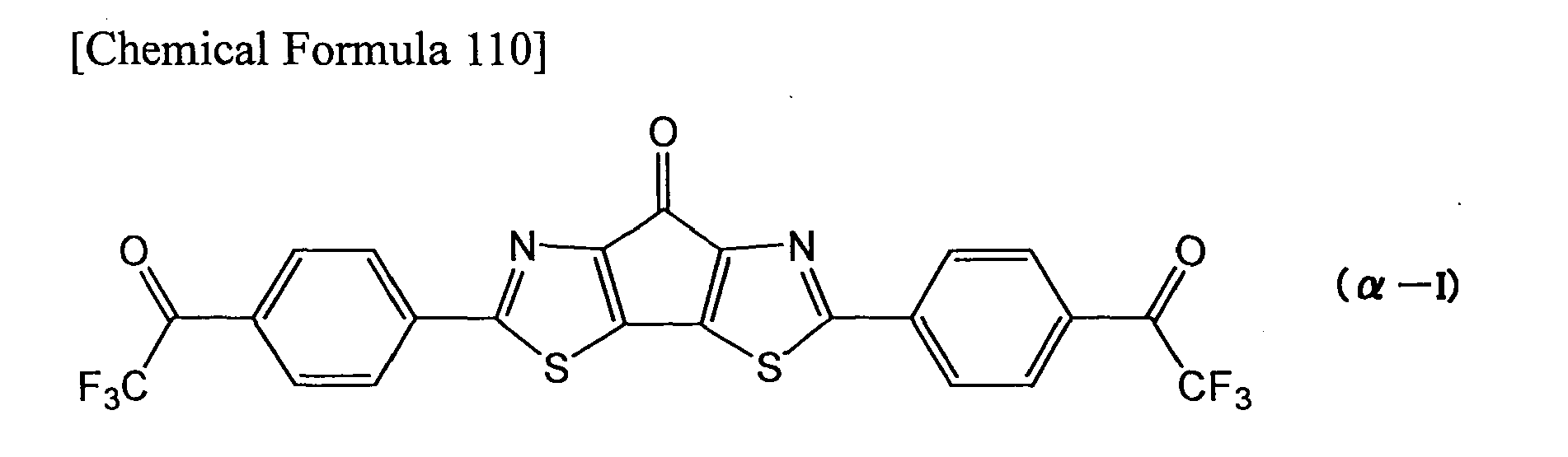
- Compound α-I was subjected to X-ray structural analysis to measure the torsional angle between adjacently bonded molecular rings, by which highly planarity of 11-12 degrees was confirmed (
Fig. 13 ). In addition, the molecular crystals exhibited a π-π stack structure with the π planes between adjacent molecules opposite each other, and a plane spacing of 0.34 nm was confirmed (Fig. 14 ). - After placing compound α-H, 2-bromo-5,5-difluoro-4H-cyclopenta[b]thiophene-4,6(5H)-dione, tetrakis(triphenylphosphine)palladium(0) and toluene in a heat-dried stoppered test tube, the mixture was exchanged with nitrogen and refluxed. The product was reacted with acetic acid and concentrated hydrochloric acid at 100°C to obtain compound α-J represented by the following formula (α-J) as the target substance.

- After placing compound α-H, compound α-L represented by the following formula (α-L), tetrakis(triphenylphosphine)palladium(0) and toluene in a heat-dried stoppered test tube, the mixture was exchanged with nitrogen and refluxed. The product was reacted with acetic acid and concentrated hydrochloric acid at 100°C to obtain compound α-K represented by the following formula (α-K) as the target substance.


- A substrate was prepared by forming a silicon oxide film as the insulating layer, by thermal oxidation to a thickness of 300 nm on the surface of a highly doped p-type silicon substrate as the gate electrode. The lift-off method was used to form on this substrate a comb-shaped source electrode and drain electrode with a channel width of 38 mm and a channel length of 5 µm. The electrode-formed substrate was subjected to ultrasonic cleaning for 10 minutes in acetone and for 10 minutes in isopropyl alcohol, after which it was irradiated with ozone UV for 30 minutes to clean the surface. An organic thin film of compound α-I was accumulated on the cleaned substrate to a film thickness of 10 mm using compound α-I synthesized in Example α-2, by vacuum vapor deposition at a substrate temperature of 110°C and a deposition rate of 0.2 nm/min, to fabricate an organic thin-
film device 1. The organic transistor property was measured by varying the gate voltage Vg from 0 to 120 V and the source-drain voltage Vsd from 0 to 100 V for the organic thin-film device 1 in a vacuum, and a satisfactory n-type semiconductor Id-Vg characteristic was obtained. The mobility during this time was 5.6 × 10⁻² cm2/Vs, the threshold voltage was 20 V and the on/off ratio was satisfactory at 106. This confirmed that the organic thin-film device 1 using compound α-I effectively functions as an n-type organic transistor, and that compound α-I can be utilized as an organic n-type semiconductor with an excellent electron transport property. - The
organic transistor device 1 also exhibited a satisfactory transistor property when operated in air (approximately 20°C), during which the mobility was 1.6 × 10⁻³ cm2/Vs. - A substrate was prepared by forming a silicon oxide film as the insulating layer, by thermal oxidation to a thickness of 300 nm on the surface of a highly doped p-type silicon substrate as the gate electrode. The substrate was subjected to ultrasonic cleaning for 10 minutes in acetone and for 10 minutes in isopropyl alcohol, after which it was irradiated with ozone UV for 30 minutes to clean the surface. An organic thin film of compound α-I was accumulated on the cleaned substrate to a film thickness of 10 nm by vacuum vapor deposition under conditions with a substrate temperature of 110°C and a deposition rate of 0.2 angstrom/sec. Au was formed to a thickness of 20 nm on the organic thin film by vapor deposition through a shadow mask, to form a source electrode and drain electrode with a channel width of 5.0 mm and a channel length of 50 µm, thus fabricating an organic thin-
film device 2. The transistor property was measured by varying the gate voltage Vg and the source-drain voltage Vsd for the obtained organic thin-film device 2 in a vacuum, and a satisfactory Id-Vg characteristic was obtained. The mobility during this time was 1.6 × 10⁻² cm2/Vs, the threshold voltage was 41 V and the on/off ratio was satisfactory at 104. This confirmed that the organic thin-film device 2 using compound α-I effectively functions as an n-type organic transistor and, as in Example α-5, that compound α-I can be utilized as an organic n-type semiconductor with an excellent electron transport property. - Also, when the
organic transistor device 2 was annealed for 30 minutes at 130°C in a vacuum, the transistor property was improved and the mobility was 2.6 × 10⁻² cm2/Vs. - When the
organic transistor device 2 was operated in air (approximately 28°C), it also exhibited a satisfactory transistor property during which the mobility was 2.1 × 10⁻² cm2/Vs. Even after standing in air (approximately 28°C) for 24 hours, theorganic transistor device 2 had a mobility of 1.3 × 10⁻² cm2/Vs, thus confirming its stability in air. - After placing 5,5'-dibromo-bithiophene (242 mg, 0.75 mmol), 4-acetylphenylboronic acid (366 mg, 2.23 mmol), tetrakis(triphenylphosphine)palladium(0) (40 mg, 0.05 mmol), NaHCO3 (438 mg, 521 mmol) and a DME/water mixed solvent (7 mL) in a heat-dried stoppered test tube, it was exchanged with nitrogen and reaction was conducted at 100°C. After 14 hours, the mixture was concentrated under reduced pressure to obtain a solid. The obtained solid was rinsed with methanol and ether and then subjected to sublimation purification in a vacuum, to obtain compound α-M represented by the following formula (α-M) as the target product (205 mg, 83% yield), as a light yellow solid. The reduction potential of compound α-M was unmeasurable because the compound was insoluble.
TLC Rf = 0.0(chloroform): 1H-NNM (400 MHz, CDCl3):δ 7.96 (m, 2H), 7.68 (m, 2H), 7.36 (m, 2H), 7.23 (m, 2H), 2.60 (s, 3H):GC-MS (DI):m/z = 402 (M+).
- Organic thin-
film device 3 was fabricated in the same manner as Example α-5, except that the organic thin film was formed of compound α-M synthesized in Comparative Example α-1 instead of compound α-I synthesized in Example α-2. The organic transistor property was measured by varying the gate voltage Vg from 0 to 100 V and the source-drain voltage Vsd from 0 to 100 V for the organic thin-film device 3 in a vacuum, to obtain the n-type semiconductor Id-Vg characteristic. The mobility during this time was 1.8 × 10⁻⁵ cm2/Vs, and the on/off ratio was low at 102. - As explained above, according to the first invention group it is possible to provide novel conjugated compounds that can be used as organic n-type semiconductors with excellent electron transport properties. It is also possible to provide organic thin films containing the novel conjugated compounds, and organic thin-film devices comprising the organic thin films.
- According to the second invention group, it is possible to provide novel nitrogen-containing fused-ring compounds and novel nitrogen-containing fused-ring polymers that can be used as organic n-type semiconductors with excellent electron transport properties. It is also possible to provide organic thin films containing the nitrogen-containing fused-ring compounds or nitrogen-containing fused-ring polymers, and organic thin-film devices comprising the organic thin films.
Claims (28)
- A conjugated compound having two or more groups represented by the following formula (I) or formula (II):

- The conjugated compound according to claim 1, wherein the group represented by formula (I) is a group represented by the following formula (III):


- The conjugated compound according to claim 2 having two or more groups represented by formula (III).
- The conjugated compound according to claim 3, wherein the conjugated compound having two or more groups represented by formula (III) is a conjugated compound represented by the following formula (V):

- The conjugated compound according to claim 4, wherein at least one group of Ar1, Ar2 and Ar3 is an optionally substituted thienylene group, with the proviso that the group as a whole contains no fluorine atoms.
- The conjugated compound according to claim 1, wherein the group represented by formula (II) is a group represented by the following formula (IV):


- The conjugated compound according to claim 6 having two or more groups represented by formula (IV).
- The conjugated compound according to claim 7, wherein the conjugated compound having two or more groups represented by formula (IV) is a conjugated compound represented by the following formula (VI):

- The conjugated compound according to any one of claims 6 to 8, wherein each Z2 is a group represented by formula (xii).
- An organic thin film comprising the conjugated compound according to any one of claims 1 to 9.
- An organic thin-film device comprising the organic thin film according to claim 10.
- An organic thin-film transistor comprising:a source electrode and drain electrode;an organic semiconductor layer that is to serve as a current channel between the electrodes; anda gate electrode that is to control the level of current flowing through the current channel; wherein the organic semiconductor layer comprises the organic thin film according to claim 10.
- An organic solar cell comprising the organic thin film according to claim 10.
- An optical sensor comprising the organic thin film according to claim 10.
- A nitrogen-containing fused-ring compound represented by the following formula (α-I):


- The nitrogen-containing fused-ring compound according to claim 15, wherein Z21 and Z22 are groups represented by formula (α-ii).
- The nitrogen-containing fused-ring compound according to claim 15 represented by the following formula (α-1-1):


- The nitrogen-containing fused-ring compound according to claim 15, wherein at least one of R21 and R22 is a group represented by the following formula (IV):


- A nitrogen-containing fused-ring polymer having a repeating unit represented by the following formula (α-II):


- The nitrogen-containing fused-ring polymer according to claim 19, wherein Z21 and Z22 are groups represented by formula (α-ii).
- The nitrogen-containing fused-ring polymer according to claim 19 or 20, having at least one repeating unit represented by the formula (α-II) and at least one repeating unit represented by the following formula (α-III):

- The nitrogen-containing fused-ring polymer according to claim 21, wherein Ar21 is a group represented by the following formula (α-IV):


- The nitrogen-containing fused-ring polymer according to claim 22, wherein Z23 is a group represented by formula (α-ii).
- An organic thin film comprising the nitrogen-containing fused-ring compound according to any one of claims 15 to 18 and/or the nitrogen-containing fused-ring polymer according to any one of claims 19 to 23.
- An organic thin-film device comprising the organic thin film according to claim 24.
- An organic thin-film transistor comprising the organic thin film according to claim 24.
- An organic solar cell comprising the organic thin film according to claim 24.
- An optical sensor comprising the organic thin film according to claim 24.
Priority Applications (1)
| Application Number | Priority Date | Filing Date | Title |
|---|---|---|---|
| EP12176179A EP2520572A1 (en) | 2007-11-30 | 2008-11-27 | Nitrogen-containing fused-ring compound, polymer comprising a nitrogen-containing fused-ring repeating unit, organic thin film, and organic thin film element |
Applications Claiming Priority (4)
| Application Number | Priority Date | Filing Date | Title |
|---|---|---|---|
| JP2007311381 | 2007-11-30 | ||
| JP2008031972 | 2008-02-13 | ||
| JP2008220031A JP5363771B2 (en) | 2008-02-13 | 2008-08-28 | Nitrogen-containing condensed ring compound, nitrogen-containing condensed ring polymer, organic thin film and organic thin film element |
| PCT/JP2008/071520 WO2009069687A1 (en) | 2007-11-30 | 2008-11-27 | Conjugated compound, nitrogenated condensed-ring compound, nitrogenated condensed-ring polymer, organic thin film, and organic thin film element |
Publications (2)
| Publication Number | Publication Date |
|---|---|
| EP2223918A1 true EP2223918A1 (en) | 2010-09-01 |
| EP2223918A4 EP2223918A4 (en) | 2012-03-14 |
Family
ID=42357931
Family Applications (2)
| Application Number | Title | Priority Date | Filing Date |
|---|---|---|---|
| EP08853653A Withdrawn EP2223918A4 (en) | 2007-11-30 | 2008-11-27 | Conjugated compound, nitrogenated condensed-ring compound, nitrogenated condensed-ring polymer, organic thin film, and organic thin film element |
| EP12176179A Withdrawn EP2520572A1 (en) | 2007-11-30 | 2008-11-27 | Nitrogen-containing fused-ring compound, polymer comprising a nitrogen-containing fused-ring repeating unit, organic thin film, and organic thin film element |
Family Applications After (1)
| Application Number | Title | Priority Date | Filing Date |
|---|---|---|---|
| EP12176179A Withdrawn EP2520572A1 (en) | 2007-11-30 | 2008-11-27 | Nitrogen-containing fused-ring compound, polymer comprising a nitrogen-containing fused-ring repeating unit, organic thin film, and organic thin film element |
Country Status (6)
| Country | Link |
|---|---|
| US (1) | US8378338B2 (en) |
| EP (2) | EP2223918A4 (en) |
| KR (1) | KR20100099225A (en) |
| CN (1) | CN101878207A (en) |
| TW (1) | TWI421246B (en) |
| WO (1) | WO2009069687A1 (en) |
Cited By (6)
| Publication number | Priority date | Publication date | Assignee | Title |
|---|---|---|---|---|
| WO2012118128A1 (en) * | 2011-03-03 | 2012-09-07 | 住友化学株式会社 | Polymer and organic thin film and organic thin film element using same |
| WO2013023106A1 (en) * | 2011-08-10 | 2013-02-14 | Georgia Tech Research Corporation | Coupled heteroaryl compounds via rearrangement of halogenated heteroaromatics followed by oxidative coupling (acyl moieties) |
| WO2013023107A1 (en) * | 2011-08-10 | 2013-02-14 | Georgia Tech Research Corporation | Coupled heteroaryl compounds via rearrangement of halogenated heteroaromatics followed by oxidative coupling (electron withdrawing groups) |
| WO2013023108A1 (en) * | 2011-08-10 | 2013-02-14 | Georgia Tech Research Corporation | Coupled heteroaryl compounds via rearrangement of halogenated heteroaromatics followed by oxidative coupling (heteroarylene spacer moiety) |
| WO2013023109A1 (en) * | 2011-08-10 | 2013-02-14 | Georgia Tech Research Corporation | Coupled heteroaryl compounds via rearrangement of halogenated heteroaromatics followed by oxidative coupling (coupled tricyclic core compounds) |
| EP3523835B1 (en) | 2016-10-05 | 2022-11-16 | Raynergy Tek Inc. | Organic photodetector |
Families Citing this family (12)
| Publication number | Priority date | Publication date | Assignee | Title |
|---|---|---|---|---|
| JP2010209264A (en) * | 2009-03-11 | 2010-09-24 | Sumitomo Chemical Co Ltd | Fluorine-containing polymer and organic thin film using the same |
| JP5426199B2 (en) * | 2009-03-11 | 2014-02-26 | 住友化学株式会社 | Branched compound, organic thin film and organic thin film element using the same |
| EP2534146A1 (en) * | 2010-02-10 | 2012-12-19 | Georgia Tech Research Corporation | Method of making coupled heteroaryl compounds via rearrangement of halogenated heteroaromatics followed by oxidative coupling |
| JP5792482B2 (en) | 2010-03-04 | 2015-10-14 | 住友化学株式会社 | Nitrogen-containing condensed ring compound, nitrogen-containing condensed ring polymer, organic thin film and organic thin film element |
| JP2012051874A (en) * | 2010-07-28 | 2012-03-15 | Sumitomo Chemical Co Ltd | Condensed ring compound, organic thin film, and organic thin film element |
| CN102344553B (en) * | 2010-08-03 | 2014-02-19 | 海洋王照明科技股份有限公司 | Naphthalenetetracarboxylic acid diimide organic semiconductor material, preparation process thereof and application thereof |
| EP2601236B1 (en) | 2010-08-05 | 2016-11-02 | Basf Se | Semiconductor materials prepared from bridged bithiazole copolymers |
| JP2012126876A (en) * | 2010-11-24 | 2012-07-05 | Sumitomo Chemical Co Ltd | Conjugated compound, and organic thin film and organic thin film device using the same |
| KR20140007396A (en) * | 2011-01-31 | 2014-01-17 | 스미또모 가가꾸 가부시키가이샤 | Nitrogen-containing condensed ring compound, nitrogen-containing condensed ring polymer, organic thin film, and organic thin film element |
| JP5780402B2 (en) * | 2011-12-27 | 2015-09-16 | ソニー株式会社 | Semiconductor element, semiconductor element manufacturing method, solid-state imaging device, and electronic apparatus |
| US9234112B2 (en) * | 2013-06-05 | 2016-01-12 | Korea Institute Of Machinery & Materials | Metal precursor powder, method of manufacturing conductive metal layer or pattern, and device including the same |
| KR102282495B1 (en) | 2014-07-21 | 2021-07-27 | 삼성전자주식회사 | Compound, organic optoelectronic device and image sensor |
Citations (2)
| Publication number | Priority date | Publication date | Assignee | Title |
|---|---|---|---|---|
| DE112006002392T5 (en) * | 2005-09-08 | 2008-10-02 | Sumitomo Chemical Co. Ltd. | A polymer comprising a unit comprising a fluorocyclopentane ring condensed with an aromatic ring, and organic thin film and organic thin film element comprising both thereof |
| EP2123690A1 (en) * | 2007-03-07 | 2009-11-25 | Sumitomo Chemical Company, Limited | Polymer having unit obtained by condensation of difluorocyclopentanedione ring and aromatic ring, organic thin film using the same, and organic thin film device |
Family Cites Families (35)
| Publication number | Priority date | Publication date | Assignee | Title |
|---|---|---|---|---|
| US5093432A (en) * | 1988-09-28 | 1992-03-03 | Exfluor Research Corporation | Liquid phase fluorination |
| GB8826237D0 (en) | 1988-11-09 | 1988-12-14 | Univ Belfast | Fingerprint reagent |
| JPH05110069A (en) | 1991-10-14 | 1993-04-30 | Mitsubishi Electric Corp | Manufacture of field effect transistor |
| JPH06135869A (en) | 1992-10-28 | 1994-05-17 | Sagami Chem Res Center | Production of compound having perfluoroalkyl group |
| US6249369B1 (en) * | 1999-07-09 | 2001-06-19 | Gentex Corporation | Coupled electrochromic compounds with photostable dication oxidation states |
| JP3716732B2 (en) | 1999-12-27 | 2005-11-16 | 株式会社豊田中央研究所 | Organic compound and element using the same |
| US6585914B2 (en) | 2000-07-24 | 2003-07-01 | Northwestern University | N-type thiophene semiconductors |
| EP1279689B1 (en) | 2001-07-25 | 2008-10-01 | MERCK PATENT GmbH | Mono-, Oligo and Poly-3-(1,1-difluoroalkyl)thiophenes and their use as charge transport materials |
| JP4234952B2 (en) | 2002-05-31 | 2009-03-04 | 株式会社リコー | Vertical organic transistor |
| US6984461B2 (en) * | 2002-06-21 | 2006-01-10 | Samsung Sdi Co., Ltd. | Blue electroluminescent polymer and organic-electroluminescent device using the same |
| JP4374174B2 (en) | 2002-09-18 | 2009-12-02 | 日本放送協会 | Organic thin film device and organic EL display |
| US6960643B2 (en) | 2003-03-19 | 2005-11-01 | Xerox Corporation | Fluorinated polythiophenes and devices thereof |
| US6855951B2 (en) | 2003-03-19 | 2005-02-15 | Xerox Corporation | Fluorinated polythiophenes and devices thereof |
| EP1477504A1 (en) | 2003-05-16 | 2004-11-17 | MERCK PATENT GmbH | Mono-, oligo- and polymers comprising dithienotiophene and aryl groups |
| US7244809B2 (en) | 2003-05-16 | 2007-07-17 | Merck Patent Gmbh | Mono-, oligo- and polymers comprising dithienothiophene and aryl groups |
| KR100682860B1 (en) * | 2004-01-27 | 2007-02-15 | 삼성에스디아이 주식회사 | Spirofluorene-based polymer and organo-electroluminescent device using the same |
| JP2005235923A (en) | 2004-02-18 | 2005-09-02 | Nippon Hoso Kyokai <Nhk> | Organic thin film transistor, method of manufacturing the same, and organic thin film device |
| US7375176B2 (en) * | 2004-03-31 | 2008-05-20 | Litt Morton H | Liquid crystal poly(phenylene sulfonic acids) |
| US7312469B2 (en) * | 2004-06-10 | 2007-12-25 | Xerox Corporation | Device with small molecular thiophene compound |
| JPWO2005122278A1 (en) * | 2004-06-10 | 2008-04-10 | コニカミノルタホールディングス株式会社 | Organic semiconductor thin film, organic semiconductor device, organic thin film transistor, and organic electroluminescence element |
| CN1976883A (en) * | 2004-06-28 | 2007-06-06 | 出光兴产株式会社 | Polycyclic aromatic compound, material for forming light-emitting coating film using the same, and organic electroluminescent device |
| EP1627891A1 (en) | 2004-08-11 | 2006-02-22 | Covion Organic Semiconductors GmbH | Polymers for use in organic electroluminescent devices |
| EP1831205A4 (en) * | 2004-09-14 | 2010-12-01 | Univ Northwestern | Carbonyl-functionalized thiophene compounds and related device structures |
| US20060094859A1 (en) * | 2004-11-03 | 2006-05-04 | Marrocco Matthew L Iii | Class of bridged biphenylene polymers |
| JP2006140235A (en) * | 2004-11-10 | 2006-06-01 | Idemitsu Kosan Co Ltd | Organic electroluminescence element |
| KR101202340B1 (en) * | 2005-01-21 | 2012-11-16 | 삼성디스플레이 주식회사 | Blue electroluminescent compound and organo-electroluminescent device employing the same |
| US20060237695A1 (en) * | 2005-03-16 | 2006-10-26 | Plextronics, Inc. | Copolymers of soluble poly(thiophenes) with improved electronic performance |
| JPWO2006098121A1 (en) * | 2005-03-16 | 2008-08-21 | コニカミノルタホールディングス株式会社 | Organic semiconductor material, organic semiconductor film, organic semiconductor device, organic thin film transistor, and method for forming organic thin film transistor |
| JP2007116115A (en) | 2005-09-21 | 2007-05-10 | Mitsubishi Chemicals Corp | Organic semiconductor material and organic field-effect transistor |
| DE102005060438A1 (en) | 2005-12-17 | 2007-06-21 | Merck Patent Gmbh | Substitution of indenofluorenes |
| JP5063004B2 (en) * | 2006-01-26 | 2012-10-31 | 住友精化株式会社 | (Thiophene / phenylene) co-oligomer and light-emitting material containing them |
| KR101288304B1 (en) * | 2006-01-27 | 2013-07-18 | 삼성디스플레이 주식회사 | Organic light emitting compound and organic light emitting device comprising the same |
| US20090256475A1 (en) * | 2006-09-13 | 2009-10-15 | Tomoya Nakatani | Polymer compound and polymer light emitting device |
| JP2008255097A (en) | 2007-03-09 | 2008-10-23 | Sumitomo Chemical Co Ltd | Fluorine-containing polycyclic aromatic compound, fluorine-containing polymer, organic thin film and organic thin film element |
| KR101490246B1 (en) * | 2007-07-02 | 2015-02-05 | 엘지전자 주식회사 | broadcasting receiver and method of processing broadcast signal |
-
2008
- 2008-11-27 KR KR1020107014409A patent/KR20100099225A/en not_active Application Discontinuation
- 2008-11-27 EP EP08853653A patent/EP2223918A4/en not_active Withdrawn
- 2008-11-27 CN CN200880118465XA patent/CN101878207A/en active Pending
- 2008-11-27 US US12/745,481 patent/US8378338B2/en not_active Expired - Fee Related
- 2008-11-27 EP EP12176179A patent/EP2520572A1/en not_active Withdrawn
- 2008-11-27 WO PCT/JP2008/071520 patent/WO2009069687A1/en active Application Filing
- 2008-11-28 TW TW097146130A patent/TWI421246B/en not_active IP Right Cessation
Patent Citations (2)
| Publication number | Priority date | Publication date | Assignee | Title |
|---|---|---|---|---|
| DE112006002392T5 (en) * | 2005-09-08 | 2008-10-02 | Sumitomo Chemical Co. Ltd. | A polymer comprising a unit comprising a fluorocyclopentane ring condensed with an aromatic ring, and organic thin film and organic thin film element comprising both thereof |
| EP2123690A1 (en) * | 2007-03-07 | 2009-11-25 | Sumitomo Chemical Company, Limited | Polymer having unit obtained by condensation of difluorocyclopentanedione ring and aromatic ring, organic thin film using the same, and organic thin film device |
Non-Patent Citations (5)
| Title |
|---|
| KELLER P A ET AL: "Oxidative coupling of indoles using thallium(III) trifluoroacetate", TETRAHEDRON, ELSEVIER SCIENCE PUBLISHERS, AMSTERDAM, NL, vol. 64, no. 33, 11 August 2008 (2008-08-11), pages 7787-7795, XP022807788, ISSN: 0040-4020, DOI: 10.1016/J.TET.2008.05.133 [retrieved on 2008-06-05] * |
| NENAJDENKO V G ET AL: "Synthesis of aminoalkylpyrazoles and-isoxazoles from cyclic [beta]-(trifluoroacetyl) enamines", RUSSIAN CHEMICAL BULLETIN, KLUWER ACADEMIC PUBLISHERS-PLENUM PUBLISHERS, NE, vol. 56, no. 2, 1 February 2007 (2007-02-01), pages 336-344, XP019533496, ISSN: 1573-9171, DOI: 10.1007/S11172-007-0055-7 * |
| See also references of WO2009069687A1 * |
| YUTAKA IE ET AL: "Electronegative Oligothiophenes Based on Difluorodioxocyclopentene-Annelated Thiophenes: Synthesis, Properties, and n-Type FET Performances", ORGANIC LETTERS, vol. 10, no. 5, 1 March 2008 (2008-03-01), pages 833-836, XP55004870, ISSN: 1523-7060, DOI: 10.1021/ol7029678 * |
| YUTAKA IE ET AL: "Perfluoroalkyl-annelated conjugated systems toward n-type organic semiconductors", PURE AND APPLIED CHEMISTRY, vol. 80, no. 3, 1 January 2008 (2008-01-01), pages 589-597, XP55004922, ISSN: 0033-4545, DOI: 10.1351/pac200880030589 * |
Cited By (6)
| Publication number | Priority date | Publication date | Assignee | Title |
|---|---|---|---|---|
| WO2012118128A1 (en) * | 2011-03-03 | 2012-09-07 | 住友化学株式会社 | Polymer and organic thin film and organic thin film element using same |
| WO2013023106A1 (en) * | 2011-08-10 | 2013-02-14 | Georgia Tech Research Corporation | Coupled heteroaryl compounds via rearrangement of halogenated heteroaromatics followed by oxidative coupling (acyl moieties) |
| WO2013023107A1 (en) * | 2011-08-10 | 2013-02-14 | Georgia Tech Research Corporation | Coupled heteroaryl compounds via rearrangement of halogenated heteroaromatics followed by oxidative coupling (electron withdrawing groups) |
| WO2013023108A1 (en) * | 2011-08-10 | 2013-02-14 | Georgia Tech Research Corporation | Coupled heteroaryl compounds via rearrangement of halogenated heteroaromatics followed by oxidative coupling (heteroarylene spacer moiety) |
| WO2013023109A1 (en) * | 2011-08-10 | 2013-02-14 | Georgia Tech Research Corporation | Coupled heteroaryl compounds via rearrangement of halogenated heteroaromatics followed by oxidative coupling (coupled tricyclic core compounds) |
| EP3523835B1 (en) | 2016-10-05 | 2022-11-16 | Raynergy Tek Inc. | Organic photodetector |
Also Published As
| Publication number | Publication date |
|---|---|
| WO2009069687A1 (en) | 2009-06-04 |
| KR20100099225A (en) | 2010-09-10 |
| CN101878207A (en) | 2010-11-03 |
| TW200934767A (en) | 2009-08-16 |
| EP2223918A4 (en) | 2012-03-14 |
| US20100301314A1 (en) | 2010-12-02 |
| US8378338B2 (en) | 2013-02-19 |
| TWI421246B (en) | 2014-01-01 |
| EP2520572A1 (en) | 2012-11-07 |
Similar Documents
| Publication | Publication Date | Title |
|---|---|---|
| US8378338B2 (en) | Conjugated compound, nitrogenated condensed-ring compound, nitrogenated condensed-ring polymer, organic thin film, and organic thin film element | |
| US8158275B2 (en) | Fluorine-containing compound and method for producing same, fluorine-containing polymer, organic thin film, and organic thin film device | |
| EP2133321A1 (en) | Fluorine-containing polycyclic aromatic compound, fluorine-containing polymer, organic thin film and organic thin film device | |
| EP2123690A1 (en) | Polymer having unit obtained by condensation of difluorocyclopentanedione ring and aromatic ring, organic thin film using the same, and organic thin film device | |
| JP4931118B2 (en) | POLYMER CONTAINING CONDENSATION OF FLUORINATED CYCLOPENTANE RING AND AROMATIC RING, ORGANIC THIN FILM AND ORGANIC THIN FILM DEVICE USING SAME | |
| EP2251335A1 (en) | Branched compounds, organic thin films made by using the same, and organic thin film devices | |
| JP2009215546A (en) | Polycyclic fused ring compound, polycyclic fused ring polymer and organic thin film containing them | |
| WO2012070582A1 (en) | Conjugated compound, and organic thin film and organic thin film element using same | |
| EP2407465A1 (en) | Conjugated compound, and organic thin film and organic thin film element each comprising same | |
| WO2010104042A1 (en) | Fluoropolymer and thin organic film comprising same | |
| EP2407464A1 (en) | Branched compound, and organic thin film and organic thin film element each comprising same | |
| JP2012184227A (en) | Compound having acceptor group, and organic thin film and organic thin film element produced by using the same | |
| WO2010104037A1 (en) | Polymer, organic thin film comprising the polymer, and organic thin-film element including same | |
| JP5363771B2 (en) | Nitrogen-containing condensed ring compound, nitrogen-containing condensed ring polymer, organic thin film and organic thin film element | |
| JP5105581B2 (en) | Fluorine-containing compound and method for producing the same, fluorine-containing polymer, organic thin film, and organic thin film element | |
| JP5342852B2 (en) | Conjugated compound, organic thin film and organic thin film element using the same | |
| WO2011102390A1 (en) | Aromatic compound, organic thin film using same, and organic thin film element provided with said organic thin film | |
| JP2009215543A (en) | Polymer, organic thin film using the same and organic thin film device |
Legal Events
| Date | Code | Title | Description |
|---|---|---|---|
| PUAI | Public reference made under article 153(3) epc to a published international application that has entered the european phase |
Free format text: ORIGINAL CODE: 0009012 |
|
| 17P | Request for examination filed |
Effective date: 20100617 |
|
| AK | Designated contracting states |
Kind code of ref document: A1 Designated state(s): AT BE BG CH CY CZ DE DK EE ES FI FR GB GR HR HU IE IS IT LI LT LU LV MC MT NL NO PL PT RO SE SI SK TR |
|
| AX | Request for extension of the european patent |
Extension state: AL BA MK RS |
|
| DAX | Request for extension of the european patent (deleted) | ||
| A4 | Supplementary search report drawn up and despatched |
Effective date: 20120213 |
|
| RIC1 | Information provided on ipc code assigned before grant |
Ipc: H01M 14/00 20060101ALI20120207BHEP Ipc: H01L 51/42 20060101ALI20120207BHEP Ipc: H01L 51/30 20060101ALI20120207BHEP Ipc: H01L 51/05 20060101ALI20120207BHEP Ipc: H01L 29/80 20060101ALI20120207BHEP Ipc: H01L 29/786 20060101ALI20120207BHEP Ipc: C07D 417/14 20060101ALI20120207BHEP Ipc: C07D 409/14 20060101ALI20120207BHEP Ipc: C07D 333/78 20060101ALI20120207BHEP Ipc: C07D 277/60 20060101ALI20120207BHEP Ipc: C07D 333/22 20060101AFI20120207BHEP |
|
| RAP1 | Party data changed (applicant data changed or rights of an application transferred) |
Owner name: SUMITOMO CHEMICAL COMPANY, LIMITED |
|
| 17Q | First examination report despatched |
Effective date: 20120910 |
|
| STAA | Information on the status of an ep patent application or granted ep patent |
Free format text: STATUS: THE APPLICATION IS DEEMED TO BE WITHDRAWN |
|
| 18D | Application deemed to be withdrawn |
Effective date: 20130122 |