WO2011102390A1 - Aromatic compound, organic thin film using same, and organic thin film element provided with said organic thin film - Google Patents
Aromatic compound, organic thin film using same, and organic thin film element provided with said organic thin film Download PDFInfo
- Publication number
- WO2011102390A1 WO2011102390A1 PCT/JP2011/053287 JP2011053287W WO2011102390A1 WO 2011102390 A1 WO2011102390 A1 WO 2011102390A1 JP 2011053287 W JP2011053287 W JP 2011053287W WO 2011102390 A1 WO2011102390 A1 WO 2011102390A1
- Authority
- WO
- WIPO (PCT)
- Prior art keywords
- group
- thin film
- organic thin
- aromatic compound
- formula
- Prior art date
Links
Images


Classifications
-
- C—CHEMISTRY; METALLURGY
- C07—ORGANIC CHEMISTRY
- C07D—HETEROCYCLIC COMPOUNDS
- C07D495/00—Heterocyclic compounds containing in the condensed system at least one hetero ring having sulfur atoms as the only ring hetero atoms
- C07D495/02—Heterocyclic compounds containing in the condensed system at least one hetero ring having sulfur atoms as the only ring hetero atoms in which the condensed system contains two hetero rings
- C07D495/04—Ortho-condensed systems
-
- C—CHEMISTRY; METALLURGY
- C07—ORGANIC CHEMISTRY
- C07D—HETEROCYCLIC COMPOUNDS
- C07D519/00—Heterocyclic compounds containing more than one system of two or more relevant hetero rings condensed among themselves or condensed with a common carbocyclic ring system not provided for in groups C07D453/00 or C07D455/00
-
- H—ELECTRICITY
- H10—SEMICONDUCTOR DEVICES; ELECTRIC SOLID-STATE DEVICES NOT OTHERWISE PROVIDED FOR
- H10K—ORGANIC ELECTRIC SOLID-STATE DEVICES
- H10K85/00—Organic materials used in the body or electrodes of devices covered by this subclass
- H10K85/60—Organic compounds having low molecular weight
- H10K85/649—Aromatic compounds comprising a hetero atom
- H10K85/655—Aromatic compounds comprising a hetero atom comprising only sulfur as heteroatom
-
- H—ELECTRICITY
- H10—SEMICONDUCTOR DEVICES; ELECTRIC SOLID-STATE DEVICES NOT OTHERWISE PROVIDED FOR
- H10K—ORGANIC ELECTRIC SOLID-STATE DEVICES
- H10K85/00—Organic materials used in the body or electrodes of devices covered by this subclass
- H10K85/60—Organic compounds having low molecular weight
- H10K85/649—Aromatic compounds comprising a hetero atom
- H10K85/657—Polycyclic condensed heteroaromatic hydrocarbons
- H10K85/6576—Polycyclic condensed heteroaromatic hydrocarbons comprising only sulfur in the heteroaromatic polycondensed ring system, e.g. benzothiophene
-
- H—ELECTRICITY
- H10—SEMICONDUCTOR DEVICES; ELECTRIC SOLID-STATE DEVICES NOT OTHERWISE PROVIDED FOR
- H10K—ORGANIC ELECTRIC SOLID-STATE DEVICES
- H10K10/00—Organic devices specially adapted for rectifying, amplifying, oscillating or switching; Organic capacitors or resistors having a potential-jump barrier or a surface barrier
- H10K10/40—Organic transistors
- H10K10/46—Field-effect transistors, e.g. organic thin-film transistors [OTFT]
- H10K10/462—Insulated gate field-effect transistors [IGFETs]
- H10K10/464—Lateral top-gate IGFETs comprising only a single gate
-
- H—ELECTRICITY
- H10—SEMICONDUCTOR DEVICES; ELECTRIC SOLID-STATE DEVICES NOT OTHERWISE PROVIDED FOR
- H10K—ORGANIC ELECTRIC SOLID-STATE DEVICES
- H10K10/00—Organic devices specially adapted for rectifying, amplifying, oscillating or switching; Organic capacitors or resistors having a potential-jump barrier or a surface barrier
- H10K10/40—Organic transistors
- H10K10/46—Field-effect transistors, e.g. organic thin-film transistors [OTFT]
- H10K10/462—Insulated gate field-effect transistors [IGFETs]
- H10K10/466—Lateral bottom-gate IGFETs comprising only a single gate
-
- Y—GENERAL TAGGING OF NEW TECHNOLOGICAL DEVELOPMENTS; GENERAL TAGGING OF CROSS-SECTIONAL TECHNOLOGIES SPANNING OVER SEVERAL SECTIONS OF THE IPC; TECHNICAL SUBJECTS COVERED BY FORMER USPC CROSS-REFERENCE ART COLLECTIONS [XRACs] AND DIGESTS
- Y02—TECHNOLOGIES OR APPLICATIONS FOR MITIGATION OR ADAPTATION AGAINST CLIMATE CHANGE
- Y02E—REDUCTION OF GREENHOUSE GAS [GHG] EMISSIONS, RELATED TO ENERGY GENERATION, TRANSMISSION OR DISTRIBUTION
- Y02E10/00—Energy generation through renewable energy sources
- Y02E10/50—Photovoltaic [PV] energy
- Y02E10/549—Organic PV cells
-
- Y—GENERAL TAGGING OF NEW TECHNOLOGICAL DEVELOPMENTS; GENERAL TAGGING OF CROSS-SECTIONAL TECHNOLOGIES SPANNING OVER SEVERAL SECTIONS OF THE IPC; TECHNICAL SUBJECTS COVERED BY FORMER USPC CROSS-REFERENCE ART COLLECTIONS [XRACs] AND DIGESTS
- Y02—TECHNOLOGIES OR APPLICATIONS FOR MITIGATION OR ADAPTATION AGAINST CLIMATE CHANGE
- Y02P—CLIMATE CHANGE MITIGATION TECHNOLOGIES IN THE PRODUCTION OR PROCESSING OF GOODS
- Y02P70/00—Climate change mitigation technologies in the production process for final industrial or consumer products
- Y02P70/50—Manufacturing or production processes characterised by the final manufactured product
Definitions
- the present invention relates to an aromatic compound, an organic thin film using the same, an organic thin film element including the organic thin film, an organic thin film transistor, and an organic photoelectric conversion element.
- An organic thin film containing an organic semiconductor material having a charge (meaning electron or hole, hereinafter the same) transportability is expected to be applied to organic thin film elements such as organic thin film transistors, organic solar cells, and optical sensors.
- organic thin film elements such as organic thin film transistors, organic solar cells, and optical sensors.
- organic p-type semiconductor materials shown hole transport properties
- organic n-type semiconductor materials shown electron transport properties
- a compound having a thiophene ring such as oligothiophene or polythiophene can take a stable radical cation state, and thus is expected to exhibit high hole transportability.
- oligothiophenes having a long chain length are expected to have higher hole transportability because the conjugation length becomes longer.
- EDOT ethylenedioxythiophene
- the present invention has been made in view of such circumstances, and an object of the present invention is to provide an aromatic compound that can be applied as an organic semiconductor material having excellent charge transportability and high stability.
- Another object of the present invention is to provide an organic thin film obtained by using such an aromatic compound, and an organic thin film element provided with the organic thin film, particularly an organic thin film transistor and an organic photoelectric conversion element.
- the aromatic compound of the present invention is represented by the formula (1).
- Ar 11 represents a group forming a conjugated structure with X 11 and X 12 include an aromatic ring
- X 11 and X 12 independently formula (1a) or (1b)
- the group represented by these is shown.
- Ar 12 and Ar 13 each independently represent an aromatic hydrocarbon group having 6 or more carbon atoms
- R 11 , R 12 , R 13 and R 14 are each independently Represents a hydrogen atom, a halogen atom or a monovalent group
- X 13 , X 14 , X 15 and X 16 each independently represent an oxygen atom, a sulfur atom or a selenium atom.
- the aromatic compound of the present invention has a long and high planar conjugated structure as a whole by having a group represented by the formula (1a) or (1b) at the terminal portion. Therefore, when applied as an organic semiconductor material, excellent charge transport properties can be exhibited.
- the group represented by the formula (1a) or (1b) has an aromatic hydrocarbon group represented by Ar 12 or Ar 13 at a portion located at the end of the conjugated structure.
- Ar 12 or Ar 13 an aromatic hydrocarbon group represented by Ar 12 or Ar 13 at a portion located at the end of the conjugated structure.
- the aromatic compound has a stable molecular structure, and the charge transfer as an organic semiconductor material is repeated or a voltage is applied.
- Ar 11 is preferably a group represented by the formula (2).
- Ar 21 , Ar 22 and Ar 23 each independently have an aromatic hydrocarbon group having 6 or more carbon atoms which may have a substituent, or have a substituent.
- Ar 11 is a group having a structure containing only an aromatic hydrocarbon group and / or a heterocyclic group, the conjugation property of the aromatic compound is further increased, and a more excellent charge transport property can be obtained. become.
- At least one of X 13 and X 14 is preferably a sulfur atom, and at least one of X 15 and X 16 is preferably a sulfur atom.
- An aromatic compound having such a structure can exhibit further excellent charge transport properties.
- Ar 12 and Ar 13 are preferably a phenyl group or a naphthyl group. By having these groups at the terminal of the conjugated structure, the aromatic compound can exhibit extremely excellent stability in addition to high charge transportability.
- Ar 11 is a group represented by the formula (2), and X 13 , X 14 , X 15 and X 16 are sulfur atoms.
- Ar 12 and Ar 13 are preferably phenyl groups.
- At least one of Ar 21 , Ar 22 and Ar 23 is preferably a thiophenediyl group which may have a substituent or a thienothiophenediyl group which may have a substituent.
- the present invention also provides an organic thin film containing the aromatic compound of the present invention, and an organic thin film element comprising such an organic thin film, particularly an organic thin film transistor and an organic photoelectric conversion element. Since the organic thin film of the present invention contains the aromatic compound of the present invention, it is possible to obtain excellent charge transportability and maintain such high charge transportability over a long period of time. Therefore, an organic thin film element such as an organic thin film transistor or an organic photoelectric conversion element provided with such an organic thin film can stably exhibit high charge transportability and has excellent practicality.
- the aromatic compound applicable as an organic-semiconductor material which has the outstanding charge transport property and has high stability.
- an organic thin film containing such an aromatic compound and capable of stably exhibiting high charge transportability, and an organic thin film element such as an organic thin film transistor or an organic photoelectric conversion element having such an organic thin film are provided. It becomes possible to provide.
- the aromatic compound of the present embodiment is a conjugated compound having a structure represented by the above formula (1).
- the conjugated compound has a structure in which a single bond and an unsaturated bond, a lone electron pair, a radical, or a non-bonding orbital are alternately connected in the main skeleton of a molecule, Refers to a compound that is delocalized.
- the aromatic compound according to a preferred embodiment has a group that includes an aromatic ring and forms a conjugated structure with X 11 and X 12 as Ar 11 .
- a group may be any group as long as it has at least one aromatic ring such as an aromatic hydrocarbon ring or an aromatic heterocyclic ring and can form a conjugated structure as a whole compound. Therefore, Ar 11 may be a group that includes a chain structure other than an aromatic ring to form a conjugated structure.
- the aromatic compound according to a preferred embodiment is one in which a group represented by the formula (1a) or the formula (1b) is bonded to the group represented by Ar 11 as X 11 or X 12 .
- the group represented by the formula (1a) or the formula (1b) is included in the group represented by Ar 11 in addition to X 11 or X 12. May be.
- the aromatic compound according to a preferred embodiment has a plurality of groups represented by the formula (1a) or the formula (1b), or groups represented by the formula (1a) and the formula (1b). In combination, this has high molecular planarity as a whole. Therefore, when used as an organic semiconductor material, the aromatic compound according to a preferred embodiment is a p-type semiconductor with good molecular packing and excellent charge transportability.
- X 11 and X 12 may each independently be any of the groups represented by Formula (1a) and Formula (1b). Since the production of the aromatic compound according to the preferred embodiment can be facilitated and the packing of the molecule can be further improved, both X 11 and X 12 are groups represented by the formula (1a), or both are A group represented by the formula (1b) is more preferable. From this point of view, X 11 and X 12 are particularly preferably groups having the same structure.
- Ar 12 and Ar 13 each independently represent an aromatic hydrocarbon group having 6 or more carbon atoms.
- This aromatic hydrocarbon group may have groups represented by R 11 and R 13 .
- the aromatic hydrocarbon group refers to a group composed of the remaining atomic group obtained by removing a hydrogen atom at a site used for bonding from an aromatic hydrocarbon ring.
- the aromatic hydrocarbon group has preferably 6 to 60 carbon atoms, more preferably 6 to 20 carbon atoms.
- the aromatic hydrocarbon ring includes a benzene ring and a condensed ring
- examples of the condensed ring include a naphthalene ring, an anthracene ring, a tetracene ring, a pentacene ring, a pyrene ring, a perylene ring, and a fluorene ring.
- the aromatic hydrocarbon group a group consisting of the remaining atomic group obtained by removing two hydrogen atoms from a benzene ring or naphthalene ring is preferable.
- the aromatic hydrocarbon group may have one or more groups represented by R 11 and R 13 , but the carbon number of the aromatic hydrocarbon group described above includes the carbon number of the substituent. Suppose that it is not possible. Specific examples of the group represented by R 11 and R 13 will be described later.
- a hydrogen atom, a halogen atom, a saturated or unsaturated hydrocarbon group, an aryl group, an alkoxy group, an alkylthio group, an arylalkyl group examples include an aryloxy group, a monovalent heterocyclic group, an amino group, a nitro group, and a cyano group.
- R 11 , R 12 , R 13 and R 14 (referred to as “R 11 to R 14 ”, hereinafter, the same expressions are also expressed in the same manner) are each independently.
- a halogen atom a fluorine atom, a chlorine atom, a bromine atom, and an iodine atom are mentioned, for example.
- Examples of the monovalent group include a group consisting of a linear or branched low molecular chain, a monovalent cyclic group having 3 to 60 carbon atoms (monocyclic, condensed ring, carbocyclic or heterocyclic ring, saturated Or may be unsaturated), saturated or unsaturated hydrocarbon group, hydroxyl group, alkoxy group, alkylthio group, alkanoyloxy group, amino group, oxyamino group, alkylamino group, dialkylamino group, alkanoylamino group, cyano group , A nitro group, a sulfo group, an alkyl group substituted with a halogen atom, an alkoxysulfonyl group, an alkylsulfonyl group, a sulfamoyl group, an alkylsulfamoyl group, a carboxyl group, a carbamoyl group, an alkylcarbamoyl group, an
- R 11 to R 14 are each a hydrogen atom, an alkyl group having 1 to 20 carbon atoms, an alkoxy group having 1 to 20 carbon atoms, or an alkyl group having 1 to 20 carbon atoms. It is more preferably an alkylthio group, and further preferably a hydrogen atom or an alkyl group having 1 to 12 carbon atoms. Further, since the solubility in an organic solvent is improved, it is preferable that at least one of R 11 and R 12 and at least one of R 13 and R 14 are an alkyl group having 6 to 12 carbon atoms. In particular, since the solubility in an organic solvent is enhanced while improving the stability of the aromatic compound, R 11 and R 13 are hydrogen atoms, and R 12 and R 14 are alkyl groups having 6 to 12 carbon atoms. It is preferable.
- alkyl group examples include linear, branched or cyclic alkyl groups having 1 to 20 carbon atoms, and linear, branched or cyclic alkyl groups having 1 to 12 carbon atoms are preferable.
- alkoxy group and the alkylthio group examples include an alkoxy group having 1 to 20 carbon atoms and an alkylthio group, and those having the above alkyl group in the structure can be exemplified.
- alkoxy group and the alkylthio group those containing a linear, branched or cyclic alkyl group having 1 to 12 carbon atoms are preferable.
- X 13 to X 16 each independently represents an oxygen atom, a sulfur atom or a selenium atom.
- at least one of X 13 and X 14 is a sulfur atom
- at least one of X 15 and X 16 is a sulfur atom
- all of X 13 to X 16 are sulfur. More preferably, it is an atom.
- the Ar 11 is a group represented by the above formula (2) because a more excellent charge transport property tends to be obtained.
- Ar 21 , Ar 22 and Ar 23 are each independently an aromatic hydrocarbon group having 6 or more carbon atoms which may have a substituent, or a substituent. It is a heterocyclic group having 4 or more carbon atoms which may be present.
- aromatic hydrocarbon group include the same groups as the aromatic hydrocarbon groups exemplified as Ar 12 and Ar 13 described above.
- the heterocyclic group refers to a group consisting of the remaining atomic group obtained by removing a hydrogen atom at a site used for bonding from a heterocyclic compound.
- a heterocyclic compound is an organic compound having a cyclic structure, and the elements constituting the ring are not only carbon atoms, but also heteroatoms such as oxygen atoms, sulfur atoms, nitrogen atoms, phosphorus atoms, boron atoms, silicon atoms, etc. In the ring.
- Ar 21 , Ar 22 or Ar 23 is a heterocyclic group, the corresponding group constitutes a corresponding heterocyclic ring.
- the heterocyclic group an aromatic heterocyclic group is preferable.
- the number of carbon atoms of the heterocyclic group is preferably 4 to 60, and more preferably 4 to 20.
- the heterocyclic group may have one or more substituents. In that case, the carbon number of the heterocyclic group does not include the carbon number of the substituent.
- Substituents include halogen atoms, saturated or unsaturated hydrocarbon groups, aryl groups, alkoxy groups, alkylthio groups, arylalkyl groups, aryloxy groups, monovalent heterocyclic groups, amino groups, nitro groups, and cyano groups. Can be mentioned.
- Heterocyclic groups include thiophene rings, rings with 2-6 condensed thiophene rings (thienothiophene ring, dithienothiophene ring, etc.), rings with 2-6 thiophene rings and benzene rings (benzothiophene ring) , Benzodithiophene ring, benzothienothiophene ring, dibenzothienothiophene ring, etc.), cyclopentadithiophene ring, thiazole ring, pyrrole ring, pyridine ring, pyrimidine ring, pyrazine ring, remaining after removing two hydrogen atoms from triazine ring The group which consists of these atomic groups is illustrated.
- a thiophene ring a group consisting of the remaining atomic groups obtained by removing 2 hydrogen atoms from a ring condensed with 2 to 6 thiophene rings (thienothiophene ring, dithienothiophene ring), thiophene ring and benzene ring are 2
- a group consisting of the remaining atomic groups obtained by removing 2 hydrogen atoms from a ring condensed with 6 to 6 rings is preferred.
- a group composed of the remaining atomic group obtained by removing two hydrogen atoms from a thiophene ring or thienothiophene ring is preferable.
- These suitable heterocyclic groups exhibit characteristic electrical properties such that they can emit electrons at a desired potential to assume a stable radical cation state.
- Aromatic compounds are expected to have high charge transport properties as organic p-type semiconductors. Therefore, in order to enhance this effect, the planarity of the ⁇ -conjugated structure of the group represented by Ar 11 , particularly the group represented by the formula (2), is enhanced, and a ⁇ - ⁇ stack structure is easily obtained. It is preferable. From such a viewpoint, Ar 21 , Ar 22 and Ar 23 are preferably a structure containing a condensed ring or a thiophene ring. In particular, a structure including a thiophene ring is more preferable because the plane spacing of the ⁇ - ⁇ stack structure can be reduced.
- At least one of Ar 21 , Ar 22 and Ar 23 is preferably a thiophenediyl group which may have a substituent or a thienothiophenediyl group which may have a substituent, and Ar 21 , Ar It is particularly preferable that all of 22 and Ar 23 are a thiophenediyl group which may have a substituent or a thienothiophenediyl group which may have a substituent.
- Ar ⁇ 21 >, Ar ⁇ 22 > and Ar ⁇ 23 > has a substituent.
- this substituent an alkyl group is preferable, and an alkyl group having 6 to 12 carbon atoms is more preferable.
- n, n and p are each independently an integer of 0 to 6
- m + n + p is an integer of 1 to 10.
- m + n + p is more preferably an integer of 1 to 3 because high charge transportability and stability can be obtained and the production of the aromatic compound can be facilitated.
- X 11 and X 12 are groups represented by the formula (1a)
- Ar 11 is a group represented by the formula (2)
- a compound in which Ar 12 is a phenyl group and X 13 and X 14 are sulfur atoms is preferable because the effects of the present invention can be obtained particularly well.
- Such an aromatic compound is represented by Formula (3).
- R 11 , R 12 , Ar 21 , Ar 22 , Ar 23 , m, n and p are all as defined above, and a plurality of groups having the same sign present in the molecule are Each may be the same or different.
- Examples of the aromatic compound represented by the formula (1) include compounds represented by the following formulas (11) to (24).
- m ′ and n ′ each independently represent an integer of 1 to 20, and preferably an integer of 6 to 12.
- the aromatic compound represented by the formula (1) is, for example, a raw material compound for forming a group represented by X 11 and X 12, that is, a group represented by the formula (1a) and / or the formula (1b). And a raw material compound for forming a group represented by Ar 11 can be prepared, and then reacted.
- a method for forming a group represented by the typical formula (1a) will be described as an example of X 11 and X 12 .
- a compound represented by the following formula (30) As a raw material compound for forming a group represented by the formula (1a), a compound represented by the following formula (30), and as a raw material compound for forming a group represented by Ar 11 , Examples thereof include compounds represented by the following formula (31).
- R 11 , R 12 , Ar 11 , Ar 12 , X 13 and X 14 are all as defined above.
- W 0 , W 1 and W 2 are hydrogen atom, halogen atom, alkylsulfonate group, arylsulfonate group, arylalkylsulfonate group, alkylstannyl group, arylstannyl group, arylalkylstannyl group, boric acid ester residue Group, sulfonium methyl group, phosphonium methyl group, phosphonate methyl group, monohalogenated methyl group, boric acid residue (—B (OH) 2 ), formyl group and vinyl group.
- a halogen atom, an alkylstannyl group, and a borate ester residue are preferable.
- the boric acid ester residue include a group represented by the following formula.
- W 1 and W 2 are each independently a halogen atom, an alkyl sulfonate group, an aryl sulfonate group, An arylalkyl sulfonate group, a boric acid ester residue, a boric acid residue or a trialkylstannyl group is preferred.
- the raw material compound represented by Formula (30) can be synthesized, for example, according to the procedure represented by the following reaction scheme.
- R 11 , R 12 , Ar 12 , X 13 , X 14 and W 0 are as defined above, and X 31 and X 32 are each independently Represents a halogen atom.
- Examples of the method for producing an aromatic compound using the raw material compound described above include, for example, a method using a Suzuki coupling reaction, a method using a Grignard reaction, a method using a Stille reaction, a method using a Ni (0) catalyst, A method using an oxidant such as FeCl 3, a method using an anion oxidation reaction, a method using palladium acetate and an organic base, a method of oxidative coupling by preparing an ⁇ -unsubstituted or halogenated lithio isomer, and electrochemical Examples thereof include a method using an oxidation reaction and a method by decomposing an intermediate compound having an appropriate leaving group. These can be selected according to the structure of the raw material compound and the target aromatic compound.
- a method using a Suzuki coupling reaction a method using a Grignard reaction, a method using a Stille reaction, a method using a Ni (0) catalyst, a method using an anion oxidation reaction, a method using palladium acetate and an organic base
- a method using a Suzuki coupling reaction a method using a Grignard reaction, a method using a Stille reaction, a method using a Ni (0) catalyst, a method using an anion oxidation reaction, a method using palladium acetate and an organic base
- an inorganic base such as potassium carbonate, sodium carbonate, or barium hydroxide, an organic base such as triethylamine, or a fluoride.
- An inorganic salt such as cesium is added in an amount equal to or greater than the monomer, preferably 1 to 10 equivalents, and the raw material compound is reacted.
- Examples of the solvent used in this reaction include N, N-dimethylformamide, toluene, dimethoxyethane, and tetrahydrofuran.
- the reaction temperature depends on the solvent used, but is preferably 50 to 160 ° C. In the reaction, the temperature may be raised to near the boiling point of the solvent and refluxed.
- the preferred reaction time is 1 to 200 hours.
- Suzuki coupling reaction can be performed in accordance with, for example, the method described in Chemical Review (Chem. Rev.), Vol. 95, p. 2457 (1995).
- Ni (0) catalyst in addition to a method using a zero-valent nickel complex as a Ni (0) catalyst, a method in which a nickel salt is reacted in the presence of a reducing agent to generate zero-valent nickel in the system.
- the zerovalent nickel complex include bis (1,5-cyclooctadiene) nickel (0), (ethylene) bis (triphenylphosphine) nickel (0), and tetrakis (triphenylphosphine) nickel. Of these, bis (1,5-cyclooctadiene) nickel (0) is preferred because of its high versatility and low cost.
- the neutral ligand is a ligand having no anion or cation.
- nitrogen-containing ligands such as 2,2′-bipyridyl, 1,10-phenanthroline, methylenebisoxazoline, N, N′-tetramethylethylenediamine; triphenylphosphine, tolylphosphine, tributylphosphine, triphenoxyphosphine, etc.
- nitrogen-containing ligands are preferred because they are versatile and inexpensive.
- 2,2'-bipyridyl is preferable because high reactivity can be obtained and a high yield can be achieved. More specifically, since the yield of the aromatic compound is improved, 2,2′-bipyridyl is added as a neutral ligand to a system containing bis (1,5-cyclooctadiene) nickel (0). It is preferable to carry out the reaction.
- nickel chloride or nickel acetate can be used as the nickel salt.
- the reducing agent include zinc, sodium hydride, hydrazine and derivatives thereof, and lithium aluminum hydride.
- reaction for example, palladium [tetrakis (triphenylphosphine)] or palladium acetate is used as a catalyst, and the reaction is performed using an organic tin compound as a monomer.
- the solvent used in this reaction include N, N-dimethylformamide, toluene, dimethoxyethane, and tetrahydrofuran.
- the reaction temperature depends on the solvent used, but is preferably 50 to 160 ° C. Further, the temperature may be raised to near the boiling point of the solvent and refluxed.
- the reaction time is preferably 1 to 200 hours.
- a halogen-substituted product or hydrogen-substituted product such as a raw material compound is used as a monomer and reacted with n-butyllithium to prepare a lithiated compound, which is obtained by using copper (II) bromide, Treat with an oxidizing agent such as copper (II) chloride or iron (III) acetylacetonate.
- the solvent used in this reaction include toluene, dimethoxyethane, tetrahydrofuran, hexane, heptane, and octane.
- the reaction temperature depends on the solvent used, but is preferably 50 to 160 ° C. Further, the temperature may be raised to near the boiling point of the solvent and refluxed.
- the reaction time is preferably 5 minutes to 200 hours.
- a halogen-substituted product is used as a monomer, and the reaction is carried out by adding palladium (II) acetate and an organic base such as diisopropylamine or triethylamine.
- the solvent used in this reaction include N, N-dimethylformamide, toluene, dimethoxyethane, and tetrahydrofuran.
- the reaction temperature depends on the solvent used, but is preferably 50 to 160 ° C. Further, the temperature may be raised to near the boiling point of the solvent and refluxed.
- the reaction time is preferably 5 minutes to 200 hours.
- Organic thin film Next, an organic thin film according to a preferred embodiment will be described.
- the organic thin film according to a preferred embodiment contains the above-described aromatic compound.
- the organic thin film may contain one kind of aromatic compound independently, and may contain two or more kinds of aromatic compounds.
- the organic thin film in order to increase the electron transport property or hole transport property, has a low molecular compound having electron transport property or hole transport property other than the aromatic compound, or an electron transport property different from the aromatic compound or A polymer compound having a hole transport property (these low molecular compounds and polymer compounds are collectively referred to as “electron transport material” and “hole transport material”) may be included.
- Examples of the hole transport material include pyrazoline, arylamine, stilbene, triaryldiamine, oligothiophene, polyvinylcarbazole, polysilane, polysiloxane having an aromatic amine in the side chain or main chain, polyaniline, polythiophene, polypyrrole, polyarylene.
- Examples include vinylene, polythienylene vinylene, and derivatives thereof.
- Examples of the electron transporting material include oxadiazole, anthraquinodimethane, benzoquinone, naphthoquinone, anthraquinone, tetracyanoanthraquinodimethane, fluorenone, diphenyldicyanoethylene, diphenoquinone, 8-hydroxyquinoline metal complex, polyquinoline, polyquinoline, quinoxaline, polyfluorenes, fullerenes such as C 60, and derivatives thereof.
- the organic thin film of this embodiment may include a charge generation material in order to generate a charge by light absorbed in the organic thin film.
- a charge generation material for example, azo compounds, diazo compounds, metal-free phthalocyanine compounds, metal phthalocyanine compounds, perylene compounds, polycyclic quinone compounds, squarylium compounds, azulenium compounds, fullerenes such thiapyrylium compounds and C 60 and the like .
- the organic thin film may further contain materials necessary for developing various functions.
- materials include, for example, a sensitizer for sensitizing the function of generating charge by absorbed light, a stabilizer for increasing stability, and UV absorption for absorbing ultraviolet (UV) light. Agents.
- the organic thin film may contain a polymer compound material other than the compounds exemplified as the above-described components as a polymer binder in order to improve mechanical properties.
- a polymer binder those that do not extremely inhibit the electron transport property or hole transport property are preferable, and those that do not strongly absorb visible light are preferable.
- polymer binder examples include poly (N-vinylcarbazole), polyaniline, polythiophene, poly (p-phenylene vinylene), poly (2,5-thienylene vinylene), polycarbonate, polyacrylate, polymethyl acrylate, and polymethyl.
- examples include methacrylate, polystyrene, polyvinyl chloride, polysiloxane, and derivatives thereof.
- Examples of the method for producing the organic thin film of the present embodiment include, for example, an aromatic compound, an electron transporting material, a hole transporting material, a solution containing a polymer binder and a solvent to be mixed as necessary (that is, a composition).
- the method by the film-forming using is mentioned.
- an organic thin film can also be formed by a vacuum evaporation method.
- the purity affects the device characteristics. Therefore, even if purification is performed by a method such as sublimation purification or recrystallization before the production of the organic thin film. Good.
- the solvent used in the solution may be any solvent that can dissolve the aromatic compound, the electron transporting material or hole transporting material to be mixed, and the polymer binder.
- unsaturated hydrocarbon solvents such as toluene, xylene, mesitylene, tetralin, decalin, bicyclohexyl, n-butylbenzene, sec-butylbenzene, tert-butylbenzene, carbon tetrachloride, chloroform, dichloromethane, dichloroethane, chlorobutane, Halogenated saturated hydrocarbon solvents such as bromobutane, chloropentane, bromopentane, chlorohexane, bromohexane, chlorocyclohexane, bromocyclohexane, halogenated unsaturated hydrocarbon solvents such as chlorobenzene, dichlorobenzene, and trichlorobenz
- Film formation methods include spin coating, casting, micro gravure coating, gravure coating, bar coating, roll coating, wire bar coating, dip coating, spray coating, screen printing, flexographic printing.
- Application methods such as offset printing, ink jet printing, dispenser printing, nozzle coating and capillary coating can be used. Of these, spin coating, flexographic printing, ink jet printing, dispenser printing, nozzle coating, and capillary coating are preferred.
- the thickness of the organic thin film is preferably 1 nm to 100 ⁇ m, more preferably 2 nm to 1000 nm, still more preferably 5 nm to 500 nm, and particularly preferably 20 nm to 200 nm.
- the step of manufacturing the organic thin film may include a step of orienting the aromatic compound.
- a method for aligning the aromatic compound a method known as a liquid crystal alignment method can be used.
- the rubbing method, the photo-alignment method, the sharing method (shear stress application method) and the pulling coating method tend to be simple and useful as the alignment method and easy to use.
- the rubbing method and the sharing method are preferable.
- the organic thin film Since the organic thin film has a charge transporting property, it can control the transport of charges injected from the electrodes and the charges generated by light absorption.
- the organic thin film transistor, the organic photoelectric conversion element (organic solar cell, It can be used for organic thin film elements such as optical sensors. When an organic thin film is used for these organic thin film elements, the charge transporting property tends to be further improved if the aromatic compound is aligned by the alignment treatment.
- organic thin film element Next, an organic thin film element according to a preferred embodiment will be described.
- the organic thin film element to which the organic thin film containing the aromatic compound described above is applied include an organic thin film transistor and an organic photoelectric conversion element.
- a solar cell and an optical sensor which are examples of the organic thin film transistor and the organic photoelectric conversion element will be described.
- an organic thin film transistor includes, for example, a source electrode and a drain electrode, an active layer (organic thin film layer) made of an organic thin film containing an aromatic compound as a current path between them, and a gate electrode for controlling the amount of current passing through the current path. It has the structure provided. Examples of such an organic thin film transistor include a field effect type and an electrostatic induction type.
- a field-effect organic thin film transistor includes a source electrode and a drain electrode, an active layer containing an aromatic compound as a current path between them, a gate electrode for controlling the amount of current passing through the current path, and between the active layer and the gate electrode. It is preferable to provide an insulating layer disposed on the surface.
- the source electrode and the drain electrode are preferably provided in contact with the active layer containing an aromatic compound
- the gate electrode is preferably provided with an insulating layer in contact with the active layer interposed therebetween.
- the electrostatic induction type organic thin film transistor has a source electrode and a drain electrode, an active layer that becomes a current path between them and contains an aromatic compound, and a gate electrode that controls an amount of current passing through the current path.
- the source electrode, the drain electrode, and the gate electrode provided in the active layer are preferably provided in contact with the active layer containing the aromatic compound.
- the structure of the gate electrode may be any structure as long as a current path flowing from the source electrode to the drain electrode is formed and the amount of current flowing through the current path can be controlled by a voltage applied to the gate electrode. It is done.
- FIG. 1 is a schematic cross-sectional view of an organic thin film transistor (field effect organic thin film transistor) according to a first embodiment.
- An organic thin film transistor 100 shown in FIG. 1 includes a substrate 1, a source electrode 5 and a drain electrode 6 formed on the substrate 1 with a predetermined interval, and a source electrode 5 and a drain electrode 6 so as to cover the substrate 1. Formed on the insulating layer 3 so as to cover the region of the insulating layer 3 between the source electrode 5 and the drain electrode 6, the insulating layer 3 formed on the active layer 2, and the insulating layer 3 formed between the source electrode 5 and the drain electrode 6. And a gate electrode 4.
- FIG. 2 is a schematic cross-sectional view of an organic thin film transistor (field effect organic thin film transistor) according to a second embodiment.
- An organic thin film transistor 110 shown in FIG. 2 includes a substrate 1, a source electrode 5 formed on the substrate 1, an active layer 2 formed on the substrate 1 so as to cover the source electrode 5, a source electrode 5 and a predetermined electrode.
- the drain electrode 6 formed on the active layer 2 with an interval of the insulating layer 3 formed on the active layer 2 and the drain electrode 6, and the insulating layer 3 between the source electrode 5 and the drain electrode 6.
- a gate electrode 4 formed on the insulating layer 3 so as to cover the region.
- FIG. 3 is a schematic cross-sectional view of an organic thin film transistor (field effect organic thin film transistor) according to a third embodiment.
- the organic thin film transistor 120 shown in FIG. 3 includes a substrate 1, an active layer 2 formed on the substrate 1, a source electrode 5 and a drain electrode 6 formed on the active layer 2 with a predetermined interval, and a source electrode. 5 and the drain electrode 6 so as to partially cover the insulating layer 3 formed on the active layer 2, the region of the insulating layer 3 where the source electrode 5 is formed below, and the drain electrode 6 are formed below.
- a gate electrode 4 formed on the insulating layer 3 so as to partially cover the region of the insulating layer 3.
- FIG. 4 is a schematic cross-sectional view of an organic thin film transistor (field effect organic thin film transistor) according to a fourth embodiment.
- 4 includes a substrate 1, a gate electrode 4 formed on the substrate 1, an insulating layer 3 formed on the substrate 1 so as to cover the gate electrode 4, and the gate electrode 4 at the bottom.
- the source electrode 5 and the drain electrode 6 formed on the insulating layer 3 at a predetermined interval so as to partially cover the region of the insulating layer 3 formed on the substrate, and the source electrode 5 and the drain electrode 6 are partially covered.
- the active layer 2 formed on the insulating layer 3 is provided.
- FIG. 5 is a schematic cross-sectional view of an organic thin film transistor (field effect organic thin film transistor) according to a fifth embodiment.
- An organic thin film transistor 140 shown in FIG. 5 includes a substrate 1, a gate electrode 4 formed on the substrate 1, an insulating layer 3 formed on the substrate 1 so as to cover the gate electrode 4, and the gate electrode 4 at the bottom.
- a source electrode 5 formed on the insulating layer 3 so as to partially cover the region of the insulating layer 3 formed on the active layer 2 and an active layer 2 formed on the insulating layer 3 so as to partially cover the source electrode 5.
- a drain electrode 6 formed on the insulating layer 3 at a predetermined interval so as to partially cover the region of the active layer 2 formed below the gate electrode 4 It is.
- FIG. 6 is a schematic cross-sectional view of an organic thin film transistor (field effect organic thin film transistor) according to a sixth embodiment.
- An organic thin film transistor 150 shown in FIG. 6 includes a substrate 1, a gate electrode 4 formed on the substrate 1, an insulating layer 3 formed on the substrate 1 so as to cover the gate electrode 4, and the gate electrode 4 at the bottom.
- the active layer 2 is formed on the insulating layer 3 so as to partially cover the region of the active layer 2 formed under the active layer 2 and the gate electrode 4 formed below.
- the source electrode 5 and the drain electrode 6 formed on the insulating layer 3 with a predetermined distance from the source electrode 5 so as to partially cover the region of the active layer 2 where the gate electrode 4 is formed below. , Are provided.
- FIG. 7 is a schematic cross-sectional view of an organic thin film transistor (static induction organic thin film transistor) according to a seventh embodiment.
- the organic thin film transistor 160 shown in FIG. 7 includes a substrate 1, a source electrode 5 formed on the substrate 1, an active layer 2 formed on the source electrode 5, and a plurality on the active layer 2 with a predetermined interval.
- a drain electrode 6 formed on the active layer 2a.
- the active layer 2 and / or the active layer 2a contains the aromatic compound of the present invention, and the current path between the source electrode 5 and the drain electrode 6 ( Channel).
- the gate electrode 4 controls the amount of current passing through the current path (channel) in the active layer 2 and / or the active layer 2a by applying a voltage.
- the field effect organic thin film transistor of the above-described form can be manufactured by a known method, for example, a method described in JP-A-5-110069.
- the electrostatic induction organic thin film transistor can be produced by a known method, for example, a method described in JP-A-2004-006476.
- a glass substrate, a flexible film substrate, and a plastic substrate can be used as long as the characteristics as an organic thin film transistor are not impaired.
- the aromatic compound is soluble in an organic solvent.
- the organic thin film used as the active layer 2 can be formed by applying the manufacturing method of the organic thin film by application
- any material having high electrical insulation may be used, and a known material can be used.
- a known material can be used.
- the surface of the insulating layer 3 is treated with a surface treatment agent such as a silane coupling agent. It is also possible to form the active layer 2 after surface modification.
- a surface treatment agent such as a silane coupling agent.
- the surface treatment agent include silylamine compounds such as long-chain alkylchlorosilanes, long-chain alkylalkoxysilanes, fluorinated alkylchlorosilanes, fluorinated alkylalkoxysilanes, and hexamethyldisilazane.
- the surface of the insulating layer 3 can be treated with ozone UV or O 2 plasma.
- an organic thin-film transistor after manufacturing the organic thin film transistor, it is preferable to form a protective film on the organic thin film transistor in order to protect the element.
- an organic thin-film transistor can be interrupted
- the influence on the organic thin-film transistor by the manufacturing process of a display device can be reduced with a protective film.
- Examples of the method for forming the protective film include a method of covering the organic thin film transistor with a UV curable resin, a thermosetting resin, or an inorganic SiONx film.
- a UV curable resin for example, a UV curable resin, a thermosetting resin, or an inorganic SiONx film.
- the steps from the preparation of the organic thin film transistor to the formation of the protective film are performed without exposure to the atmosphere (for example, in a dry nitrogen atmosphere or in a vacuum). Is preferred.
- organic photoelectric conversion element Typical examples of the organic photoelectric conversion element include a solar cell and an optical sensor as described above.
- FIG. 8 is a schematic cross-sectional view showing a solar cell according to a preferred embodiment.
- the solar cell 200 shown in FIG. 8 includes an active layer 2 made of a substrate 1, a first electrode 7a formed on the substrate 1, and an organic thin film containing an aromatic compound formed on the first electrode 7a. And a second electrode 7 b formed on the active layer 2.
- a transparent or translucent electrode is used for one of the first electrode 7a and the second electrode 7b.
- an electrode material metals such as aluminum, gold, silver, copper, alkali metal, alkaline earth metal, and semi-transparent films and transparent conductive films thereof can be used.
- the electrode material is preferably selected so that the work function difference between the first electrode 7a and the second electrode 7b is large in order to obtain a high open circuit voltage.
- a charge generating agent, a sensitizer, or the like may be added to the active layer 2 in order to increase photosensitivity.
- the substrate 1 a silicon substrate, a glass substrate, a plastic substrate, or the like can be used.
- FIG. 9 is a schematic cross-sectional view showing the photosensor according to the first embodiment.
- An optical sensor 300 shown in FIG. 9 includes an active layer 2 made of a substrate 1, a first electrode 7a formed on the substrate 1, and an organic thin film containing an aromatic compound formed on the first electrode 7a. And a charge generation layer 8 formed on the active layer 2 and a second electrode 7b formed on the charge generation layer 8.
- FIG. 10 is a schematic cross-sectional view of an optical sensor according to the second embodiment.
- An optical sensor 310 illustrated in FIG. 10 is formed on the substrate 1, the first electrode 7a formed on the substrate 1, the charge generation layer 8 formed on the first electrode 7a, and the charge generation layer 8.
- FIG. 11 is a schematic cross-sectional view of an optical sensor according to the third embodiment.
- An optical sensor 320 shown in FIG. 11 includes an active layer 2 made of an organic thin film containing a substrate 1, a first electrode 7a formed on the substrate 1, and an aromatic compound formed on the first electrode 7a. And a second electrode 7 b formed on the active layer 2.
- a transparent or translucent electrode is used as one of the first electrode 7a and the second electrode 7b.
- an electrode material metals such as aluminum, gold, silver, copper, alkali metal, alkaline earth metal, and their translucent films and transparent conductive films can be used.
- the charge generation layer 8 is a layer that absorbs light and generates charges.
- a carrier generating agent, a sensitizer, or the like may be added to the active layer 2 in order to increase photosensitivity.
- the base material 1 a silicon substrate, a glass substrate, a plastic substrate, etc. can be used as the base material 1.
- Cyclic voltammetry uses the product name “CV-50W” manufactured by BAS Co., Ltd. (BAS) as a measuring device, a Pt electrode manufactured by BAS as a working electrode, a Pt wire as a counter electrode, and a reference electrode It measured using the Ag line. During this measurement, the sweep speed was 100 mV / second, and the scanning potential region was 0 to 1.2V. The oxidation potential was measured by completely dissolving 3 ⁇ 10 ⁇ 3 mol / L of the compound and 0.1 mol / L of tetrabutylammonium hexafluorophosphate (TBAPF6) as a supporting electrolyte in a dichloromethane solvent.
- BAS BAS Co., Ltd.
- the oxidation potential (E 1/2 ox) was determined as the rising potential of the oxidation wave.
- the HOMO (maximum occupied molecular orbital) level was determined from the first oxidation potential with ferrocene as an internal standard (oxidation potential -0.21 V, 4.8 eV from the vacuum level).
- the ultraviolet (UV) absorption spectrum was measured by using a trade name “UV-2500PC” manufactured by Shimadzu Corporation as a measuring apparatus and dissolving the compound in chloroform at a concentration of 5 ⁇ 10 ⁇ 6 M.
- the energy band gap was determined from the UV absorption edge wavelength.
- Tridecan-1-one (Compound B represented by the following formula (B) was obtained in the form of a yellowish white solid (213 mg, yield 49%).
- Synthesis Example 3 Synthesis of ethyl 3-dodecylbenzo [4,5] thieno [3,2-b] -2-thiophenecarboxylate
- 213 mg (0.58 mmol) of the compound B obtained above 77.0 mg (0.64 mmol) of ethyl thioglycolate, 160 mg (1.16 mmol) of potassium carbonate, N, N-dimethyl 3 mL of formamide (DMF) was added respectively, and these were stirred at room temperature for 18 hours. Thereafter, an ethanol solution of sodium hydroxide (0.5 M, 0.4 mL) was added, and the mixture was further stirred for 2 hours.
- sodium hydroxide 0.5 M, 0.4 mL
- reaction solution after this reaction was extracted with ether and dried over sodium sulfate, and then the solvent was distilled off. Thereafter, the obtained reaction solution is purified by silica gel column chromatography using hexane containing 0.5% by weight of ethyl acetate as a developing solvent, whereby the desired 3-dodecylbenzo [4,5] thieno [3, 2-b] -ethyl 2-thiophenecarboxylate (compound C represented by the following formula (C)) was obtained in the form of a yellow solid (224 mg, yield 90%).
- Synthesis Example 4 Synthesis of 3-dodecylbenzo [4,5] thieno [3,2-b] -2-thiophenecarboxylic acid To a 100 mL eggplant flask, 294 mg (0.68 mmol) of Compound C obtained above, 114 mg (2.04 mmol) of potassium hydroxide, 1 mL of water and 5 mL of ethanol were added, and the mixture was stirred at 100 ° C. for 8 hours. did.
- the energy band gap obtained from the UV absorption spectrum of Compound G was 2.6 eV. Further, the first / second oxidation potential obtained by cyclic voltammetry was 0.59 / 0.89V, and the HOMO level obtained from the first oxidation potential was 5.18 eV. The ionization potential determined by AC-2 was 5.4 eV.
- the energy band gap obtained from the UV absorption spectrum of Compound H was 2.7 eV.
- the first / second oxidation potential obtained by cyclic voltammetry was 0.67 / 1.07V, and the HOMO level obtained from the first oxidation potential was 5.26 eV.
- the ionization potential obtained by AC-2 was 5.6 eV.
- 3-Chlorobenzo [b] thiophene (260 mg, 1.54 mmol) was placed in a 20 mL three-necked flask and dissolved in THF (5 mL). Next, the gas in the three-necked flask was replaced with nitrogen and cooled to -78 ° C. Subsequently, n-butyllithium (1.57 M hexane solution, 1.1 mL, 1.7 mmol) was added and stirred for 1 hour. Thereafter, decanal (266 mg, 1.7 mmol) was added and the mixture was returned to room temperature, and further stirred for 3 hours.
- the ionization potential of Compound N determined by AC-2 was 5.3 eV.
- the ionization potential of Compound O determined by AC-2 was 5.3 eV.
- Example 5 (Preparation of organic thin film transistor 1 and evaluation of transistor characteristics) A substrate was prepared in which a silicon oxide film serving as an insulating layer was formed by thermal oxidation on the surface of a heavily doped p-type silicon substrate serving as a gate electrode. This substrate was set on a spin coater, and a ⁇ -phenethyltrichlorosilane / toluene (100 ⁇ L / 10 mL) solution was dropped and spun to modify the surface of the silicon oxide film.
- the obtained organic thin film transistor 1 was applied with a gate voltage Vg of 0 to ⁇ 60 V and a source-drain voltage Vsd of 0 to ⁇ 60 V in a vacuum, and when the transistor characteristics were measured, a good drain current-gate voltage (Id ⁇ Vg) characteristics were obtained.
- the mobility at this time was 6.8 ⁇ 10 ⁇ 3 cm 2 / Vs
- the threshold voltage was ⁇ 16 V
- the on / off ratio was 7 ⁇ 10 4 . From this, it was confirmed that the organic thin film transistor 1 using the compound G functions effectively as a p-type organic transistor. Further, the organic thin film transistor 1 operated stably even when it was repeatedly measured.
- Example 6 Manufacture of organic thin film transistor 2 and evaluation of transistor characteristics
- An organic thin film transistor 2 was produced in the same manner as in Example 5 except that the compound N synthesized in Example 3 was used in place of the compound G synthesized in Example 1.
Abstract
Provided is an aromatic compound which exhibits excellent charge transporting properties, and which can be used as an organic semiconductor material exerting high stability. The aromatic compound is represented by formula (1). [Ar11 represents a group containing an aromatic ring, and X11 and X12 represent a group represented by formula (1a) and (1b). In formula (1a) and (1b), Ar12 and Ar13 represent an aromatic hydrocarbon group having 6 or more carbon atoms, R11, R12, R13, and R14 represent a hydrogen atom, a halogen atom, or a monovalent group, and X13, X14, X15, and X16 represent an oxygen atom, a sulfur atom, or a selenium atom.]
Description
本発明は、芳香族化合物、及びこれを用いた有機薄膜、並びにこの有機薄膜を備える有機薄膜素子、有機薄膜トランジスタ及び有機光電変換素子に関する。
The present invention relates to an aromatic compound, an organic thin film using the same, an organic thin film element including the organic thin film, an organic thin film transistor, and an organic photoelectric conversion element.
電荷(電子又はホールを意味し、以下、同様である。)輸送性を有する有機半導体材料を含む有機薄膜は、有機薄膜トランジスタ、有機太陽電池、光センサといった有機薄膜素子への応用が期待されている。近年では、薄膜を形成できる有機p型半導体材料(ホール輸送性を示す)や有機n型半導体材料(電子輸送性を示す)が、種々検討されている。
An organic thin film containing an organic semiconductor material having a charge (meaning electron or hole, hereinafter the same) transportability is expected to be applied to organic thin film elements such as organic thin film transistors, organic solar cells, and optical sensors. . In recent years, various organic p-type semiconductor materials (showing hole transport properties) and organic n-type semiconductor materials (showing electron transport properties) capable of forming a thin film have been studied.
有機p型半導体材料としては、オリゴチオフェン、ポリチオフェン等のチオフェン環を有する化合物が、安定なラジカルカチオン状態をとり得るため、高いホール輸送性を発揮することができると期待されている。特に、鎖長の長いオリゴチオフェンは共役の長さが長くなるため、より高いホール輸送性を有すると予想されている。例えば、エチレンジオキシチオフェン(EDOT)-チエノチオフェンオリゴマーは、高い共役性を有することが報告されている(非特許文献1参照)。
As an organic p-type semiconductor material, a compound having a thiophene ring such as oligothiophene or polythiophene can take a stable radical cation state, and thus is expected to exhibit high hole transportability. In particular, oligothiophenes having a long chain length are expected to have higher hole transportability because the conjugation length becomes longer. For example, ethylenedioxythiophene (EDOT) -thienothiophene oligomer has been reported to have high conjugation properties (see Non-Patent Document 1).
本発明者らが検討を行ったところ、上述したような各種のチオフェン環を有する化合物を、有機薄膜素子における有機薄膜用の有機半導体材料として用いると、確かに高い電荷輸送性が得られることが確認された。ところが、このような有機薄膜素子は、長期にわたって使用すると、電荷輸送性が徐々に低下していく傾向にある。有機薄膜素子の実用性を考えれば、有機半導体材料は、高い電荷輸送性を有するとともに、そのように高い電荷輸送性を、できるだけ長期にわたって維持できるような高い安定性を有していることが望ましい。
As a result of investigations by the present inventors, when the compounds having various thiophene rings as described above are used as an organic semiconductor material for an organic thin film in an organic thin film element, a high charge transport property can surely be obtained. confirmed. However, when such an organic thin film element is used over a long period of time, the charge transport property tends to gradually decrease. Considering the practicality of the organic thin film element, it is desirable that the organic semiconductor material has a high charge transportability and a high stability so that such a high charge transportability can be maintained as long as possible. .
本発明は、このような事情に鑑みてなされたものであり、優れた電荷輸送性が得られ、しかも高い安定性を有する有機半導体材料として適用可能な芳香族化合物を提供することを目的とする。本発明はまた、このような芳香族化合物を用いて得られる有機薄膜、並びにこの有機薄膜を備える有機薄膜素子、特に有機薄膜トランジスタ及び有機光電変換素子を提供することを目的とする。
The present invention has been made in view of such circumstances, and an object of the present invention is to provide an aromatic compound that can be applied as an organic semiconductor material having excellent charge transportability and high stability. . Another object of the present invention is to provide an organic thin film obtained by using such an aromatic compound, and an organic thin film element provided with the organic thin film, particularly an organic thin film transistor and an organic photoelectric conversion element.
上記目的を達成するため、本発明の芳香族化合物は、式(1)で表されることを特徴とする。

[式(1)中、Ar11は、芳香環を含みX11及びX12とともに共役構造を形成する基を示し、X11及びX12は、それぞれ独立に、式(1a)又は式(1b)で表される基を示す。式(1a)及び式(1b)中、Ar12及びAr13は、それぞれ独立に、炭素数6以上の芳香族炭化水素基を示し、R11、R12、R13及びR14は、それぞれ独立に、水素原子、ハロゲン原子又は1価の基を示し、X13、X14、X15及びX16は、それぞれ独立に、酸素原子、硫黄原子又はセレン原子を示す。]
In order to achieve the above object, the aromatic compound of the present invention is represented by the formula (1).
Wherein (1), Ar 11 represents a group forming a conjugated structure with X 11 and X 12 include an aromatic ring, X 11 and X 12 independently formula (1a) or (1b) The group represented by these is shown. In formula (1a) and formula (1b), Ar 12 and Ar 13 each independently represent an aromatic hydrocarbon group having 6 or more carbon atoms, and R 11 , R 12 , R 13 and R 14 are each independently Represents a hydrogen atom, a halogen atom or a monovalent group, and X 13 , X 14 , X 15 and X 16 each independently represent an oxygen atom, a sulfur atom or a selenium atom. ]
上記本発明の芳香族化合物は、末端部分に式(1a)又は(1b)で表される基を有することによって、全体として長く、且つ平面性の高い共役構造を有している。そのため、有機半導体材料として適用した場合に、優れた電荷輸送性を発揮することができる。
The aromatic compound of the present invention has a long and high planar conjugated structure as a whole by having a group represented by the formula (1a) or (1b) at the terminal portion. Therefore, when applied as an organic semiconductor material, excellent charge transport properties can be exhibited.
また、本発明の芳香族化合物において、式(1a)又は(1b)で表される基は、共役構造の末端に位置する部分に、Ar12又はAr13で表される芳香族炭化水素基を有している。このように共役構造の末端に炭化水素からなる芳香環を有することにより、芳香族化合物は安定な分子構造となっており、有機半導体材料として電荷の移動が繰り返されたり、電圧が印加されたりしても、分解し難い。そのため、有機半導体材料として用いた場合に、高い安定性を発揮することができ、その結果、優れた電荷輸送性を長期にわたって維持することが可能となる。
In the aromatic compound of the present invention, the group represented by the formula (1a) or (1b) has an aromatic hydrocarbon group represented by Ar 12 or Ar 13 at a portion located at the end of the conjugated structure. Have. By having an aromatic ring made of hydrocarbon at the end of the conjugated structure in this way, the aromatic compound has a stable molecular structure, and the charge transfer as an organic semiconductor material is repeated or a voltage is applied. However, it is difficult to disassemble. Therefore, when used as an organic semiconductor material, high stability can be exhibited, and as a result, excellent charge transportability can be maintained over a long period of time.
本発明の芳香族化合物において、Ar11は、式(2)で表される基であると好ましい。

[式(2)中、Ar21、Ar22及びAr23は、それぞれ独立に、置換基を有していてもよい炭素数6以上の芳香族炭化水素基、又は、置換基を有していてもよい炭素数4以上の複素環基を示し、m、n及びpは、それぞれ独立に0~6の整数であって、m+n+pは1~10の整数である。]
In the aromatic compound of the present invention, Ar 11 is preferably a group represented by the formula (2).
[In Formula (2), Ar 21 , Ar 22 and Ar 23 each independently have an aromatic hydrocarbon group having 6 or more carbon atoms which may have a substituent, or have a substituent. A heterocyclic group having 4 or more carbon atoms, wherein m, n and p are each independently an integer of 0 to 6 and m + n + p is an integer of 1 to 10; ]
このように、Ar11が、芳香族炭化水素基及び/又は複素環基のみを含む構造を有する基であると、芳香族化合物の共役性が更に高まり、一層優れた電荷輸送性が得られるようになる。
As described above, when Ar 11 is a group having a structure containing only an aromatic hydrocarbon group and / or a heterocyclic group, the conjugation property of the aromatic compound is further increased, and a more excellent charge transport property can be obtained. become.
X13及びX14の少なくとも一方は硫黄原子であり、X15及びX16の少なくとも一方は硫黄原子であると好ましい。かかる構造を有する芳香族化合物は、さらに優れた電荷輸送性を発揮し得るものとなる。
At least one of X 13 and X 14 is preferably a sulfur atom, and at least one of X 15 and X 16 is preferably a sulfur atom. An aromatic compound having such a structure can exhibit further excellent charge transport properties.
Ar12及びAr13は、フェニル基又はナフチル基であると好適である。芳香族化合物は、共役構造の末端にこれらの基を有することによって、高い電荷輸送性に加えて、極めて優れた安定性を発揮することができる。
Ar 12 and Ar 13 are preferably a phenyl group or a naphthyl group. By having these groups at the terminal of the conjugated structure, the aromatic compound can exhibit extremely excellent stability in addition to high charge transportability.
より具体的には、式(1)で表される芳香族化合物は、Ar11が式(2)で表される基であり、X13、X14、X15及びX16が硫黄原子であり、Ar12及びAr13がフェニル基であると好適である。このような構造を有することによって、特に優れた電荷輸送性及び安定性が得られるようになる。
More specifically, in the aromatic compound represented by the formula (1), Ar 11 is a group represented by the formula (2), and X 13 , X 14 , X 15 and X 16 are sulfur atoms. Ar 12 and Ar 13 are preferably phenyl groups. By having such a structure, particularly excellent charge transportability and stability can be obtained.
また、Ar21、Ar22及びAr23のうちの少なくとも1つは、置換基を有していてもよいチオフェンジイル基又は置換基を有していてもよいチエノチオフェンジイル基であると好ましい。これにより、芳香族化合物による電荷輸送性が更に向上する傾向にある。
Further, at least one of Ar 21 , Ar 22 and Ar 23 is preferably a thiophenediyl group which may have a substituent or a thienothiophenediyl group which may have a substituent. Thereby, it exists in the tendency for the charge transport property by an aromatic compound to improve further.
本発明はまた、上記本発明の芳香族化合物を含む有機薄膜、並びにかかる有機薄膜を備える有機薄膜素子、特に有機薄膜トランジスタ及び有機光電変換素子を提供する。本発明の有機薄膜は、上記本発明の芳香族化合物を含むことから、優れた電荷輸送性が得られるとともに、そのような高い電荷輸送性を長期にわたって維持することが可能である。したがって、このような有機薄膜を備える有機薄膜トランジスタや有機光電変換素子等の有機薄膜素子は、高い電荷輸送性を安定して発揮することができ、実用性に優れたものとなる。
The present invention also provides an organic thin film containing the aromatic compound of the present invention, and an organic thin film element comprising such an organic thin film, particularly an organic thin film transistor and an organic photoelectric conversion element. Since the organic thin film of the present invention contains the aromatic compound of the present invention, it is possible to obtain excellent charge transportability and maintain such high charge transportability over a long period of time. Therefore, an organic thin film element such as an organic thin film transistor or an organic photoelectric conversion element provided with such an organic thin film can stably exhibit high charge transportability and has excellent practicality.
本発明によれば、優れた電荷輸送性が得られ、しかも高い安定性を有する有機半導体材料として適用可能な芳香族化合物を提供することが可能となる。また、このような芳香族化合物を含み、高い電荷輸送性を安定して発揮できる有機薄膜、並びにかかる有機薄膜を備えており、実用性の高い有機薄膜トランジスタや有機光電変換素子等の有機薄膜素子を提供することが可能となる。
ADVANTAGE OF THE INVENTION According to this invention, it becomes possible to provide the aromatic compound applicable as an organic-semiconductor material which has the outstanding charge transport property and has high stability. In addition, an organic thin film containing such an aromatic compound and capable of stably exhibiting high charge transportability, and an organic thin film element such as an organic thin film transistor or an organic photoelectric conversion element having such an organic thin film are provided. It becomes possible to provide.
以下、必要に応じて図面を参照しながら、本発明の好適な実施形態について説明する。なお、図面中、同一の要素には同一の符号を付すこととし、重複する説明は省略する。また、上下左右等の位置関係は、特に断らない限り、図面に示す位置関係に基づくものとする。さらに、図面の寸法比率は図示の比率に限られるものではない。
Hereinafter, preferred embodiments of the present invention will be described with reference to the drawings as necessary. In the drawings, the same elements are denoted by the same reference numerals, and redundant description is omitted. Further, the positional relationship such as up, down, left and right is based on the positional relationship shown in the drawings unless otherwise specified. Further, the dimensional ratios in the drawings are not limited to the illustrated ratios.
(芳香族化合物)
まず、好適な実施形態に係る芳香族化合物について説明する。本実施形態の芳香族化合物は、上記式(1)で表される構造を有する共役系化合物である。ここで、共役系化合物とは、分子の主骨格において、単結合と、不飽和結合、孤立電子対、ラジカル又は非結合性軌道とが交互に連なる構造を有しており、主骨格全体にわたって電子が非局在化している化合物をいう。 (Aromatic compounds)
First, an aromatic compound according to a preferred embodiment will be described. The aromatic compound of the present embodiment is a conjugated compound having a structure represented by the above formula (1). Here, the conjugated compound has a structure in which a single bond and an unsaturated bond, a lone electron pair, a radical, or a non-bonding orbital are alternately connected in the main skeleton of a molecule, Refers to a compound that is delocalized.
好適な実施形態に係る芳香族化合物は、Ar11として、芳香環を含みX11及びX12とともに共役構造を形成する基を有している。このような基としては、芳香族炭化水素環又は芳香族複素環等の芳香環を少なくとも1つ有しており、化合物全体として共役構造を形成し得るものであればよい。したがって、Ar11は、芳香環以外に鎖状の構造を含んで共役構造を形成する基であってもよい。
The aromatic compound according to a preferred embodiment has a group that includes an aromatic ring and forms a conjugated structure with X 11 and X 12 as Ar 11 . Such a group may be any group as long as it has at least one aromatic ring such as an aromatic hydrocarbon ring or an aromatic heterocyclic ring and can form a conjugated structure as a whole compound. Therefore, Ar 11 may be a group that includes a chain structure other than an aromatic ring to form a conjugated structure.
好適な実施形態に係る芳香族化合物は、Ar11で表される基に、X11又はX12として式(1a)又は式(1b)で表される基が結合したものである。なお、好適な実施形態に係る芳香族化合物において、式(1a)又は式(1b)で表される基は、X11又はX12以外にも、Ar11で表される基中に含まれていてもよい。
The aromatic compound according to a preferred embodiment is one in which a group represented by the formula (1a) or the formula (1b) is bonded to the group represented by Ar 11 as X 11 or X 12 . In the aromatic compound according to a preferred embodiment, the group represented by the formula (1a) or the formula (1b) is included in the group represented by Ar 11 in addition to X 11 or X 12. May be.
このように、好適な実施形態に係る芳香族化合物は、式(1a)又は式(1b)で表される基をそれぞれ複数有するか、式(1a)及び式(1b)で表される基を組み合わせて有するものであり、これによって、全体として高い分子の平面性を有している。そのため、好適な実施形態に係る芳香族化合物は、有機半導体材料として用いる場合に、分子のパッキングが良好となり、電荷輸送性に優れたp型半導体となる。
Thus, the aromatic compound according to a preferred embodiment has a plurality of groups represented by the formula (1a) or the formula (1b), or groups represented by the formula (1a) and the formula (1b). In combination, this has high molecular planarity as a whole. Therefore, when used as an organic semiconductor material, the aromatic compound according to a preferred embodiment is a p-type semiconductor with good molecular packing and excellent charge transportability.
X11及びX12は、それぞれ独立に、式(1a)及び式(1b)で表される基のいずれであってもよい。好適な実施形態に係る芳香族化合物の製造を容易化でき、分子のパッキングを更に良好にできるので、X11及びX12の両方が式(1a)で表される基であるか、または両方が式(1b)で表される基であるとより好ましい。この観点からは、X11及びX12が同一の構造を有する基であると特に好適である。
X 11 and X 12 may each independently be any of the groups represented by Formula (1a) and Formula (1b). Since the production of the aromatic compound according to the preferred embodiment can be facilitated and the packing of the molecule can be further improved, both X 11 and X 12 are groups represented by the formula (1a), or both are A group represented by the formula (1b) is more preferable. From this point of view, X 11 and X 12 are particularly preferably groups having the same structure.
式(1a)又は式(1b)において、Ar12及びAr13は、それぞれ独立に、炭素数6以上の芳香族炭化水素基を示す。この芳香族炭化水素基は、R11、R13で表される基を有する場合がある。芳香族炭化水素基とは、芳香族炭化水素環から、結合に供される部位の水素原子を除いた残りの原子団から構成される基をいう。芳香族炭化水素基の炭素数は、6~60であると好ましく、6~20であるとより好ましい。芳香族炭化水素環には、ベンゼン環及び縮合環が含まれ、縮合環としては、例えば、ナフタレン環、アントラセン環、テトラセン環、ペンタセン環、ピレン環、ペリレン環、フルオレン環が挙げられる。
In Formula (1a) or Formula (1b), Ar 12 and Ar 13 each independently represent an aromatic hydrocarbon group having 6 or more carbon atoms. This aromatic hydrocarbon group may have groups represented by R 11 and R 13 . The aromatic hydrocarbon group refers to a group composed of the remaining atomic group obtained by removing a hydrogen atom at a site used for bonding from an aromatic hydrocarbon ring. The aromatic hydrocarbon group has preferably 6 to 60 carbon atoms, more preferably 6 to 20 carbon atoms. The aromatic hydrocarbon ring includes a benzene ring and a condensed ring, and examples of the condensed ring include a naphthalene ring, an anthracene ring, a tetracene ring, a pentacene ring, a pyrene ring, a perylene ring, and a fluorene ring.
芳香族炭化水素基としては、なかでも、ベンゼン環又はナフタレン環から水素原子2個を除いた残りの原子団からなる基が好ましい。なお、芳香族炭化水素基は、R11、R13で表される基を1以上有していてもよいが、上述した芳香族炭化水素基の炭素数には、置換基の炭素数は含まれないこととする。R11、R13で表される基の具体例は後述するが、そのなかでも、水素原子、ハロゲン原子、飽和又は不飽和の炭化水素基、アリール基、アルコキシ基、アルキルチオ基、アリールアルキル基、アリールオキシ基、1価の複素環基、アミノ基、ニトロ基、シアノ基が例示される。
As the aromatic hydrocarbon group, a group consisting of the remaining atomic group obtained by removing two hydrogen atoms from a benzene ring or naphthalene ring is preferable. The aromatic hydrocarbon group may have one or more groups represented by R 11 and R 13 , but the carbon number of the aromatic hydrocarbon group described above includes the carbon number of the substituent. Suppose that it is not possible. Specific examples of the group represented by R 11 and R 13 will be described later. Among them, a hydrogen atom, a halogen atom, a saturated or unsaturated hydrocarbon group, an aryl group, an alkoxy group, an alkylthio group, an arylalkyl group, Examples include an aryloxy group, a monovalent heterocyclic group, an amino group, a nitro group, and a cyano group.
式(1a)又は式(1b)において、R11、R12、R13及びR14(「R11~R14」と表記する。以下、同様の表現は同様に表す。)は、それぞれ独立に、水素原子、ハロゲン原子又は1価の基である。ハロゲン原子としては、例えば、フッ素原子、塩素原子、臭素原子及びヨウ素原子が挙げられる。
In the formula (1a) or the formula (1b), R 11 , R 12 , R 13 and R 14 (referred to as “R 11 to R 14 ”, hereinafter, the same expressions are also expressed in the same manner) are each independently. , A hydrogen atom, a halogen atom or a monovalent group. As a halogen atom, a fluorine atom, a chlorine atom, a bromine atom, and an iodine atom are mentioned, for example.
1価の基としては、例えば、直鎖状又は分岐状の低分子鎖からなる基、炭素数3~60の1価の環状基(単環でも縮合環でも、炭素環でも複素環でも、飽和でも不飽和でもよい)、飽和又は不飽和の炭化水素基、ヒドロキシル基、アルコキシ基、アルキルチオ基、アルカノイルオキシ基、アミノ基、オキシアミノ基、アルキルアミノ基、ジアルキルアミノ基、アルカノイルアミノ基、シアノ基、ニトロ基、スルホ基、ハロゲン原子で置換されたアルキル基、アルコキシスルホニル基、アルキルスルホニル基、スルファモイル基、アルキルスルファモイル基、カルボキシル基、カルバモイル基、アルキルカルバモイル基、アルカノイル基及びアルコキシカルボニル基が挙げられる。なお、これらの基における炭素原子には、更に置換基(ハロゲン原子等)が結合していてもよい。
Examples of the monovalent group include a group consisting of a linear or branched low molecular chain, a monovalent cyclic group having 3 to 60 carbon atoms (monocyclic, condensed ring, carbocyclic or heterocyclic ring, saturated Or may be unsaturated), saturated or unsaturated hydrocarbon group, hydroxyl group, alkoxy group, alkylthio group, alkanoyloxy group, amino group, oxyamino group, alkylamino group, dialkylamino group, alkanoylamino group, cyano group , A nitro group, a sulfo group, an alkyl group substituted with a halogen atom, an alkoxysulfonyl group, an alkylsulfonyl group, a sulfamoyl group, an alkylsulfamoyl group, a carboxyl group, a carbamoyl group, an alkylcarbamoyl group, an alkanoyl group and an alkoxycarbonyl group. Can be mentioned. Note that a substituent (such as a halogen atom) may further be bonded to the carbon atom in these groups.
芳香族化合物による電荷輸送性や安定性がより向上するので、R11~R14は、水素原子、炭素数1~20のアルキル基、炭素数1~20のアルコキシ基、炭素数1~20のアルキルチオ基であるとより好ましく、水素原子又は炭素数1~12のアルキル基であるとさらに好ましい。また、有機溶剤への溶解性が良好になるので、R11及びR12の少なくとも一方、及び、R13及びR14の少なくとも一方が、炭素数6~12のアルキル基であると好ましい。特に、芳香族化合物の安定性を高めつつ、有機溶剤への溶解性が高くなるので、R11及びR13が水素原子であり、R12及びR14が、炭素数6~12のアルキル基であると好ましい。
Since the charge transport property and stability of the aromatic compound are further improved, R 11 to R 14 are each a hydrogen atom, an alkyl group having 1 to 20 carbon atoms, an alkoxy group having 1 to 20 carbon atoms, or an alkyl group having 1 to 20 carbon atoms. It is more preferably an alkylthio group, and further preferably a hydrogen atom or an alkyl group having 1 to 12 carbon atoms. Further, since the solubility in an organic solvent is improved, it is preferable that at least one of R 11 and R 12 and at least one of R 13 and R 14 are an alkyl group having 6 to 12 carbon atoms. In particular, since the solubility in an organic solvent is enhanced while improving the stability of the aromatic compound, R 11 and R 13 are hydrogen atoms, and R 12 and R 14 are alkyl groups having 6 to 12 carbon atoms. It is preferable.
アルキル基としては、直鎖状、分岐状又は環状の炭素数1~20のアルキル基が挙げられ、直鎖状、分岐状又は環状の炭素数1~12のアルキル基が好ましい。例えば、メチル基、エチル基、n-プロピル基、イソプロピル基、n-ブチル基、イソブチル基、tert-ブチル基、3-メチルブチル基、ペンチル基、ヘキシル基、2-エチルヘキシル基、ヘプチル基、オクチル基、ノニル基、デシル基、ラウリル基、シクロプロピル基、シクロブチル基、シクロペンチル基、シクロヘキシル基、シクロヘプチル基、シクロオクチル基、シクロノニル基、シクロドデシル基が挙げられる。
Examples of the alkyl group include linear, branched or cyclic alkyl groups having 1 to 20 carbon atoms, and linear, branched or cyclic alkyl groups having 1 to 12 carbon atoms are preferable. For example, methyl group, ethyl group, n-propyl group, isopropyl group, n-butyl group, isobutyl group, tert-butyl group, 3-methylbutyl group, pentyl group, hexyl group, 2-ethylhexyl group, heptyl group, octyl group , Nonyl group, decyl group, lauryl group, cyclopropyl group, cyclobutyl group, cyclopentyl group, cyclohexyl group, cycloheptyl group, cyclooctyl group, cyclononyl group, and cyclododecyl group.
アルコキシ基及びアルキルチオ基としては、炭素数1~20のアルコキシ基及びアルキルチオ基が挙げられ、上記のアルキル基をその構造中に含むものが例示できる。なかでも、アルコキシ基及びアルキルチオ基としては、直鎖状、分岐状又は環状の炭素数1~12のアルキル基を含むものが好ましい。
Examples of the alkoxy group and the alkylthio group include an alkoxy group having 1 to 20 carbon atoms and an alkylthio group, and those having the above alkyl group in the structure can be exemplified. Among these, as the alkoxy group and the alkylthio group, those containing a linear, branched or cyclic alkyl group having 1 to 12 carbon atoms are preferable.
さらに、式(1a)又は式(1b)において、X13~X16は、それぞれ独立に、酸素原子、硫黄原子又はセレン原子を示す。より優れた電荷輸送性が得られるので、X13及びX14の少なくとも一方が硫黄原子であり、X15及びX16の少なくとも一方が硫黄原子であると好ましく、X13~X16の全てが硫黄原子であるとより好ましい。
Further, in the formula (1a) or the formula (1b), X 13 to X 16 each independently represents an oxygen atom, a sulfur atom or a selenium atom. In order to obtain better charge transportability, it is preferable that at least one of X 13 and X 14 is a sulfur atom, and at least one of X 15 and X 16 is a sulfur atom, and all of X 13 to X 16 are sulfur. More preferably, it is an atom.
芳香族化合物としては、上記Ar11が、上記式(2)で表される基であるものが、一層優れた電荷輸送性が得られる傾向にあるため、好適である。
As the aromatic compound, it is preferable that the Ar 11 is a group represented by the above formula (2) because a more excellent charge transport property tends to be obtained.
式(2)で表される基において、Ar21、Ar22及びAr23は、それぞれ独立に、置換基を有していてもよい炭素数6以上の芳香族炭化水素基、又は、置換基を有していてもよい炭素数4以上の複素環基である。芳香族炭化水素基としては、上述したAr12及びAr13として例示した芳香族炭化水素基と同様の基が挙げられる。
In the group represented by the formula (2), Ar 21 , Ar 22 and Ar 23 are each independently an aromatic hydrocarbon group having 6 or more carbon atoms which may have a substituent, or a substituent. It is a heterocyclic group having 4 or more carbon atoms which may be present. Examples of the aromatic hydrocarbon group include the same groups as the aromatic hydrocarbon groups exemplified as Ar 12 and Ar 13 described above.
また、複素環基とは、複素環式化合物から、結合に供される部位の水素原子を除いた残りの原子団からなる基をいう。複素環式化合物とは、環式構造をもつ有機化合物のうち、環を構成する元素が炭素原子だけでなく、酸素原子、硫黄原子、窒素原子、リン原子、ホウ素原子、ケイ素原子等のヘテロ原子を環内に含むものである。Ar21、Ar22又はAr23が複素環基である場合、該当する基は、対応する複素環を構成することになる。複素環基としては、芳香族複素環基が好ましい。
The heterocyclic group refers to a group consisting of the remaining atomic group obtained by removing a hydrogen atom at a site used for bonding from a heterocyclic compound. A heterocyclic compound is an organic compound having a cyclic structure, and the elements constituting the ring are not only carbon atoms, but also heteroatoms such as oxygen atoms, sulfur atoms, nitrogen atoms, phosphorus atoms, boron atoms, silicon atoms, etc. In the ring. When Ar 21 , Ar 22 or Ar 23 is a heterocyclic group, the corresponding group constitutes a corresponding heterocyclic ring. As the heterocyclic group, an aromatic heterocyclic group is preferable.
複素環基の炭素数は、4~60であると好ましく、4~20であるとより好ましい。複素環基は、1以上の置換基を有していてもよい。その場合、この複素環基の炭素数には、置換基の炭素数は含まれないこととする。置換基としては、ハロゲン原子、飽和又は不飽和の炭化水素基、アリール基、アルコキシ基、アルキルチオ基、アリールアルキル基、アリールオキシ基、1価の複素環基、アミノ基、ニトロ基、シアノ基が挙げられる。
The number of carbon atoms of the heterocyclic group is preferably 4 to 60, and more preferably 4 to 20. The heterocyclic group may have one or more substituents. In that case, the carbon number of the heterocyclic group does not include the carbon number of the substituent. Substituents include halogen atoms, saturated or unsaturated hydrocarbon groups, aryl groups, alkoxy groups, alkylthio groups, arylalkyl groups, aryloxy groups, monovalent heterocyclic groups, amino groups, nitro groups, and cyano groups. Can be mentioned.
複素環基としては、チオフェン環、チオフェン環が2~6個縮環した環(チエノチオフェン環、ジチエノチオフェン環等)、チオフェン環とベンゼン環が2~6個縮環した環(ベンゾチオフェン環、ベンゾジチオフェン環、ベンゾチエノチオフェン環、ジベンゾチエノチオフェン環等)、シクロペンタジチオフェン環、チアゾール環、ピロール環、ピリジン環、ピリミジン環、ピラジン環、トリアジン環から水素原子2個を除いた残りの原子団からなる基が例示される。なかでも、チオフェン環、チオフェン環が2~6個縮環した環(チエノチオフェン環、ジチエノチオフェン環)から水素原子2個を除いた残りの原子団からなる基、チオフェン環とベンゼン環が2~6個縮環した環から水素原子2個を除いた残りの原子団からなる基が好ましい。特に、チオフェン環、チエノチオフェン環から水素原子2個を除いた残りの原子団からなる基が好ましい。これらの好適な複素環基は、望ましい電位で電子を放出して安定なラジカルカチオン状態を取り得るといった特徴的な電気的性質を示す。
Heterocyclic groups include thiophene rings, rings with 2-6 condensed thiophene rings (thienothiophene ring, dithienothiophene ring, etc.), rings with 2-6 thiophene rings and benzene rings (benzothiophene ring) , Benzodithiophene ring, benzothienothiophene ring, dibenzothienothiophene ring, etc.), cyclopentadithiophene ring, thiazole ring, pyrrole ring, pyridine ring, pyrimidine ring, pyrazine ring, remaining after removing two hydrogen atoms from triazine ring The group which consists of these atomic groups is illustrated. Among them, a thiophene ring, a group consisting of the remaining atomic groups obtained by removing 2 hydrogen atoms from a ring condensed with 2 to 6 thiophene rings (thienothiophene ring, dithienothiophene ring), thiophene ring and benzene ring are 2 A group consisting of the remaining atomic groups obtained by removing 2 hydrogen atoms from a ring condensed with 6 to 6 rings is preferred. In particular, a group composed of the remaining atomic group obtained by removing two hydrogen atoms from a thiophene ring or thienothiophene ring is preferable. These suitable heterocyclic groups exhibit characteristic electrical properties such that they can emit electrons at a desired potential to assume a stable radical cation state.
芳香族化合物は、有機p型半導体としての電荷輸送性が高いことが期待される。そのため、この効果を高めるためには、Ar11で表される基、特に式(2)で表される基の部分のπ共役した構造の平面性を高め、π-πスタック構造をとり易くすることが好ましい。そのような観点から、Ar21、Ar22及びAr23は、縮合環又はチオフェン環を含む構造であることが好ましい。特に、チオフェン環を含む構造であると、π-πスタック構造の面間隔が小さくすることができるため、一層好ましい。したがって、Ar21、Ar22及びAr23の少なくとも1つが、置換基を有していてもよいチオフェンジイル基又は置換基を有していてもよいチエノチオフェンジイル基であると好ましく、Ar21、Ar22及びAr23の全てが、置換基を有していてもよいチオフェンジイル基又は置換基を有していてもよいチエノチオフェンジイル基であると特に好ましい。
Aromatic compounds are expected to have high charge transport properties as organic p-type semiconductors. Therefore, in order to enhance this effect, the planarity of the π-conjugated structure of the group represented by Ar 11 , particularly the group represented by the formula (2), is enhanced, and a π-π stack structure is easily obtained. It is preferable. From such a viewpoint, Ar 21 , Ar 22 and Ar 23 are preferably a structure containing a condensed ring or a thiophene ring. In particular, a structure including a thiophene ring is more preferable because the plane spacing of the π-π stack structure can be reduced. Therefore, at least one of Ar 21 , Ar 22 and Ar 23 is preferably a thiophenediyl group which may have a substituent or a thienothiophenediyl group which may have a substituent, and Ar 21 , Ar It is particularly preferable that all of 22 and Ar 23 are a thiophenediyl group which may have a substituent or a thienothiophenediyl group which may have a substituent.
また、芳香族化合物の有機溶剤に対する溶解性を向上させるとともに、π共役平面性を保持するために、Ar21、Ar22及びAr23の少なくとも1つは、置換基を有していることが好ましい。この置換基としては、アルキル基が好ましく、炭素数6~12のアルキル基がより好ましい。
Moreover, in order to improve the solubility with respect to the organic solvent of an aromatic compound, and hold | maintain (pi) conjugation planarity, it is preferable that at least 1 of Ar < 21 >, Ar < 22 > and Ar < 23 > has a substituent. . As this substituent, an alkyl group is preferable, and an alkyl group having 6 to 12 carbon atoms is more preferable.
また、式(2)で表される基において、m、n及びpは、それぞれ独立に0~6の整数であって、m+n+pは1~10の整数である。特に、高い電荷輸送性及び安定性を得るとともに、芳香族化合物の製造を容易化できるので、m+n+pは1~3の整数であることがより好ましい。
In the group represented by the formula (2), m, n and p are each independently an integer of 0 to 6, and m + n + p is an integer of 1 to 10. In particular, m + n + p is more preferably an integer of 1 to 3 because high charge transportability and stability can be obtained and the production of the aromatic compound can be facilitated.
式(1)で表される芳香族化合物としては、なかでも、X11及びX12が式(1a)で表される基であり、Ar11が式(2)で表される基であり、しかも、Ar12がフェニル基であり、X13及びX14が硫黄原子である化合物が、本発明の効果を特に良好に得られるので好適である。このような芳香族化合物は、式(3)で表される。なお、式(3)中、R11、R12、Ar21、Ar22、Ar23、m、n及びpは、いずれも上記と同義であり、分子中に複数存在する同一符号の基は、それぞれ同一でも異なっていてもよい。

As the aromatic compound represented by the formula (1), among them, X 11 and X 12 are groups represented by the formula (1a), Ar 11 is a group represented by the formula (2), Moreover, a compound in which Ar 12 is a phenyl group and X 13 and X 14 are sulfur atoms is preferable because the effects of the present invention can be obtained particularly well. Such an aromatic compound is represented by Formula (3). In the formula (3), R 11 , R 12 , Ar 21 , Ar 22 , Ar 23 , m, n and p are all as defined above, and a plurality of groups having the same sign present in the molecule are Each may be the same or different.
式(1)で表される芳香族化合物としては、下記の式(11)~(24)で表される化合物が例示できる。なお、式(11)~(24)中、m’及びn’は、それぞれ独立に、1から20の整数を示し、6から12の整数であると好ましい。


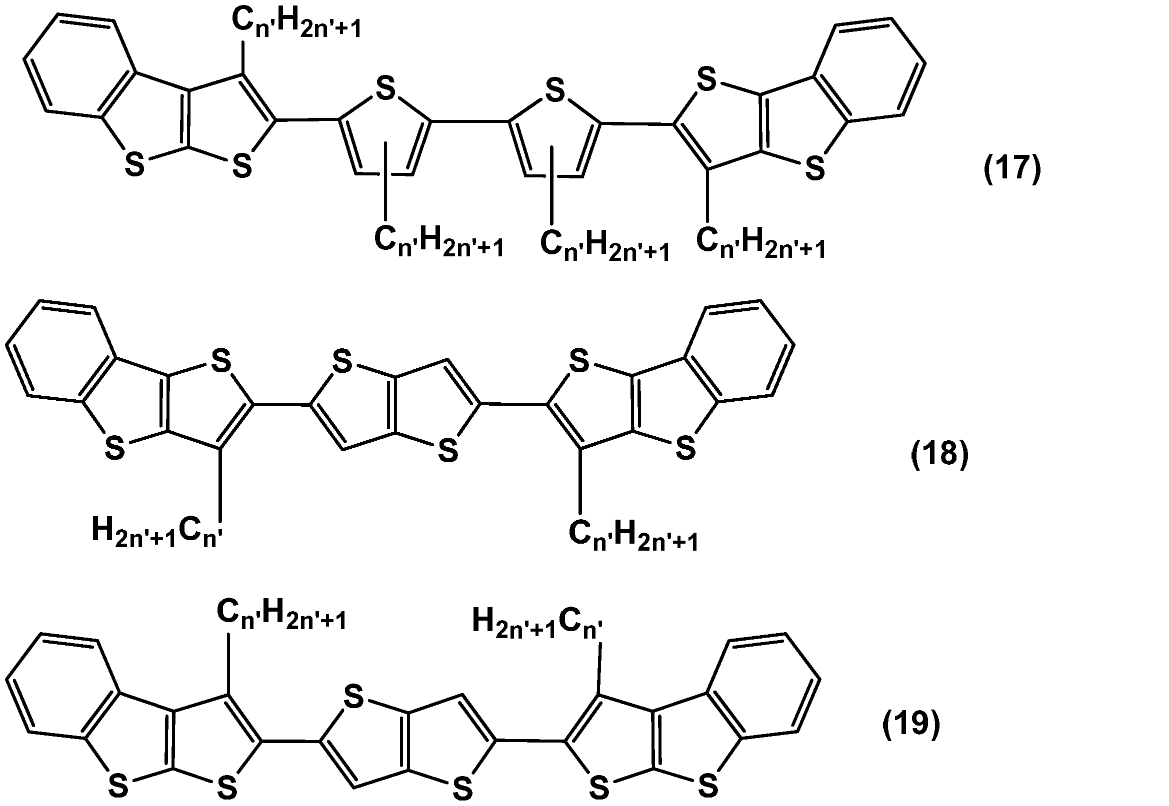


Examples of the aromatic compound represented by the formula (1) include compounds represented by the following formulas (11) to (24). In the formulas (11) to (24), m ′ and n ′ each independently represent an integer of 1 to 20, and preferably an integer of 6 to 12.
次に、上述したような芳香族化合物の製造方法の好適な実施形態について説明する。
Next, a preferred embodiment of the method for producing an aromatic compound as described above will be described.
式(1)で表される芳香族化合物は、例えば、X11及びX12で表される基、すなわち式(1a)及び/又は式(1b)で表される基を形成するための原料化合物と、Ar11で表される基を形成するための原料化合物とをそれぞれ準備した後、これらを反応させることによって得ることができる。以下の説明では、X11及びX12として、代表的な式(1a)で表される基を形成するための方法を例に挙げて説明する。
The aromatic compound represented by the formula (1) is, for example, a raw material compound for forming a group represented by X 11 and X 12, that is, a group represented by the formula (1a) and / or the formula (1b). And a raw material compound for forming a group represented by Ar 11 can be prepared, and then reacted. In the following description, a method for forming a group represented by the typical formula (1a) will be described as an example of X 11 and X 12 .
式(1a)で表される基を形成するための原料化合物としては、下記式(30)で表される化合物が、また、Ar11で表される基を形成するための原料化合物としては、下記式(31)で表される化合物がそれぞれ挙げられる。

As a raw material compound for forming a group represented by the formula (1a), a compound represented by the following formula (30), and as a raw material compound for forming a group represented by Ar 11 , Examples thereof include compounds represented by the following formula (31).
式(30)及び(31)中、R11、R12、Ar11、Ar12、X13及びX14は、いずれも上記と同義である。W0、W1及びW2としては、水素原子、ハロゲン原子、アルキルスルホネート基、アリールスルホネート基、アリールアルキルスルホネート基、アルキルスタニル基、アリールスタニル基、アリールアルキルスタニル基、ホウ酸エステル残基、スルホニウムメチル基、ホスホニウムメチル基、ホスホネートメチル基、モノハロゲン化メチル基、ホウ酸残基(-B(OH)2)、ホルミル基、ビニル基が例示される。なかでも、ハロゲン原子、アルキルスタニル基、ホウ酸エステル残基が好ましい。ホウ酸エステル残基としては、例えば、下記式で示される基が挙げられる。

In formulas (30) and (31), R 11 , R 12 , Ar 11 , Ar 12 , X 13 and X 14 are all as defined above. W 0 , W 1 and W 2 are hydrogen atom, halogen atom, alkylsulfonate group, arylsulfonate group, arylalkylsulfonate group, alkylstannyl group, arylstannyl group, arylalkylstannyl group, boric acid ester residue Group, sulfonium methyl group, phosphonium methyl group, phosphonate methyl group, monohalogenated methyl group, boric acid residue (—B (OH) 2 ), formyl group and vinyl group. Of these, a halogen atom, an alkylstannyl group, and a borate ester residue are preferable. Examples of the boric acid ester residue include a group represented by the following formula.
式(31)で表される化合物の合成がし易く、かつ、原料化合物同士の反応が良好になるので、W1及びW2は、それぞれ独立に、ハロゲン原子、アルキルスルホネート基、アリールスルホネート基、アリールアルキルスルホネート基、ホウ酸エステル残基、ホウ酸残基又はトリアルキルスタニル基であると好ましい。
Since the compound represented by the formula (31) can be easily synthesized and the reaction between the raw material compounds becomes good, W 1 and W 2 are each independently a halogen atom, an alkyl sulfonate group, an aryl sulfonate group, An arylalkyl sulfonate group, a boric acid ester residue, a boric acid residue or a trialkylstannyl group is preferred.
ここで、式(30)で表される原料化合物は、例えば、下記の反応スキームで表される手順で合成することができる。


Here, the raw material compound represented by Formula (30) can be synthesized, for example, according to the procedure represented by the following reaction scheme.
式(I)~(VI)及び式(30)中、R11、R12、Ar12、X13、X14及びW0は、上記と同義であり、X31及びX32は、それぞれ独立に、ハロゲン原子を示す。
In the formulas (I) to (VI) and the formula (30), R 11 , R 12 , Ar 12 , X 13 , X 14 and W 0 are as defined above, and X 31 and X 32 are each independently Represents a halogen atom.
上述したような原料化合物を用いて芳香族化合物を製造する方法としては、例えば、Suzukiカップリング反応を用いる方法、Grignard反応を用いる方法、Stille反応を用いる方法、Ni(0)触媒を用いる方法、FeCl3等の酸化剤を用いる方法、アニオンの酸化反応を用いる方法、酢酸パラジウムと有機塩基を用いる方法、α無置換又はハロゲン体からリチオ体を調製して酸化カップリングする方法、電気化学的な酸化反応を用いる方法、適当な脱離基を有する中間体化合物の分解による方法が挙げられる。これらは、原料化合物や目的とする芳香族化合物の構造等に応じて選択することができる。
Examples of the method for producing an aromatic compound using the raw material compound described above include, for example, a method using a Suzuki coupling reaction, a method using a Grignard reaction, a method using a Stille reaction, a method using a Ni (0) catalyst, A method using an oxidant such as FeCl 3, a method using an anion oxidation reaction, a method using palladium acetate and an organic base, a method of oxidative coupling by preparing an α-unsubstituted or halogenated lithio isomer, and electrochemical Examples thereof include a method using an oxidation reaction and a method by decomposing an intermediate compound having an appropriate leaving group. These can be selected according to the structure of the raw material compound and the target aromatic compound.
これらのなかでも、Suzukiカップリング反応を用いる方法、Grignard反応を用いる方法、Stille反応を用いる方法、Ni(0)触媒を用いる方法、アニオンの酸化反応を用いる方法、酢酸パラジウムと有機塩基を用いる方法が、芳香族化合物の構造を制御し易いこと、原料化合物を入手し易いこと、及び、反応操作を簡便化し易いことから好ましい。
Among these, a method using a Suzuki coupling reaction, a method using a Grignard reaction, a method using a Stille reaction, a method using a Ni (0) catalyst, a method using an anion oxidation reaction, a method using palladium acetate and an organic base However, it is preferable because the structure of the aromatic compound is easily controlled, the raw material compound is easily obtained, and the reaction operation is easily simplified.
Suzukiカップリング反応の場合は、触媒として、例えばパラジウム[テトラキス(トリフェニルホスフィン)]、パラジウムアセテート類を用い、炭酸カリウム、炭酸ナトリウム、水酸化バリウム等の無機塩基、トリエチルアミン等の有機塩基、フッ化セシウム等の無機塩をモノマーに対して当量以上、好ましくは1~10当量加えて、原料化合物を反応させる。また、無機塩を水溶液として、2相系で反応させてもよい。
In the case of the Suzuki coupling reaction, for example, palladium [tetrakis (triphenylphosphine)] or palladium acetate is used as a catalyst, an inorganic base such as potassium carbonate, sodium carbonate, or barium hydroxide, an organic base such as triethylamine, or a fluoride. An inorganic salt such as cesium is added in an amount equal to or greater than the monomer, preferably 1 to 10 equivalents, and the raw material compound is reacted. Moreover, you may make it react by a two-phase system by making inorganic salt into aqueous solution.
この反応に用いる溶媒としては、N,N-ジメチルホルムアミド、トルエン、ジメトキシエタン、テトラヒドロフランが例示される。反応温度は、使用する溶媒にもよるが、50~160℃が好ましい。反応の際には、溶媒の沸点近くまで昇温し、還流させてもよい。好適な反応時間は1~200時間である。このようなSuzukiカップリング反応は、例えば、ケミカル・レビュー(Chem.Rev.),第95巻,2457頁(1995年)に記載された方法に準拠して行うことができる。
Examples of the solvent used in this reaction include N, N-dimethylformamide, toluene, dimethoxyethane, and tetrahydrofuran. The reaction temperature depends on the solvent used, but is preferably 50 to 160 ° C. In the reaction, the temperature may be raised to near the boiling point of the solvent and refluxed. The preferred reaction time is 1 to 200 hours. Such a Suzuki coupling reaction can be performed in accordance with, for example, the method described in Chemical Review (Chem. Rev.), Vol. 95, p. 2457 (1995).
Ni(0)触媒を用いる反応の場合、Ni(0)触媒としてゼロ価ニッケル錯体を使う方法のほか、ニッケル塩を還元剤の存在下で反応させて、系内でゼロ価ニッケルを生成させる方法がある。ゼロ価ニッケル錯体としては、ビス(1,5-シクロオクタジエン)ニッケル(0)、(エチレン)ビス(トリフェニルホスフィン)ニッケル(0)、テトラキス(トリフェニルホスフィン)ニッケルが例示される。なかでも、ビス(1,5-シクロオクタジエン)ニッケル(0)が、汎用性が高く、安価であることから好ましい。
In the case of a reaction using a Ni (0) catalyst, in addition to a method using a zero-valent nickel complex as a Ni (0) catalyst, a method in which a nickel salt is reacted in the presence of a reducing agent to generate zero-valent nickel in the system. There is. Examples of the zerovalent nickel complex include bis (1,5-cyclooctadiene) nickel (0), (ethylene) bis (triphenylphosphine) nickel (0), and tetrakis (triphenylphosphine) nickel. Of these, bis (1,5-cyclooctadiene) nickel (0) is preferred because of its high versatility and low cost.
また、Ni(0)触媒を用いる反応においては、系内に中性配位子を添加すると、収率が向上するためより好ましい。ここで、中性配位子とは、アニオンやカチオンを有していない配位子である。例えば、2,2’-ビピリジル、1,10-フェナントロリン、メチレンビスオキサゾリン、N,N’-テトラメチルエチレンジアミン等の含窒素配位子;トリフェニルホスフィン、トリトリルホスフィン、トリブチルホスフィン、トリフェノキシホスフィン等の第三ホスフィン配位子が挙げられる。なかでも、汎用性が高く、また安価であることから、含窒素配位子が好ましい。特に、2,2’-ビピリジルが、高反応性が得られ、高収率を達成できるため好ましい。より具体的には、芳香族化合物の収率が向上するので、ビス(1,5-シクロオクタジエン)ニッケル(0)を含む系に、中性配位子として2,2’-ビピリジルを加えて反応を行うことが好ましい。
Moreover, in the reaction using a Ni (0) catalyst, it is more preferable to add a neutral ligand to the system because the yield is improved. Here, the neutral ligand is a ligand having no anion or cation. For example, nitrogen-containing ligands such as 2,2′-bipyridyl, 1,10-phenanthroline, methylenebisoxazoline, N, N′-tetramethylethylenediamine; triphenylphosphine, tolylphosphine, tributylphosphine, triphenoxyphosphine, etc. Of the third phosphine ligand. Of these, nitrogen-containing ligands are preferred because they are versatile and inexpensive. In particular, 2,2'-bipyridyl is preferable because high reactivity can be obtained and a high yield can be achieved. More specifically, since the yield of the aromatic compound is improved, 2,2′-bipyridyl is added as a neutral ligand to a system containing bis (1,5-cyclooctadiene) nickel (0). It is preferable to carry out the reaction.
一方、系内でゼロ価ニッケルを生成させる方法の場合、ニッケル塩として塩化ニッケルや酢酸ニッケルを用いることができる。還元剤としては、亜鉛、水素化ナトリウム、ヒドラジン及びその誘導体、リチウムアルミニウムハイドライドが挙げられる。また、必要に応じて、添加物として、ヨウ化アンモニウム、ヨウ化リチウム、ヨウ化カリウム等を併用してもよい。
On the other hand, in the method of generating zero-valent nickel in the system, nickel chloride or nickel acetate can be used as the nickel salt. Examples of the reducing agent include zinc, sodium hydride, hydrazine and derivatives thereof, and lithium aluminum hydride. Moreover, you may use together ammonium iodide, lithium iodide, potassium iodide etc. as an additive as needed.
Stille反応の場合、触媒として、例えば、パラジウム[テトラキス(トリフェニルホスフィン)]やパラジウムアセテート類を用い、有機スズ化合物をモノマーとして用いて反応を行う。この反応に用いる溶媒としては、N,N-ジメチルホルムアミド、トルエン、ジメトキシエタン、テトラヒドロフランが挙げられる。反応温度は、使用する溶媒にもよるが、50~160℃が好ましい。また、溶媒の沸点近くまで昇温して、還流させてもよい。反応時間は1~200時間であると好ましい。
In the Stille reaction, for example, palladium [tetrakis (triphenylphosphine)] or palladium acetate is used as a catalyst, and the reaction is performed using an organic tin compound as a monomer. Examples of the solvent used in this reaction include N, N-dimethylformamide, toluene, dimethoxyethane, and tetrahydrofuran. The reaction temperature depends on the solvent used, but is preferably 50 to 160 ° C. Further, the temperature may be raised to near the boiling point of the solvent and refluxed. The reaction time is preferably 1 to 200 hours.
アニオンの酸化反応を用いる方法の場合、原料化合物等のハロゲン置換体又は水素置換体をモノマーとし、n-ブチルリチウムと反応させてリチオ体を調製して、これを、臭化銅(II)、塩化銅(II)、アセチルアセトナト鉄(III)等の酸化剤で処理する。この反応に用いる溶媒としては、トルエン、ジメトキシエタン、テトラヒドロフラン、ヘキサン、ヘプタン、オクタンが例示される。反応温度は、使用する溶媒にもよるが、50~160℃が好ましい。また、溶媒の沸点近くまで昇温して、還流させてもよい。反応時間は5分~200時間であると好ましい。
In the case of a method using an anion oxidation reaction, a halogen-substituted product or hydrogen-substituted product such as a raw material compound is used as a monomer and reacted with n-butyllithium to prepare a lithiated compound, which is obtained by using copper (II) bromide, Treat with an oxidizing agent such as copper (II) chloride or iron (III) acetylacetonate. Examples of the solvent used in this reaction include toluene, dimethoxyethane, tetrahydrofuran, hexane, heptane, and octane. The reaction temperature depends on the solvent used, but is preferably 50 to 160 ° C. Further, the temperature may be raised to near the boiling point of the solvent and refluxed. The reaction time is preferably 5 minutes to 200 hours.
酢酸パラジウムと有機塩基を用いる方法の場合、ハロゲン置換体をモノマーとして用い、酢酸パラジウム(II)及びジイソプロピルアミン、トリエチルアミンなどの有機塩基を加えて反応を行う。この反応に用いる溶媒としては、N,N-ジメチルホルムアミド、トルエン、ジメトキシエタン、テトラヒドロフランが例示される。反応温度は、使用する溶媒にもよるが、50~160℃が好ましい。また、溶媒の沸点近くまで昇温して、還流させてもよい。反応時間は5分~200時間であると好ましい。
In the method using palladium acetate and an organic base, a halogen-substituted product is used as a monomer, and the reaction is carried out by adding palladium (II) acetate and an organic base such as diisopropylamine or triethylamine. Examples of the solvent used in this reaction include N, N-dimethylformamide, toluene, dimethoxyethane, and tetrahydrofuran. The reaction temperature depends on the solvent used, but is preferably 50 to 160 ° C. Further, the temperature may be raised to near the boiling point of the solvent and refluxed. The reaction time is preferably 5 minutes to 200 hours.
(有機薄膜)
次に、好適な実施形態に係る有機薄膜について説明する。 (Organic thin film)
Next, an organic thin film according to a preferred embodiment will be described.
次に、好適な実施形態に係る有機薄膜について説明する。 (Organic thin film)
Next, an organic thin film according to a preferred embodiment will be described.
好適な実施形態の有機薄膜は、上述した芳香族化合物を含有するものである。なお、有機薄膜は、芳香族化合物の1種類を単独で含むものであってもよく、また芳香族化合物の2種類以上を含むものであってもよい。また、有機薄膜は、電子輸送性又はホール輸送性を高めるために、芳香族化合物以外に、電子輸送性若しくはホール輸送性を有する低分子化合物、又は、上記芳香族化合物とは異なる電子輸送性若しくはホール輸送性を有する高分子化合物(これらの低分子化合物及び高分子化合物を総称して、「電子輸送性材料」、「ホール輸送性材料」という。)を含んでいてもよい。
The organic thin film according to a preferred embodiment contains the above-described aromatic compound. In addition, the organic thin film may contain one kind of aromatic compound independently, and may contain two or more kinds of aromatic compounds. In addition, in order to increase the electron transport property or hole transport property, the organic thin film has a low molecular compound having electron transport property or hole transport property other than the aromatic compound, or an electron transport property different from the aromatic compound or A polymer compound having a hole transport property (these low molecular compounds and polymer compounds are collectively referred to as “electron transport material” and “hole transport material”) may be included.
ホール輸送性材料としては、例えば、ピラゾリン、アリールアミン、スチルベン、トリアリールジアミン、オリゴチオフェン、ポリビニルカルバゾール、ポリシラン、側鎖又は主鎖に芳香族アミンを有するポリシロキサン、ポリアニリン、ポリチオフェン、ポリピロール、ポリアリーレンビニレン、ポリチエニレンビニレン、及びこれらの誘導体が挙げられる。
Examples of the hole transport material include pyrazoline, arylamine, stilbene, triaryldiamine, oligothiophene, polyvinylcarbazole, polysilane, polysiloxane having an aromatic amine in the side chain or main chain, polyaniline, polythiophene, polypyrrole, polyarylene. Examples include vinylene, polythienylene vinylene, and derivatives thereof.
電子輸送性材料としては、例えば、オキサジアゾール、アントラキノジメタン、ベンゾキノン、ナフトキノン、アントラキノン、テトラシアノアンスラキノジメタン、フルオレノン、ジフェニルジシアノエチレン、ジフェノキノン、8-ヒドロキシキノリンの金属錯体、ポリキノリン、ポリキノキサリン、ポリフルオレン、C60等のフラーレン類、及びこれらの誘導体が挙げられる。
Examples of the electron transporting material include oxadiazole, anthraquinodimethane, benzoquinone, naphthoquinone, anthraquinone, tetracyanoanthraquinodimethane, fluorenone, diphenyldicyanoethylene, diphenoquinone, 8-hydroxyquinoline metal complex, polyquinoline, polyquinoline, quinoxaline, polyfluorenes, fullerenes such as C 60, and derivatives thereof.
また、本実施形態の有機薄膜は、有機薄膜中で吸収した光により電荷を発生させるために、電荷発生材料を含んでいてもよい。電荷発生材料としては、例えば、アゾ化合物、ジアゾ化合物、無金属フタロシアニン化合物、金属フタロシアニン化合物、ペリレン化合物、多環キノン系化合物、スクアリリウム化合物、アズレニウム化合物、チアピリリウム化合物及びC60等のフラーレン類が挙げられる。
In addition, the organic thin film of this embodiment may include a charge generation material in order to generate a charge by light absorbed in the organic thin film. Examples of the charge generating material, for example, azo compounds, diazo compounds, metal-free phthalocyanine compounds, metal phthalocyanine compounds, perylene compounds, polycyclic quinone compounds, squarylium compounds, azulenium compounds, fullerenes such thiapyrylium compounds and C 60 and the like .
さらに、有機薄膜は、種々の機能を発現させるために必要な材料を更に含んでいてもよい。このような材料としては、例えば、吸収した光により電荷を発生させる機能を増感するための増感剤、安定性を増すための安定化剤、紫外(UV)光を吸収するためのUV吸収剤が挙げられる。
Furthermore, the organic thin film may further contain materials necessary for developing various functions. Such materials include, for example, a sensitizer for sensitizing the function of generating charge by absorbed light, a stabilizer for increasing stability, and UV absorption for absorbing ultraviolet (UV) light. Agents.
また、有機薄膜は、機械的特性を高めるため、上述した成分で例示した化合物以外の高分子化合物材料を、高分子バインダーとして含んでいてもよい。高分子バインダーとしては、電子輸送性又はホール輸送性を極度に阻害しないものが好ましく、また可視光に対する吸収が強くないものが好ましい。
In addition, the organic thin film may contain a polymer compound material other than the compounds exemplified as the above-described components as a polymer binder in order to improve mechanical properties. As the polymer binder, those that do not extremely inhibit the electron transport property or hole transport property are preferable, and those that do not strongly absorb visible light are preferable.
高分子バインダーとしては、例えば、ポリ(N-ビニルカルバゾール)、ポリアニリン、ポリチオフェン、ポリ(p-フェニレンビニレン)、ポリ(2,5-チエニレンビニレン)、ポリカーボネート、ポリアクリレート、ポリメチルアクリレート、ポリメチルメタクリレート、ポリスチレン、ポリ塩化ビニル、ポリシロキサン、及びこれらの誘導体が挙げられる。
Examples of the polymer binder include poly (N-vinylcarbazole), polyaniline, polythiophene, poly (p-phenylene vinylene), poly (2,5-thienylene vinylene), polycarbonate, polyacrylate, polymethyl acrylate, and polymethyl. Examples include methacrylate, polystyrene, polyvinyl chloride, polysiloxane, and derivatives thereof.
本実施形態の有機薄膜の製造方法としては、例えば、芳香族化合物のほか、必要に応じて混合する電子輸送性材料、ホール輸送性材料、高分子バインダーや溶媒を含む溶液(即ち、組成物)を用いた成膜による方法が挙げられる。また、芳香族化合物が昇華性を有する場合は、真空蒸着法によって有機薄膜を形成することもできる。なお、芳香族化合物を有機薄膜用の材料として用いる場合は、その純度が素子特性に影響を与えることから、有機薄膜の製造前に、昇華精製、再結晶等の方法で純化処理を行ってもよい。
Examples of the method for producing the organic thin film of the present embodiment include, for example, an aromatic compound, an electron transporting material, a hole transporting material, a solution containing a polymer binder and a solvent to be mixed as necessary (that is, a composition). The method by the film-forming using is mentioned. Moreover, when an aromatic compound has sublimability, an organic thin film can also be formed by a vacuum evaporation method. In the case where an aromatic compound is used as a material for an organic thin film, the purity affects the device characteristics. Therefore, even if purification is performed by a method such as sublimation purification or recrystallization before the production of the organic thin film. Good.
溶液による成膜を行う場合、溶液に用いる溶媒としては、芳香族化合物や、混合する電子輸送性材料又はホール輸送性材料、高分子バインダーを溶解させ得るものであればよい。例えば、トルエン、キシレン、メシチレン、テトラリン、デカリン、ビシクロヘキシル、n-ブチルベンゼン、sec-ブチルベンゼン、tert-ブチルベンゼン等の不飽和炭化水素系溶媒、四塩化炭素、クロロホルム、ジクロロメタン、ジクロロエタン、クロロブタン、ブロモブタン、クロロペンタン、ブロモペンタン、クロロヘキサン、ブロモヘキサン、クロロシクロヘキサン、ブロモシクロヘキサン等のハロゲン化飽和炭化水素系溶媒、クロロベンゼン、ジクロロベンゼン、トリクロロベンゼン等のハロゲン化不飽和炭化水素系溶媒、テトラヒドロフラン、テトラヒドロピラン等のエーテル系溶媒を用いることができる。芳香族化合物は、化合物の構造や分子量にもよるが、これらの溶媒に0.1重量%以上溶解させることができる。
In the case of performing film formation using a solution, the solvent used in the solution may be any solvent that can dissolve the aromatic compound, the electron transporting material or hole transporting material to be mixed, and the polymer binder. For example, unsaturated hydrocarbon solvents such as toluene, xylene, mesitylene, tetralin, decalin, bicyclohexyl, n-butylbenzene, sec-butylbenzene, tert-butylbenzene, carbon tetrachloride, chloroform, dichloromethane, dichloroethane, chlorobutane, Halogenated saturated hydrocarbon solvents such as bromobutane, chloropentane, bromopentane, chlorohexane, bromohexane, chlorocyclohexane, bromocyclohexane, halogenated unsaturated hydrocarbon solvents such as chlorobenzene, dichlorobenzene, and trichlorobenzene, tetrahydrofuran, tetrahydro An ether solvent such as pyran can be used. Aromatic compound, depending on the structure and molecular weight of the compound can be dissolved 0.1 by weight% or more in these solvents.
成膜方法としては、スピンコート法、キャスティング法、マイクログラビアコート法、グラビアコート法、バーコート法、ロールコート法、ワイアーバーコート法、ディップコート法、スプレーコート法、スクリーン印刷法、フレキソ印刷法、オフセット印刷法、インクジェット印刷法、ディスペンサー印刷法、ノズルコート法及びキャピラリーコート法等の塗布法を用いることができる。なかでも、スピンコート法、フレキソ印刷法、インクジェット印刷法、ディスペンサー印刷法、ノズルコート法及びキャピラリーコート法が好ましい。
Film formation methods include spin coating, casting, micro gravure coating, gravure coating, bar coating, roll coating, wire bar coating, dip coating, spray coating, screen printing, flexographic printing. Application methods such as offset printing, ink jet printing, dispenser printing, nozzle coating and capillary coating can be used. Of these, spin coating, flexographic printing, ink jet printing, dispenser printing, nozzle coating, and capillary coating are preferred.
有機薄膜の膜厚は、1nm~100μmであることが好ましく、2nm~1000nmであることがより好ましく、5nm~500nmであることがさらに好ましく、20nm~200nmであることが特に好ましい。
The thickness of the organic thin film is preferably 1 nm to 100 μm, more preferably 2 nm to 1000 nm, still more preferably 5 nm to 500 nm, and particularly preferably 20 nm to 200 nm.
また、有機薄膜は、芳香族化合物が配向したものであると、芳香族化合物の主鎖又は側鎖が一方向に並ぶので、更に高い電荷移動度が得られる傾向にある。そのため、有機薄膜を製造する工程には、芳香族化合物を配向させる工程が含まれていてもよい。
Further, when the organic thin film is oriented with an aromatic compound, the main chain or side chain of the aromatic compound is arranged in one direction, so that higher charge mobility tends to be obtained. Therefore, the step of manufacturing the organic thin film may include a step of orienting the aromatic compound.
芳香族化合物を配向させる方法としては、液晶の配向手法として知られている方法を用いることができる。なかでも、ラビング法、光配向法、シェアリング法(ずり応力印加法)や引き上げ塗布法が、配向手法として簡便且つ有用であり利用しやすい傾向にある。特に、ラビング法、シェアリング法が好ましい。
As a method for aligning the aromatic compound, a method known as a liquid crystal alignment method can be used. Among them, the rubbing method, the photo-alignment method, the sharing method (shear stress application method) and the pulling coating method tend to be simple and useful as the alignment method and easy to use. In particular, the rubbing method and the sharing method are preferable.
有機薄膜は、電荷輸送性を有することから、電極から注入された電荷や、光吸収により発生した電荷を輸送制御することができ、その特性により、有機薄膜トランジスタ、有機光電変換素子(有機太陽電池、光センサ等)等の有機薄膜素子に用いることができる。有機薄膜をこれらの有機薄膜素子に用いる場合は、配向処理によって芳香族化合物が配向されていると、より電荷輸送性が向上する傾向にある。
Since the organic thin film has a charge transporting property, it can control the transport of charges injected from the electrodes and the charges generated by light absorption. The organic thin film transistor, the organic photoelectric conversion element (organic solar cell, It can be used for organic thin film elements such as optical sensors. When an organic thin film is used for these organic thin film elements, the charge transporting property tends to be further improved if the aromatic compound is aligned by the alignment treatment.
(有機薄膜素子)
次に、好適な実施形態に係る有機薄膜素子について説明する。上述した芳香族化合物を含む有機薄膜を適用した有機薄膜素子の好適例としては、有機薄膜トランジスタ及び有機光電変換素子が挙げられる。以下、有機薄膜トランジスタ、並びに、有機光電変換素子の例である太陽電池及び光センサについて説明する。 (Organic thin film element)
Next, an organic thin film element according to a preferred embodiment will be described. Preferable examples of the organic thin film element to which the organic thin film containing the aromatic compound described above is applied include an organic thin film transistor and an organic photoelectric conversion element. Hereinafter, a solar cell and an optical sensor which are examples of the organic thin film transistor and the organic photoelectric conversion element will be described.
まず、有機薄膜トランジスタは、例えば、ソース電極及びドレイン電極、これらの間の電流経路となり芳香族化合物を含む有機薄膜からなる活性層(有機薄膜層)、電流経路を通る電流量を制御するゲート電極を備えた構造を有する。このような有機薄膜トランジスタとしては、電界効果型、静電誘導型が例示される。
First, an organic thin film transistor includes, for example, a source electrode and a drain electrode, an active layer (organic thin film layer) made of an organic thin film containing an aromatic compound as a current path between them, and a gate electrode for controlling the amount of current passing through the current path. It has the structure provided. Examples of such an organic thin film transistor include a field effect type and an electrostatic induction type.
電界効果型有機薄膜トランジスタは、ソース電極及びドレイン電極、これらの間の電流経路となり芳香族化合物を含む活性層、電流経路を通る電流量を制御するゲート電極、並びに、活性層とゲート電極との間に配置される絶縁層を備えることが好ましい。特に、ソース電極及びドレイン電極が、芳香族化合物を含む活性層に接して設けられており、さらに活性層に接した絶縁層を挟んでゲート電極が設けられていることが好ましい。
A field-effect organic thin film transistor includes a source electrode and a drain electrode, an active layer containing an aromatic compound as a current path between them, a gate electrode for controlling the amount of current passing through the current path, and between the active layer and the gate electrode. It is preferable to provide an insulating layer disposed on the surface. In particular, the source electrode and the drain electrode are preferably provided in contact with the active layer containing an aromatic compound, and the gate electrode is preferably provided with an insulating layer in contact with the active layer interposed therebetween.
静電誘導型有機薄膜トランジスタは、ソース電極及びドレイン電極、これらの間の電流経路となり芳香族化合物を含有する活性層、並びに電流経路を通る電流量を制御するゲート電極を有しており、ゲート電極が活性層中に設けられていることが好ましい。特に、ソース電極、ドレイン電極及び活性層中に設けられたゲート電極が、芳香族化合物を含有する活性層に接して設けられていることが好ましい。ゲート電極の構造としては、ソース電極からドレイン電極へ流れる電流経路が形成され、かつゲート電極に印加した電圧で電流経路を流れる電流量が制御できる構造であればよく、例えば、くし形電極が挙げられる。
The electrostatic induction type organic thin film transistor has a source electrode and a drain electrode, an active layer that becomes a current path between them and contains an aromatic compound, and a gate electrode that controls an amount of current passing through the current path. Is preferably provided in the active layer. In particular, the source electrode, the drain electrode, and the gate electrode provided in the active layer are preferably provided in contact with the active layer containing the aromatic compound. The structure of the gate electrode may be any structure as long as a current path flowing from the source electrode to the drain electrode is formed and the amount of current flowing through the current path can be controlled by a voltage applied to the gate electrode. It is done.
図1は、第1実施形態に係る有機薄膜トランジスタ(電界効果型有機薄膜トランジスタ)の模式断面図である。図1に示す有機薄膜トランジスタ100は、基板1と、基板1上に所定の間隔を持って形成されたソース電極5及びドレイン電極6と、ソース電極5及びドレイン電極6を覆うようにして基板1上に形成された活性層2と、活性層2上に形成された絶縁層3と、ソース電極5とドレイン電極6との間の絶縁層3の領域を覆うように絶縁層3上に形成されたゲート電極4と、を備えるものである。
FIG. 1 is a schematic cross-sectional view of an organic thin film transistor (field effect organic thin film transistor) according to a first embodiment. An organic thin film transistor 100 shown in FIG. 1 includes a substrate 1, a source electrode 5 and a drain electrode 6 formed on the substrate 1 with a predetermined interval, and a source electrode 5 and a drain electrode 6 so as to cover the substrate 1. Formed on the insulating layer 3 so as to cover the region of the insulating layer 3 between the source electrode 5 and the drain electrode 6, the insulating layer 3 formed on the active layer 2, and the insulating layer 3 formed between the source electrode 5 and the drain electrode 6. And a gate electrode 4.
図2は、第2実施形態に係る有機薄膜トランジスタ(電界効果型有機薄膜トランジスタ)の模式断面図である。図2に示す有機薄膜トランジスタ110は、基板1と、基板1上に形成されたソース電極5と、ソース電極5を覆うようにして基板1上に形成された活性層2と、ソース電極5と所定の間隔を持って活性層2上に形成されたドレイン電極6と、活性層2及びドレイン電極6上に形成された絶縁層3と、ソース電極5とドレイン電極6との間の絶縁層3の領域を覆うように絶縁層3上に形成されたゲート電極4と、を備えるものである。
FIG. 2 is a schematic cross-sectional view of an organic thin film transistor (field effect organic thin film transistor) according to a second embodiment. An organic thin film transistor 110 shown in FIG. 2 includes a substrate 1, a source electrode 5 formed on the substrate 1, an active layer 2 formed on the substrate 1 so as to cover the source electrode 5, a source electrode 5 and a predetermined electrode. Of the drain electrode 6 formed on the active layer 2 with an interval of, the insulating layer 3 formed on the active layer 2 and the drain electrode 6, and the insulating layer 3 between the source electrode 5 and the drain electrode 6. And a gate electrode 4 formed on the insulating layer 3 so as to cover the region.
図3は、第3実施形態に係る有機薄膜トランジスタ(電界効果型有機薄膜トランジスタ)の模式断面図である。図3に示す有機薄膜トランジスタ120は、基板1と、基板1上に形成された活性層2と、活性層2上に所定の間隔を持って形成されたソース電極5及びドレイン電極6と、ソース電極5及びドレイン電極6を一部覆うようにして活性層2上に形成された絶縁層3と、ソース電極5が下部に形成されている絶縁層3の領域とドレイン電極6が下部に形成されている絶縁層3の領域とをそれぞれ一部覆うように、絶縁層3上に形成されたゲート電極4と、を備えるものである。
FIG. 3 is a schematic cross-sectional view of an organic thin film transistor (field effect organic thin film transistor) according to a third embodiment. The organic thin film transistor 120 shown in FIG. 3 includes a substrate 1, an active layer 2 formed on the substrate 1, a source electrode 5 and a drain electrode 6 formed on the active layer 2 with a predetermined interval, and a source electrode. 5 and the drain electrode 6 so as to partially cover the insulating layer 3 formed on the active layer 2, the region of the insulating layer 3 where the source electrode 5 is formed below, and the drain electrode 6 are formed below. And a gate electrode 4 formed on the insulating layer 3 so as to partially cover the region of the insulating layer 3.
図4は、第4実施形態に係る有機薄膜トランジスタ(電界効果型有機薄膜トランジスタ)の模式断面図である。図4に示す有機薄膜トランジスタ130は、基板1と、基板1上に形成されたゲート電極4と、ゲート電極4を覆うようにして基板1上に形成された絶縁層3と、ゲート電極4が下部に形成されている絶縁層3の領域を一部覆うように絶縁層3上に所定の間隔を持って形成されたソース電極5及びドレイン電極6と、ソース電極5及びドレイン電極6を一部覆うように絶縁層3上に形成された活性層2と、を備えるものである。
FIG. 4 is a schematic cross-sectional view of an organic thin film transistor (field effect organic thin film transistor) according to a fourth embodiment. 4 includes a substrate 1, a gate electrode 4 formed on the substrate 1, an insulating layer 3 formed on the substrate 1 so as to cover the gate electrode 4, and the gate electrode 4 at the bottom. The source electrode 5 and the drain electrode 6 formed on the insulating layer 3 at a predetermined interval so as to partially cover the region of the insulating layer 3 formed on the substrate, and the source electrode 5 and the drain electrode 6 are partially covered. Thus, the active layer 2 formed on the insulating layer 3 is provided.
図5は、第5実施形態に係る有機薄膜トランジスタ(電界効果型有機薄膜トランジスタ)の模式断面図である。図5に示す有機薄膜トランジスタ140は、基板1と、基板1上に形成されたゲート電極4と、ゲート電極4を覆うようにして基板1上に形成された絶縁層3と、ゲート電極4が下部に形成されている絶縁層3の領域を一部覆うように絶縁層3上に形成されたソース電極5と、ソース電極5を一部覆うようにして絶縁層3上に形成された活性層2と、ゲート電極4が下部に形成されている活性層2の領域を一部覆うように、ソース電極5と所定の間隔を持って絶縁層3上に形成されたドレイン電極6と、を備えるものである。
FIG. 5 is a schematic cross-sectional view of an organic thin film transistor (field effect organic thin film transistor) according to a fifth embodiment. An organic thin film transistor 140 shown in FIG. 5 includes a substrate 1, a gate electrode 4 formed on the substrate 1, an insulating layer 3 formed on the substrate 1 so as to cover the gate electrode 4, and the gate electrode 4 at the bottom. A source electrode 5 formed on the insulating layer 3 so as to partially cover the region of the insulating layer 3 formed on the active layer 2 and an active layer 2 formed on the insulating layer 3 so as to partially cover the source electrode 5. And a drain electrode 6 formed on the insulating layer 3 at a predetermined interval so as to partially cover the region of the active layer 2 formed below the gate electrode 4 It is.
図6は、第6実施形態に係る有機薄膜トランジスタ(電界効果型有機薄膜トランジスタ)の模式断面図である。図6に示す有機薄膜トランジスタ150は、基板1と、基板1上に形成されたゲート電極4と、ゲート電極4を覆うようにして基板1上に形成された絶縁層3と、ゲート電極4が下部に形成されている絶縁層3の領域を覆うように形成された活性層2と、ゲート電極4が下部に形成されている活性層2の領域を一部覆うように絶縁層3上に形成されたソース電極5と、ゲート電極4が下部に形成されている活性層2の領域を一部覆うように、ソース電極5と所定の間隔を持って絶縁層3上に形成されたドレイン電極6と、を備えるものである。
FIG. 6 is a schematic cross-sectional view of an organic thin film transistor (field effect organic thin film transistor) according to a sixth embodiment. An organic thin film transistor 150 shown in FIG. 6 includes a substrate 1, a gate electrode 4 formed on the substrate 1, an insulating layer 3 formed on the substrate 1 so as to cover the gate electrode 4, and the gate electrode 4 at the bottom. The active layer 2 is formed on the insulating layer 3 so as to partially cover the region of the active layer 2 formed under the active layer 2 and the gate electrode 4 formed below. The source electrode 5 and the drain electrode 6 formed on the insulating layer 3 with a predetermined distance from the source electrode 5 so as to partially cover the region of the active layer 2 where the gate electrode 4 is formed below. , Are provided.
図7は、第7実施形態に係る有機薄膜トランジスタ(静電誘導型有機薄膜トランジスタ)の模式断面図である。図7に示す有機薄膜トランジスタ160は、基板1と、基板1上に形成されたソース電極5と、ソース電極5上に形成された活性層2と、活性層2上に所定の間隔を持って複数形成されたゲート電極4と、ゲート電極4の全てを覆うようにして活性層2上に形成された活性層2a(活性層2aを構成する材料は、活性層2と同一でも異なっていてもよい)と、活性層2a上に形成されたドレイン電極6と、を備えるものである。
FIG. 7 is a schematic cross-sectional view of an organic thin film transistor (static induction organic thin film transistor) according to a seventh embodiment. The organic thin film transistor 160 shown in FIG. 7 includes a substrate 1, a source electrode 5 formed on the substrate 1, an active layer 2 formed on the source electrode 5, and a plurality on the active layer 2 with a predetermined interval. The formed gate electrode 4 and the active layer 2a formed on the active layer 2 so as to cover the gate electrode 4 (the material constituting the active layer 2a may be the same as or different from that of the active layer 2). And a drain electrode 6 formed on the active layer 2a.
第1~第7実施形態に係る有機薄膜トランジスタにおいては、活性層2及び/又は活性層2aは、本発明の芳香族化合物を含有しており、ソース電極5とドレイン電極6の間の電流通路(チャネル)となる。また、ゲート電極4は、電圧を印加することにより活性層2及び/又は活性層2aにおける電流通路(チャネル)を通る電流量を制御する。
In the organic thin film transistors according to the first to seventh embodiments, the active layer 2 and / or the active layer 2a contains the aromatic compound of the present invention, and the current path between the source electrode 5 and the drain electrode 6 ( Channel). The gate electrode 4 controls the amount of current passing through the current path (channel) in the active layer 2 and / or the active layer 2a by applying a voltage.
上述した形態の電界効果型有機薄膜トランジスタは、公知の方法、例えば、特開平5-110069号公報に記載の方法により製造することができる。また、静電誘導型有機薄膜トランジスタは、公知の方法、例えば、特開2004-006476号公報記載の方法により製造することができる。
The field effect organic thin film transistor of the above-described form can be manufactured by a known method, for example, a method described in JP-A-5-110069. The electrostatic induction organic thin film transistor can be produced by a known method, for example, a method described in JP-A-2004-006476.
基板1の材質としては有機薄膜トランジスタとしての特性を阻害しなければよいが、ガラス基板、フレキシブルなフィルム基板及びプラスチック基板を用いることができる。
As a material of the substrate 1, a glass substrate, a flexible film substrate, and a plastic substrate can be used as long as the characteristics as an organic thin film transistor are not impaired.
活性層2を形成する際には、芳香族化合物が有機溶媒に可溶性を有することが、製造上有利であり好ましい。その場合、上記で説明したような、溶液を用いた塗布による有機薄膜の製造方法を適用して、活性層2となる有機薄膜を形成することができる。
When forming the active layer 2, it is advantageous in production and preferable that the aromatic compound is soluble in an organic solvent. In that case, the organic thin film used as the active layer 2 can be formed by applying the manufacturing method of the organic thin film by application | coating using a solution as demonstrated above.
活性層2に接した絶縁層3としては、電気の絶縁性が高い材料であればよく、公知のものを用いることができる。例えば、SiOx、SiNx、Ta2O5、ポリイミド、ポリビニルアルコール、ポリビニルフェノール、有機ガラス及びフォトレジストが挙げられる。低電圧化できるので、絶縁層3は、誘電率の高い材料であることが好ましい。
As the insulating layer 3 in contact with the active layer 2, any material having high electrical insulation may be used, and a known material can be used. For example, SiOx, SiNx, Ta 2 O 5, polyimide, polyvinyl alcohol, polyvinyl phenol, organic glass and photoresists. Since the voltage can be lowered, the insulating layer 3 is preferably a material having a high dielectric constant.
絶縁層3の上に活性層2を形成する場合は、絶縁層3と活性層2の界面特性を改善するために、絶縁層3の表面をシランカップリング剤等の表面処理剤で処理して表面の改質を行った後に、活性層2を形成することも可能である。表面処理剤としては、例えば、長鎖アルキルクロロシラン類、長鎖アルキルアルコキシシラン類、フッ素化アルキルクロロシラン類、フッ素化アルキルアルコキシシラン類、ヘキサメチルジシラザン等のシリルアミン化合物が挙げられる。表面処理剤で処理する前には、絶縁層3の表面をオゾンUVやO2プラズマで処理しておくことも可能である。
When forming the active layer 2 on the insulating layer 3, in order to improve the interface characteristics between the insulating layer 3 and the active layer 2, the surface of the insulating layer 3 is treated with a surface treatment agent such as a silane coupling agent. It is also possible to form the active layer 2 after surface modification. Examples of the surface treatment agent include silylamine compounds such as long-chain alkylchlorosilanes, long-chain alkylalkoxysilanes, fluorinated alkylchlorosilanes, fluorinated alkylalkoxysilanes, and hexamethyldisilazane. Prior to the treatment with the surface treatment agent, the surface of the insulating layer 3 can be treated with ozone UV or O 2 plasma.
また、有機薄膜トランジスタを作製した後には、素子を保護するために、有機薄膜トランジスタ上に保護膜を形成することが好ましい。これにより、有機薄膜トランジスタを大気から遮断することができ、有機薄膜トランジスタの特性の低下を抑えることが可能となる。また、有機薄膜トランジスタの上に駆動する表示デバイスを形成する場合に、保護膜によって、表示デバイスの製造工程による有機薄膜トランジスタへの影響を低減することができる。
In addition, after manufacturing the organic thin film transistor, it is preferable to form a protective film on the organic thin film transistor in order to protect the element. Thereby, an organic thin-film transistor can be interrupted | blocked from air | atmosphere, and it becomes possible to suppress the fall of the characteristic of an organic thin-film transistor. Moreover, when forming the display device driven on an organic thin-film transistor, the influence on the organic thin-film transistor by the manufacturing process of a display device can be reduced with a protective film.
保護膜を形成する方法としては、例えば、有機薄膜トランジスタを、UV硬化樹脂、熱硬化樹脂又は無機のSiONx膜でカバーする方法が挙げられる。大気との遮断を効果的に行うためには、有機薄膜トランジスタを作製してから保護膜を形成するまでの工程を、大気に曝すことなく(例えば、乾燥した窒素雰囲気中、真空中で)行うことが好ましい。
Examples of the method for forming the protective film include a method of covering the organic thin film transistor with a UV curable resin, a thermosetting resin, or an inorganic SiONx film. In order to effectively shut off from the atmosphere, the steps from the preparation of the organic thin film transistor to the formation of the protective film are performed without exposure to the atmosphere (for example, in a dry nitrogen atmosphere or in a vacuum). Is preferred.
次に、有機光電変換素子の好適な実施形態について説明する。有機光電変換素子の代表的なものとしては、上記のように、太陽電池や光センサがある。
Next, a preferred embodiment of the organic photoelectric conversion element will be described. Typical examples of the organic photoelectric conversion element include a solar cell and an optical sensor as described above.
図8は、好適な実施形態の太陽電池を示す模式断面図である。図8に示す太陽電池200は、基板1と、基板1上に形成された第1の電極7aと、第1の電極7a上に形成された芳香族化合物を含有する有機薄膜からなる活性層2と、活性層2上に形成された第2の電極7bと、を備えるものである。
FIG. 8 is a schematic cross-sectional view showing a solar cell according to a preferred embodiment. The solar cell 200 shown in FIG. 8 includes an active layer 2 made of a substrate 1, a first electrode 7a formed on the substrate 1, and an organic thin film containing an aromatic compound formed on the first electrode 7a. And a second electrode 7 b formed on the active layer 2.
太陽電池200においては、第1の電極7a及び第2の電極7bの一方に透明又は半透明の電極を用いる。電極材料としては、アルミニウム、金、銀、銅、アルカリ金属、アルカリ土類金属等の金属や、それらの半透明膜、透明導電膜を用いることができる。電極材料は、高い開放電圧を得るために、第1の電極7aと第2の電極7bとの仕事関数の差が大きくなるように選ばれることが好ましい。また、活性層2中には光感度を高めるために電荷発生剤、増感剤等を添加してもよい。基材1としては、シリコン基板、ガラス基板、プラスチック基板等を用いることができる。
In the solar cell 200, a transparent or translucent electrode is used for one of the first electrode 7a and the second electrode 7b. As an electrode material, metals such as aluminum, gold, silver, copper, alkali metal, alkaline earth metal, and semi-transparent films and transparent conductive films thereof can be used. The electrode material is preferably selected so that the work function difference between the first electrode 7a and the second electrode 7b is large in order to obtain a high open circuit voltage. In addition, a charge generating agent, a sensitizer, or the like may be added to the active layer 2 in order to increase photosensitivity. As the substrate 1, a silicon substrate, a glass substrate, a plastic substrate, or the like can be used.
図9は、第1実施形態に係る光センサを示す模式断面図である。図9に示す光センサ300は、基板1と、基板1上に形成された第1の電極7aと、第1の電極7a上に形成された芳香族化合物を含有する有機薄膜からなる活性層2と、活性層2上に形成された電荷発生層8と、電荷発生層8上に形成された第2の電極7bと、を備えるものである。
FIG. 9 is a schematic cross-sectional view showing the photosensor according to the first embodiment. An optical sensor 300 shown in FIG. 9 includes an active layer 2 made of a substrate 1, a first electrode 7a formed on the substrate 1, and an organic thin film containing an aromatic compound formed on the first electrode 7a. And a charge generation layer 8 formed on the active layer 2 and a second electrode 7b formed on the charge generation layer 8.
また、図10は、第2実施形態に係る光センサの模式断面図である。図10に示す光センサ310は、基板1と、基板1上に形成された第1の電極7aと、第1の電極7a上に形成された電荷発生層8と、電荷発生層8上に形成された芳香族化合物を含有する有機薄膜からなる活性層2と、活性層2上に形成された第2の電極7bと、を備えるものである。
FIG. 10 is a schematic cross-sectional view of an optical sensor according to the second embodiment. An optical sensor 310 illustrated in FIG. 10 is formed on the substrate 1, the first electrode 7a formed on the substrate 1, the charge generation layer 8 formed on the first electrode 7a, and the charge generation layer 8. And an active layer 2 made of an organic thin film containing an aromatic compound, and a second electrode 7b formed on the active layer 2.
さらに、図11は、第3実施形態に係る光センサの模式断面図である。図11に示す光センサ320は、基板1と、基板1上に形成された第1の電極7aと、第1の電極7a上に形成された芳香族化合物を含有する有機薄膜からなる活性層2と、活性層2上に形成された第2の電極7bと、を備えるものである。
Furthermore, FIG. 11 is a schematic cross-sectional view of an optical sensor according to the third embodiment. An optical sensor 320 shown in FIG. 11 includes an active layer 2 made of an organic thin film containing a substrate 1, a first electrode 7a formed on the substrate 1, and an aromatic compound formed on the first electrode 7a. And a second electrode 7 b formed on the active layer 2.
第1~第3実施形態に係る光センサにおいては、第1の電極7a及び第2の電極7bの一方に透明又は半透明の電極を用いる。電極材料としては、アルミニウム、金、銀、銅、アルカリ金属、アルカリ土類金属等の金属及びそれらの半透明膜、透明導電膜を用いることができる。電荷発生層8は光を吸収して電荷を発生する層である。また、活性層2中には、光感度を高めるためにキャリア発生剤、増感剤等を添加してもよい。さらに、基材1としては、シリコン基板、ガラス基板、プラスチック基板等を用いることができる。
In the optical sensors according to the first to third embodiments, a transparent or translucent electrode is used as one of the first electrode 7a and the second electrode 7b. As an electrode material, metals such as aluminum, gold, silver, copper, alkali metal, alkaline earth metal, and their translucent films and transparent conductive films can be used. The charge generation layer 8 is a layer that absorbs light and generates charges. In addition, a carrier generating agent, a sensitizer, or the like may be added to the active layer 2 in order to increase photosensitivity. Furthermore, as the base material 1, a silicon substrate, a glass substrate, a plastic substrate, etc. can be used.
以上、本発明をその実施形態に基づいて詳細に説明したが、本発明は上記の実施形態に限定されるものではなく、本発明の要旨を逸脱しない範囲で様々な変形が可能である。
As mentioned above, although this invention was demonstrated in detail based on the embodiment, this invention is not limited to said embodiment, A various deformation | transformation is possible in the range which does not deviate from the summary of this invention.
以下、本発明を実施例により更に具体的に説明するが、本発明はこれらの実施例に限定されるものではない。
Hereinafter, the present invention will be described more specifically with reference to examples, but the present invention is not limited to these examples.
[測定条件]
以下の合成例及び実施例において行った各種の分析等の条件を示す。すなわち、まず、核磁気共鳴(NMR)スペクトルは、日本電子社製のJNM-GSX-400を用いて測定した。カラムクロマトグラフィー分離におけるシリカゲルは、和光純薬工業社製のワコーゲルC-200を用いた。 [Measurement condition]
Conditions for various analyzes and the like performed in the following synthesis examples and examples are shown. That is, first, nuclear magnetic resonance (NMR) spectrum was measured using JNM-GSX-400 manufactured by JEOL. Wako Gel C-200 manufactured by Wako Pure Chemical Industries, Ltd. was used as the silica gel in the column chromatography separation.
サイクリックボルタンメトリーは、測定装置としてビー・エー・エス株式会社(BAS社)製の商品名「CV-50W」を使用し、作用電極としてBAS社製Pt電極、対電極としてPt線、参照電極としてAg線を用いて測定した。この測定時の掃引速度は100mV/秒、走査電位領域は0~1.2Vであった。酸化電位は、化合物を3×10-3mol/L、支持電解質としてテトラブチルアンモニウムヘキサフルオロホスファート(TBAPF6)0.1mol/Lをジクロロメタン溶媒に完全に溶解させて測定した。
Cyclic voltammetry uses the product name “CV-50W” manufactured by BAS Co., Ltd. (BAS) as a measuring device, a Pt electrode manufactured by BAS as a working electrode, a Pt wire as a counter electrode, and a reference electrode It measured using the Ag line. During this measurement, the sweep speed was 100 mV / second, and the scanning potential region was 0 to 1.2V. The oxidation potential was measured by completely dissolving 3 × 10 −3 mol / L of the compound and 0.1 mol / L of tetrabutylammonium hexafluorophosphate (TBAPF6) as a supporting electrolyte in a dichloromethane solvent.
酸化電位(E1/2ox)は、酸化波の立ち上がり電位として求めた。HOMO(最高被占有分子軌道)レベルはフェロセンを内部標準(酸化電位-0.21V、真空準位から4.8eV)とした第1酸化電位より求めた。紫外(UV)吸収スペクトルは、測定装置として島津製作所社製の商品名「UV-2500PC」を用い、化合物をクロロホルムに5×10-6Mの濃度に溶解させて測定した。エネルギーバンドギャップはUV吸収端波長により求めた。
The oxidation potential (E 1/2 ox) was determined as the rising potential of the oxidation wave. The HOMO (maximum occupied molecular orbital) level was determined from the first oxidation potential with ferrocene as an internal standard (oxidation potential -0.21 V, 4.8 eV from the vacuum level). The ultraviolet (UV) absorption spectrum was measured by using a trade name “UV-2500PC” manufactured by Shimadzu Corporation as a measuring apparatus and dissolving the compound in chloroform at a concentration of 5 × 10 −6 M. The energy band gap was determined from the UV absorption edge wavelength.
イオン化ポテンシャルは、理研計器株式会社製大気中光電子分光装置(AC-2)を用いて、照射光エネルギー-(光電子放出数)1/2の関係をプロットし、光電子放出数が立ち上がる照射光エネルギーとして求めた。
For the ionization potential, use the atmospheric photoelectron spectrometer (AC-2) manufactured by Riken Keiki Co., Ltd., and plot the relationship between irradiation light energy and (photoelectron emission number) 1/2. Asked.
[芳香族化合物の合成]
<実施例1>
(合成例1:3-クロロ-N-メトキシ-N-メチルベンゾ[b]チオフェン-2-カルボキサミドの合成)
まず、出発原料である3-クロロベンゾ[b]チオフェン-2-カルボニルクロリドを、参考文献(T.Higa,A.J.Krubsack,J.Org.Chem., 1975,21,3037)の記載を参照して合成した。 [Synthesis of aromatic compounds]
<Example 1>
Synthesis Example 1: Synthesis of 3-chloro-N-methoxy-N-methylbenzo [b] thiophene-2-carboxamide
First, the starting material 3-chlorobenzo [b] thiophene-2-carbonyl chloride is referred to the description in the reference (T. Higa, AJ Krubsack, J. Org. Chem., 1975, 21, 3037). And synthesized.
次いで、これを用いて、3-クロロ-N-メトキシ-N-メチルベンゾ[b]チオフェン-2-カルボキサミドを合成した。すなわち、まず、50mLのナスフラスコに、上記で得た3-クロロベンゾ[b]チオフェン-2-カルボニルクロリドを462mg(2.0mmol)、N,O-ジメチルヒドロキシルアミン塩酸塩を215mL(2.2mmol)、トリエチルアミンを489mg(4.8mmol)、ジクロロメタンを10mL、それぞれ加えて、それらを室温で4時間攪拌した。
This was then used to synthesize 3-chloro-N-methoxy-N-methylbenzo [b] thiophene-2-carboxamide. Specifically, first, 462 mg (2.0 mmol) of 3-chlorobenzo [b] thiophene-2-carbonyl chloride obtained above and 215 mL (2.2 mmol) of N, O-dimethylhydroxylamine hydrochloride were added to a 50 mL eggplant flask. , 489 mg (4.8 mmol) of triethylamine and 10 mL of dichloromethane were added respectively, and they were stirred at room temperature for 4 hours.
反応後の溶液をエーテルで抽出し、硫酸ナトリウムで乾燥させた後、溶媒を留去した。その後、酢酸エチルを3重量%含むヘキサンを展開溶媒とするシリカゲルカラムクロマトグラフィーにより精製し、目的とする3-クロロ-N-メトキシ-N-メチルベンゾ[b]チオフェン-2-カルボキサミド(下記式(A)で表される化合物A)を、黄白色固体(388mg、収率76%)の状態で得た。
The solution after the reaction was extracted with ether and dried over sodium sulfate, and then the solvent was distilled off. Thereafter, the product was purified by silica gel column chromatography using hexane containing 3% by weight of ethyl acetate as a developing solvent, and the desired 3-chloro-N-methoxy-N-methylbenzo [b] thiophene-2-carboxamide (formula (A ) Was obtained in the form of a pale yellow solid (388 mg, yield 76%).
得られた目的物の1H-NMRの測定結果は以下の通りであった。
1H-NMR(400MHz,CDCl3);δ(ppm)=7.97-7.91(m,1H),7.84-7.79(m,1H),7.52-7.46(m,2H),3.72(s,3H),3.40(s,3H)

1 H-NMR measurement results of the obtained target product were as follows.
1 H-NMR (400 MHz, CDCl 3 ); δ (ppm) = 7.97-7.91 (m, 1H), 7.84-7.79 (m, 1H), 7.52-7.46 ( m, 2H), 3.72 (s, 3H), 3.40 (s, 3H)
1H-NMR(400MHz,CDCl3);δ(ppm)=7.97-7.91(m,1H),7.84-7.79(m,1H),7.52-7.46(m,2H),3.72(s,3H),3.40(s,3H)
1 H-NMR (400 MHz, CDCl 3 ); δ (ppm) = 7.97-7.91 (m, 1H), 7.84-7.79 (m, 1H), 7.52-7.46 ( m, 2H), 3.72 (s, 3H), 3.40 (s, 3H)
(合成例2:1-(3-クロロベンゾ[b]チオフェン-2-イル)トリデカン-1-オンの合成)
20mLの反応器に、上記で得られた化合物Aを300mg(1.2mmol)、及びテトラヒドロフラン(THF)を5mLそれぞれ加え、これにn-ドデシルマグネシウムブロミドのTHF溶液(0.50M)を12mL(6.0mmol)、シリンジを用いて注入し、室温で2時間攪拌した。 (Synthesis Example 2: Synthesis of 1- (3-chlorobenzo [b] thiophen-2-yl) tridecan-1-one)
To a 20 mL reactor, 300 mg (1.2 mmol) of the compound A obtained above and 5 mL of tetrahydrofuran (THF) were added, respectively. To this, 12 mL (6 mL) of a THF solution (0.50 M) of n-dodecylmagnesium bromide was added. 0.0 mmol), was injected using a syringe and stirred at room temperature for 2 hours.
反応後の溶液に希塩酸を注入して反応を終了させた後、酢酸エチルで抽出し、さらに硫酸ナトリウムで乾燥させてから溶媒を留去した。その後、得られた反応物を、酢酸エチルを1重量%含むヘキサンを展開溶媒とするシリカゲルカラムクロマトグラフィーによって精製することにより、目的とする1-(3-クロロベンゾ[b]チオフェン-2-イル)トリデカン-1-オン(下記式(B)で表される化合物B)を、黄白色固体(213mg,収率49%)の状態で得た。
Dilute hydrochloric acid was poured into the solution after the reaction to terminate the reaction, followed by extraction with ethyl acetate and further drying with sodium sulfate, and then the solvent was distilled off. Thereafter, the obtained reaction product is purified by silica gel column chromatography using hexane containing 1% by weight of ethyl acetate as a developing solvent to obtain the target 1- (3-chlorobenzo [b] thiophen-2-yl). Tridecan-1-one (Compound B represented by the following formula (B)) was obtained in the form of a yellowish white solid (213 mg, yield 49%).
得られた目的物の1H-NMRの測定結果は以下の通りであった。
1H-NMR(400MHz,CDCl3);δ(ppm)=7.97(d,J=8.0Hz,1H),7.82(d,J=6.8Hz,1H),7.55-7.46(m,2H),3.15(t,J=7.2Hz,2H),1.84-1.72(m,2H),1.46-1.20(m,18H),0.88(t,J=7.6Hz,3H)

1 H-NMR measurement results of the obtained target product were as follows.
1 H-NMR (400 MHz, CDCl 3 ); δ (ppm) = 7.97 (d, J = 8.0 Hz, 1H), 7.82 (d, J = 6.8 Hz, 1H), 7.55- 7.46 (m, 2H), 3.15 (t, J = 7.2 Hz, 2H), 1.84-1.72 (m, 2H), 1.46-1.20 (m, 18H), 0.88 (t, J = 7.6 Hz, 3H)
1H-NMR(400MHz,CDCl3);δ(ppm)=7.97(d,J=8.0Hz,1H),7.82(d,J=6.8Hz,1H),7.55-7.46(m,2H),3.15(t,J=7.2Hz,2H),1.84-1.72(m,2H),1.46-1.20(m,18H),0.88(t,J=7.6Hz,3H)
1 H-NMR (400 MHz, CDCl 3 ); δ (ppm) = 7.97 (d, J = 8.0 Hz, 1H), 7.82 (d, J = 6.8 Hz, 1H), 7.55- 7.46 (m, 2H), 3.15 (t, J = 7.2 Hz, 2H), 1.84-1.72 (m, 2H), 1.46-1.20 (m, 18H), 0.88 (t, J = 7.6 Hz, 3H)
(合成例3:3-ドデシルベンゾ[4,5]チエノ[3,2-b]-2-チオフェンカルボン酸エチルの合成)
20mLの反応器に、上記で得られた化合物Bを213mg(0.58mmol)、チオグリコール酸エチルを77.0mg(0.64mmol)、炭酸カリウムを160mg(1.16mmol)、N,N-ジメチルホルムアミド(DMF)を3mL、それぞれ加え、これらを室温で18時間攪拌した。その後、水酸化ナトリウムのエタノール溶液(0.5M,0.4mL)を加えて、さらに2時間攪拌した。 Synthesis Example 3: Synthesis of ethyl 3-dodecylbenzo [4,5] thieno [3,2-b] -2-thiophenecarboxylate
In a 20 mL reactor, 213 mg (0.58 mmol) of the compound B obtained above, 77.0 mg (0.64 mmol) of ethyl thioglycolate, 160 mg (1.16 mmol) of potassium carbonate, N, N-dimethyl 3 mL of formamide (DMF) was added respectively, and these were stirred at room temperature for 18 hours. Thereafter, an ethanol solution of sodium hydroxide (0.5 M, 0.4 mL) was added, and the mixture was further stirred for 2 hours.
20mLの反応器に、上記で得られた化合物Bを213mg(0.58mmol)、チオグリコール酸エチルを77.0mg(0.64mmol)、炭酸カリウムを160mg(1.16mmol)、N,N-ジメチルホルムアミド(DMF)を3mL、それぞれ加え、これらを室温で18時間攪拌した。その後、水酸化ナトリウムのエタノール溶液(0.5M,0.4mL)を加えて、さらに2時間攪拌した。 Synthesis Example 3: Synthesis of ethyl 3-dodecylbenzo [4,5] thieno [3,2-b] -2-thiophenecarboxylate
In a 20 mL reactor, 213 mg (0.58 mmol) of the compound B obtained above, 77.0 mg (0.64 mmol) of ethyl thioglycolate, 160 mg (1.16 mmol) of potassium carbonate, N, N-
この反応後の溶液をエーテルで抽出し、硫酸ナトリウムで乾燥させた後、溶媒を留去した。その後、得られた反応液を、酢酸エチルを0.5重量%含むヘキサンを展開溶媒とするシリカゲルカラムクロマトグラフィーで精製することにより、目的とする3-ドデシルベンゾ[4,5]チエノ[3,2-b]-2-チオフェンカルボン酸エチル(下記式(C)で表される化合物C)を、黄色固体(224mg,収率90%)の状態で得た。
The solution after this reaction was extracted with ether and dried over sodium sulfate, and then the solvent was distilled off. Thereafter, the obtained reaction solution is purified by silica gel column chromatography using hexane containing 0.5% by weight of ethyl acetate as a developing solvent, whereby the desired 3-dodecylbenzo [4,5] thieno [3, 2-b] -ethyl 2-thiophenecarboxylate (compound C represented by the following formula (C)) was obtained in the form of a yellow solid (224 mg, yield 90%).
得られた目的物の1H-NMRの測定結果は以下の通りであった。
1H-NMR(400MHz,CDCl3);δ(ppm)=7.90-7.84(m,2H),7.46-7.38(m,2H),4.39(q,J=7.2Hz,2H),3.18(t,J=8.0Hz,2H),1.80-1.70(m,2H),1.46-1.20(m,21H),0.88(t,J=7.2Hz,3H)

1 H-NMR measurement results of the obtained target product were as follows.
1 H-NMR (400 MHz, CDCl 3 ); δ (ppm) = 7.90-7.84 (m, 2H), 7.46-7.38 (m, 2H), 4.39 (q, J = 7.2 Hz, 2H), 3.18 (t, J = 8.0 Hz, 2H), 1.80-1.70 (m, 2H), 1.46-1.20 (m, 21H),. 88 (t, J = 7.2Hz, 3H)
1H-NMR(400MHz,CDCl3);δ(ppm)=7.90-7.84(m,2H),7.46-7.38(m,2H),4.39(q,J=7.2Hz,2H),3.18(t,J=8.0Hz,2H),1.80-1.70(m,2H),1.46-1.20(m,21H),0.88(t,J=7.2Hz,3H)
1 H-NMR (400 MHz, CDCl 3 ); δ (ppm) = 7.90-7.84 (m, 2H), 7.46-7.38 (m, 2H), 4.39 (q, J = 7.2 Hz, 2H), 3.18 (t, J = 8.0 Hz, 2H), 1.80-1.70 (m, 2H), 1.46-1.20 (m, 21H),. 88 (t, J = 7.2Hz, 3H)
(合成例4:3-ドデシルベンゾ[4,5]チエノ[3,2-b]-2-チオフェンカルボン酸の合成)
100mLのナスフラスコに、上記で得られた化合物Cを294mg(0.68mmol)、水酸化カリウムを114mg(2.04mmol)、水を1mL、エタノールを5mL、それぞれ加えて、100℃で8時間攪拌した。 Synthesis Example 4: Synthesis of 3-dodecylbenzo [4,5] thieno [3,2-b] -2-thiophenecarboxylic acid
To a 100 mL eggplant flask, 294 mg (0.68 mmol) of Compound C obtained above, 114 mg (2.04 mmol) of potassium hydroxide, 1 mL of water and 5 mL of ethanol were added, and the mixture was stirred at 100 ° C. for 8 hours. did.
この反応後の溶液からエタノールを留去した後、希塩酸を加えて析出した固体を、吸引ろ過によって分離して、目的とする3-ドデシルベンゾ[4,5]チエノ[3,2-b]-2-チオフェンカルボン酸(下記式(D)で表される化合物D)を、白色固体(240mg,収率88%)として得た。
After distilling off ethanol from the solution after this reaction, dilute hydrochloric acid was added and the precipitated solid was separated by suction filtration to obtain the desired 3-dodecylbenzo [4,5] thieno [3,2-b]- 2-thiophenecarboxylic acid (Compound D represented by the following formula (D)) was obtained as a white solid (240 mg, yield 88%).
得られた目的物の1H-NMRの測定結果は以下の通りであった。
1H-NMR(400MHz,CDCl3);δ(ppm)=7.94-7.89(m,1H),7.89-7.84(m,1H),7.48-7.40(m,2H),3.23(t,J=7.6Hz,2H),1.85-1.74(m,2H),1.46-1.20(m,18H),0.87(t,J=7.2Hz,3H)

1 H-NMR measurement results of the obtained target product were as follows.
1 H-NMR (400 MHz, CDCl 3 ); δ (ppm) = 7.94-7.89 (m, 1H), 7.89-7.84 (m, 1H), 7.48-7.40 ( m, 2H), 3.23 (t, J = 7.6 Hz, 2H), 1.85-1.74 (m, 2H), 1.46-1.20 (m, 18H), 0.87 ( t, J = 7.2 Hz, 3H)
1H-NMR(400MHz,CDCl3);δ(ppm)=7.94-7.89(m,1H),7.89-7.84(m,1H),7.48-7.40(m,2H),3.23(t,J=7.6Hz,2H),1.85-1.74(m,2H),1.46-1.20(m,18H),0.87(t,J=7.2Hz,3H)
1 H-NMR (400 MHz, CDCl 3 ); δ (ppm) = 7.94-7.89 (m, 1H), 7.89-7.84 (m, 1H), 7.48-7.40 ( m, 2H), 3.23 (t, J = 7.6 Hz, 2H), 1.85-1.74 (m, 2H), 1.46-1.20 (m, 18H), 0.87 ( t, J = 7.2 Hz, 3H)
(合成例5:3-ドデシルベンゾ[4,5]チエノ[3,2-b]チオフェンの合成)
50mLのナスフラスコに、上記で得られた化合物Dを220mg(0.55mmol)、銅粉を35mg(0.55mmol)、キノリンを3.5mLそれぞれ加え、これらを窒素雰囲気下、260℃で4時間撹拌した。 (Synthesis Example 5: Synthesis of 3-dodecylbenzo [4,5] thieno [3,2-b] thiophene)
To a 50 mL eggplant flask, 220 mg (0.55 mmol) of the compound D obtained above, 35 mg (0.55 mmol) of copper powder, and 3.5 mL of quinoline were added, and these were added at 260 ° C. for 4 hours under a nitrogen atmosphere. Stir.
この反応後の溶液をエーテルで抽出した後、有機層を硫酸ナトリウムで乾燥させ、更に溶媒を留去した。得られた残存物を、ヘキサンを展開溶媒とするシリカゲルカラムクロマトグラフィーで精製することにより、目的とする3-ドデシルベンゾ[4,5]チエノ[3,2-b]チオフェン(下記式(E)で表される化合物E)を、黄白色固体(192mg,収率98%)として得た。
The solution after this reaction was extracted with ether, the organic layer was dried over sodium sulfate, and the solvent was distilled off. The obtained residue is purified by silica gel column chromatography using hexane as a developing solvent to obtain the desired 3-dodecylbenzo [4,5] thieno [3,2-b] thiophene (the following formula (E) Was obtained as a pale yellow solid (192 mg, yield 98%).
得られた目的物の1H-NMRの測定結果は以下の通りであった。
1H-NMR(400MHz,CDCl3);δ(ppm)=7.84(d,J=8.4Hz,1H),7.82(d,J=7.6Hz,1H),7.09(s,1H),2.75(t,J=8.0Hz,2H),1.82-1.71(m,2H),1.46-1.20(m,18H),0.88(t,J=6.8Hz,3H)

1 H-NMR measurement results of the obtained target product were as follows.
1 H-NMR (400 MHz, CDCl 3 ); δ (ppm) = 7.84 (d, J = 8.4 Hz, 1H), 7.82 (d, J = 7.6 Hz, 1H), 7.09 ( s, 1H), 2.75 (t, J = 8.0 Hz, 2H), 1.82-1.71 (m, 2H), 1.46-1.20 (m, 18H), 0.88 ( t, J = 6.8 Hz, 3H)
1H-NMR(400MHz,CDCl3);δ(ppm)=7.84(d,J=8.4Hz,1H),7.82(d,J=7.6Hz,1H),7.09(s,1H),2.75(t,J=8.0Hz,2H),1.82-1.71(m,2H),1.46-1.20(m,18H),0.88(t,J=6.8Hz,3H)
1 H-NMR (400 MHz, CDCl 3 ); δ (ppm) = 7.84 (d, J = 8.4 Hz, 1H), 7.82 (d, J = 7.6 Hz, 1H), 7.09 ( s, 1H), 2.75 (t, J = 8.0 Hz, 2H), 1.82-1.71 (m, 2H), 1.46-1.20 (m, 18H), 0.88 ( t, J = 6.8 Hz, 3H)
(合成例6:2-ブロモ-3-ドデシルベンゾ[4,5]チエノ[3,2-b]チオフェンの合成)
100mLのナスフラスコに、上記で得られた化合物Eを192mg(0.54mmol)、N-ブロモスクシンイミド(NBS)を127mg(0.72mmol)、DMFを5mLそれぞれ加え、室温で5時間攪拌した。 (Synthesis Example 6: Synthesis of 2-bromo-3-dodecylbenzo [4,5] thieno [3,2-b] thiophene)
To a 100 mL eggplant flask, 192 mg (0.54 mmol) of the compound E obtained above, 127 mg (0.72 mmol) of N-bromosuccinimide (NBS), and 5 mL of DMF were added and stirred at room temperature for 5 hours.
この反応後の溶液をエーテルで抽出した後、有機層を取り出し、これを硫酸ナトリウムで乾燥させた。その後、溶媒を留去して得られた残存物を、ヘキサンを展開溶媒とするシリカゲルカラムクロマトグラフィーで精製して、目的とする2-ブロモ-3-ドデシルベンゾ[4,5]チエノ[3,2-b]チオフェン(下記式(F)で表される化合物F)を、橙色固体(199mg,収率84%)の状態で得た。
The solution after this reaction was extracted with ether, and then the organic layer was taken out and dried over sodium sulfate. Thereafter, the residue obtained by distilling off the solvent was purified by silica gel column chromatography using hexane as a developing solvent to obtain the desired 2-bromo-3-dodecylbenzo [4,5] thieno [3, 2-b] thiophene (compound F represented by the following formula (F)) was obtained in the form of an orange solid (199 mg, yield 84%).
得られた目的物の1H-NMRの測定結果は以下の通りであった。
1H-NMR(400MHz,CDCl3);δ(ppm)=7.82(d,J=8.0Hz,1H),7.74(d,J=8.8Hz,1H),7.52-7.46m,2H),7.32(dd,J=7.2Hz,1H),2.76(t,J=7.2Hz,2H),1.77-1.68(m,2H),1.50-1.20(m,18H),0.87(t,J=7.6Hz,3H)

1 H-NMR measurement results of the obtained target product were as follows.
1 H-NMR (400 MHz, CDCl 3 ); δ (ppm) = 7.82 (d, J = 8.0 Hz, 1H), 7.74 (d, J = 8.8 Hz, 1H), 7.52- 7.46 m, 2H), 7.32 (dd, J = 7.2 Hz, 1H), 2.76 (t, J = 7.2 Hz, 2H), 1.77-1.68 (m, 2H), 1.50-1.20 (m, 18H), 0.87 (t, J = 7.6 Hz, 3H)
1H-NMR(400MHz,CDCl3);δ(ppm)=7.82(d,J=8.0Hz,1H),7.74(d,J=8.8Hz,1H),7.52-7.46m,2H),7.32(dd,J=7.2Hz,1H),2.76(t,J=7.2Hz,2H),1.77-1.68(m,2H),1.50-1.20(m,18H),0.87(t,J=7.6Hz,3H)
1 H-NMR (400 MHz, CDCl 3 ); δ (ppm) = 7.82 (d, J = 8.0 Hz, 1H), 7.74 (d, J = 8.8 Hz, 1H), 7.52- 7.46 m, 2H), 7.32 (dd, J = 7.2 Hz, 1H), 2.76 (t, J = 7.2 Hz, 2H), 1.77-1.68 (m, 2H), 1.50-1.20 (m, 18H), 0.87 (t, J = 7.6 Hz, 3H)
(合成例7:5,5’-ビス(3-ドデシルベンゾ[4,5]チエノ[3,2-b]-2-チエニル)-2,2-ビチオフェンの合成)
20mLのナスフラスコに、上記で得られた化合物Fを86mg(0.20mmol)、5,5’-ビス(n-トリブチルスタニル)-2,2’-ビチオフェンを62mg(0.083mmol)、テトラキス(トリフェニルホスフィン)パラジウムを12.1mg(0.011mmol)、DMFを2mL、トルエンを2mL、それぞれ加えて、85℃で24時間攪拌した。 Synthesis Example 7 Synthesis of 5,5′-bis (3-dodecylbenzo [4,5] thieno [3,2-b] -2-thienyl) -2,2-bithiophene
In a 20 mL eggplant flask, 86 mg (0.20 mmol) of the compound F obtained above, 62 mg (0.083 mmol) of 5,5′-bis (n-tributylstannyl) -2,2′-bithiophene, tetrakis 12.1 mg (0.011 mmol) of (triphenylphosphine) palladium, 2 mL of DMF, and 2 mL of toluene were added, and the mixture was stirred at 85 ° C. for 24 hours.
この反応後の溶液をトルエンで抽出した後、有機層をシリカゲルに通すことによりろ過した。ろ過後の有機層からトルエンを留去した後、残存物をアセトンで洗浄し、さらにトルエン-ヘキサンを用いて再結晶することにより、目的とする芳香族化合物である、5,5’-ビス(3-ドデシルベンゾ[4,5]チエノ[3,2-b]-2-チエニル)-2,2’-ビチオフェン(下記式(G)で表される化合物G)を橙色固体(41mg,収率60%)の状態で得た。
The solution after this reaction was extracted with toluene, and the organic layer was filtered through silica gel. After toluene was distilled off from the organic layer after filtration, the residue was washed with acetone, and further recrystallized using toluene-hexane to obtain 5,5′-bis ( 3-dodecylbenzo [4,5] thieno [3,2-b] -2-thienyl) -2,2′-bithiophene (compound G represented by the following formula (G)) was converted into an orange solid (41 mg, yield). 60%).
得られた目的物の1H-NMRの測定結果は以下の通りであった。
1H-NMR(400MHz,CDCl3);δ(ppm)=7.86(d,J=8.4Hz,2H),7.81(d,J=7.6Hz,2H),7.42(dd,J=7.6Hz,2H),7.35(dd,J=7.6Hz,2H),7.21(d,J=3.6Hz,2H),7.14(d,J=3.6Hz,2H),2.98(t,J=7.6Hz,4H),1.86-1.77(m,4H),1.50-1.41(m,4H),1.40-1.20(m,36H),0.86(t,J=7.2Hz,6H)

1 H-NMR measurement results of the obtained target product were as follows.
1 H-NMR (400 MHz, CDCl 3 ); δ (ppm) = 7.86 (d, J = 8.4 Hz, 2H), 7.81 (d, J = 7.6 Hz, 2H), 7.42 ( dd, J = 7.6 Hz, 2H), 7.35 (dd, J = 7.6 Hz, 2H), 7.21 (d, J = 3.6 Hz, 2H), 7.14 (d, J = 3 .6 Hz, 2H), 2.98 (t, J = 7.6 Hz, 4H), 1.86-1.77 (m, 4H), 1.50-1.41 (m, 4H), 1.40 −1.20 (m, 36H), 0.86 (t, J = 7.2 Hz, 6H)
1H-NMR(400MHz,CDCl3);δ(ppm)=7.86(d,J=8.4Hz,2H),7.81(d,J=7.6Hz,2H),7.42(dd,J=7.6Hz,2H),7.35(dd,J=7.6Hz,2H),7.21(d,J=3.6Hz,2H),7.14(d,J=3.6Hz,2H),2.98(t,J=7.6Hz,4H),1.86-1.77(m,4H),1.50-1.41(m,4H),1.40-1.20(m,36H),0.86(t,J=7.2Hz,6H)
1 H-NMR (400 MHz, CDCl 3 ); δ (ppm) = 7.86 (d, J = 8.4 Hz, 2H), 7.81 (d, J = 7.6 Hz, 2H), 7.42 ( dd, J = 7.6 Hz, 2H), 7.35 (dd, J = 7.6 Hz, 2H), 7.21 (d, J = 3.6 Hz, 2H), 7.14 (d, J = 3 .6 Hz, 2H), 2.98 (t, J = 7.6 Hz, 4H), 1.86-1.77 (m, 4H), 1.50-1.41 (m, 4H), 1.40 −1.20 (m, 36H), 0.86 (t, J = 7.2 Hz, 6H)
化合物GのUV吸収スペクトルより求めたエネルギーバンドギャップは、2.6eVであった。また、サイクリックボルタンメトリーより求めた第1/第2酸化電位は、0.59/0.89Vであり、第1酸化電位より求めたHOMOレベルは、5.18eVであった。また、AC-2で求めたイオン化ポテンシャルは、5.4eVであった。
The energy band gap obtained from the UV absorption spectrum of Compound G was 2.6 eV. Further, the first / second oxidation potential obtained by cyclic voltammetry was 0.59 / 0.89V, and the HOMO level obtained from the first oxidation potential was 5.18 eV. The ionization potential determined by AC-2 was 5.4 eV.
<実施例2>
(合成例8:2,5-ビス(3-ドデシルベンゾ[4,5]チエノ[3,2-b]-2-チエニル)チエノ[3,2-b]チオフェンの合成)
20mLのナスフラスコに、実施例1と同様にして得られた化合物Fを90mg(0.21mmol)、2,5-ビス(n-トリブチルスタニル)チエノ[3,2-b]チオフェンを63mg(0.09mmol)、テトラキス(トリフェニルホスフィン)パラジウムを12.1mg(0.011mmol)、DMFを2mL、トルエンを2mL、それぞれを加えて、85℃で24時間攪拌した。 <Example 2>
Synthesis Example 8 Synthesis of 2,5-bis (3-dodecylbenzo [4,5] thieno [3,2-b] -2-thienyl) thieno [3,2-b] thiophene
In a 20 mL eggplant flask, 90 mg (0.21 mmol) of compound F obtained in the same manner as in Example 1, and 63 mg of 2,5-bis (n-tributylstannyl) thieno [3,2-b] thiophene ( 0.09 mmol), 12.1 mg (0.011 mmol) of tetrakis (triphenylphosphine) palladium, 2 mL of DMF, and 2 mL of toluene were added, and the mixture was stirred at 85 ° C. for 24 hours.
この反応後の溶液をトルエンで抽出した後、有機層をシリカゲルでろ過した。ろ過後の有機層からトルエンを留去した後、残存物をアセトンで洗浄し、さらにトルエン、ヘキサンを用いて再結晶することにより、目的とする芳香族化合物である2,5-ビス(3-ドデシルベンゾ[4,5]チエノ[3,2-b]-2-チエニル)チエノ[3,2-b]チオフェン(下記式(H)で表される化合物H)を、黄色固体(44mg,収率57%)の状態で得た。
The solution after this reaction was extracted with toluene, and then the organic layer was filtered through silica gel. After toluene was distilled off from the organic layer after filtration, the residue was washed with acetone, and further recrystallized with toluene and hexane to obtain 2,5-bis (3- Dodecylbenzo [4,5] thieno [3,2-b] -2-thienyl) thieno [3,2-b] thiophene (compound H represented by the following formula (H)) was converted into a yellow solid (44 mg, yield). The rate was 57%).
得られた目的物の1H-NMRの測定結果は以下の通りであった。
1H-NMR(400MHz,CDCl3)δ(ppm)=7.87(d,J=8.0Hz,2H),7.83(d,J=8.0Hz,2H),7.42(dd,J=6.8Hz,2H),7.37(s,2H),7.36(dd,J=6.8Hz,2H),3.00(t,J=8.0Hz,4H),1.87-1.78(m,4H),1.50-1.41(m,4H),1.38-1.22(m,36H),0.86(t,J=7.2Hz,6H)

1 H-NMR measurement results of the obtained target product were as follows.
1 H-NMR (400 MHz, CDCl 3 ) δ (ppm) = 7.87 (d, J = 8.0 Hz, 2H), 7.83 (d, J = 8.0 Hz, 2H), 7.42 (dd , J = 6.8 Hz, 2H), 7.37 (s, 2H), 7.36 (dd, J = 6.8 Hz, 2H), 3.00 (t, J = 8.0 Hz, 4H), 1 .87-1.78 (m, 4H), 1.50-1.41 (m, 4H), 1.38-1.22 (m, 36H), 0.86 (t, J = 7.2 Hz, 6H)
1H-NMR(400MHz,CDCl3)δ(ppm)=7.87(d,J=8.0Hz,2H),7.83(d,J=8.0Hz,2H),7.42(dd,J=6.8Hz,2H),7.37(s,2H),7.36(dd,J=6.8Hz,2H),3.00(t,J=8.0Hz,4H),1.87-1.78(m,4H),1.50-1.41(m,4H),1.38-1.22(m,36H),0.86(t,J=7.2Hz,6H)
1 H-NMR (400 MHz, CDCl 3 ) δ (ppm) = 7.87 (d, J = 8.0 Hz, 2H), 7.83 (d, J = 8.0 Hz, 2H), 7.42 (dd , J = 6.8 Hz, 2H), 7.37 (s, 2H), 7.36 (dd, J = 6.8 Hz, 2H), 3.00 (t, J = 8.0 Hz, 4H), 1 .87-1.78 (m, 4H), 1.50-1.41 (m, 4H), 1.38-1.22 (m, 36H), 0.86 (t, J = 7.2 Hz, 6H)
化合物HのUV吸収スペクトルより求めたエネルギーバンドギャップは、2.7eVであった。また、サイクリックボルタンメトリーより求めた第1/第2酸化電位は、0.67/1.07Vであり、第1酸化電位より求めたHOMOレベルは、5.26eVであった。また、AC-2で求めたイオン化ポテンシャルは、5.6eVであった。
The energy band gap obtained from the UV absorption spectrum of Compound H was 2.7 eV. The first / second oxidation potential obtained by cyclic voltammetry was 0.67 / 1.07V, and the HOMO level obtained from the first oxidation potential was 5.26 eV. The ionization potential obtained by AC-2 was 5.6 eV.
<実施例3>
(合成例9:1-(3-クロロベンゾ[b]チオフェン-2-イル)デカン-1-オールの合成)
100mLのナスフラスコに、3-クロロベンゾ[b]チオフェン-2-カルボン酸(600mg,2.80mmol)、銅粉(178mg,2.80mmol)、及び、キノリン(5.0mL)を加え、窒素雰囲気下、260℃で5時間撹拌した。反応後の溶液をエーテルで抽出し希塩酸で洗浄した後、有機層を硫酸ナトリウムで乾燥させ、溶媒を留去した。残存物を、ヘキサンを展開溶媒とするシリカゲルカラムクロマトグラフィーで精製することにより3-クロロベンゾ[b]チオフェンを橙色液体(470mg,収率99%)として得た。 <Example 3>
Synthesis Example 9 Synthesis of 1- (3-chlorobenzo [b] thiophen-2-yl) decan-1-ol
To a 100 mL eggplant flask, 3-chlorobenzo [b] thiophene-2-carboxylic acid (600 mg, 2.80 mmol), copper powder (178 mg, 2.80 mmol), and quinoline (5.0 mL) were added, under a nitrogen atmosphere. , And stirred at 260 ° C. for 5 hours. The solution after the reaction was extracted with ether and washed with dilute hydrochloric acid, and then the organic layer was dried over sodium sulfate, and the solvent was distilled off. The residue was purified by silica gel column chromatography using hexane as a developing solvent to obtain 3-chlorobenzo [b] thiophene as an orange liquid (470 mg, yield 99%).
20mLの三つ口フラスコに、3-クロロベンゾ[b]チオフェン(260mg,1.54mmol)を入れ、THF(5mL)に溶かした。次に、この三つ口フラスコ内の気体を窒素で置換し、-78℃に冷却した。続いて、n-ブチルリチウム(1.57Mヘキサン溶液、1.1mL、1.7mmol)を加え、1時間攪拌した。その後、デカナール(266mg,1.7mmol)を加え室温に戻した後、さらに3時間攪拌した。反応後の溶液をエーテルで抽出し、希塩酸で洗浄した後、有機層を硫酸ナトリウムで乾燥させて溶媒を留去した。得られた残存物をシリカゲルでろ過して、1-(3-クロロベンゾ[b]チオフェン-2-イル)デカン-1-オール(下記式(I)で表される化合物I)を無色透明な液体(310mg,収率62%)として得た。
3-Chlorobenzo [b] thiophene (260 mg, 1.54 mmol) was placed in a 20 mL three-necked flask and dissolved in THF (5 mL). Next, the gas in the three-necked flask was replaced with nitrogen and cooled to -78 ° C. Subsequently, n-butyllithium (1.57 M hexane solution, 1.1 mL, 1.7 mmol) was added and stirred for 1 hour. Thereafter, decanal (266 mg, 1.7 mmol) was added and the mixture was returned to room temperature, and further stirred for 3 hours. The solution after the reaction was extracted with ether and washed with dilute hydrochloric acid, and then the organic layer was dried over sodium sulfate and the solvent was distilled off. The obtained residue was filtered through silica gel to give 1- (3-chlorobenzo [b] thiophen-2-yl) decan-1-ol (compound I represented by the following formula (I)) as a colorless transparent liquid. (310 mg, 62% yield).
得られた目的物の1H-NMRの測定結果は以下の通りであった。
1H-NMR(400MHz,CDCl3);δ(ppm)=7.81-7.76(m,2H),7.46-7.35(m,2H),5.32-5.26(m,1H),2.23(d,J=3.3Hz,1H),2.00-1.80(m,2H),1.55-1.18(m,14H),0.87(t,J=6.9Hz,3H)

1 H-NMR measurement results of the obtained target product were as follows.
1 H-NMR (400 MHz, CDCl 3 ); δ (ppm) = 7.81-7.76 (m, 2H), 7.46-7.35 (m, 2H), 5.32-5.26 ( m, 1H), 2.23 (d, J = 3.3 Hz, 1H), 2.00-1.80 (m, 2H), 1.55-1.18 (m, 14H), 0.87 ( t, J = 6.9 Hz, 3H)
1H-NMR(400MHz,CDCl3);δ(ppm)=7.81-7.76(m,2H),7.46-7.35(m,2H),5.32-5.26(m,1H),2.23(d,J=3.3Hz,1H),2.00-1.80(m,2H),1.55-1.18(m,14H),0.87(t,J=6.9Hz,3H)
1 H-NMR (400 MHz, CDCl 3 ); δ (ppm) = 7.81-7.76 (m, 2H), 7.46-7.35 (m, 2H), 5.32-5.26 ( m, 1H), 2.23 (d, J = 3.3 Hz, 1H), 2.00-1.80 (m, 2H), 1.55-1.18 (m, 14H), 0.87 ( t, J = 6.9 Hz, 3H)
(合成例10:1-(3-クロロベンゾ[b]チオフェン-2-イル)デカン-1-オンの合成)
20mLの反応器に、予め乳鉢を用いて中性シリカゲル(323mg)に担持させたクロロクロム酸ピリジニウム(323mg,1.5mmol)と、ジクロロメタン(5mL)に溶解させた上記で得られた化合物I(310mg,0.96mmol)を加え、室温で5時間撹拌した。反応後の溶液をセライトろ過し、得られたろ液から溶媒を留去した。残存物をシリカゲルでろ過することにより1-(3-クロロベンゾ[b]チオフェン-2-イル)デカン-1-オン(下記式(J)で表される化合物J)を桃色固体(258mg,収率83%)として得た。 Synthesis Example 10 Synthesis of 1- (3-chlorobenzo [b] thiophen-2-yl) decan-1-one
In a 20 mL reactor, compound I obtained above dissolved in pyridinium chlorochromate (323 mg, 1.5 mmol), which was previously supported on neutral silica gel (323 mg) using a mortar, and dichloromethane (5 mL). (310 mg, 0.96 mmol) was added, and the mixture was stirred at room temperature for 5 hours. The solution after the reaction was filtered through Celite, and the solvent was distilled off from the obtained filtrate. The residue was filtered through silica gel to give 1- (3-chlorobenzo [b] thiophen-2-yl) decan-1-one (compound J represented by the following formula (J)) as a pink solid (258 mg, yield). 83%).
得られた目的物の1H-NMRの測定結果は以下の通りであった。
1H-NMR(400MHz,CDCl3);δ(ppm)=7.95(d,J=8.0Hz,1H),7.81(d,J=7.8Hz,1H),7.54-7.45(m,2H),3.14(t,J=7.5Hz,2H),1.83-1.73(m,2H),1.47-1.20(m,12H),0.88(t,J=6.8Hz,3H)

1 H-NMR measurement results of the obtained target product were as follows.
1 H-NMR (400 MHz, CDCl 3 ); δ (ppm) = 7.95 (d, J = 8.0 Hz, 1H), 7.81 (d, J = 7.8 Hz, 1H), 7.54- 7.45 (m, 2H), 3.14 (t, J = 7.5 Hz, 2H), 1.83-1.73 (m, 2H), 1.47-1.20 (m, 12H), 0.88 (t, J = 6.8 Hz, 3H)
1H-NMR(400MHz,CDCl3);δ(ppm)=7.95(d,J=8.0Hz,1H),7.81(d,J=7.8Hz,1H),7.54-7.45(m,2H),3.14(t,J=7.5Hz,2H),1.83-1.73(m,2H),1.47-1.20(m,12H),0.88(t,J=6.8Hz,3H)
1 H-NMR (400 MHz, CDCl 3 ); δ (ppm) = 7.95 (d, J = 8.0 Hz, 1H), 7.81 (d, J = 7.8 Hz, 1H), 7.54- 7.45 (m, 2H), 3.14 (t, J = 7.5 Hz, 2H), 1.83-1.73 (m, 2H), 1.47-1.20 (m, 12H), 0.88 (t, J = 6.8 Hz, 3H)
(合成例11:3-ノニルベンゾ[4,5]チエノ[3,2-b]-2-チオフェンカルボン酸エチルの合成)
20mLの反応器に、上記で得られた化合物J(200mg,0.62mmol)、チオグリコール酸エチル(82.0mg,0.68mmol)、炭酸カリウム(86.0mg,0.62mmol)、及び、DMF(3mL)を加え、室温で18時間攪拌した。その後、水酸化ナトリウムのエタノール溶液(0.5M,0.4mL)を加え、さらに2時間攪拌した。反応後の溶液をエーテルで抽出し、硫酸ナトリウムで乾燥させ、溶媒を留去した。残存物を、酢酸エチルを0.5重量%含むヘキサンを展開溶媒とするシリカゲルカラムクロマトグラフィーにより精製することで、目的の3-ノニルベンゾ[4,5]チエノ[3,2-b]-2-チオフェンカルボン酸エチル(下記式(K)で表される化合物K)を黄色固体(220mg,収率91%)として得た。 (Synthesis Example 11: Synthesis of ethyl 3-nonylbenzo [4,5] thieno [3,2-b] -2-thiophenecarboxylate)
Into a 20 mL reactor, compound J (200 mg, 0.62 mmol) obtained above, ethyl thioglycolate (82.0 mg, 0.68 mmol), potassium carbonate (86.0 mg, 0.62 mmol), and DMF (3 mL) was added and stirred at room temperature for 18 hours. Thereafter, an ethanol solution of sodium hydroxide (0.5 M, 0.4 mL) was added, and the mixture was further stirred for 2 hours. The solution after the reaction was extracted with ether, dried over sodium sulfate, and the solvent was distilled off. The residue is purified by silica gel column chromatography using hexane containing 0.5% by weight of ethyl acetate as a developing solvent, whereby the desired 3-nonylbenzo [4,5] thieno [3,2-b] -2- Ethyl thiophenecarboxylate (Compound K represented by the following formula (K)) was obtained as a yellow solid (220 mg, yield 91%).
得られた目的物の1H-NMRの測定結果は以下の通りであった。
1H-NMR(400MHz,CDCl3);δ(ppm)=7.89-7.82(m,2H),7.45-7.36(m,2H),4.38(q,J=7.3Hz,2H),3.18(t,J=7.8Hz,2H),1.80-1.70(m,2H),1.45-1.20(m,15H),0.87(t,J=6.9Hz,3H)

1 H-NMR measurement results of the obtained target product were as follows.
1 H-NMR (400 MHz, CDCl 3 ); δ (ppm) = 7.89-7.82 (m, 2H), 7.45-7.36 (m, 2H), 4.38 (q, J = 7.3 Hz, 2H), 3.18 (t, J = 7.8 Hz, 2H), 1.80-1.70 (m, 2H), 1.45-1.20 (m, 15H),. 87 (t, J = 6.9 Hz, 3H)
1H-NMR(400MHz,CDCl3);δ(ppm)=7.89-7.82(m,2H),7.45-7.36(m,2H),4.38(q,J=7.3Hz,2H),3.18(t,J=7.8Hz,2H),1.80-1.70(m,2H),1.45-1.20(m,15H),0.87(t,J=6.9Hz,3H)
1 H-NMR (400 MHz, CDCl 3 ); δ (ppm) = 7.89-7.82 (m, 2H), 7.45-7.36 (m, 2H), 4.38 (q, J = 7.3 Hz, 2H), 3.18 (t, J = 7.8 Hz, 2H), 1.80-1.70 (m, 2H), 1.45-1.20 (m, 15H),. 87 (t, J = 6.9 Hz, 3H)
(合成例12:3-ノニルベンゾ[4,5]チエノ[3,2-b]-2-チオフェンの合成)
100mLのナスフラスコに、上記で得られた化合物K(200mg,0.51mmol)、水酸化カリウム(85.8mg,1.5mmol)、水(1mL)、及び、エタノール(4mL)を加え、100℃で8時間攪拌した。反応後の溶液からエタノールを留去し、希塩酸を加えた後析出した固体を吸引ろ過することにより、3-ノニルベンゾ[4,5]チエノ[3,2-b]-2-チオフェンカルボン酸を白色固体(140mg,収率76%)として得た。 Synthesis Example 12 Synthesis of 3-nonylbenzo [4,5] thieno [3,2-b] -2-thiophene
To a 100 mL eggplant flask, the above-obtained compound K (200 mg, 0.51 mmol), potassium hydroxide (85.8 mg, 1.5 mmol), water (1 mL) and ethanol (4 mL) were added. For 8 hours. Ethanol was distilled off from the solution after the reaction, and after adding diluted hydrochloric acid, the precipitated solid was subjected to suction filtration to give 3-nonylbenzo [4,5] thieno [3,2-b] -2-thiophenecarboxylic acid in white. Obtained as a solid (140 mg, 76% yield).
50mLのナスフラスコに3-ノニルベンゾ[4,5]チエノ[3,2-b]-2-チオフェンカルボン酸(300mg,0.83mmol)、銅粉(50mg,0.83mmol)、及び、キノリン(5mL)を加え、窒素雰囲気下、260℃で4時間撹拌した。反応後の溶液をエーテルで抽出した後、有機層を硫酸ナトリウムで乾燥させ、溶媒を留去した。残存物を、ヘキサンを展開溶媒とするシリカゲルカラムクロマトグラフィーで精製することにより、3-ノニルベンゾ[4,5]チエノ[3,2-b]-2-チオフェン(下記式(L)で表される化合物L)を橙色液体(257mg,収率98%)として得た。
In a 50 mL eggplant flask, 3-nonylbenzo [4,5] thieno [3,2-b] -2-thiophenecarboxylic acid (300 mg, 0.83 mmol), copper powder (50 mg, 0.83 mmol), and quinoline (5 mL ) And stirred at 260 ° C. for 4 hours under a nitrogen atmosphere. After the reaction, the solution was extracted with ether, the organic layer was dried over sodium sulfate, and the solvent was distilled off. The residue is purified by silica gel column chromatography using hexane as a developing solvent to give 3-nonylbenzo [4,5] thieno [3,2-b] -2-thiophene (represented by the following formula (L)) Compound L) was obtained as an orange liquid (257 mg, yield 98%).
得られた目的物の1H-NMRの測定結果は以下の通りであった。
1H-NMR(400MHz,CDCl3);δ(ppm)=7.85-7.79(m,2H),7.42-7.28(m,2H),7.08(s,1H),2.75(t,J=7.8Hz,2H),1.82-1.72(m,2H),1.43-1.20(m,12H),0.87(t,J=6.9Hz,3H)

1 H-NMR measurement results of the obtained target product were as follows.
1 H-NMR (400 MHz, CDCl 3 ); δ (ppm) = 7.85-7.79 (m, 2H), 7.42-7.28 (m, 2H), 7.08 (s, 1H) , 2.75 (t, J = 7.8 Hz, 2H), 1.82-1.72 (m, 2H), 1.43-1.20 (m, 12H), 0.87 (t, J = 6.9Hz, 3H)
1H-NMR(400MHz,CDCl3);δ(ppm)=7.85-7.79(m,2H),7.42-7.28(m,2H),7.08(s,1H),2.75(t,J=7.8Hz,2H),1.82-1.72(m,2H),1.43-1.20(m,12H),0.87(t,J=6.9Hz,3H)
1 H-NMR (400 MHz, CDCl 3 ); δ (ppm) = 7.85-7.79 (m, 2H), 7.42-7.28 (m, 2H), 7.08 (s, 1H) , 2.75 (t, J = 7.8 Hz, 2H), 1.82-1.72 (m, 2H), 1.43-1.20 (m, 12H), 0.87 (t, J = 6.9Hz, 3H)
(合成例13:2-ブロモ-3-ノニルベンゾ[4,5]チエノ[3,2-b]-2-チオフェンの合成)
100mLのナスフラスコに、上記で得られた化合物L(80.0mg,0.25mmol)、NBS(58.0mg,0.33mmol)、及び、DMF(5mL)を加え、室温で5時間攪拌した。反応後の溶液をエーテルで抽出した後、有機層を取り出し硫酸ナトリウムで乾燥させ、溶媒を留去した。得られた残存物をヘキサンを展開溶媒とするシリカゲルカラムクロマトグラフィーで精製した結果、目的の2-ブロモ-3-ノニルベンゾ[4,5]チエノ[3,2-b]-2-チオフェン(下記式(M)で表される化合物M)を橙色液体(93.0mg,収率94%)の状態で得た。 Synthesis Example 13 Synthesis of 2-bromo-3-nonylbenzo [4,5] thieno [3,2-b] -2-thiophene
To the 100 mL eggplant flask, the compound L (80.0 mg, 0.25 mmol) obtained above, NBS (58.0 mg, 0.33 mmol) and DMF (5 mL) were added and stirred at room temperature for 5 hours. After extracting the solution after the reaction with ether, the organic layer was taken out and dried with sodium sulfate, and the solvent was distilled off. The obtained residue was purified by silica gel column chromatography using hexane as a developing solvent. As a result, the desired 2-bromo-3-nonylbenzo [4,5] thieno [3,2-b] -2-thiophene (the following formula: Compound M) represented by (M) was obtained in the state of an orange liquid (93.0 mg, yield 94%).
得られた目的物の1H-NMRの測定結果は以下の通りであった。
1H-NMR(400MHz,CDCl3);δ(ppm)=7.82(d,J=8.7Hz,1H),7.74(d,J=7.8Hz,1H),7.41-7.30(m,2H),2.76(t,J=7.6Hz,2H),1.78-1.67(m,2H),1.43-1.19(m,12H),0.87(t,J=6.6Hz,3H)

1 H-NMR measurement results of the obtained target product were as follows.
1 H-NMR (400 MHz, CDCl 3 ); δ (ppm) = 7.82 (d, J = 8.7 Hz, 1H), 7.74 (d, J = 7.8 Hz, 1H), 7.41− 7.30 (m, 2H), 2.76 (t, J = 7.6 Hz, 2H), 1.78-1.67 (m, 2H), 1.43-1.19 (m, 12H), 0.87 (t, J = 6.6 Hz, 3H)
1H-NMR(400MHz,CDCl3);δ(ppm)=7.82(d,J=8.7Hz,1H),7.74(d,J=7.8Hz,1H),7.41-7.30(m,2H),2.76(t,J=7.6Hz,2H),1.78-1.67(m,2H),1.43-1.19(m,12H),0.87(t,J=6.6Hz,3H)
1 H-NMR (400 MHz, CDCl 3 ); δ (ppm) = 7.82 (d, J = 8.7 Hz, 1H), 7.74 (d, J = 7.8 Hz, 1H), 7.41− 7.30 (m, 2H), 2.76 (t, J = 7.6 Hz, 2H), 1.78-1.67 (m, 2H), 1.43-1.19 (m, 12H), 0.87 (t, J = 6.6 Hz, 3H)
(合成例14:5,5’-ビス(3-ノニルベンゾ[4,5]チエノ[3,2-b]-2-チエニル)-2,2’-ビチオフェンの合成)
20mLのナスフラスコに、上記で得られた化合物M(130mg,0.48mmol)、5,5’-ビス(トリブチルスタニル)-2,2’-ビチオフェン(100mg,0.20mmol)、テトラキス(トリフェニルホスフィン)パラジウム(27.7mg,0.024mmol)、DMF(3mL)、及び、トルエン(3mL)を加え、85℃で24時間攪拌した。反応後の溶液をトルエンで抽出した後、有機層をシリカゲルでろ過した。ろ過後の有機層からトルエンを留去した後、残存物をアセトンで洗浄し、さらにトルエン、ヘキサン混合溶媒から再結晶することにより、目的の5,5’-ビス(3-ノニルベンゾ[4,5]チエノ[3,2-b]-2-チエニル)-2,2’-ビチオフェン(下記式(N)で表される化合物N)を橙色固体(44.0mg,収率23%)として得た。 Synthesis Example 14 Synthesis of 5,5′-bis (3-nonylbenzo [4,5] thieno [3,2-b] -2-thienyl) -2,2′-bithiophene
Into a 20 mL eggplant flask, compound M (130 mg, 0.48 mmol) obtained above, 5,5′-bis (tributylstannyl) -2,2′-bithiophene (100 mg, 0.20 mmol), tetrakis (tri Phenylphosphine) palladium (27.7 mg, 0.024 mmol), DMF (3 mL), and toluene (3 mL) were added, and the mixture was stirred at 85 ° C. for 24 hours. The solution after the reaction was extracted with toluene, and then the organic layer was filtered through silica gel. Toluene was distilled off from the organic layer after filtration, and the residue was washed with acetone and further recrystallized from a mixed solvent of toluene and hexane to obtain the desired 5,5′-bis (3-nonylbenzo [4,5 ] Thieno [3,2-b] -2-thienyl) -2,2′-bithiophene (compound N represented by the following formula (N)) was obtained as an orange solid (44.0 mg, yield 23%). .
得られた目的物の1H-NMRの測定結果は以下の通りであった。
1H-NMR(400MHz,CDCl3);δ(ppm)=7.85(d,J=7.8Hz,2H),7.81(d,J=7.3Hz,2H),7.43-7.31(m,4H),7.20(d,J=3.6Hz,2H),7.13(d,J=3.6Hz,2H),2.98(t,J=7.8Hz,4H),1.86-1.76(m,4H),1.50-1.40(m,4H),1.40-1.20(m,20H),0.86(t,J=7.2Hz,6H)

1 H-NMR measurement results of the obtained target product were as follows.
1 H-NMR (400 MHz, CDCl 3 ); δ (ppm) = 7.85 (d, J = 7.8 Hz, 2H), 7.81 (d, J = 7.3 Hz, 2H), 7.43− 7.31 (m, 4H), 7.20 (d, J = 3.6 Hz, 2H), 7.13 (d, J = 3.6 Hz, 2H), 2.98 (t, J = 7.8 Hz) , 4H), 1.86-1.76 (m, 4H), 1.50-1.40 (m, 4H), 1.40-1.20 (m, 20H), 0.86 (t, J = 7.2Hz, 6H)
1H-NMR(400MHz,CDCl3);δ(ppm)=7.85(d,J=7.8Hz,2H),7.81(d,J=7.3Hz,2H),7.43-7.31(m,4H),7.20(d,J=3.6Hz,2H),7.13(d,J=3.6Hz,2H),2.98(t,J=7.8Hz,4H),1.86-1.76(m,4H),1.50-1.40(m,4H),1.40-1.20(m,20H),0.86(t,J=7.2Hz,6H)
1 H-NMR (400 MHz, CDCl 3 ); δ (ppm) = 7.85 (d, J = 7.8 Hz, 2H), 7.81 (d, J = 7.3 Hz, 2H), 7.43− 7.31 (m, 4H), 7.20 (d, J = 3.6 Hz, 2H), 7.13 (d, J = 3.6 Hz, 2H), 2.98 (t, J = 7.8 Hz) , 4H), 1.86-1.76 (m, 4H), 1.50-1.40 (m, 4H), 1.40-1.20 (m, 20H), 0.86 (t, J = 7.2Hz, 6H)
化合物NのAC-2で求めたイオン化ポテンシャルは、5.3eVであった。
The ionization potential of Compound N determined by AC-2 was 5.3 eV.
<実施例4>
(合成例15:2,5-ビス(3-ノニルベンゾ[4,5]チエノ[3,2-b]-2-チエニル)チエノ[3,2-b]チオフェンの合成)
20mLのナスフラスコに、実施例3と同様にして得られた化合物M(90mg,0.21mmol)、2,5-ビス(トリブチルスタニル)チエノ[3,2-b]チオフェン(63mg,0.09mmol)、テトラキス(トリフェニルホスフィン)パラジウム(12.1mg,0.011mmol)、DMF(2mL)、及び、トルエン(2mL)を加え、85℃で24時間攪拌した。反応後の溶液をトルエンで抽出した後、有機層をシリカゲルでろ過した。ろ過後の有機層からトルエンを留去した後、残存物をアセトンで洗浄し、さらにトルエン、ヘキサン混合溶媒から再結晶することにより、目的の2,5-ビス(3-ノニルベンゾ[4,5]チエノ[3,2-b]-2-チエニル)チエノ[3,2-b]チオフェン(下記式(O)で表される化合物O)を橙色固体(85.0mg,収率46%)として得た。 <Example 4>
Synthesis Example 15 Synthesis of 2,5-bis (3-nonylbenzo [4,5] thieno [3,2-b] -2-thienyl) thieno [3,2-b] thiophene
In a 20 mL eggplant flask, compound M (90 mg, 0.21 mmol) obtained in the same manner as in Example 3, 2,5-bis (tributylstannyl) thieno [3,2-b] thiophene (63 mg, 0. 09 mmol), tetrakis (triphenylphosphine) palladium (12.1 mg, 0.011 mmol), DMF (2 mL), and toluene (2 mL) were added, and the mixture was stirred at 85 ° C. for 24 hours. The solution after the reaction was extracted with toluene, and then the organic layer was filtered through silica gel. Toluene was distilled off from the organic layer after filtration, and the residue was washed with acetone and further recrystallized from a mixed solvent of toluene and hexane to obtain the desired 2,5-bis (3-nonylbenzo [4,5]. Thieno [3,2-b] -2-thienyl) thieno [3,2-b] thiophene (Compound O represented by the following formula (O)) was obtained as an orange solid (85.0 mg, yield 46%). It was.
得られた目的物の1H-NMRの測定結果は以下の通りであった。
1H-NMR(400MHz,CDCl3);δ(ppm)=7.86(d,J=7.8Hz,2H),7.82(d,J=7.3Hz,2H),7.45-7.31(m,4H),7.36(s,2H),2.99(t,J=7.8Hz,4H),1.88-1.77(m,4H),1.50-1.40(m,4H),1.40-1.22(m,20H),0.87(t,J=6.9Hz,6H)

1 H-NMR measurement results of the obtained target product were as follows.
1 H-NMR (400 MHz, CDCl 3 ); δ (ppm) = 7.86 (d, J = 7.8 Hz, 2H), 7.82 (d, J = 7.3 Hz, 2H), 7.45- 7.31 (m, 4H), 7.36 (s, 2H), 2.99 (t, J = 7.8 Hz, 4H), 1.88-1.77 (m, 4H), 1.50- 1.40 (m, 4H), 1.40-1.22 (m, 20H), 0.87 (t, J = 6.9 Hz, 6H)
1H-NMR(400MHz,CDCl3);δ(ppm)=7.86(d,J=7.8Hz,2H),7.82(d,J=7.3Hz,2H),7.45-7.31(m,4H),7.36(s,2H),2.99(t,J=7.8Hz,4H),1.88-1.77(m,4H),1.50-1.40(m,4H),1.40-1.22(m,20H),0.87(t,J=6.9Hz,6H)
1 H-NMR (400 MHz, CDCl 3 ); δ (ppm) = 7.86 (d, J = 7.8 Hz, 2H), 7.82 (d, J = 7.3 Hz, 2H), 7.45- 7.31 (m, 4H), 7.36 (s, 2H), 2.99 (t, J = 7.8 Hz, 4H), 1.88-1.77 (m, 4H), 1.50- 1.40 (m, 4H), 1.40-1.22 (m, 20H), 0.87 (t, J = 6.9 Hz, 6H)
化合物OのAC-2で求めたイオン化ポテンシャルは、5.3eVであった。
The ionization potential of Compound O determined by AC-2 was 5.3 eV.
[特性評価]
<実施例5>
(有機薄膜トランジスタ1の作製及びそのトランジスタ特性の評価)
ゲート電極となる高濃度にドープされたp型シリコン基板の表面に、絶縁層となるシリコン酸化膜を熱酸化により300nm形成した基板を準備した。スピンコーター上にこの基板をセットし、β-フェネチルトリクロロシラン/トルエン(100μL/10mL)溶液を滴下し、スピンして、シリコン酸化膜表面の改質処理を行った。 [Characteristic evaluation]
<Example 5>
(Preparation of organicthin film transistor 1 and evaluation of transistor characteristics)
A substrate was prepared in which a silicon oxide film serving as an insulating layer was formed by thermal oxidation on the surface of a heavily doped p-type silicon substrate serving as a gate electrode. This substrate was set on a spin coater, and a β-phenethyltrichlorosilane / toluene (100 μL / 10 mL) solution was dropped and spun to modify the surface of the silicon oxide film.
<実施例5>
(有機薄膜トランジスタ1の作製及びそのトランジスタ特性の評価)
ゲート電極となる高濃度にドープされたp型シリコン基板の表面に、絶縁層となるシリコン酸化膜を熱酸化により300nm形成した基板を準備した。スピンコーター上にこの基板をセットし、β-フェネチルトリクロロシラン/トルエン(100μL/10mL)溶液を滴下し、スピンして、シリコン酸化膜表面の改質処理を行った。 [Characteristic evaluation]
<Example 5>
(Preparation of organic
A substrate was prepared in which a silicon oxide film serving as an insulating layer was formed by thermal oxidation on the surface of a heavily doped p-type silicon substrate serving as a gate electrode. This substrate was set on a spin coater, and a β-phenethyltrichlorosilane / toluene (100 μL / 10 mL) solution was dropped and spun to modify the surface of the silicon oxide film.
実施例1で合成した化合物Gを、o-ジクロロベンゼンに溶解させ、濃度0.5重量%の塗布液を調製した。上記の表面改質した基板上に、塗布液を滴下し、スピンして、化合物Gを含む有機薄膜を形成した。得られた有機薄膜を窒素中、60℃、30分間アニール処理した後、有機薄膜上に、真空蒸着法により、三酸化モリブデン(15nm)/Au(50nm)からなるソース電極及びドレイン電極(チャネル長/チャネル幅=20μm/2000μm)を形成して、有機薄膜トランジスタ1を作製した。
Compound G synthesized in Example 1 was dissolved in o-dichlorobenzene to prepare a coating solution having a concentration of 0.5% by weight. On the surface-modified substrate, a coating solution was dropped and spun to form an organic thin film containing Compound G. After the obtained organic thin film was annealed in nitrogen at 60 ° C. for 30 minutes, a source electrode and a drain electrode (channel length) made of molybdenum trioxide (15 nm) / Au (50 nm) were formed on the organic thin film by vacuum deposition. / Channel width = 20 μm / 2000 μm) to form an organic thin film transistor 1.
得られた有機薄膜トランジスタ1に、真空中でゲート電圧Vgを0~-60V、ソース-ドレイン間電圧Vsdを0~-60V印加し、トランジスタ特性を測定すると、良好なドレイン電流-ゲート電圧(Id-Vg)特性が得られた。このときの移動度は6.8×10⁻³cm2/Vsであり、しきい値電圧は-16Vであり、オン/オフ比は7×104であった。このことから、化合物Gを用いた有機薄膜トランジスタ1は、p型有機トランジスタとして有効に機能することが確認された。また、有機薄膜トランジスタ1は、繰り返し測定しても安定に動作した。
The obtained organic thin film transistor 1 was applied with a gate voltage Vg of 0 to −60 V and a source-drain voltage Vsd of 0 to −60 V in a vacuum, and when the transistor characteristics were measured, a good drain current-gate voltage (Id− Vg) characteristics were obtained. The mobility at this time was 6.8 × 10 −3 cm 2 / Vs, the threshold voltage was −16 V, and the on / off ratio was 7 × 10 4 . From this, it was confirmed that the organic thin film transistor 1 using the compound G functions effectively as a p-type organic transistor. Further, the organic thin film transistor 1 operated stably even when it was repeatedly measured.
<実施例6>
(有機薄膜トランジスタ2の製造及びそのトランジスタ特性の評価)
実施例3で合成した化合物Nを、実施例1で合成した化合物Gに代えて用いたこと以外は、実施例5と同様にして有機薄膜トランジスタ2を作製した。 <Example 6>
(Manufacture of organicthin film transistor 2 and evaluation of transistor characteristics)
An organicthin film transistor 2 was produced in the same manner as in Example 5 except that the compound N synthesized in Example 3 was used in place of the compound G synthesized in Example 1.
(有機薄膜トランジスタ2の製造及びそのトランジスタ特性の評価)
実施例3で合成した化合物Nを、実施例1で合成した化合物Gに代えて用いたこと以外は、実施例5と同様にして有機薄膜トランジスタ2を作製した。 <Example 6>
(Manufacture of organic
An organic
得られた有機薄膜トランジスタ2に、真空中でゲート電圧Vgを0~-60V、ソース-ドレイン間電圧Vsdを0~-60V印加し、トランジスタ特性を測定すると、良好なドレイン電流-ゲート電圧(Id-Vg)特性が得られた。このときの移動度は6.5×10⁻³cm2/Vsであり、しきい値電圧は-18Vであり、オン/オフ比は1.5×105であった。このことから、化合物Nを用いた有機薄膜トランジスタ2は、p型有機トランジスタとして有効に機能することが確認された。また、有機薄膜トランジスタ2は、繰り返し測定しても安定に動作した。
When a gate voltage Vg of 0 to −60 V and a source-drain voltage Vsd of 0 to −60 V were applied to the obtained organic thin film transistor 2 in a vacuum, and the transistor characteristics were measured, a good drain current-gate voltage (Id− Vg) characteristics were obtained. The mobility at this time was 6.5 × 10 −3 cm 2 / Vs, the threshold voltage was −18 V, and the on / off ratio was 1.5 × 10 5 . From this, it was confirmed that the organic thin film transistor 2 using the compound N effectively functions as a p-type organic transistor. Further, the organic thin film transistor 2 operated stably even when it was repeatedly measured.
1…基板、2…活性層、2a…活性層、3…絶縁層、4…ゲート電極、5…ソース電極、6…ドレイン電極、7a…第1の電極、7b…第2の電極、8…電荷発生層、100…第1実施形態に係る有機薄膜トランジスタ、110…第2実施形態に係る有機薄膜トランジスタ、120…第3実施形態に係る有機薄膜トランジスタ、130…第4実施形態に係る有機薄膜トランジスタ、140…第5実施形態に係る有機薄膜トランジスタ、150…第6実施形態に係る有機薄膜トランジスタ、160…第7実施形態に係る有機薄膜トランジスタ、200…実施形態に係る太陽電池、300…第1実施形態に係る光センサ、310…第2実施形態に係る光センサ、320…第3実施形態に係る光センサ。
DESCRIPTION OFSYMBOLS 1 ... Substrate, 2 ... Active layer, 2a ... Active layer, 3 ... Insulating layer, 4 ... Gate electrode, 5 ... Source electrode, 6 ... Drain electrode, 7a ... 1st electrode, 7b ... 2nd electrode, 8 ... Charge generation layer, 100 ... organic thin film transistor according to the first embodiment, 110 ... organic thin film transistor according to the second embodiment, 120 ... organic thin film transistor according to the third embodiment, 130 ... organic thin film transistor according to the fourth embodiment, 140 ... Organic thin film transistor according to fifth embodiment, 150... Organic thin film transistor according to sixth embodiment, 160. Organic thin film transistor according to seventh embodiment, 200... Solar cell according to embodiment, 300. , 310... Optical sensor according to the second embodiment, 320... Optical sensor according to the third embodiment.
DESCRIPTION OF
Claims (10)
- 式(1)で表される、芳香族化合物。

- Ar11が、式(2)で表される基である、請求項1記載の芳香族化合物。

- X13及びX14の少なくとも一方が硫黄原子であり、X15及びX16の少なくとも一方が硫黄原子である、請求項1又は2記載の芳香族化合物。 The aromatic compound according to claim 1 or 2, wherein at least one of X 13 and X 14 is a sulfur atom, and at least one of X 15 and X 16 is a sulfur atom.
- Ar12及びAr13が、フェニル基又はナフチル基である、請求項1~3のいずれか一項に記載の芳香族化合物。 The aromatic compound according to any one of claims 1 to 3, wherein Ar 12 and Ar 13 are a phenyl group or a naphthyl group.
- X13、X14、X15及びX16が硫黄原子であり、Ar12及びAr13がフェニル基である、請求項2記載の芳香族化合物。 The aromatic compound according to claim 2, wherein X 13 , X 14 , X 15 and X 16 are sulfur atoms, and Ar 12 and Ar 13 are phenyl groups.
- Ar21、Ar22及びAr23のうちの少なくとも1つが、置換基を有していてもよいチオフェンジイル基又は置換基を有していてもよいチエノチオフェンジイル基である、請求項2~5のいずれか一項に記載の芳香族化合物。 6. At least one of Ar 21 , Ar 22 and Ar 23 is an optionally substituted thiophene diyl group or an optionally substituted thienothiophene diyl group. The aromatic compound as described in any one.
- 請求項1~6のいずれか一項に記載の芳香族化合物を含む、有機薄膜。 An organic thin film containing the aromatic compound according to any one of claims 1 to 6.
- 請求項7記載の有機薄膜を備える、有機薄膜素子。 An organic thin film element comprising the organic thin film according to claim 7.
- 請求項7記載の有機薄膜を備える、有機薄膜トランジスタ。 An organic thin film transistor comprising the organic thin film according to claim 7.
- 請求項7記載の有機薄膜を備える、有機光電変換素子。 An organic photoelectric conversion element comprising the organic thin film according to claim 7.
Applications Claiming Priority (2)
| Application Number | Priority Date | Filing Date | Title |
|---|---|---|---|
| JP2010-033730 | 2010-02-18 | ||
| JP2010033730 | 2010-02-18 |
Publications (1)
| Publication Number | Publication Date |
|---|---|
| WO2011102390A1 true WO2011102390A1 (en) | 2011-08-25 |
Family
ID=44482975
Family Applications (1)
| Application Number | Title | Priority Date | Filing Date |
|---|---|---|---|
| PCT/JP2011/053287 WO2011102390A1 (en) | 2010-02-18 | 2011-02-16 | Aromatic compound, organic thin film using same, and organic thin film element provided with said organic thin film |
Country Status (3)
| Country | Link |
|---|---|
| JP (1) | JP2011190249A (en) |
| TW (1) | TW201139404A (en) |
| WO (1) | WO2011102390A1 (en) |
Cited By (1)
| Publication number | Priority date | Publication date | Assignee | Title |
|---|---|---|---|---|
| CN103183661A (en) * | 2012-01-02 | 2013-07-03 | 财团法人工业技术研究院 | Bithiophene derivatives and semiconductor devices comprising the same |
Families Citing this family (1)
| Publication number | Priority date | Publication date | Assignee | Title |
|---|---|---|---|---|
| JP7366841B2 (en) * | 2020-05-29 | 2023-10-23 | 富士フイルム株式会社 | Photoelectric conversion elements, image sensors, optical sensors, compounds |
Citations (9)
| Publication number | Priority date | Publication date | Assignee | Title |
|---|---|---|---|---|
| WO2003006468A2 (en) * | 2001-07-09 | 2003-01-23 | Merck Patent Gmbh | Polymerisable charge transport compounds |
| JP2003137888A (en) * | 2001-07-09 | 2003-05-14 | Merck Patent Gmbh | Reactive thienothiophene |
| US20050146263A1 (en) * | 2003-09-25 | 2005-07-07 | Kelly Stephen M. | Lighting elements, devices and methods |
| WO2005121150A1 (en) * | 2004-06-09 | 2005-12-22 | Merck Patent Gmbh | POLYMERISABLE THIENO[3,2-b]THIOPHENES |
| JP2007088224A (en) * | 2005-09-22 | 2007-04-05 | Konica Minolta Holdings Inc | Organic semiconductor material and organic semiconductor film using same, organic semiconductor device, and organic thin-film transistor |
| WO2008047896A1 (en) * | 2006-10-20 | 2008-04-24 | Nippon Kayaku Kabushiki Kaisha | Field-effect transistor |
| JP2009141338A (en) * | 2007-11-12 | 2009-06-25 | Mitsui Chemicals Inc | Organic transistor |
| JP2010087405A (en) * | 2008-10-02 | 2010-04-15 | Mitsui Chemicals Inc | Organic transistor |
| JP2010205815A (en) * | 2009-03-02 | 2010-09-16 | Konica Minolta Holdings Inc | Organic electroluminescent element material, organic electroluminescent element, display and lighting device |
Family Cites Families (2)
| Publication number | Priority date | Publication date | Assignee | Title |
|---|---|---|---|---|
| JP2007088016A (en) * | 2005-09-20 | 2007-04-05 | Konica Minolta Holdings Inc | Organic semiconductor material, organic semiconductor film, organic semiconductor device, organic thin-film transistor, and organic electroluminescent element |
| JP2009054830A (en) * | 2007-08-28 | 2009-03-12 | Konica Minolta Holdings Inc | Organic thin film transistor and method of manufacturing organic thin film transistor |
-
2011
- 2011-02-16 JP JP2011031107A patent/JP2011190249A/en active Pending
- 2011-02-16 WO PCT/JP2011/053287 patent/WO2011102390A1/en active Application Filing
- 2011-02-18 TW TW100105368A patent/TW201139404A/en unknown
Patent Citations (9)
| Publication number | Priority date | Publication date | Assignee | Title |
|---|---|---|---|---|
| WO2003006468A2 (en) * | 2001-07-09 | 2003-01-23 | Merck Patent Gmbh | Polymerisable charge transport compounds |
| JP2003137888A (en) * | 2001-07-09 | 2003-05-14 | Merck Patent Gmbh | Reactive thienothiophene |
| US20050146263A1 (en) * | 2003-09-25 | 2005-07-07 | Kelly Stephen M. | Lighting elements, devices and methods |
| WO2005121150A1 (en) * | 2004-06-09 | 2005-12-22 | Merck Patent Gmbh | POLYMERISABLE THIENO[3,2-b]THIOPHENES |
| JP2007088224A (en) * | 2005-09-22 | 2007-04-05 | Konica Minolta Holdings Inc | Organic semiconductor material and organic semiconductor film using same, organic semiconductor device, and organic thin-film transistor |
| WO2008047896A1 (en) * | 2006-10-20 | 2008-04-24 | Nippon Kayaku Kabushiki Kaisha | Field-effect transistor |
| JP2009141338A (en) * | 2007-11-12 | 2009-06-25 | Mitsui Chemicals Inc | Organic transistor |
| JP2010087405A (en) * | 2008-10-02 | 2010-04-15 | Mitsui Chemicals Inc | Organic transistor |
| JP2010205815A (en) * | 2009-03-02 | 2010-09-16 | Konica Minolta Holdings Inc | Organic electroluminescent element material, organic electroluminescent element, display and lighting device |
Non-Patent Citations (3)
| Title |
|---|
| MORIYAMA, Y. ET AL.: "Electrochemical Cyclization /Cycloreversion Reactions of Diarylethenes", ORGANIC LETTERS, vol. 7, no. 15, 2005, pages 3315 - 3318 * |
| SEKIYA, R. ET AL.: "Intramolecular Migration of Bulky Substituents in the Solid State: Vinylogous Pinacol Rearrangements Induced Thermally and by Acid Catalysis", JOURNAL OF THE AMERICAN CHEMICAL SOCIETY, vol. 122, no. 42, 2000, pages 10282 - 10288 * |
| ZHAN, X. ET AL.: "Copolymers of perylene diimide with dithienothiophene and dithienopyrrole as electron-transport materials for all-polymer solar cells and field-effect transistors", JOURNAL OF MATERIALS CHEMISTRY, vol. 19, no. 32, 2009, pages 5794 - 5803 * |
Cited By (3)
| Publication number | Priority date | Publication date | Assignee | Title |
|---|---|---|---|---|
| CN103183661A (en) * | 2012-01-02 | 2013-07-03 | 财团法人工业技术研究院 | Bithiophene derivatives and semiconductor devices comprising the same |
| US8759543B2 (en) | 2012-01-02 | 2014-06-24 | Industrial Technology Research Institute | Bithiophene derivatives and semiconductor devices comprising the same |
| CN103183661B (en) * | 2012-01-02 | 2016-05-18 | 财团法人工业技术研究院 | Bithiophene derivatives and semiconductor devices comprising the same |
Also Published As
| Publication number | Publication date |
|---|---|
| TW201139404A (en) | 2011-11-16 |
| JP2011190249A (en) | 2011-09-29 |
Similar Documents
| Publication | Publication Date | Title |
|---|---|---|
| US8158275B2 (en) | Fluorine-containing compound and method for producing same, fluorine-containing polymer, organic thin film, and organic thin film device | |
| EP2123690A1 (en) | Polymer having unit obtained by condensation of difluorocyclopentanedione ring and aromatic ring, organic thin film using the same, and organic thin film device | |
| WO2009102031A1 (en) | Condensed polycyclic compound, condensed polycyclic polymer and organic thin film containing the compound or the polymer | |
| EP2133321A1 (en) | Fluorine-containing polycyclic aromatic compound, fluorine-containing polymer, organic thin film and organic thin film device | |
| EP2223918A1 (en) | Conjugated compound, nitrogenated condensed-ring compound, nitrogenated condensed-ring polymer, organic thin film, and organic thin film element | |
| JP4931118B2 (en) | POLYMER CONTAINING CONDENSATION OF FLUORINATED CYCLOPENTANE RING AND AROMATIC RING, ORGANIC THIN FILM AND ORGANIC THIN FILM DEVICE USING SAME | |
| EP2251335A1 (en) | Branched compounds, organic thin films made by using the same, and organic thin film devices | |
| US8841410B2 (en) | Nitrogen-containing condensed ring compound, nitrogen-containing condensed ring polymer, organic thin film, and organic thin film element | |
| JP2014047192A (en) | Compound, organic semiconductor material containing compound, and organic semiconductor element | |
| WO2012070582A1 (en) | Conjugated compound, and organic thin film and organic thin film element using same | |
| JP2012177104A (en) | Polycyclic condensed ring compound, polycyclic condensed ring polymer, and organic thin film including same | |
| WO2010104131A1 (en) | Conjugated compound, and organic thin film and organic thin film element each comprising same | |
| WO2010104042A1 (en) | Fluoropolymer and thin organic film comprising same | |
| JP5426199B2 (en) | Branched compound, organic thin film and organic thin film element using the same | |
| WO2012111487A1 (en) | Compound having acceptor groups, and organic thin film and organic thin film element using same | |
| WO2011102390A1 (en) | Aromatic compound, organic thin film using same, and organic thin film element provided with said organic thin film | |
| JP5363771B2 (en) | Nitrogen-containing condensed ring compound, nitrogen-containing condensed ring polymer, organic thin film and organic thin film element | |
| WO2012014943A1 (en) | Condensed ring compound, organic thin film, and organic thin film element | |
| WO2011108646A1 (en) | Nitrogen-containing fused ring compound, nitrogen-containing fused ring polymer, organic thin film, and organic thin film element | |
| JP5105581B2 (en) | Fluorine-containing compound and method for producing the same, fluorine-containing polymer, organic thin film, and organic thin film element | |
| WO2012118128A1 (en) | Polymer and organic thin film and organic thin film element using same | |
| JP2011184324A (en) | Nitrogen-containing condensed ring compound, organic thin film and organic thin film element | |
| JP2014047196A (en) | Compound and polymer compound, organic semiconductor material containing compound or polymer compound and organic semiconductor element using organic semiconductor material |
Legal Events
| Date | Code | Title | Description |
|---|---|---|---|
| 121 | Ep: the epo has been informed by wipo that ep was designated in this application |
Ref document number: 11744676 Country of ref document: EP Kind code of ref document: A1 |
|
| NENP | Non-entry into the national phase |
Ref country code: DE |
|
| 122 | Ep: pct application non-entry in european phase |
Ref document number: 11744676 Country of ref document: EP Kind code of ref document: A1 |