EP2222939B1 - Oil recovery from an evaporator of an organic rankine cycle (orc) system - Google Patents
Oil recovery from an evaporator of an organic rankine cycle (orc) system Download PDFInfo
- Publication number
- EP2222939B1 EP2222939B1 EP07797042.4A EP07797042A EP2222939B1 EP 2222939 B1 EP2222939 B1 EP 2222939B1 EP 07797042 A EP07797042 A EP 07797042A EP 2222939 B1 EP2222939 B1 EP 2222939B1
- Authority
- EP
- European Patent Office
- Prior art keywords
- oil
- refrigerant
- evaporator
- mixture
- turbine
- Prior art date
- Legal status (The legal status is an assumption and is not a legal conclusion. Google has not performed a legal analysis and makes no representation as to the accuracy of the status listed.)
- Active
Links
- 238000011084 recovery Methods 0.000 title claims abstract description 20
- 239000003507 refrigerant Substances 0.000 claims abstract description 103
- 239000000203 mixture Substances 0.000 claims abstract description 46
- 239000007788 liquid Substances 0.000 claims abstract description 32
- 238000000034 method Methods 0.000 claims abstract description 14
- 239000002516 radical scavenger Substances 0.000 claims description 9
- VOPWNXZWBYDODV-UHFFFAOYSA-N Chlorodifluoromethane Chemical compound FC(F)Cl VOPWNXZWBYDODV-UHFFFAOYSA-N 0.000 description 7
- 229920006395 saturated elastomer Polymers 0.000 description 7
- 239000012530 fluid Substances 0.000 description 6
- 230000007423 decrease Effects 0.000 description 3
- 238000005461 lubrication Methods 0.000 description 3
- XLYOFNOQVPJJNP-UHFFFAOYSA-N water Substances O XLYOFNOQVPJJNP-UHFFFAOYSA-N 0.000 description 2
- 238000009835 boiling Methods 0.000 description 1
- 239000000498 cooling water Substances 0.000 description 1
- 230000000694 effects Effects 0.000 description 1
- 238000001704 evaporation Methods 0.000 description 1
- 230000008020 evaporation Effects 0.000 description 1
- 239000006260 foam Substances 0.000 description 1
- 239000000446 fuel Substances 0.000 description 1
- 238000010438 heat treatment Methods 0.000 description 1
- 238000004064 recycling Methods 0.000 description 1
- 238000011144 upstream manufacturing Methods 0.000 description 1
- 239000012808 vapor phase Substances 0.000 description 1
- 239000002912 waste gas Substances 0.000 description 1
- 239000002918 waste heat Substances 0.000 description 1
Images


Classifications
-
- F—MECHANICAL ENGINEERING; LIGHTING; HEATING; WEAPONS; BLASTING
- F01—MACHINES OR ENGINES IN GENERAL; ENGINE PLANTS IN GENERAL; STEAM ENGINES
- F01K—STEAM ENGINE PLANTS; STEAM ACCUMULATORS; ENGINE PLANTS NOT OTHERWISE PROVIDED FOR; ENGINES USING SPECIAL WORKING FLUIDS OR CYCLES
- F01K25/00—Plants or engines characterised by use of special working fluids, not otherwise provided for; Plants operating in closed cycles and not otherwise provided for
- F01K25/08—Plants or engines characterised by use of special working fluids, not otherwise provided for; Plants operating in closed cycles and not otherwise provided for using special vapours
- F01K25/10—Plants or engines characterised by use of special working fluids, not otherwise provided for; Plants operating in closed cycles and not otherwise provided for using special vapours the vapours being cold, e.g. ammonia, carbon dioxide, ether
-
- F—MECHANICAL ENGINEERING; LIGHTING; HEATING; WEAPONS; BLASTING
- F01—MACHINES OR ENGINES IN GENERAL; ENGINE PLANTS IN GENERAL; STEAM ENGINES
- F01D—NON-POSITIVE DISPLACEMENT MACHINES OR ENGINES, e.g. STEAM TURBINES
- F01D25/00—Component parts, details, or accessories, not provided for in, or of interest apart from, other groups
- F01D25/18—Lubricating arrangements
Definitions
- the present disclosure relates to an organic rankine cycle (ORC) system. More particularly, the present disclosure relates to an improved method and system for recovering oil from an evaporator of an ORC system.
- ORC organic rankine cycle
- An exemplary ORC system is disclosed in JP 59-115407 .
- Rankine cycle systems are commonly used for generating electrical power.
- the rankine cycle system includes an evaporator or a boiler for evaporation of a motive fluid, a turbine that receives the vapor from the evaporator to drive a generator, a condenser for condensing the vapor, and a pump or other means for recycling the condensed fluid to the evaporator.
- the motive fluid in rankine cycle systems is often water, and the turbine is thus driven by steam.
- An organic rankine cycle (ORC) system operates similarly to a traditional rankine cycle, except that an ORC system uses an organic fluid, instead of water, as the motive fluid.
- Oil may be used for lubrication in the ORC system, particularly inside the turbine.
- oil provides lubrication for the bearings of the turbine.
- the oil may migrate from the turbine to other areas of the system.
- the oil may travel, with the refrigerant, from the turbine to the condenser and then to the evaporator. In some cases, it may be difficult to recover the oil from the evaporator, which results in a decrease in an amount of oil available for operation of the turbine.
- the present invention provides a system for recovering oil in an organic rankine cycle (ORC) system having an evaporator, a turbine, and a condenser, the system comprising: a recovery line configured to remove a mixture of oil and refrigerant from the evaporator; a heat exchanger configured to increase a temperature of the mixture such that liquid refrigerant in the mixture is vaporized to produce a mixture of oil and vaporized refrigerant; and a delivery line configured to deliver the mixture of oil and vaporized refrigerant to the turbine, characterised in that the delivery line delivers the mixture of oil and vaporized refrigerant to a discharge housing of the turbine, and the discharge housing separates the oil and the vaporized refrigerant.
- ORC organic rankine cycle
- the present invention provides a method of recovering oil in an organic rankine cycle (ORC) system having an evaporator, a turbine, an oil sump, and a condenser, the method comprising: removing a mixture of oil and refrigerant from the evaporator; increasing a temperature of the mixture such that liquid refrigerant in the mixture vaporizes; separating the oil and the vaporized refrigerant; and delivering the oil to the oil sump, characterised in that separating the oil and the vaporized refrigerant is performed by a discharge housing of the turbine.
- ORC organic rankine cycle
- FIG. 1 is a schematic of an organic rankine cycle (ORC) system, including an evaporator and a turbine.
- ORC organic rankine cycle
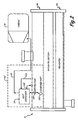
- FIG. 2 is a schematic of the evaporator and the turbine from FIG. 1 , as well as an oil recovery system for removing oil from the evaporator.
- FIG. 3 is another schematic of the evaporator, the turbine, and the oil recovery system, as well as an eductor system for removing oil from the turbine and delivering it back to an oil sump.
- An organic rankine cycle (ORC) system may be used to generate electrical power.
- Oil is used within the ORC system to provide lubrication for various pieces of equipment, particularly inside a turbine of the ORC system.
- the oil may travel to other parts of the ORC system. Commonly the oil travels with the refrigerant from the condenser to the evaporator. If the oil is not recovered from the evaporator, there may not be enough oil in the oil sump to startup the turbine or continue operating the turbine. In that case, a technician may be required to physically add oil to the oil sump to enable a startup of the system. The excess oil is then manually removed from the ORC system once the turbine is in an operational mode.
- This disclosure focuses on a method and system for recovering the oil from the evaporator so that the oil sump has an adequate amount of oil, especially for startup.
- FIG. 1 is a schematic of ORC system 10, which includes condenser 12, pump 14, evaporator 16, turbine 18, and eductor system 20 connected to turbine 18.
- Refrigerant 22 circulates through system 10 and is used to generate electrical power.
- Liquid refrigerant 22a from condenser 12 passes through pump 14, resulting in an increase in pressure.
- High pressure liquid refrigerant 22a enters evaporator 16, which utilizes heat source 24 to vaporize refrigerant 22.
- Heat source 24 may include, but is not limited to, any type of waste heat, including fuel cells, microturbines, and reciprocating engines, and other types of heat sources such as solar, geothermal or waste gas:
- Refrigerant 22 exiting evaporator 16 is a vaporized refrigerant (22b), at which point it passes through turbine inlet valve 26 and into turbine 18.
- Vaporized refrigerant 22b is used to drive turbine 18, which in turn powers generator 28 such that generator 28 produces electrical power.
- Vaporized refrigerant 22b exiting turbine 18 is returned to condenser 12, where it is condensed back to liquid refrigerant 22a.
- Heat sink 30 is used to provide cooling water to condenser 12.
- Eductor system 20 is connected to turbine 18 and is configured to remove oil from those areas of turbine 18 where it may commonly collect.
- eductor line 32 receives a portion of vaporized refrigerant 22b flowing from evaporator 16 and delivers refrigerant 22b to eductor system 20.
- oil is used primarily inside turbine 18. More specifically, the oil is commonly used for the gears and bearings of turbine 18 (see FIG. 3 ). During operation of system 10, however, some of the oil may leave turbine 18. In that case, the oil is typically carried by vaporized refrigerant 22b to condenser 12. The oil then combines with condensed refrigerant 22a exiting condenser 12 and travels with refrigerant 22a to evaporator 16. Depending on a design of evaporator 16, however, vaporized refrigerant 22b exiting evaporator 16 may not have enough velocity to transport the oil back to turbine 18. At some point, an oil level in an oil sump of turbine 18 may become too low.
- Heat exchanger 34 is connected to evaporator 16 and is configured to receive a mixture of oil (liquid) and refrigerant (liquid and vapor) from evaporator 16, and vaporize the liquid refrigerant. The mixture of oil and vaporized refrigerant then travels to turbine 18, at which point the oil and refrigerant are easily separated. The oil is then deliverable to the oil sump in turbine 18. This is described in more detail below in reference to FIGS. 2 and 3 .
- ORC system 10 also includes bypass valve 36 and bypass line 38, which may be used to prevent refrigerant 22b from passing through turbine 18 during a startup.
- turbine 18 temporarily runs in a bypass mode, at which time it does not receive any refrigerant, in order to reach the predetermined operating conditions (i.e. temperature and pressure) for turbine 18.
- refrigerant 22b flows through bypass line 38 and is directed through bypass orifice 39 to increase a temperature of refrigerant 22b, and imitate operating conditions inside turbine 18.
- bypass valve 36 is closed when turbine inlet valve 26 is open, and vice versa.
- FIG. 2 is a schematic of a portion of ORC system 10 from FIG. 1 , including evaporator 16, turbine 18, and heat exchanger 34, which is part of oil recovery system 100.
- evaporator 16 receives liquid refrigerant 22a and uses heat source 24 to vaporize refrigerant 22.
- evaporator 16 is a flooded evaporator, and includes a pre-heater section in bottom portion 16a and a saturated section in top portion 16b. Both the pre-heater section and the saturated section of evaporator 16 include a plurality of tubes, which are oriented horizontally inside evaporator 16.
- Refrigerant 22 flows over the tubes and is vaporized so that essentially all of refrigerant 22b traveling to turbine 18 is vaporized refrigerant.
- the liquid level of refrigerant inside evaporator 16 is maintained in order to keep the tubes wet during operation.
- Oil recovery system 100 includes heat exchanger 34, scavenger port 102, restriction orifice 104, refrigerant inlet line 106, refrigerant outlet line 108, and delivery line 110.
- Scavenger port 102 and restriction orifice 104 form a recovery line to remove a mixture of oil and refrigerant from evaporator 16 and deliver it to heat exchanger 34.
- Scavenger port 102 is located on a side of evaporator 16 above a top of the tubes in top portion 16b. In a preferred embodiment, port 102 is located approximately one inch (2.5 cm) above the top of the tubes.
- the level of liquid refrigerant in evaporator 16 which surrounds the tubes is normally maintained at a level near the location of scavenger port 102.
- the refrigerant in evaporator 16 is "pool boiling" over the tubes in the saturated section of evaporator 16. The resulting bubbles rise to the surface and a foam of refrigerant and oil forms. Oil inside evaporator 16 is concentrated at or near this surface.
- the oil/refrigerant mixture is removed from evaporator 16 through scavenger port 102.
- the oil in the mixture is a liquid and the refrigerant is commonly in both a liquid and a vapor phase.
- the oil/refrigerant mixture then flows through restriction orifice 104 in order to restrict a flow of the fluid entering heat exchanger 34.
- restriction orifice 104 may be substituted with an adjustable valve to control or restrict flow of the mixture to heat exchanger 34.
- Heat exchanger 34 receives the oil/refrigerant mixture and uses saturated vapor refrigerant, also from evaporator 16, to heat the mixture.
- heat exchanger 34 is a counter flow, flat plate heat exchanger.
- the saturated vapor refrigerant is removed from an uppermost part of evaporator 16, and is delivered to heat exchanger 34 through refrigerant inlet line 106. After passing through heat exchanger 34, the refrigerant is returned to evaporator 16 via refrigerant outlet line 108. Only a small percentage of saturated vapor refrigerant inside evaporator 16 is used by heat exchanger 34, and the refrigerant is recycled back to evaporator 16. Thus, using vaporized refrigerant to provide heating in heat exchanger 34 has little or no effect on operation and efficiency of evaporator 16.
- the oil/refrigerant mixture is now comprised of an oil-rich liquid and vaporized refrigerant. As such, the oil is now easily separable from the refrigerant.
- the oil/refrigerant mixture exits heat exchanger 34 and is delivered to turbine 18 via delivery line 110.
- scavenger port 102 is fixed to the side of evaporator 16.
- the location of port 102, as described above, is determined based on an operating level of liquid refrigerant inside evaporator 16.
- an oil skimmer which floats inside evaporator 16 may be used to remove oil (and refrigerant) from the surface of the liquid refrigerant.
- the oil skimmer moves with the refrigerant level inside evaporator 16.
- a tube connected to the oil skimmer may be used to deliver the oil and refrigerant mixture from the oil skimmer to a port on a top or side of evaporator 16. The oil/refrigerant mixture is then delivered from evaporator 16 to restriction orifice 104.
- FIG. 3 is a schematic of evaporator 16, turbine 18, and oil recovery system 100, all of FIG. 2 , as well as eductor system 20 for removing oil from turbine 18 and delivering it to oil sump 56.
- Turbine 18 includes impeller 40, discharge housing 42, and high pressure volute 44.
- Volute 44 is designated as "high pressure volute” since the volute is at high pressure when turbine 18 is operating. However, volute 44 is at low pressure when system 10 and turbine 18 are in the bypass mode during startup.
- vaporized refrigerant 22b passes through inlet valve 26 into high pressure volute 44, and then through nozzles 46, which impart motive force to impeller 40 to drive shaft 48 inside gear box 50.
- Gears 52 connect drive shaft 48 to generator 28, which uses the shaft energy to generate electrical power.
- Gear box 50 also includes bearings 54, oil sump 56, and oil pump 58.
- Eductor system 20 is used to remove oil from these areas of turbine 18 where oil is not needed, and in some cases may cause damage to the equipment.
- Eductor system 20 is configured to remove oil and return it to oil sump 56, making the oil available for other areas of turbine 18, such as, for example, gears 52 and bearings 54.
- Eductor line 32 is connected to eductor system 20 and is located upstream of turbine inlet valve 26. Line 32 is configured to receive a portion of vaporized refrigerant 22b exiting evaporator 16 (and flowing to turbine 18) and deliver it to eductor system 20.
- Delivery line 110 delivers the mixture of oil (liquid) and refrigerant (vapor) from heat exchanger 34 to discharge housing 42 of turbine 18.
- Discharge housing 42 acts as a separator such that the liquid oil collects in a bottom of discharge housing 42 and the vaporized refrigerant exits turbine 18 through a vent, and then travels to condenser 12.
- the oil from evaporator 16 is combined with any oil 76 already inside discharge housing 42, all of which may be removed from discharge housing 42 using eductor system 20.
- eductor system 20 includes first eductor 62 and second eductor 64, which operate as venturi devices, and each includes a primary flow inlet and a secondary flow inlet.
- first eductor 62 and second eductor 64 which operate as venturi devices, and each includes a primary flow inlet and a secondary flow inlet.
- high pressure refrigerant from evaporator 16 flows through the primary flow inlet, creating enough suction force to draw liquid out of turbine 18.
- Eductor system 20 also includes first line 66 and second line 68, both of which are connected to eductor line 32.
- First line 66 is configured to deliver refrigerant 22 to primary flow inlet 70 of first eductor 62.
- Secondary flow inlet 72 of first eductor 62 is connected to line 74 and delivers oil 76 from discharge housing 42 of turbine 18 through first eductor 62.
- Oil 76 thus includes oil from evaporator 16 delivered through line 110. (It is recognized that although the liquid sucked out of discharge housing 42 is primarily oil, the liquid may contain some amount of refrigerant.)
- Second line 68 is configured to deliver refrigerant 22 to primary flow inlet 78 of second eductor 64.
- Line 80 is connected to secondary flow inlet 82 of second eductor 64 and delivers liquid removed from high pressure volute 44 of turbine 18. Liquid extracted from high pressure volute 44 is mostly oil; however, the liquid may include some of the refrigerant flowing inside turbine 18. After flowing through eductors 62 and 64, the refrigerant and the oil collectively travel to oil sump 56 through line 84. The refrigerant, which is vapor, may be recycled back to discharge housing 42 from sump 56 via line 86.
- eductor system 20 may operate with only first eductor 62. Oil may collect in both discharge housing 42 and high pressure volute 44. Second eductor 64 is able to remove oil from high pressure volute 44, where it commonly collects once the oil is separated from the vaporized refrigerant inside volute 44. Using a two-eductor system improves overall recovery of the oil because the oil may be removed from both areas around impeller 40 where it can accumulate.
- ORC system 10 uses a two-eductor system in combination with oil recovery system 100.
- discharge housing 42 of turbine 18 functions as a separator to separate the liquid oil and the vaporized refrigerant from heat exchanger 34.
- ORC system 10 may be started up even when there is essentially no oil in oil sump 56.
- Oil recovery system 100 is able to effectively recover oil from evaporator 16 and deliver the oil to turbine 18, while system 10 is still in bypass mode, at which point eductor system 20 is used to deliver the oil back to oil sump 56. This may decrease or eliminate failed startups caused by not being able to supply oil to the gears and bearings inside the turbine.
- oil sump was low, oil was manually added to the oil sump before startup. This added costs to operation of the ORC system and usually required that the added oil be removed from the ORC system, once the turbine was in an operational mode.
- ORC system 10 alleviates a need to manually add oil to sump 56 by providing a method of effectively recovering the oil from evaporator 16 and delivering it to sump 56.
Landscapes
- Engineering & Computer Science (AREA)
- Mechanical Engineering (AREA)
- General Engineering & Computer Science (AREA)
- Chemical & Material Sciences (AREA)
- Combustion & Propulsion (AREA)
- Engine Equipment That Uses Special Cycles (AREA)
Abstract
Description
- The present disclosure relates to an organic rankine cycle (ORC) system. More particularly, the present disclosure relates to an improved method and system for recovering oil from an evaporator of an ORC system. An exemplary ORC system is disclosed in
JP 59-115407 - Rankine cycle systems are commonly used for generating electrical power. The rankine cycle system includes an evaporator or a boiler for evaporation of a motive fluid, a turbine that receives the vapor from the evaporator to drive a generator, a condenser for condensing the vapor, and a pump or other means for recycling the condensed fluid to the evaporator. The motive fluid in rankine cycle systems is often water, and the turbine is thus driven by steam. An organic rankine cycle (ORC) system operates similarly to a traditional rankine cycle, except that an ORC system uses an organic fluid, instead of water, as the motive fluid.
- Oil may be used for lubrication in the ORC system, particularly inside the turbine. For example, oil provides lubrication for the bearings of the turbine. During operation of the ORC system, the oil may migrate from the turbine to other areas of the system. The oil may travel, with the refrigerant, from the turbine to the condenser and then to the evaporator. In some cases, it may be difficult to recover the oil from the evaporator, which results in a decrease in an amount of oil available for operation of the turbine.
- There is a need for a method and system for recovering the oil from the evaporator of the ORC system and delivering it back to the turbine.
- Viewed from a first aspect, the present invention provides a system for recovering oil in an organic rankine cycle (ORC) system having an evaporator, a turbine, and a condenser, the system comprising: a recovery line configured to remove a mixture of oil and refrigerant from the evaporator; a heat exchanger configured to increase a temperature of the mixture such that liquid refrigerant in the mixture is vaporized to produce a mixture of oil and vaporized refrigerant; and a delivery line configured to deliver the mixture of oil and vaporized refrigerant to the turbine, characterised in that the delivery line delivers the mixture of oil and vaporized refrigerant to a discharge housing of the turbine, and the discharge housing separates the oil and the vaporized refrigerant.
Viewed from a second aspect, the present invention provides a method of recovering oil in an organic rankine cycle (ORC) system having an evaporator, a turbine, an oil sump, and a condenser, the method comprising: removing a mixture of oil and refrigerant from the evaporator; increasing a temperature of the mixture such that liquid refrigerant in the mixture vaporizes; separating the oil and the vaporized refrigerant; and delivering the oil to the oil sump, characterised in that separating the oil and the vaporized refrigerant is performed by a discharge housing of the turbine. -
FIG. 1 is a schematic of an organic rankine cycle (ORC) system, including an evaporator and a turbine. -
FIG. 2 is a schematic of the evaporator and the turbine fromFIG. 1 , as well as an oil recovery system for removing oil from the evaporator. -
FIG. 3 is another schematic of the evaporator, the turbine, and the oil recovery system, as well as an eductor system for removing oil from the turbine and delivering it back to an oil sump. - An organic rankine cycle (ORC) system may be used to generate electrical power. Oil is used within the ORC system to provide lubrication for various pieces of equipment, particularly inside a turbine of the ORC system. As the ORC is operating, however, the oil may travel to other parts of the ORC system. Commonly the oil travels with the refrigerant from the condenser to the evaporator. If the oil is not recovered from the evaporator, there may not be enough oil in the oil sump to startup the turbine or continue operating the turbine. In that case, a technician may be required to physically add oil to the oil sump to enable a startup of the system. The excess oil is then manually removed from the ORC system once the turbine is in an operational mode. This disclosure focuses on a method and system for recovering the oil from the evaporator so that the oil sump has an adequate amount of oil, especially for startup.
-
FIG. 1 is a schematic ofORC system 10, which includescondenser 12,pump 14,evaporator 16,turbine 18, andeductor system 20 connected toturbine 18. Refrigerant 22 circulates throughsystem 10 and is used to generate electrical power.Liquid refrigerant 22a fromcondenser 12 passes throughpump 14, resulting in an increase in pressure. High pressureliquid refrigerant 22a entersevaporator 16, which utilizesheat source 24 to vaporize refrigerant 22.Heat source 24 may include, but is not limited to, any type of waste heat, including fuel cells, microturbines, and reciprocating engines, and other types of heat sources such as solar, geothermal or waste gas: Refrigerant 22 exitingevaporator 16 is a vaporized refrigerant (22b), at which point it passes throughturbine inlet valve 26 and intoturbine 18. Vaporizedrefrigerant 22b is used to driveturbine 18, which inturn powers generator 28 such thatgenerator 28 produces electrical power. Vaporizedrefrigerant 22b exiting turbine 18 is returned tocondenser 12, where it is condensed back toliquid refrigerant 22a.Heat sink 30 is used to provide cooling water to condenser 12. -
Eductor system 20 is connected toturbine 18 and is configured to remove oil from those areas ofturbine 18 where it may commonly collect. As explained in more detail below in reference toFIG. 3 ,eductor line 32 receives a portion of vaporizedrefrigerant 22b flowing fromevaporator 16 and deliversrefrigerant 22b toeductor system 20. - Within
system 10, oil is used primarily insideturbine 18. More specifically, the oil is commonly used for the gears and bearings of turbine 18 (seeFIG. 3 ). During operation ofsystem 10, however, some of the oil may leaveturbine 18. In that case, the oil is typically carried by vaporizedrefrigerant 22b to condenser 12. The oil then combines with condensedrefrigerant 22a exiting condenser 12 and travels withrefrigerant 22a toevaporator 16. Depending on a design ofevaporator 16, however, vaporizedrefrigerant 22b exiting evaporator 16 may not have enough velocity to transport the oil back toturbine 18. At some point, an oil level in an oil sump ofturbine 18 may become too low.Heat exchanger 34 is connected toevaporator 16 and is configured to receive a mixture of oil (liquid) and refrigerant (liquid and vapor) fromevaporator 16, and vaporize the liquid refrigerant. The mixture of oil and vaporized refrigerant then travels toturbine 18, at which point the oil and refrigerant are easily separated. The oil is then deliverable to the oil sump inturbine 18. This is described in more detail below in reference toFIGS. 2 and3 . - As shown in
FIG. 1 ,ORC system 10 also includesbypass valve 36 andbypass line 38, which may be used to preventrefrigerant 22b from passing throughturbine 18 during a startup. During a startup ofsystem 10,turbine 18 temporarily runs in a bypass mode, at which time it does not receive any refrigerant, in order to reach the predetermined operating conditions (i.e. temperature and pressure) forturbine 18. In that case,refrigerant 22b flows throughbypass line 38 and is directed throughbypass orifice 39 to increase a temperature ofrefrigerant 22b, and imitate operating conditions insideturbine 18. After passing throughbypass orifice 39,refrigerant 22b is directed to condenser 12. In some embodiments,bypass valve 36 is closed whenturbine inlet valve 26 is open, and vice versa. -
FIG. 2 is a schematic of a portion ofORC system 10 fromFIG. 1 , includingevaporator 16,turbine 18, andheat exchanger 34, which is part ofoil recovery system 100. As described above in reference toFIG. 1 ,evaporator 16 receivesliquid refrigerant 22a and usesheat source 24 to vaporize refrigerant 22. In the exemplary embodiment shown inFIG. 2 ,evaporator 16 is a flooded evaporator, and includes a pre-heater section inbottom portion 16a and a saturated section intop portion 16b. Both the pre-heater section and the saturated section ofevaporator 16 include a plurality of tubes, which are oriented horizontally insideevaporator 16. Refrigerant 22 flows over the tubes and is vaporized so that essentially all ofrefrigerant 22b traveling toturbine 18 is vaporized refrigerant. The liquid level of refrigerant insideevaporator 16 is maintained in order to keep the tubes wet during operation. -
Oil recovery system 100 includesheat exchanger 34,scavenger port 102,restriction orifice 104,refrigerant inlet line 106,refrigerant outlet line 108, anddelivery line 110. Scavengerport 102 andrestriction orifice 104 form a recovery line to remove a mixture of oil and refrigerant fromevaporator 16 and deliver it toheat exchanger 34. Scavengerport 102 is located on a side ofevaporator 16 above a top of the tubes intop portion 16b. In a preferred embodiment,port 102 is located approximately one inch (2.5 cm) above the top of the tubes. During operation ofevaporator 16, the level of liquid refrigerant inevaporator 16 which surrounds the tubes is normally maintained at a level near the location ofscavenger port 102. The refrigerant inevaporator 16 is "pool boiling" over the tubes in the saturated section ofevaporator 16. The resulting bubbles rise to the surface and a foam of refrigerant and oil forms. Oil insideevaporator 16 is concentrated at or near this surface. - The oil/refrigerant mixture is removed from
evaporator 16 throughscavenger port 102. The oil in the mixture is a liquid and the refrigerant is commonly in both a liquid and a vapor phase. The oil/refrigerant mixture then flows throughrestriction orifice 104 in order to restrict a flow of the fluid enteringheat exchanger 34. The temperature and the pressure of the oil/refrigerant mixture decreases as it passes throughorifice 104. Alternatively,orifice 104 may be substituted with an adjustable valve to control or restrict flow of the mixture toheat exchanger 34. -
Heat exchanger 34 receives the oil/refrigerant mixture and uses saturated vapor refrigerant, also fromevaporator 16, to heat the mixture. In an exemplary embodiment,heat exchanger 34 is a counter flow, flat plate heat exchanger. The saturated vapor refrigerant is removed from an uppermost part ofevaporator 16, and is delivered toheat exchanger 34 throughrefrigerant inlet line 106. After passing throughheat exchanger 34, the refrigerant is returned toevaporator 16 viarefrigerant outlet line 108. Only a small percentage of saturated vapor refrigerant insideevaporator 16 is used byheat exchanger 34, and the refrigerant is recycled back toevaporator 16. Thus, using vaporized refrigerant to provide heating inheat exchanger 34 has little or no effect on operation and efficiency ofevaporator 16. - Due to heat transfer from the saturated vapor refrigerant, the oil/refrigerant mixture is now comprised of an oil-rich liquid and vaporized refrigerant. As such, the oil is now easily separable from the refrigerant. The oil/refrigerant mixture exits
heat exchanger 34 and is delivered toturbine 18 viadelivery line 110. - As shown in
FIG. 2 ,scavenger port 102 is fixed to the side ofevaporator 16. The location ofport 102, as described above, is determined based on an operating level of liquid refrigerant insideevaporator 16. In an alternative embodiment, instead ofscavenger port 102, an oil skimmer, which floats insideevaporator 16, may be used to remove oil (and refrigerant) from the surface of the liquid refrigerant. Thus, the oil skimmer moves with the refrigerant level insideevaporator 16. A tube connected to the oil skimmer may be used to deliver the oil and refrigerant mixture from the oil skimmer to a port on a top or side ofevaporator 16. The oil/refrigerant mixture is then delivered fromevaporator 16 torestriction orifice 104. -
FIG. 3 is a schematic ofevaporator 16,turbine 18, andoil recovery system 100, all ofFIG. 2 , as well aseductor system 20 for removing oil fromturbine 18 and delivering it tooil sump 56.Turbine 18 includesimpeller 40, dischargehousing 42, andhigh pressure volute 44. (Volute 44 is designated as "high pressure volute" since the volute is at high pressure whenturbine 18 is operating. However,volute 44 is at low pressure whensystem 10 andturbine 18 are in the bypass mode during startup.) During an operational mode ofturbine 18, vaporizedrefrigerant 22b (from evaporator 16) passes throughinlet valve 26 intohigh pressure volute 44, and then throughnozzles 46, which impart motive force toimpeller 40 to driveshaft 48 insidegear box 50.Gears 52 connectdrive shaft 48 togenerator 28, which uses the shaft energy to generate electrical power.Gear box 50 also includesbearings 54,oil sump 56, andoil pump 58. - During operation of
turbine 18, oil may commonly collect indischarge housing 42 andhigh pressure volute 44 ofturbine 18.Eductor system 20 is used to remove oil from these areas ofturbine 18 where oil is not needed, and in some cases may cause damage to the equipment.Eductor system 20 is configured to remove oil and return it tooil sump 56, making the oil available for other areas ofturbine 18, such as, for example, gears 52 andbearings 54.Eductor line 32 is connected toeductor system 20 and is located upstream ofturbine inlet valve 26.Line 32 is configured to receive a portion of vaporized refrigerant 22b exiting evaporator 16 (and flowing to turbine 18) and deliver it toeductor system 20. -
Delivery line 110 delivers the mixture of oil (liquid) and refrigerant (vapor) fromheat exchanger 34 to dischargehousing 42 ofturbine 18.Discharge housing 42 acts as a separator such that the liquid oil collects in a bottom ofdischarge housing 42 and the vaporized refrigerant exitsturbine 18 through a vent, and then travels to condenser 12. The oil fromevaporator 16 is combined with anyoil 76 already insidedischarge housing 42, all of which may be removed fromdischarge housing 42 usingeductor system 20. - In the embodiment shown in
FIG. 3 ,eductor system 20 includesfirst eductor 62 andsecond eductor 64, which operate as venturi devices, and each includes a primary flow inlet and a secondary flow inlet. In each eductor, high pressure refrigerant fromevaporator 16 flows through the primary flow inlet, creating enough suction force to draw liquid out ofturbine 18. -
Eductor system 20 also includesfirst line 66 andsecond line 68, both of which are connected toeductor line 32.First line 66 is configured to deliver refrigerant 22 toprimary flow inlet 70 offirst eductor 62.Secondary flow inlet 72 offirst eductor 62 is connected to line 74 and deliversoil 76 fromdischarge housing 42 ofturbine 18 throughfirst eductor 62.Oil 76 thus includes oil fromevaporator 16 delivered throughline 110. (It is recognized that although the liquid sucked out ofdischarge housing 42 is primarily oil, the liquid may contain some amount of refrigerant.)Second line 68 is configured to deliver refrigerant 22 toprimary flow inlet 78 ofsecond eductor 64.Line 80 is connected tosecondary flow inlet 82 ofsecond eductor 64 and delivers liquid removed fromhigh pressure volute 44 ofturbine 18. Liquid extracted fromhigh pressure volute 44 is mostly oil; however, the liquid may include some of the refrigerant flowing insideturbine 18. After flowing througheductors oil sump 56 throughline 84. The refrigerant, which is vapor, may be recycled back to dischargehousing 42 fromsump 56 vialine 86. - Although
eductor system 20, as shown inFIG. 3 , includes two eductors, it is recognized thateductor system 20 may operate with onlyfirst eductor 62. Oil may collect in both dischargehousing 42 andhigh pressure volute 44.Second eductor 64 is able to remove oil fromhigh pressure volute 44, where it commonly collects once the oil is separated from the vaporized refrigerant insidevolute 44. Using a two-eductor system improves overall recovery of the oil because the oil may be removed from both areas aroundimpeller 40 where it can accumulate. - In terms of recovering oil from
evaporator 16, onlyfirst eductor 62 is required to effectively recover the oil tosump 56.Second eductor 64 is used to remove oil fromhigh pressure volute 44 and, generally speaking, does not impact recovery of oil fromevaporator 16. As explained above, however,second eductor 64 improves an overall recovery of oil that collects aroundimpeller 40 ofturbine 18. Thus, in one preferred embodiment,ORC system 10 uses a two-eductor system in combination withoil recovery system 100. - As stated above, discharge
housing 42 ofturbine 18 functions as a separator to separate the liquid oil and the vaporized refrigerant fromheat exchanger 34. - Using
oil recovery system 100 andeductor system 20,ORC system 10 may be started up even when there is essentially no oil inoil sump 56.Oil recovery system 100 is able to effectively recover oil fromevaporator 16 and deliver the oil toturbine 18, whilesystem 10 is still in bypass mode, at whichpoint eductor system 20 is used to deliver the oil back tooil sump 56. This may decrease or eliminate failed startups caused by not being able to supply oil to the gears and bearings inside the turbine. In some cases, if the oil sump was low, oil was manually added to the oil sump before startup. This added costs to operation of the ORC system and usually required that the added oil be removed from the ORC system, once the turbine was in an operational mode.ORC system 10 alleviates a need to manually add oil tosump 56 by providing a method of effectively recovering the oil fromevaporator 16 and delivering it tosump 56. - Although the present invention has been described with reference to preferred embodiments, workers skilled in the art will recognize that changes may be made in form and detail without departing from the scope of the invention, which is defined by the claims.
Claims (11)
- A system (100) for recovering oil in an organic rankine cycle (ORC) system having an evaporator (16), a turbine (18), and a condenser (12), the system comprising:a recovery line (102, 104) configured to remove a mixture of oil and refrigerant from the evaporator;a heat exchanger (34) configured to increase a temperature of the mixture such that liquid refrigerant in the mixture is vaporized to produce a mixture of oil and vaporized refrigerant; anda delivery line (110) configured to deliver the mixture of oil and vaporized refrigerant to the turbine,characterised in that the delivery line (110) is suitable for delivering the mixture of oil and vaporized refrigerant to a discharge housing (42) of the turbine, and the discharge housing is suitable for separating the oil and the vaporized refrigerant.
- The system of claim 1 wherein the recovery line includes a scavenger port (102) to remove the mixture of oil and refrigerant from the evaporator.
- The system of claim 1 wherein the recovery line includes an oil skimmer configured to float on a liquid refrigerant inside the evaporator, and remove the oil and refrigerant mixture from the evaporator.
- The system of claim 1, 2 or 3, wherein the recovery line includes an orifice (104) to restrict a flow of the mixture, prior to passing the liquid mixture through the heat exchanger.
- The system of any preceding claim further comprising:a first eductor (62) for extracting liquid out of the turbine and delivering the liquid to an oil sump (56).
- A method of recovering oil in an organic rankine cycle (ORC) system having an evaporator (16), a turbine (18), an oil sump (56), and a condenser (12), the method comprising:removing a mixture of oil and refrigerant from the evaporator;increasing a temperature of the mixture such that liquid refrigerant in the mixture vaporizes;separating the oil and the vaporized refrigerant; anddelivering the oil to the oil sump,characterised in that separating the oil and the vaporized refrigerant is performed by a discharge housing (42) of the turbine.
- The method of claim 6 further comprising:delivering the vaporized refrigerant to the condenser (12), after separating the oil and the vaporized refrigerant.
- The method of claim 6 or 7 wherein delivering the oil to the oil sump comprises:delivering the oil to a discharge housing (42) of the turbine;removing the oil from the discharge housing using an eductor system (62).
- The method of claim 6, 7 or 8 further comprising:restricting a flow of the mixture of oil and refrigerant using an orifice (104), prior to increasing a temperature of the mixture.
- The method of any of claims 6 to 9 wherein removing the mixture of oil and refrigerant from the evaporator is performed by a scavenger port (102) connected to the evaporator.
- The method of any of claims 6 to 9 wherein removing the mixture of oil and refrigerant from the evaporator is performed by an oil skimmer inside the evaporator.
Applications Claiming Priority (1)
| Application Number | Priority Date | Filing Date | Title |
|---|---|---|---|
| PCT/US2007/016943 WO2009017473A2 (en) | 2007-07-27 | 2007-07-27 | Oil recovery from an evaporator of an organic rankine cycle (orc) system |
Publications (2)
| Publication Number | Publication Date |
|---|---|
| EP2222939A2 EP2222939A2 (en) | 2010-09-01 |
| EP2222939B1 true EP2222939B1 (en) | 2013-11-20 |
Family
ID=40305082
Family Applications (1)
| Application Number | Title | Priority Date | Filing Date |
|---|---|---|---|
| EP07797042.4A Active EP2222939B1 (en) | 2007-07-27 | 2007-07-27 | Oil recovery from an evaporator of an organic rankine cycle (orc) system |
Country Status (9)
| Country | Link |
|---|---|
| US (1) | US8769952B2 (en) |
| EP (1) | EP2222939B1 (en) |
| JP (1) | JP5174905B2 (en) |
| CN (1) | CN101970808B (en) |
| AU (1) | AU2007357134B2 (en) |
| CA (1) | CA2694682C (en) |
| ES (1) | ES2440488T3 (en) |
| MX (1) | MX344051B (en) |
| WO (1) | WO2009017473A2 (en) |
Cited By (1)
| Publication number | Priority date | Publication date | Assignee | Title |
|---|---|---|---|---|
| US11592009B2 (en) | 2021-04-02 | 2023-02-28 | Ice Thermal Harvesting, Llc | Systems and methods for generation of electrical power at a drilling rig |
Families Citing this family (37)
| Publication number | Priority date | Publication date | Assignee | Title |
|---|---|---|---|---|
| WO2009136919A1 (en) * | 2008-05-07 | 2009-11-12 | Utc Power Corporation | Passive oil level limiter |
| US20100060005A1 (en) * | 2008-09-05 | 2010-03-11 | Bhatti Mohinder S | Power generation system using low grade solar energy |
| US8627663B2 (en) | 2009-09-02 | 2014-01-14 | Cummins Intellectual Properties, Inc. | Energy recovery system and method using an organic rankine cycle with condenser pressure regulation |
| DE102010022408B4 (en) | 2010-06-01 | 2016-11-24 | Man Truck & Bus Ag | Method and apparatus for operating a steam cycle with lubricated expander |
| US8813498B2 (en) * | 2010-06-18 | 2014-08-26 | General Electric Company | Turbine inlet condition controlled organic rankine cycle |
| EP2603673B1 (en) * | 2010-08-13 | 2019-12-25 | Cummins Intellectual Properties, Inc. | Rankine cycle condenser pressure control using an energy conversion device bypass valve |
| DE102010056297B3 (en) | 2010-12-24 | 2011-12-15 | Robert Bosch Gmbh | Waste heat utilization system |
| JP5743719B2 (en) | 2011-05-31 | 2015-07-01 | 出光興産株式会社 | Grease for bearing |
| DE102011053310B4 (en) * | 2011-09-06 | 2016-07-28 | Technische Universität Berlin | Method for operating a refrigeration system and refrigeration system |
| US9903232B2 (en) * | 2011-12-22 | 2018-02-27 | Ormat Technologies Inc. | Power and regasification system for LNG |
| US9032753B2 (en) * | 2012-03-22 | 2015-05-19 | Trane International Inc. | Electronics cooling using lubricant return for a shell-and-tube style evaporator |
| US9032754B2 (en) * | 2012-03-22 | 2015-05-19 | Trane International Inc. | Electronics cooling using lubricant return for a shell-and-tube evaporator |
| GB2526741A (en) | 2013-03-15 | 2015-12-02 | Trane Int Inc | Apparatuses, systems, and methods of variable frequency drive operation and control |
| WO2014158329A1 (en) * | 2013-03-25 | 2014-10-02 | Carrier Corporation | Compressor bearing cooling |
| US9664180B2 (en) * | 2014-02-28 | 2017-05-30 | John A. Saavedra | Power generating system utilizing expanding liquid |
| US11767824B2 (en) | 2014-02-28 | 2023-09-26 | Look For The Power Llc | Power generating system utilizing expanding fluid |
| KR20180069407A (en) * | 2016-12-15 | 2018-06-25 | 한국과학기술연구원 | Organic rankine cycle |
| CN111373213B (en) | 2017-09-25 | 2022-04-05 | 江森自控科技公司 | Two stage oil powered injector system |
| CN110552750B (en) * | 2019-08-23 | 2022-03-29 | 中国科学院广州能源研究所 | Non-azeotropic organic Rankine-dual-injection combined cooling, heating and power system |
| CN112065523A (en) * | 2020-07-31 | 2020-12-11 | 浙江柯茂节能环保工程设备有限公司 | Semi-closed screw type waste heat power generation system |
| US12312981B2 (en) | 2021-04-02 | 2025-05-27 | Ice Thermal Harvesting, Llc | Systems and methods utilizing gas temperature as a power source |
| US11326550B1 (en) | 2021-04-02 | 2022-05-10 | Ice Thermal Harvesting, Llc | Systems and methods utilizing gas temperature as a power source |
| US11293414B1 (en) | 2021-04-02 | 2022-04-05 | Ice Thermal Harvesting, Llc | Systems and methods for generation of electrical power in an organic rankine cycle operation |
| US11280322B1 (en) | 2021-04-02 | 2022-03-22 | Ice Thermal Harvesting, Llc | Systems for generating geothermal power in an organic Rankine cycle operation during hydrocarbon production based on wellhead fluid temperature |
| US11421663B1 (en) | 2021-04-02 | 2022-08-23 | Ice Thermal Harvesting, Llc | Systems and methods for generation of electrical power in an organic Rankine cycle operation |
| US11480074B1 (en) | 2021-04-02 | 2022-10-25 | Ice Thermal Harvesting, Llc | Systems and methods utilizing gas temperature as a power source |
| US11493029B2 (en) | 2021-04-02 | 2022-11-08 | Ice Thermal Harvesting, Llc | Systems and methods for generation of electrical power at a drilling rig |
| US11486370B2 (en) | 2021-04-02 | 2022-11-01 | Ice Thermal Harvesting, Llc | Modular mobile heat generation unit for generation of geothermal power in organic Rankine cycle operations |
| US11644015B2 (en) | 2021-04-02 | 2023-05-09 | Ice Thermal Harvesting, Llc | Systems and methods for generation of electrical power at a drilling rig |
| US11187185B1 (en) | 2021-04-05 | 2021-11-30 | Cummins Inc. | Waste heat recovery lube oil management |
| US11525399B1 (en) * | 2021-06-17 | 2022-12-13 | Pratt & Whitney Canada Corp. | Oil system with flow restrictor |
| JP7663435B2 (en) * | 2021-07-06 | 2025-04-16 | ヤンマーホールディングス株式会社 | Waste heat power generation system |
| WO2024054577A1 (en) * | 2022-09-08 | 2024-03-14 | Johnson Controls Tyco IP Holdings LLP | Lubricant separation system for hvac&r system |
| CN115596524A (en) * | 2022-12-01 | 2023-01-13 | 南京天加能源科技有限公司(Cn) | Organic Rankine cycle injection oil return device |
| US12534990B2 (en) | 2022-12-29 | 2026-01-27 | Ice Thermal Harvesting, Llc | Power generation assemblies for hydraulic fracturing systems and methods |
| US12180861B1 (en) | 2022-12-30 | 2024-12-31 | Ice Thermal Harvesting, Llc | Systems and methods to utilize heat carriers in conversion of thermal energy |
| IT202300006051A1 (en) * | 2023-03-29 | 2024-09-29 | Turboden Spa | DEVICE FOR CONTINUOUS OIL SEPARATION IN AN ORGANIC RANKINE CYCLE PLANT |
Family Cites Families (30)
| Publication number | Priority date | Publication date | Assignee | Title |
|---|---|---|---|---|
| GB816507A (en) | 1955-11-18 | 1959-07-15 | Air Prod Inc | Apparatus for extracting energy from an elastic fluid such as gas |
| JPS5460634A (en) | 1977-10-24 | 1979-05-16 | Agency Of Ind Science & Technol | Lubrication of turbine of rankine cycle engine |
| JPS5832908A (en) * | 1981-08-24 | 1983-02-26 | Hitachi Ltd | Rankine engine oil separator |
| JPS59115407A (en) | 1982-12-22 | 1984-07-03 | Hitachi Ltd | Cold heat power generating equipment |
| JPS6035105A (en) * | 1983-08-08 | 1985-02-22 | Hitachi Ltd | Lng based generating equipment by rankine cycle |
| JPH02219960A (en) | 1989-02-21 | 1990-09-03 | Sanki Eng Co Ltd | Direct contact type freezing system |
| US5182919A (en) * | 1990-01-18 | 1993-02-02 | Ebara Corporation | Oil recovery system for closed type centrifugal refrigerating machine |
| US6834514B2 (en) | 2002-07-08 | 2004-12-28 | Denso Corporation | Ejector cycle |
| US7281379B2 (en) | 2002-11-13 | 2007-10-16 | Utc Power Corporation | Dual-use radial turbomachine |
| US7254949B2 (en) | 2002-11-13 | 2007-08-14 | Utc Power Corporation | Turbine with vaned nozzles |
| US7174716B2 (en) | 2002-11-13 | 2007-02-13 | Utc Power Llc | Organic rankine cycle waste heat applications |
| US6880344B2 (en) | 2002-11-13 | 2005-04-19 | Utc Power, Llc | Combined rankine and vapor compression cycles |
| US7146813B2 (en) | 2002-11-13 | 2006-12-12 | Utc Power, Llc | Power generation with a centrifugal compressor |
| US6672102B1 (en) * | 2002-11-27 | 2004-01-06 | Carrier Corporation | Oil recovery and lubrication system for screw compressor refrigeration machine |
| JP2004346843A (en) * | 2003-05-22 | 2004-12-09 | Ebara Corp | Power generating device and power generating method |
| US20040237555A1 (en) * | 2003-05-30 | 2004-12-02 | Andrews Craig C. | Mechanical refrigeration system with a high turndown ratio |
| US6962051B2 (en) | 2003-06-17 | 2005-11-08 | Utc Power, Llc | Control of flow through a vapor generator |
| US6989989B2 (en) | 2003-06-17 | 2006-01-24 | Utc Power Llc | Power converter cooling |
| US6986251B2 (en) | 2003-06-17 | 2006-01-17 | Utc Power, Llc | Organic rankine cycle system for use with a reciprocating engine |
| US7013644B2 (en) | 2003-11-18 | 2006-03-21 | Utc Power, Llc | Organic rankine cycle system with shared heat exchanger for use with a reciprocating engine |
| US6996968B2 (en) * | 2003-12-17 | 2006-02-14 | United Technologies Corporation | Bifurcated oil scavenge system for a gas turbine engine |
| US7100380B2 (en) | 2004-02-03 | 2006-09-05 | United Technologies Corporation | Organic rankine cycle fluid |
| US7290393B2 (en) | 2004-05-06 | 2007-11-06 | Utc Power Corporation | Method for synchronizing an induction generator of an ORC plant to a grid |
| US7038329B1 (en) | 2004-11-04 | 2006-05-02 | Utc Power, Llc | Quality power from induction generator feeding variable speed motors |
| US7665304B2 (en) * | 2004-11-30 | 2010-02-23 | Carrier Corporation | Rankine cycle device having multiple turbo-generators |
| US7043912B1 (en) | 2004-12-27 | 2006-05-16 | Utc Power, Llc | Apparatus for extracting exhaust heat from waste heat sources while preventing backflow and corrosion |
| EP1869293B1 (en) | 2005-03-29 | 2013-05-08 | UTC Power Corporation | Cascaded organic rankine cycles for waste heat utilization |
| JP4659503B2 (en) * | 2005-03-31 | 2011-03-30 | 株式会社荏原製作所 | Power generation device and lubricating oil recovery method |
| CN101341650B (en) | 2005-12-19 | 2013-04-24 | 开利公司 | On-site power generation equipment control |
| US8561405B2 (en) * | 2007-06-29 | 2013-10-22 | General Electric Company | System and method for recovering waste heat |
-
2007
- 2007-07-27 CA CA2694682A patent/CA2694682C/en active Active
- 2007-07-27 US US12/670,764 patent/US8769952B2/en not_active Expired - Fee Related
- 2007-07-27 ES ES07797042.4T patent/ES2440488T3/en active Active
- 2007-07-27 CN CN200780100056.2A patent/CN101970808B/en active Active
- 2007-07-27 WO PCT/US2007/016943 patent/WO2009017473A2/en not_active Ceased
- 2007-07-27 EP EP07797042.4A patent/EP2222939B1/en active Active
- 2007-07-27 MX MX2010001078A patent/MX344051B/en active IP Right Grant
- 2007-07-27 AU AU2007357134A patent/AU2007357134B2/en not_active Ceased
- 2007-07-27 JP JP2010518154A patent/JP5174905B2/en not_active Expired - Fee Related
Cited By (1)
| Publication number | Priority date | Publication date | Assignee | Title |
|---|---|---|---|---|
| US11592009B2 (en) | 2021-04-02 | 2023-02-28 | Ice Thermal Harvesting, Llc | Systems and methods for generation of electrical power at a drilling rig |
Also Published As
| Publication number | Publication date |
|---|---|
| MX344051B (en) | 2016-12-02 |
| CN101970808A (en) | 2011-02-09 |
| WO2009017473A3 (en) | 2010-08-12 |
| AU2007357134B2 (en) | 2014-04-17 |
| WO2009017473A2 (en) | 2009-02-05 |
| ES2440488T3 (en) | 2014-01-29 |
| CN101970808B (en) | 2014-08-13 |
| EP2222939A2 (en) | 2010-09-01 |
| AU2007357134A1 (en) | 2009-02-05 |
| US20100186410A1 (en) | 2010-07-29 |
| US8769952B2 (en) | 2014-07-08 |
| JP2011503405A (en) | 2011-01-27 |
| MX2010001078A (en) | 2010-08-04 |
| CA2694682C (en) | 2014-12-02 |
| CA2694682A1 (en) | 2009-02-05 |
| JP5174905B2 (en) | 2013-04-03 |
Similar Documents
| Publication | Publication Date | Title |
|---|---|---|
| CA2694682C (en) | Oil recovery from an evaporator of an organic rankine cycle (orc) system | |
| EP2179145B1 (en) | Oil removal from a turbine of an organic rankine cycle (orc) system | |
| EP2185872B1 (en) | Method and apparatus for starting a refrigerant system without preheating the oil | |
| US9879885B2 (en) | Cooling water supply system and binary cycle power plant including same | |
| ITUB20155317A1 (en) | ORC binary cycle geothermal plant and process | |
| US8601814B2 (en) | Geothermal binary cycle power plant with geothermal steam condensate recovery system | |
| BR102014023072A2 (en) | vacuum condensing system using evaporative condenser and air removal system coupled to thermoelectric condensing turbines | |
| KR20140036972A (en) | System combining power generation apparatus and desalination apparatus | |
| WO2002023027A1 (en) | Water supply system for steam injection and inlet fogging in a gas turbine powerplant and operating method for this system | |
| JP2012057520A (en) | Cooling device for lubricating oil | |
| JPH0242102A (en) | Method for recovering thermal energy and apparatus thereof | |
| KR20160054652A (en) | Hybrid system of steam jet vacuum cooling unit | |
| JP2016098803A (en) | Geothermal power generation system | |
| EP3445954A1 (en) | Combined cycle power plant having condensate recirculation pump using venturi effect | |
| JP2016098805A (en) | Geothermal power generation system | |
| CN106062319A (en) | Flash tank design | |
| JP2006283674A (en) | Power generating device and lubricating oil recovery method | |
| EP0026676A2 (en) | Thermodynamic power plant and method of operating the same |
Legal Events
| Date | Code | Title | Description |
|---|---|---|---|
| PUAI | Public reference made under article 153(3) epc to a published international application that has entered the european phase |
Free format text: ORIGINAL CODE: 0009012 |
|
| 17P | Request for examination filed |
Effective date: 20100301 |
|
| AK | Designated contracting states |
Kind code of ref document: A2 Designated state(s): AT BE BG CH CY CZ DE DK EE ES FI FR GB GR HU IE IS IT LI LT LU LV MC MT NL PL PT RO SE SI SK TR |
|
| AX | Request for extension of the european patent |
Extension state: AL BA HR MK RS |
|
| R17D | Deferred search report published (corrected) |
Effective date: 20100812 |
|
| DAX | Request for extension of the european patent (deleted) | ||
| 17Q | First examination report despatched |
Effective date: 20121023 |
|
| GRAP | Despatch of communication of intention to grant a patent |
Free format text: ORIGINAL CODE: EPIDOSNIGR1 |
|
| INTG | Intention to grant announced |
Effective date: 20130603 |
|
| RIN1 | Information on inventor provided before grant (corrected) |
Inventor name: COGSWELL, FREDERICK J. Inventor name: MATTESON, PETER S. Inventor name: BIEDERMAN, BRUCE P. Inventor name: JONSSON, ULF J. Inventor name: ARNER, MICHAEL D. |
|
| GRAS | Grant fee paid |
Free format text: ORIGINAL CODE: EPIDOSNIGR3 |
|
| GRAA | (expected) grant |
Free format text: ORIGINAL CODE: 0009210 |
|
| AK | Designated contracting states |
Kind code of ref document: B1 Designated state(s): AT BE BG CH CY CZ DE DK EE ES FI FR GB GR HU IE IS IT LI LT LU LV MC MT NL PL PT RO SE SI SK TR |
|
| REG | Reference to a national code |
Ref country code: GB Ref legal event code: FG4D |
|
| REG | Reference to a national code |
Ref country code: CH Ref legal event code: EP |
|
| REG | Reference to a national code |
Ref country code: AT Ref legal event code: REF Ref document number: 641785 Country of ref document: AT Kind code of ref document: T Effective date: 20131215 |
|
| REG | Reference to a national code |
Ref country code: IE Ref legal event code: FG4D |
|
| REG | Reference to a national code |
Ref country code: DE Ref legal event code: R096 Ref document number: 602007033917 Country of ref document: DE Effective date: 20140116 |
|
| REG | Reference to a national code |
Ref country code: ES Ref legal event code: FG2A Ref document number: 2440488 Country of ref document: ES Kind code of ref document: T3 Effective date: 20140129 |
|
| REG | Reference to a national code |
Ref country code: NL Ref legal event code: VDEP Effective date: 20131120 |
|
| REG | Reference to a national code |
Ref country code: AT Ref legal event code: MK05 Ref document number: 641785 Country of ref document: AT Kind code of ref document: T Effective date: 20131120 |
|
| REG | Reference to a national code |
Ref country code: LT Ref legal event code: MG4D |
|
| PG25 | Lapsed in a contracting state [announced via postgrant information from national office to epo] |
Ref country code: FI Free format text: LAPSE BECAUSE OF FAILURE TO SUBMIT A TRANSLATION OF THE DESCRIPTION OR TO PAY THE FEE WITHIN THE PRESCRIBED TIME-LIMIT Effective date: 20131120 Ref country code: LT Free format text: LAPSE BECAUSE OF FAILURE TO SUBMIT A TRANSLATION OF THE DESCRIPTION OR TO PAY THE FEE WITHIN THE PRESCRIBED TIME-LIMIT Effective date: 20131120 Ref country code: SE Free format text: LAPSE BECAUSE OF FAILURE TO SUBMIT A TRANSLATION OF THE DESCRIPTION OR TO PAY THE FEE WITHIN THE PRESCRIBED TIME-LIMIT Effective date: 20131120 Ref country code: NL Free format text: LAPSE BECAUSE OF FAILURE TO SUBMIT A TRANSLATION OF THE DESCRIPTION OR TO PAY THE FEE WITHIN THE PRESCRIBED TIME-LIMIT Effective date: 20131120 Ref country code: IS Free format text: LAPSE BECAUSE OF FAILURE TO SUBMIT A TRANSLATION OF THE DESCRIPTION OR TO PAY THE FEE WITHIN THE PRESCRIBED TIME-LIMIT Effective date: 20140320 |
|
| PG25 | Lapsed in a contracting state [announced via postgrant information from national office to epo] |
Ref country code: AT Free format text: LAPSE BECAUSE OF FAILURE TO SUBMIT A TRANSLATION OF THE DESCRIPTION OR TO PAY THE FEE WITHIN THE PRESCRIBED TIME-LIMIT Effective date: 20131120 Ref country code: BE Free format text: LAPSE BECAUSE OF FAILURE TO SUBMIT A TRANSLATION OF THE DESCRIPTION OR TO PAY THE FEE WITHIN THE PRESCRIBED TIME-LIMIT Effective date: 20131120 Ref country code: LV Free format text: LAPSE BECAUSE OF FAILURE TO SUBMIT A TRANSLATION OF THE DESCRIPTION OR TO PAY THE FEE WITHIN THE PRESCRIBED TIME-LIMIT Effective date: 20131120 |
|
| PG25 | Lapsed in a contracting state [announced via postgrant information from national office to epo] |
Ref country code: PT Free format text: LAPSE BECAUSE OF FAILURE TO SUBMIT A TRANSLATION OF THE DESCRIPTION OR TO PAY THE FEE WITHIN THE PRESCRIBED TIME-LIMIT Effective date: 20140320 |
|
| PG25 | Lapsed in a contracting state [announced via postgrant information from national office to epo] |
Ref country code: EE Free format text: LAPSE BECAUSE OF FAILURE TO SUBMIT A TRANSLATION OF THE DESCRIPTION OR TO PAY THE FEE WITHIN THE PRESCRIBED TIME-LIMIT Effective date: 20131120 |
|
| REG | Reference to a national code |
Ref country code: DE Ref legal event code: R097 Ref document number: 602007033917 Country of ref document: DE |
|
| PG25 | Lapsed in a contracting state [announced via postgrant information from national office to epo] |
Ref country code: SK Free format text: LAPSE BECAUSE OF FAILURE TO SUBMIT A TRANSLATION OF THE DESCRIPTION OR TO PAY THE FEE WITHIN THE PRESCRIBED TIME-LIMIT Effective date: 20131120 Ref country code: CZ Free format text: LAPSE BECAUSE OF FAILURE TO SUBMIT A TRANSLATION OF THE DESCRIPTION OR TO PAY THE FEE WITHIN THE PRESCRIBED TIME-LIMIT Effective date: 20131120 Ref country code: PL Free format text: LAPSE BECAUSE OF FAILURE TO SUBMIT A TRANSLATION OF THE DESCRIPTION OR TO PAY THE FEE WITHIN THE PRESCRIBED TIME-LIMIT Effective date: 20131120 Ref country code: RO Free format text: LAPSE BECAUSE OF FAILURE TO SUBMIT A TRANSLATION OF THE DESCRIPTION OR TO PAY THE FEE WITHIN THE PRESCRIBED TIME-LIMIT Effective date: 20131120 |
|
| PLBE | No opposition filed within time limit |
Free format text: ORIGINAL CODE: 0009261 |
|
| STAA | Information on the status of an ep patent application or granted ep patent |
Free format text: STATUS: NO OPPOSITION FILED WITHIN TIME LIMIT |
|
| PG25 | Lapsed in a contracting state [announced via postgrant information from national office to epo] |
Ref country code: DK Free format text: LAPSE BECAUSE OF FAILURE TO SUBMIT A TRANSLATION OF THE DESCRIPTION OR TO PAY THE FEE WITHIN THE PRESCRIBED TIME-LIMIT Effective date: 20131120 |
|
| 26N | No opposition filed |
Effective date: 20140821 |
|
| REG | Reference to a national code |
Ref country code: DE Ref legal event code: R097 Ref document number: 602007033917 Country of ref document: DE Effective date: 20140821 |
|
| PG25 | Lapsed in a contracting state [announced via postgrant information from national office to epo] |
Ref country code: SI Free format text: LAPSE BECAUSE OF FAILURE TO SUBMIT A TRANSLATION OF THE DESCRIPTION OR TO PAY THE FEE WITHIN THE PRESCRIBED TIME-LIMIT Effective date: 20131120 Ref country code: LU Free format text: LAPSE BECAUSE OF FAILURE TO SUBMIT A TRANSLATION OF THE DESCRIPTION OR TO PAY THE FEE WITHIN THE PRESCRIBED TIME-LIMIT Effective date: 20140727 |
|
| REG | Reference to a national code |
Ref country code: CH Ref legal event code: PL |
|
| REG | Reference to a national code |
Ref country code: IE Ref legal event code: MM4A |
|
| PG25 | Lapsed in a contracting state [announced via postgrant information from national office to epo] |
Ref country code: LI Free format text: LAPSE BECAUSE OF NON-PAYMENT OF DUE FEES Effective date: 20140731 Ref country code: CH Free format text: LAPSE BECAUSE OF NON-PAYMENT OF DUE FEES Effective date: 20140731 |
|
| PG25 | Lapsed in a contracting state [announced via postgrant information from national office to epo] |
Ref country code: IE Free format text: LAPSE BECAUSE OF NON-PAYMENT OF DUE FEES Effective date: 20140727 |
|
| PG25 | Lapsed in a contracting state [announced via postgrant information from national office to epo] |
Ref country code: MC Free format text: LAPSE BECAUSE OF FAILURE TO SUBMIT A TRANSLATION OF THE DESCRIPTION OR TO PAY THE FEE WITHIN THE PRESCRIBED TIME-LIMIT Effective date: 20131120 |
|
| PG25 | Lapsed in a contracting state [announced via postgrant information from national office to epo] |
Ref country code: BG Free format text: LAPSE BECAUSE OF FAILURE TO SUBMIT A TRANSLATION OF THE DESCRIPTION OR TO PAY THE FEE WITHIN THE PRESCRIBED TIME-LIMIT Effective date: 20131120 |
|
| PG25 | Lapsed in a contracting state [announced via postgrant information from national office to epo] |
Ref country code: CY Free format text: LAPSE BECAUSE OF FAILURE TO SUBMIT A TRANSLATION OF THE DESCRIPTION OR TO PAY THE FEE WITHIN THE PRESCRIBED TIME-LIMIT Effective date: 20131120 Ref country code: GR Free format text: LAPSE BECAUSE OF FAILURE TO SUBMIT A TRANSLATION OF THE DESCRIPTION OR TO PAY THE FEE WITHIN THE PRESCRIBED TIME-LIMIT Effective date: 20140221 Ref country code: MT Free format text: LAPSE BECAUSE OF FAILURE TO SUBMIT A TRANSLATION OF THE DESCRIPTION OR TO PAY THE FEE WITHIN THE PRESCRIBED TIME-LIMIT Effective date: 20131120 |
|
| PG25 | Lapsed in a contracting state [announced via postgrant information from national office to epo] |
Ref country code: HU Free format text: LAPSE BECAUSE OF FAILURE TO SUBMIT A TRANSLATION OF THE DESCRIPTION OR TO PAY THE FEE WITHIN THE PRESCRIBED TIME-LIMIT; INVALID AB INITIO Effective date: 20070727 |
|
| REG | Reference to a national code |
Ref country code: FR Ref legal event code: PLFP Year of fee payment: 10 |
|
| REG | Reference to a national code |
Ref country code: FR Ref legal event code: PLFP Year of fee payment: 11 |
|
| REG | Reference to a national code |
Ref country code: DE Ref legal event code: R082 Ref document number: 602007033917 Country of ref document: DE Representative=s name: SCHMITT-NILSON SCHRAUD WAIBEL WOHLFROM PATENTA, DE |
|
| REG | Reference to a national code |
Ref country code: FR Ref legal event code: PLFP Year of fee payment: 12 |
|
| PGFP | Annual fee paid to national office [announced via postgrant information from national office to epo] |
Ref country code: IT Payment date: 20220613 Year of fee payment: 16 Ref country code: GB Payment date: 20220606 Year of fee payment: 16 |
|
| PGFP | Annual fee paid to national office [announced via postgrant information from national office to epo] |
Ref country code: FR Payment date: 20220609 Year of fee payment: 16 |
|
| PGFP | Annual fee paid to national office [announced via postgrant information from national office to epo] |
Ref country code: TR Payment date: 20220721 Year of fee payment: 16 Ref country code: ES Payment date: 20220804 Year of fee payment: 16 Ref country code: DE Payment date: 20220531 Year of fee payment: 16 |
|
| REG | Reference to a national code |
Ref country code: DE Ref legal event code: R119 Ref document number: 602007033917 Country of ref document: DE |
|
| GBPC | Gb: european patent ceased through non-payment of renewal fee |
Effective date: 20230727 |
|
| PG25 | Lapsed in a contracting state [announced via postgrant information from national office to epo] |
Ref country code: DE Free format text: LAPSE BECAUSE OF NON-PAYMENT OF DUE FEES Effective date: 20240201 Ref country code: GB Free format text: LAPSE BECAUSE OF NON-PAYMENT OF DUE FEES Effective date: 20230727 |
|
| PG25 | Lapsed in a contracting state [announced via postgrant information from national office to epo] |
Ref country code: FR Free format text: LAPSE BECAUSE OF NON-PAYMENT OF DUE FEES Effective date: 20230731 |
|
| PG25 | Lapsed in a contracting state [announced via postgrant information from national office to epo] |
Ref country code: IT Free format text: LAPSE BECAUSE OF NON-PAYMENT OF DUE FEES Effective date: 20230727 |
|
| REG | Reference to a national code |
Ref country code: ES Ref legal event code: FD2A Effective date: 20240902 |
|
| PG25 | Lapsed in a contracting state [announced via postgrant information from national office to epo] |
Ref country code: ES Free format text: LAPSE BECAUSE OF NON-PAYMENT OF DUE FEES Effective date: 20230728 |
|
| PG25 | Lapsed in a contracting state [announced via postgrant information from national office to epo] |
Ref country code: ES Free format text: LAPSE BECAUSE OF NON-PAYMENT OF DUE FEES Effective date: 20230728 |