EP1869293B1 - Cascaded organic rankine cycles for waste heat utilization - Google Patents
Cascaded organic rankine cycles for waste heat utilization Download PDFInfo
- Publication number
- EP1869293B1 EP1869293B1 EP05738495.0A EP05738495A EP1869293B1 EP 1869293 B1 EP1869293 B1 EP 1869293B1 EP 05738495 A EP05738495 A EP 05738495A EP 1869293 B1 EP1869293 B1 EP 1869293B1
- Authority
- EP
- European Patent Office
- Prior art keywords
- condenser
- organic
- working fluid
- set forth
- organic working
- Prior art date
- Legal status (The legal status is an assumption and is not a legal conclusion. Google has not performed a legal analysis and makes no representation as to the accuracy of the status listed.)
- Expired - Lifetime
Links
Images


Classifications
-
- F—MECHANICAL ENGINEERING; LIGHTING; HEATING; WEAPONS; BLASTING
- F01—MACHINES OR ENGINES IN GENERAL; ENGINE PLANTS IN GENERAL; STEAM ENGINES
- F01K—STEAM ENGINE PLANTS; STEAM ACCUMULATORS; ENGINE PLANTS NOT OTHERWISE PROVIDED FOR; ENGINES USING SPECIAL WORKING FLUIDS OR CYCLES
- F01K23/00—Plants characterised by more than one engine delivering power external to the plant, the engines being driven by different fluids
- F01K23/02—Plants characterised by more than one engine delivering power external to the plant, the engines being driven by different fluids the engine cycles being thermally coupled
- F01K23/04—Plants characterised by more than one engine delivering power external to the plant, the engines being driven by different fluids the engine cycles being thermally coupled condensation heat from one cycle heating the fluid in another cycle
-
- F—MECHANICAL ENGINEERING; LIGHTING; HEATING; WEAPONS; BLASTING
- F01—MACHINES OR ENGINES IN GENERAL; ENGINE PLANTS IN GENERAL; STEAM ENGINES
- F01K—STEAM ENGINE PLANTS; STEAM ACCUMULATORS; ENGINE PLANTS NOT OTHERWISE PROVIDED FOR; ENGINES USING SPECIAL WORKING FLUIDS OR CYCLES
- F01K25/00—Plants or engines characterised by use of special working fluids, not otherwise provided for; Plants operating in closed cycles and not otherwise provided for
- F01K25/08—Plants or engines characterised by use of special working fluids, not otherwise provided for; Plants operating in closed cycles and not otherwise provided for using special vapours
Definitions
- Combustion engines such as microturbines or reciprocating engines can generate electricity at low cost with efficiencies of 25% to 40% using commonly available fuels such as gasoline, natural gas and diesel fuel.
- atmospheric emissions such as nitrogen oxides (NOx) and particulates can be a problem with reciprocating engines.
- NOx nitrogen oxides
- One method to generate electricity from the waste heat of a combustion engine without increasing the output of emissions is to apply a bottoming cycle.
- Bottoming cycles use waste heat from such an engine and convert that thermal energy into electricity.
- Rankine cycles are often applied as the bottoming cycle for combustion engines.
- a fundamental organic Rankine cycle consists of a turbogenerator, a preheater/boiler, a condenser, and a liquid pump.
- Such a cycle can accept waste heat at temperatures somewhat above the boiling point of the organic working fluid chosen, and typically rejects heat to the ambient air or water at a temperature somewhat below the boiling point of the organic working fluid chosen. The choice of working fluid determines the temperature range/thermal efficiency characteristics of the cycle.
- Simple ORC Systems using one fluid are efficient and cost effective when transferring low temperature waste heat sources into electrical power, using hardware and working fluids similar to those used in the air conditioning/refrigeration industry.
- Examples are ORC systems using radial turbines derived from existing centrifugal compressors and working fluids such as refrigerant R245fa.
- a method of generating additional energy with an organic Rankine cycle system having in serial flow relationship a turbo generator for receiving a first organic fluid from a vapour generator, a first condenser, and a first pump for returning said first organic fluid to the vapour generator characterized in that it comprises the steps of: providing a second organic Rankine cycle system having in serial flow relationship a second turbo generator for receiving a second organic working fluid from said condenser, a second condenser, and a second pump for returning said second organic working fluid to said condenser; wherein said first and second organic working fluids flow in heat exchange relationship through said first condenser.
- a combination of organic Rankine cycle systems comprising: a first organic Rankine cycle system having in serial flow relationship a first turbo generator for receiving a first organic working fluid from a vapour generator, a first condenser, and a first pump returning said first organic working fluid to the vapour generator; characterized in that it further comprises a second organic Rankine cycle system having in serial flow relationship a second turbo generator for receiving a second organic working fluid from said first condenser, a second condenser, and a second pump for returning said second organic working fluid to said first condenser; wherein said first and second organic working fluids are circulated in heat exchange relationship within said first condenser.
- a pair of organic Rankine cycle (ORC) systems are combined, and a single common heat exchanger Is used as both the condenser for the first ORC system and as the evaporator for the second ORC system.
- ORC organic Rankine cycle
- the refrigerants of the two systems are chosen such that the condensation temperature of the first, higher temperature, system is a useable temperature for boiling the refrigerant of the second, lower temperature, system. In this way, greater efficiencies may be obtained and the waste heat loss to the atmosphere is substantially reduced.
- the single common heat exchanger is used to both desuperheat and condense the working fluid of the first ORC system.
- a second heat exchanger is provided in the first ORC system, with the common heat exchanger acting to desuperheat the working fluid of the first ORC system, and the second condenser acting to condense the working fluid in the first ORC system.
- a preheater using waste heat, is provided to preheat the working fluid in the second ORC system prior to its entry into the common heat exchanger.
- FIG. 1 is a schematic illustration of an organic Rankine cycle system in accordance with the prior art.
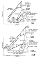
- FIG. 2 is a TS diagram thereof.
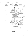
- FIG. 3 is a schematic illustration of a pair of organic Rankine cycle systems as combined in accordance with the present invention.
- FIG. 4 is a TS diagram thereof.
- FIG. 5 is an alternate embodiment of the present invention.
- FIG. 6 is a TS diagram thereof.
- FIG. 7 is another alternate embodiment of the present invention.
- FIG. 8 is a TS diagram thereof.
- a conventional type of organic Rankine cycle system is shown to include an evaporator/boiler 11 which receives waste heat from a source as described hereinabove.
- the heated working fluid passes to the turbine 12, where it is converted to motive power to drive a generator 13.
- the resulting lower temperature and pressure working fluid then passes to a condenser 14 where it is converted to a liquid, which is then pumped by the pump 16 back to the evaporator/boiler 11.
- a common working fluid is toluene.
- the working fluid has its temperature raised to around 274°C (525°F) after which it is passed to the turbine 12. After passing through the turbine 12, the temperature of the vapor drops down to about 149°C (300°F) before it is condensed and then pumped back to the evaporator/boiler 11.
- FIG. 2 Shown in Fig. 2 is a TS diagram of the organic rankine cycle system illustrated in Fig. 1 , using toluene as the working fluid.
- toluene is thermodynamically more efficient than systems with working fluids having lower critical temperatures.
- it is less cost effective and still leaves much to be desired in terms of efficiency.
- the reason for the higher cost of these higher temperature ORC systems is twofold: First, working fluids such as toluene, with high critical temperatures, allow operation at a higher evaporation temperature, which is relatively good for efficiency, but exhibit a very low density at ambient conditions, thus requiring large and expensive condensation equipment.
- a modified arrangement is shown to include a pair of organic Rankine cycle systems 20 and 25 that are combined in a manner which will now be described.
- An evaporator boiler or vapor generator 17 receives heat from a heat source 18 to produce relatively high pressure high temperature vapor which is passed to a turbine 19 to drive a generator 21. After passing through the turbine 19, the lower pressure, lower temperature vapor passes to the condenser/evaporator 23 where it is condensed into a liquid which is then pumped by the pump 24 to the vapor generator 17 to again be vaporized.
- an unrecuperated microturbine has an exit temperature of its exhaust gases of about 649°C (1200°F).
- This hot gas can be used to boil a high temperature organic fluid such as pentane, toluene or acetone in an ORC.
- the leaving temperature from the vapor generator 17 would be about 260°C (500°F)
- the temperature of the vapor leaving the turbine 19 and entering the condenser 23 would be about 149°C (300°F).
- the liquid toluene is at a temperature of about 135°C (275°F) as it leaves the condenser 23 and passes to the vapor generator 17 by way of the pump 24.
- the first ORC system i.e. the toluene loop
- the first ORC system is a high temperature system that extracts all the heat, either sensible such as from a hot gas or hot liquid, or latent such as from a condensing fluid such as steam in a refrigerant boiler/evaporator, creating high pressure and high temperature vapor.
- This high pressure vapor expands through the turbine 19 to a lower pressure with a saturation temperature corresponding to a level where a low cost/low temperature ORC system can be used to efficiently and cost effectively convert the lower temperature waste heat to power.
- the high temperature refrigerant still has positive pressure and a corresponding larger density in the condenser 23.
- the temperature of the toluene vapor entering the condenser/evaporator 23 is relatively high, its energy can now be used as a heat source for a vapor generator of a second ORC system 25, with the condenser/evaporator 23 acting both as the condenser for the first ORC system 20 and as the evaporator or boiler of the second ORC 25 system.
- the second ORC system therefore has a turbine 26, a generator 27, a condenser 28 and a pump 29.
- the organic working fluid for the second ORC must have relatively low boiling and condensation temperatures. Examples of organic working fluids that would be suitable for such a cycle are R245fa or isobutane. ,
- the temperature of the working fluid passing to the turbine 26 would be around 121°C (250°F), and that of the vapor passing to the condenser would be about 32°C (90°F).
- the refrigerant After condensation of the vapor, the refrigerant would be pumped to the condenser/evaporator 23 by the pump 29.
- FIG. 5 an alternate, nested arrangement is shown wherein, within the toluene circuit, the working fluid again passes from the boiler or vapor generator 17 to the turbine and then to a common heat exchanger 31.
- the heat exchanger 31 acts as an evaporator or boiler for the R245fa circuit, with the R245fa refrigerant passing from the boiler 31 to the turbine 26 to a condenser 28, the pump 29, and back to the boiler 31.
- the heat exchanger 31 acts as a desuperheater only within the toluene circuit, with a condenser 32 then being applied to complete the condensation process before the working fluid is passed by way of the pump 24 back to the boiler 17.
- the TS diagram for such a nested ORC cycle system is shown in Fig. 6 .
- the overall result of the nested ORC system is a more cost effective overall ORC system for high temperature waste heat sources.
- the increased cost effectiveness is obtained by increased power output and by reducing the size of the original desuperheater/condenser unit.
- FIG. 7 A further embodiment of the present invention is shown in Fig. 7 wherein the Fig. 5 embodiment is modified by the addition of a preheater 33 in the R245fa cycle as shown.
- the working fluid after passing through the condenser 28 and the pump 29, passes through the liquid preheater 33 using the waste heat source at lower temperatures (from 204°C (400°F) to 93°C (200°F)).
- the corresponding TS diagram is shown in Fig. 8 .
Landscapes
- Engineering & Computer Science (AREA)
- Chemical & Material Sciences (AREA)
- Combustion & Propulsion (AREA)
- Mechanical Engineering (AREA)
- General Engineering & Computer Science (AREA)
- Engine Equipment That Uses Special Cycles (AREA)
Description
- The United States Government has certain rights in this invention pursuant to Contract No. DE-FC02-00CH11060 between the Department of Energy and United Technologies Corporation.
- Power generation systems that provide low cost energy with minimum environmental impact, and that can be readily integrated into the existing power grids or rapidly sited as stand-alone units, can help solve critical power needs in many areas. Combustion engines such as microturbines or reciprocating engines can generate electricity at low cost with efficiencies of 25% to 40% using commonly available fuels such as gasoline, natural gas and diesel fuel. However, atmospheric emissions such as nitrogen oxides (NOx) and particulates can be a problem with reciprocating engines.
- One method to generate electricity from the waste heat of a combustion engine without increasing the output of emissions is to apply a bottoming cycle. Bottoming cycles use waste heat from such an engine and convert that thermal energy into electricity. Rankine cycles are often applied as the bottoming cycle for combustion engines. A fundamental organic Rankine cycle consists of a turbogenerator, a preheater/boiler, a condenser, and a liquid pump. Such a cycle can accept waste heat at temperatures somewhat above the boiling point of the organic working fluid chosen, and typically rejects heat to the ambient air or water at a temperature somewhat below the boiling point of the organic working fluid chosen. The choice of working fluid determines the temperature range/thermal efficiency characteristics of the cycle.
- Simple ORC Systems using one fluid are efficient and cost effective when transferring low temperature waste heat sources into electrical power, using hardware and working fluids similar to those used in the air conditioning/refrigeration industry. Examples are ORC systems using radial turbines derived from existing centrifugal compressors and working fluids such as refrigerant R245fa.
- For higher temperature waste heat streams, the most cost-effective ORC systems still operate at relatively low working fluid temperatures, allowing the continued use of HVAC derived equipment and common refrigerant. However these systems, although very cost-effective, do not take full advantage of the thermodynamic potential of the waste heat stream.
- The use of organic Rankine cycles to extract additional power from a steam Rankine cycle is known from
WO 98/06791 FR 903448 US 6857268 discloses a method of recovering power from an organic Rankine cycle. - According to a first aspect of the invention, there is provided a method of generating additional energy with an organic Rankine cycle system having in serial flow relationship a turbo generator for receiving a first organic fluid from a vapour generator, a first condenser, and a first pump for returning said first organic fluid to the vapour generator, characterized in that it comprises the steps of: providing a second organic Rankine cycle system having in serial flow relationship a second turbo generator for receiving a second organic working fluid from said condenser, a second condenser, and a second pump for returning said second organic working fluid to said condenser; wherein said first and second organic working fluids flow in heat exchange relationship through said first condenser.
- According to a second aspect of the invention, there is provided a combination of organic Rankine cycle systems comprising: a first organic Rankine cycle system having in serial flow relationship a first turbo generator for receiving a first organic working fluid from a vapour generator, a first condenser, and a first pump returning said first organic working fluid to the vapour generator; characterized in that it further comprises a second organic Rankine cycle system having in serial flow relationship a second turbo generator for receiving a second organic working fluid from said first condenser, a second condenser, and a second pump for returning said second organic working fluid to said first condenser; wherein said first and second organic working fluids are circulated in heat exchange relationship within said first condenser.
- Briefly, in accordance with one aspect of the invention, a pair of organic Rankine cycle (ORC) systems are combined, and a single common heat exchanger Is used as both the condenser for the first ORC system and as the evaporator for the second ORC system.
- By another aspect of the invention, the refrigerants of the two systems are chosen such that the condensation temperature of the first, higher temperature, system is a useable temperature for boiling the refrigerant of the second, lower temperature, system. In this way, greater efficiencies may be obtained and the waste heat loss to the atmosphere is substantially reduced.
- In accordance with another aspect of the invention, the single common heat exchanger is used to both desuperheat and condense the working fluid of the first ORC system.
- By another aspect of the invention, If a second heat exchanger is provided in the first ORC system, with the common heat exchanger acting to desuperheat the working fluid of the first ORC system, and the second condenser acting to condense the working fluid in the first ORC system.
- By yet another aspect of the invention, a preheater, using waste heat, is provided to preheat the working fluid in the second ORC system prior to its entry into the common heat exchanger.
- In the drawings as hereinafter described, preferred and modified embodiments are depicted; however various other modifications and alternate constructions can be made thereto without departing from the scope of the claims.
-
FIG. 1 is a schematic illustration of an organic Rankine cycle system in accordance with the prior art. -
FIG. 2 is a TS diagram thereof. -
FIG. 3 is a schematic illustration of a pair of organic Rankine cycle systems as combined in accordance with the present invention. -
FIG. 4 is a TS diagram thereof. -
FIG. 5 is an alternate embodiment of the present invention. -
FIG. 6 is a TS diagram thereof. -
FIG. 7 is another alternate embodiment of the present invention. -
FIG. 8 is a TS diagram thereof. - Referring now to
FIG. 1 , a conventional type of organic Rankine cycle system is shown to include an evaporator/boiler 11 which receives waste heat from a source as described hereinabove. The heated working fluid passes to theturbine 12, where it is converted to motive power to drive agenerator 13. The resulting lower temperature and pressure working fluid then passes to acondenser 14 where it is converted to a liquid, which is then pumped by thepump 16 back to the evaporator/boiler 11. - In such a typical system, a common working fluid is toluene. In the
vapor generator 11 the working fluid has its temperature raised to around 274°C (525°F) after which it is passed to theturbine 12. After passing through theturbine 12, the temperature of the vapor drops down to about 149°C (300°F) before it is condensed and then pumped back to the evaporator/boiler 11. - Shown in
Fig. 2 is a TS diagram of the organic rankine cycle system illustrated inFig. 1 , using toluene as the working fluid. As will be seen, because of the relatively high critical temperature, the toluene is thermodynamically more efficient than systems with working fluids having lower critical temperatures. However, it is less cost effective and still leaves much to be desired in terms of efficiency. The reason for the higher cost of these higher temperature ORC systems is twofold: First, working fluids such as toluene, with high critical temperatures, allow operation at a higher evaporation temperature, which is relatively good for efficiency, but exhibit a very low density at ambient conditions, thus requiring large and expensive condensation equipment. Secondly, the nature of such high critical temperature organic fluids is that the higher the turbine pressure ratio (typically larger than 25:1 in such a system), the more superheated the vapor that leaves the turbine. The thermal energy represented by the superheat of the vapor leaving the turbine is therefore not used for power generation and requires additional condenser surface for rejection to ambient. Accordingly, there is a substantial amount of lower temperature waste heat (i.e. the heat of the superheated low pressure vapor leaving the turbine) which is not converted into power, thereby limiting the turbine efficiency. - Referring now to
Fig. 3 , a modified arrangement is shown to include a pair of organic Rankinecycle systems vapor generator 17 receives heat from aheat source 18 to produce relatively high pressure high temperature vapor which is passed to aturbine 19 to drive agenerator 21. After passing through theturbine 19, the lower pressure, lower temperature vapor passes to the condenser/evaporator 23 where it is condensed into a liquid which is then pumped by thepump 24 to thevapor generator 17 to again be vaporized. - Typically an unrecuperated microturbine has an exit temperature of its exhaust gases of about 649°C (1200°F). This hot gas can be used to boil a high temperature organic fluid such as pentane, toluene or acetone in an ORC. If toluene is the working fluid, the leaving temperature from the
vapor generator 17 would be about 260°C (500°F), and the temperature of the vapor leaving theturbine 19 and entering thecondenser 23 would be about 149°C (300°F). After being condensed, the liquid toluene is at a temperature of about 135°C (275°F) as it leaves thecondenser 23 and passes to thevapor generator 17 by way of thepump 24. These temperatures and related entropies are shown in the TS diagram ofFIG. 4 . - In this cascaded ORC arrangement, the first ORC system (i.e. the toluene loop), is a high temperature system that extracts all the heat, either sensible such as from a hot gas or hot liquid, or latent such as from a condensing fluid such as steam in a refrigerant boiler/evaporator, creating high pressure and high temperature vapor. This high pressure vapor expands through the
turbine 19 to a lower pressure with a saturation temperature corresponding to a level where a low cost/low temperature ORC system can be used to efficiently and cost effectively convert the lower temperature waste heat to power. By doing this, the high temperature refrigerant still has positive pressure and a corresponding larger density in thecondenser 23. This results in a condenser with less pressure drop, better heat transfer and smaller size, all of which result in a mote cost effective ORC system.
The high pressure and larger density of the vapor exiting theturbine 19 also allows a smaller turbine design. A substantial reduction in cost can be obtained by these modifications. Further, the lower pressure ratio (i.e. 5:1) at theturbine 19 allows for higher turbine efficiencies. - Considering now that the temperature of the toluene vapor entering the condenser/
evaporator 23 is relatively high, its energy can now be used as a heat source for a vapor generator of asecond ORC system 25, with the condenser/evaporator 23 acting both as the condenser for thefirst ORC system 20 and as the evaporator or boiler of thesecond ORC 25 system. The second ORC system therefore has aturbine 26, agenerator 27, acondenser 28 and apump 29.
The organic working fluid for the second ORC must have relatively low boiling and condensation temperatures. Examples of organic working fluids that would be suitable for such a cycle are R245fa or isobutane. , - In the
second ORC system 25, with R245fa as the organic working fluid, the temperature of the working fluid passing to theturbine 26 would be around 121°C (250°F), and that of the vapor passing to the condenser would be about 32°C (90°F). After condensation of the vapor, the refrigerant would be pumped to the condenser/evaporator 23 by thepump 29. - Referring to
Fig. 5 , an alternate, nested arrangement is shown wherein, within the toluene circuit, the working fluid again passes from the boiler orvapor generator 17 to the turbine and then to acommon heat exchanger 31. Again, theheat exchanger 31 acts as an evaporator or boiler for the R245fa circuit, with the R245fa refrigerant passing from theboiler 31 to theturbine 26 to acondenser 28, thepump 29, and back to theboiler 31. However, unlike the condenser/evaporator 23 of theFig. 3 embodiment, theheat exchanger 31 acts as a desuperheater only within the toluene circuit, with acondenser 32 then being applied to complete the condensation process before the working fluid is passed by way of thepump 24 back to theboiler 17. The TS diagram for such a nested ORC cycle system is shown inFig. 6 . - In this nested arrangement a cost reduction is obtained by adding the low temperature, R245fa, ORC system in such a way that the overall system efficiency is increased. The major irreversibility (thermodynamic loss) of the simple cycle high temperature ORC system is the so-called desuperheat loss in the condenser. Organic fluids leave the turbine more superheated than they enter it. The larger the pressure ratio at the turbine, the stronger this effect. High temperature simple cycle ORC systems, although thermodynamically more efficient than the simple cycle low temperature ORC systems, reject a lot of moderate temperature waste heat that has to be rejected in the desuperheater/condenser. As a result, a relatively large condenser is required. In the nested ORC system, desuperheating is done in the low
temperature ORC evaporator 31. This increases the overall power output since this heat was previously rejected to ambient and is now used in a low temperature ORC system to generate power. A further advantage is that the size of the hightemperature ORC condenser 32 may be reduced. - Thus, the overall result of the nested ORC system is a more cost effective overall ORC system for high temperature waste heat sources. The increased cost effectiveness is obtained by increased power output and by reducing the size of the original desuperheater/condenser unit.
- Although the
Fig. 5 embodiment has been described in terms of use with two different refrigerants, it should be understood that the same refrigerant could be used in the two circuits. - A further embodiment of the present invention is shown in
Fig. 7 wherein theFig. 5 embodiment is modified by the addition of apreheater 33 in the R245fa cycle as shown. Here, the working fluid, after passing through thecondenser 28 and thepump 29, passes through theliquid preheater 33 using the waste heat source at lower temperatures (from 204°C (400°F) to 93°C (200°F)). The corresponding TS diagram is shown inFig. 8 . - While the present invention has been particularly shown and described with reference to preferred and alternate embodiments as illustrated in the drawings, it will be understood by one skilled in the art that various changes in detail may be effected therein without departing from the scope of the invention as defined by the claims.
Claims (17)
- A method of generating additional energy with an organic Rankine cycle system (20) having in serial flow relationship a turbo generator (19, 21) for receiving a first organic fluid from a vapour generator (17), a first condenser (23), and a first pump (24) for returning said first organic fluid to the vapour generator (17),
characterized in that it comprises the steps of:providing a second organic Rankine cycle system (25) having in serial flow relationship a second turbo generator (26, 27) for receiving a second organic working fluid from said condenser (23), a second condenser (28), and a second pump (29) for returning said second organic working fluid to said condenser (23);wherein said first and second organic working fluids flow in heat exchange relationship through said first condenser (23). - A method as set forth in claim 1 wherein said first organic working fluid is toluene.
- A method as set forth in claim 1 wherein said second organic working fluid is R245fa.
- A method as set forth in claim 1 and including the step of desuperheating and condensing the first organic fluid in said first condenser (23).
- A method as set forth in claim 1 and including the step of providing a third condenser (32) between said first condenser (31) and said first pump (24).
- A method as set forth in claim 5 and including the steps of desuperheating said first organic fluid in said first condenser (31) and condensing said first organic fluid in said third condenser (32).
- A method as set forth in claim 1 and including the step of providing a preheater (33) between said second pump (29) and said first condenser (23).
- A combination of organic Rankine cycle systems comprising:a first organic Rankine cycle system (20) having in serial flow relationship a first turbo generator (19, 21) for receiving a first organic working fluid from a vapour generator (17), a first condenser (23), and a first pump (24) returning said first organic working fluid to the vapour generator (17);characterized in that it further comprises a second organic Rankine cycle system (25) having in serial flow relationship a second turbo generator (26, 27) for receiving a second organic working fluid from said first condenser (23), a second condenser (28), and a second pump (29) for returning said second organic working fluid to said first condenser (23);wherein said first and second organic working fluids are circulated in heat exchange relationship within said first condenser (23).
- A combination as set forth in claim 8 wherein said first organic working fluid is toluene.
- A combination as set forth in claim 8 wherein said second organic working fluid Is R245fa.
- A combination as set forth in clam 8 wherein said first condenser (23) is operated to both desuperheat and condense said first organic working fluid.
- A combination as set forth in claim 8 and including a third condenser (32) between said first condenser (31) and said first pump (24).
- A combination as set forth in claim 12 wherein said first condenser (31) is applied to only desuperheat said first organic working fluid and said third condenser (32) is applied to condense said first organic working fluid.
- A combination as set forth in claim 8 and including a preheater (33) between said second pump (29) and said first condenser (23).
- A system for converting waste heat into energy comprising a combination of organic Rankine cycle systems as claimed in any of claims 8 to 14,
wherein said vapour generator (17) of said first organic Rankine cycle system (20) is in heat exchange relationship with said waste heat (18); and
wherein said first organic working fluid passes to said first condenser (23) at a first condensation temperature and further wherein said condensation temperature Is substantially above a boiling temperature of said second organic working fluid. - A method as set forth in claim 1 wherein said first and second organic working fluids are different types of fluids.
- A combination as set forth in claim 8 wherein said first and second organic working fluids are different types of fluids.
Applications Claiming Priority (1)
| Application Number | Priority Date | Filing Date | Title |
|---|---|---|---|
| PCT/US2005/010738 WO2006104490A1 (en) | 2005-03-29 | 2005-03-29 | Cascaded organic rankine cycles for waste heat utilization |
Publications (3)
| Publication Number | Publication Date |
|---|---|
| EP1869293A1 EP1869293A1 (en) | 2007-12-26 |
| EP1869293A4 EP1869293A4 (en) | 2008-06-25 |
| EP1869293B1 true EP1869293B1 (en) | 2013-05-08 |
Family
ID=37053668
Family Applications (1)
| Application Number | Title | Priority Date | Filing Date |
|---|---|---|---|
| EP05738495.0A Expired - Lifetime EP1869293B1 (en) | 2005-03-29 | 2005-03-29 | Cascaded organic rankine cycles for waste heat utilization |
Country Status (4)
| Country | Link |
|---|---|
| US (1) | US7942001B2 (en) |
| EP (1) | EP1869293B1 (en) |
| CN (1) | CN101248253B (en) |
| WO (1) | WO2006104490A1 (en) |
Cited By (1)
| Publication number | Priority date | Publication date | Assignee | Title |
|---|---|---|---|---|
| US11592009B2 (en) | 2021-04-02 | 2023-02-28 | Ice Thermal Harvesting, Llc | Systems and methods for generation of electrical power at a drilling rig |
Families Citing this family (100)
| Publication number | Priority date | Publication date | Assignee | Title |
|---|---|---|---|---|
| GB2442743A (en) * | 2006-10-12 | 2008-04-16 | Energetix Group Ltd | A Closed Cycle Heat Transfer Device |
| WO2008124890A1 (en) * | 2007-04-17 | 2008-10-23 | Innovative Design Technology Pty Limited | Energy transfer system |
| USRE46316E1 (en) * | 2007-04-17 | 2017-02-21 | Ormat Technologies, Inc. | Multi-level organic rankine cycle power system |
| US8561405B2 (en) | 2007-06-29 | 2013-10-22 | General Electric Company | System and method for recovering waste heat |
| JP5174905B2 (en) | 2007-07-27 | 2013-04-03 | ユナイテッド テクノロジーズ コーポレイション | Oil recovery from the organic Rankine cycle (ORC) system evaporator |
| ES2315191B1 (en) * | 2007-09-03 | 2010-01-11 | Diego Parra Gimenez | MULTI-PHASE COLD MOTOR THROUGH HOT AND COLD THERMODYNAMICS AND EFFICIENCY SUPERIOR TO 100%. AND COLD GENERATOR WITH A HIGH WORK COEFFICIENT (COP). |
| PL210568B1 (en) * | 2007-10-02 | 2012-02-29 | Univ West Pomeranian Szczecin Tech | Steam power plant driven by multiple sources |
| US20100263380A1 (en) * | 2007-10-04 | 2010-10-21 | United Technologies Corporation | Cascaded organic rankine cycle (orc) system using waste heat from a reciprocating engine |
| KR101010707B1 (en) | 2007-10-22 | 2011-01-24 | 김성완 | Waste Heat Recovery Generator |
| US8186161B2 (en) | 2007-12-14 | 2012-05-29 | General Electric Company | System and method for controlling an expansion system |
| US8375716B2 (en) | 2007-12-21 | 2013-02-19 | United Technologies Corporation | Operating a sub-sea organic Rankine cycle (ORC) system using individual pressure vessels |
| US8776517B2 (en) | 2008-03-31 | 2014-07-15 | Cummins Intellectual Properties, Inc. | Emissions-critical charge cooling using an organic rankine cycle |
| US7866157B2 (en) | 2008-05-12 | 2011-01-11 | Cummins Inc. | Waste heat recovery system with constant power output |
| KR100995959B1 (en) | 2008-05-28 | 2010-11-22 | 김성완 | Waste Heat Recovery Generator |
| US20100043433A1 (en) * | 2008-08-19 | 2010-02-25 | Kelly Patrick J | Heat Balancer for Steam-Based Generating Systems |
| US8596067B2 (en) * | 2008-12-19 | 2013-12-03 | Spx Corporation | Cooling tower apparatus and method with waste heat utilization |
| EP2372127A4 (en) * | 2008-12-26 | 2014-08-13 | Mitsubishi Heavy Ind Ltd | Control device for waste heat recovery system |
| CN101476494B (en) * | 2009-01-14 | 2011-02-02 | 牛东 | Energy conversion system for exhaust heat of heat engine |
| US20100242476A1 (en) * | 2009-03-30 | 2010-09-30 | General Electric Company | Combined heat and power cycle system |
| US20100242479A1 (en) * | 2009-03-30 | 2010-09-30 | General Electric Company | Tri-generation system using cascading organic rankine cycle |
| DE102009041550A1 (en) * | 2009-04-29 | 2010-11-04 | Daimler Ag | Heat utilization device and operating method |
| CN101899992A (en) * | 2009-05-31 | 2010-12-01 | 北京智慧剑科技发展有限责任公司 | Micro-gas generator with closed cavity |
| US20110000210A1 (en) * | 2009-07-01 | 2011-01-06 | Miles Mark W | Integrated System for Using Thermal Energy Conversion |
| US8544274B2 (en) * | 2009-07-23 | 2013-10-01 | Cummins Intellectual Properties, Inc. | Energy recovery system using an organic rankine cycle |
| CN101614139A (en) * | 2009-07-31 | 2009-12-30 | 王世英 | Multicycle power generation thermodynamic system |
| US8627663B2 (en) | 2009-09-02 | 2014-01-14 | Cummins Intellectual Properties, Inc. | Energy recovery system and method using an organic rankine cycle with condenser pressure regulation |
| US8459029B2 (en) | 2009-09-28 | 2013-06-11 | General Electric Company | Dual reheat rankine cycle system and method thereof |
| US8459030B2 (en) * | 2009-09-30 | 2013-06-11 | General Electric Company | Heat engine and method for operating the same |
| US20110083437A1 (en) * | 2009-10-13 | 2011-04-14 | General Electric Company | Rankine cycle system |
| US8193659B2 (en) * | 2009-11-19 | 2012-06-05 | Ormat Technologies, Inc. | Power system |
| TWM377472U (en) * | 2009-12-04 | 2010-04-01 | Cheng-Chun Lee | Steam turbine electricity generation system with features of latent heat recovery |
| IT1400467B1 (en) * | 2010-03-25 | 2013-06-11 | Nasini | PLANT FOR ENERGY PRODUCTION BASED ON THE RANKINE CYCLE WITH ORGANIC FLUID. |
| US20110308576A1 (en) * | 2010-06-18 | 2011-12-22 | General Electric Company | Hybrid photovoltaic system and method thereof |
| US9046006B2 (en) * | 2010-06-21 | 2015-06-02 | Paccar Inc | Dual cycle rankine waste heat recovery cycle |
| DE112011102672B4 (en) | 2010-08-09 | 2022-12-29 | Cummins Intellectual Properties, Inc. | Waste heat recovery system and internal combustion engine system for capturing energy after engine aftertreatment systems |
| US20120031096A1 (en) * | 2010-08-09 | 2012-02-09 | Uop Llc | Low Grade Heat Recovery from Process Streams for Power Generation |
| WO2012021757A2 (en) | 2010-08-11 | 2012-02-16 | Cummins Intellectual Property, Inc. | Split radiator design for heat rejection optimization for a waste heat recovery system |
| EP2603673B1 (en) | 2010-08-13 | 2019-12-25 | Cummins Intellectual Properties, Inc. | Rankine cycle condenser pressure control using an energy conversion device bypass valve |
| US8474262B2 (en) * | 2010-08-24 | 2013-07-02 | Yakov Regelman | Advanced tandem organic rankine cycle |
| CN101929360B (en) * | 2010-09-02 | 2013-08-21 | 上海交通大学 | Medium-low temperature heat source generating set based on energy cascade utilization and thermal circulation method thereof |
| US8904791B2 (en) * | 2010-11-19 | 2014-12-09 | General Electric Company | Rankine cycle integrated with organic rankine cycle and absorption chiller cycle |
| CN102003229B (en) * | 2010-11-19 | 2013-10-02 | 北京工业大学 | Control system and method for generating power by waste heat of diesel engine |
| US8826662B2 (en) | 2010-12-23 | 2014-09-09 | Cummins Intellectual Property, Inc. | Rankine cycle system and method |
| DE112011104516B4 (en) | 2010-12-23 | 2017-01-19 | Cummins Intellectual Property, Inc. | System and method for regulating EGR cooling using a Rankine cycle |
| DE102010056272A1 (en) * | 2010-12-24 | 2012-06-28 | Robert Bosch Gmbh | Waste heat utilization system |
| DE102012000100A1 (en) | 2011-01-06 | 2012-07-12 | Cummins Intellectual Property, Inc. | Rankine cycle-HEAT USE SYSTEM |
| WO2012096958A1 (en) | 2011-01-10 | 2012-07-19 | Cummins Intellectual Property, Inc. | Rankine cycle waste heat recovery system |
| EP2665907B1 (en) | 2011-01-20 | 2017-05-10 | Cummins Intellectual Properties, Inc. | Rankine cycle waste heat recovery system and method with improved egr temperature control |
| US9816402B2 (en) * | 2011-01-28 | 2017-11-14 | Johnson Controls Technology Company | Heat recovery system series arrangements |
| WO2012110987A1 (en) * | 2011-02-19 | 2012-08-23 | Devendra Purohit | Environmental energy conversion device |
| SE1150169A1 (en) * | 2011-02-25 | 2012-06-26 | Scania Cv Ab | Systems for converting thermal energy into mechanical energy in a vehicle |
| US8707914B2 (en) | 2011-02-28 | 2014-04-29 | Cummins Intellectual Property, Inc. | Engine having integrated waste heat recovery |
| JP2014514488A (en) * | 2011-03-25 | 2014-06-19 | スリーエム イノベイティブ プロパティズ カンパニー | Fluorinated oxiranes as organic Rankine cycle working fluid and methods of use thereof |
| EP4375346A3 (en) | 2011-08-19 | 2024-07-24 | The Chemours Company FC, LLC | Processes for organic rankine cycles for generating mechanical energy from heat |
| DE102011054584A1 (en) | 2011-10-18 | 2013-04-18 | Frank Ricken | Method and device for providing electricity |
| US10690121B2 (en) * | 2011-10-31 | 2020-06-23 | University Of South Florida | Integrated cascading cycle solar thermal plants |
| US20130160449A1 (en) * | 2011-12-22 | 2013-06-27 | Frederick J. Cogswell | Cascaded organic rankine cycle system |
| US9018778B2 (en) | 2012-01-04 | 2015-04-28 | General Electric Company | Waste heat recovery system generator varnishing |
| US9024460B2 (en) | 2012-01-04 | 2015-05-05 | General Electric Company | Waste heat recovery system generator encapsulation |
| US8984884B2 (en) * | 2012-01-04 | 2015-03-24 | General Electric Company | Waste heat recovery systems |
| US20130174552A1 (en) * | 2012-01-06 | 2013-07-11 | United Technologies Corporation | Non-azeotropic working fluid mixtures for rankine cycle systems |
| EP2809892B1 (en) * | 2012-02-02 | 2019-01-02 | Bitzer Us, Inc. | Improved heat utilization in orc systems |
| JP5902512B2 (en) * | 2012-03-02 | 2016-04-13 | ヤンマー株式会社 | Waste heat recovery Rankine cycle system |
| DE102012210803A1 (en) * | 2012-06-26 | 2014-01-02 | Energy Intelligence Lab Gmbh | Device for generating electrical energy by means of an ORC circuit |
| US8893495B2 (en) | 2012-07-16 | 2014-11-25 | Cummins Intellectual Property, Inc. | Reversible waste heat recovery system and method |
| US9322300B2 (en) * | 2012-07-24 | 2016-04-26 | Access Energy Llc | Thermal cycle energy and pumping recovery system |
| US9115603B2 (en) | 2012-07-24 | 2015-08-25 | Electratherm, Inc. | Multiple organic Rankine cycle system and method |
| DE102012217339A1 (en) * | 2012-09-25 | 2014-03-27 | Duerr Cyplan Ltd. | Network for transporting heat |
| CN102900562A (en) * | 2012-09-28 | 2013-01-30 | 北京工业大学 | Organic Rankine cycle system for recycling engine exhaust waste heat and changing heat change area of evaporator |
| US9140209B2 (en) | 2012-11-16 | 2015-09-22 | Cummins Inc. | Rankine cycle waste heat recovery system |
| CN103075251B (en) * | 2013-01-27 | 2015-10-21 | 南京瑞柯徕姆环保科技有限公司 | Boulez pauses-steam-extracting type steam Rankine combined cycle generating unit |
| CN103089442B (en) * | 2013-01-27 | 2015-10-21 | 南京瑞柯徕姆环保科技有限公司 | Boulez pauses-steam Rankine-organic Rankine combined cycle generating unit |
| US9540961B2 (en) | 2013-04-25 | 2017-01-10 | Access Energy Llc | Heat sources for thermal cycles |
| CN103277147A (en) * | 2013-05-24 | 2013-09-04 | 成都昊特新能源技术股份有限公司 | Dual-power ORC power generation system and power generation method of same |
| US9845711B2 (en) | 2013-05-24 | 2017-12-19 | Cummins Inc. | Waste heat recovery system |
| CA2885583C (en) | 2013-06-07 | 2017-09-26 | Her Majesty The Queen In Right Of Canada As Represented By The Ministeof Natural Resources | Hybrid rankine cycle |
| CN104279013B (en) * | 2013-07-08 | 2016-06-01 | 北京华航盛世能源技术有限公司 | The ORC (organic Rankine cycle) low-temperature afterheat generating system of a kind of optimization |
| WO2015017873A2 (en) | 2013-08-02 | 2015-02-05 | Gill Martin Gordon | Multi-cycle power generator |
| US10302335B2 (en) * | 2014-06-10 | 2019-05-28 | Lg Chem, Ltd. | Heat recovery apparatus |
| RU2657068C2 (en) * | 2015-11-13 | 2018-06-08 | Общество с ограниченной ответственностью "Элген Технологии", ООО "Элген Технологии" | Installation for electrical energy generation for utilization of heat of smoke and exhaust gases |
| AU2016359565B2 (en) * | 2015-11-24 | 2021-11-04 | Yakov Elgart | Method and system of combined power plant for waste heat conversion to electrical energy, heating and cooling |
| ITUA20163546A1 (en) * | 2016-05-18 | 2017-11-18 | Turboden Srl | RANKINE ORGANIC COGENERATIVE PLANT SYSTEM |
| IT201600078847A1 (en) * | 2016-07-27 | 2018-01-27 | Turboden Spa | CYCLE WITH OPTIMIZED DIRECT EXCHANGE |
| CN111699302A (en) * | 2017-12-18 | 2020-09-22 | 艾赛杰国际有限公司 | Method, apparatus and thermodynamic cycle for generating power from a variable temperature heat source |
| CN109751095A (en) * | 2019-01-16 | 2019-05-14 | 南京航空航天大学 | The water-electricity cogeneration system and working method of cascade utilization fume waste heat concentrate solution |
| CN110159377B (en) * | 2019-05-31 | 2024-11-26 | 深圳大学 | ORC magnetic levitation power generation system for step-by-step utilization of medium and low temperature geothermal fluids |
| CN110131115B (en) * | 2019-05-31 | 2024-06-18 | 深圳大学 | Medium and low temperature geothermal ORC magnetic levitation composite cascade power generation system |
| US11364449B2 (en) * | 2020-07-15 | 2022-06-21 | Energy Integration, Inc. | Methods and systems for optimizing mechanical vapor compression and/or thermal vapor compression within multiple-stage processes |
| US12312981B2 (en) | 2021-04-02 | 2025-05-27 | Ice Thermal Harvesting, Llc | Systems and methods utilizing gas temperature as a power source |
| US11293414B1 (en) | 2021-04-02 | 2022-04-05 | Ice Thermal Harvesting, Llc | Systems and methods for generation of electrical power in an organic rankine cycle operation |
| US11644015B2 (en) | 2021-04-02 | 2023-05-09 | Ice Thermal Harvesting, Llc | Systems and methods for generation of electrical power at a drilling rig |
| US11480074B1 (en) | 2021-04-02 | 2022-10-25 | Ice Thermal Harvesting, Llc | Systems and methods utilizing gas temperature as a power source |
| US11359576B1 (en) | 2021-04-02 | 2022-06-14 | Ice Thermal Harvesting, Llc | Systems and methods utilizing gas temperature as a power source |
| US11493029B2 (en) | 2021-04-02 | 2022-11-08 | Ice Thermal Harvesting, Llc | Systems and methods for generation of electrical power at a drilling rig |
| US11486370B2 (en) | 2021-04-02 | 2022-11-01 | Ice Thermal Harvesting, Llc | Modular mobile heat generation unit for generation of geothermal power in organic Rankine cycle operations |
| WO2022213112A1 (en) * | 2021-04-02 | 2022-10-06 | Ice Thermal Harvesting, Llc | Systems and methods utilizing gas temperature as a power source |
| US11421663B1 (en) | 2021-04-02 | 2022-08-23 | Ice Thermal Harvesting, Llc | Systems and methods for generation of electrical power in an organic Rankine cycle operation |
| US11255315B1 (en) | 2021-04-02 | 2022-02-22 | Ice Thermal Harvesting, Llc | Controller for controlling generation of geothermal power in an organic Rankine cycle operation during hydrocarbon production |
| US12534990B2 (en) | 2022-12-29 | 2026-01-27 | Ice Thermal Harvesting, Llc | Power generation assemblies for hydraulic fracturing systems and methods |
| US12180861B1 (en) | 2022-12-30 | 2024-12-31 | Ice Thermal Harvesting, Llc | Systems and methods to utilize heat carriers in conversion of thermal energy |
Family Cites Families (15)
| Publication number | Priority date | Publication date | Assignee | Title |
|---|---|---|---|---|
| FR903448A (en) | 1943-11-08 | 1945-10-04 | Improvements to steam motive power installations | |
| US3234734A (en) * | 1962-06-25 | 1966-02-15 | Monsanto Co | Power generation |
| US3393515A (en) | 1965-09-16 | 1968-07-23 | Israel State | Power generating units |
| US3908381A (en) * | 1974-11-20 | 1975-09-30 | Sperry Rand Corp | Geothermal energy conversion system for maximum energy extraction |
| US4760705A (en) * | 1983-05-31 | 1988-08-02 | Ormat Turbines Ltd. | Rankine cycle power plant with improved organic working fluid |
| US4996846A (en) * | 1990-02-12 | 1991-03-05 | Ormat Inc. | Method of and apparatus for retrofitting geothermal power plants |
| FI913367A0 (en) * | 1991-07-11 | 1991-07-11 | High Speed Tech Ltd Oy | FOERFARANDE OCH ANORDNING FOER ATT FOERBAETTRA NYTTIGHETSFOERHAOLLANDE AV EN ORC-PROCESS. |
| AU4052097A (en) | 1996-08-14 | 1998-03-06 | Allied-Signal Inc. | Pentafluoropropanes and hexafluoropropanes as working fluids for power generation |
| US6052997A (en) | 1998-09-03 | 2000-04-25 | Rosenblatt; Joel H. | Reheat cycle for a sub-ambient turbine system |
| US6571548B1 (en) * | 1998-12-31 | 2003-06-03 | Ormat Industries Ltd. | Waste heat recovery in an organic energy converter using an intermediate liquid cycle |
| US6960839B2 (en) * | 2000-07-17 | 2005-11-01 | Ormat Technologies, Inc. | Method of and apparatus for producing power from a heat source |
| US6857268B2 (en) | 2002-07-22 | 2005-02-22 | Wow Energy, Inc. | Cascading closed loop cycle (CCLC) |
| DE10355782B4 (en) | 2003-11-26 | 2006-04-27 | Maxxtec Ag | Apparatus and method for carrying out a thermal cycle |
| US7100380B2 (en) * | 2004-02-03 | 2006-09-05 | United Technologies Corporation | Organic rankine cycle fluid |
| US7290393B2 (en) | 2004-05-06 | 2007-11-06 | Utc Power Corporation | Method for synchronizing an induction generator of an ORC plant to a grid |
-
2005
- 2005-03-29 WO PCT/US2005/010738 patent/WO2006104490A1/en not_active Ceased
- 2005-03-29 US US11/886,281 patent/US7942001B2/en not_active Expired - Fee Related
- 2005-03-29 CN CN200580049305.0A patent/CN101248253B/en not_active Expired - Fee Related
- 2005-03-29 EP EP05738495.0A patent/EP1869293B1/en not_active Expired - Lifetime
Cited By (1)
| Publication number | Priority date | Publication date | Assignee | Title |
|---|---|---|---|---|
| US11592009B2 (en) | 2021-04-02 | 2023-02-28 | Ice Thermal Harvesting, Llc | Systems and methods for generation of electrical power at a drilling rig |
Also Published As
| Publication number | Publication date |
|---|---|
| CN101248253A (en) | 2008-08-20 |
| EP1869293A1 (en) | 2007-12-26 |
| EP1869293A4 (en) | 2008-06-25 |
| CN101248253B (en) | 2010-12-29 |
| US7942001B2 (en) | 2011-05-17 |
| WO2006104490A1 (en) | 2006-10-05 |
| US20080168772A1 (en) | 2008-07-17 |
Similar Documents
| Publication | Publication Date | Title |
|---|---|---|
| EP1869293B1 (en) | Cascaded organic rankine cycles for waste heat utilization | |
| AU2010221785B2 (en) | Dual reheat rankine cycle system and method thereof | |
| US8561405B2 (en) | System and method for recovering waste heat | |
| CN102695860B (en) | For reclaiming compound closed-loop heat cycle system and the method thereof of used heat | |
| JP4388067B2 (en) | Method and apparatus for performing a thermodynamic cycle | |
| US9038391B2 (en) | System and method for recovery of waste heat from dual heat sources | |
| US20100319346A1 (en) | System for recovering waste heat | |
| US20100326076A1 (en) | Optimized system for recovering waste heat | |
| US20100242476A1 (en) | Combined heat and power cycle system | |
| KR20070116106A (en) | Cascaded Organic Rankine Cycle to Use Waste Heat | |
| Haselbacher et al. | Turbomachines for application in LOTHECO powerplants (turbomachines for LOTHECO) |
Legal Events
| Date | Code | Title | Description |
|---|---|---|---|
| PUAI | Public reference made under article 153(3) epc to a published international application that has entered the european phase |
Free format text: ORIGINAL CODE: 0009012 |
|
| 17P | Request for examination filed |
Effective date: 20071029 |
|
| AK | Designated contracting states |
Kind code of ref document: A1 Designated state(s): AT BE BG CH CY CZ DE DK EE ES FI FR GB GR HU IE IS IT LI LT LU MC NL PL PT RO SE SI SK TR |
|
| A4 | Supplementary search report drawn up and despatched |
Effective date: 20080528 |
|
| RIC1 | Information provided on ipc code assigned before grant |
Ipc: F01K 23/04 20060101ALI20080522BHEP Ipc: F01K 25/08 20060101AFI20061019BHEP |
|
| DAX | Request for extension of the european patent (deleted) | ||
| 17Q | First examination report despatched |
Effective date: 20120223 |
|
| GRAP | Despatch of communication of intention to grant a patent |
Free format text: ORIGINAL CODE: EPIDOSNIGR1 |
|
| GRAS | Grant fee paid |
Free format text: ORIGINAL CODE: EPIDOSNIGR3 |
|
| GRAA | (expected) grant |
Free format text: ORIGINAL CODE: 0009210 |
|
| AK | Designated contracting states |
Kind code of ref document: B1 Designated state(s): AT BE BG CH CY CZ DE DK EE ES FI FR GB GR HU IE IS IT LI LT LU MC NL PL PT RO SE SI SK TR |
|
| REG | Reference to a national code |
Ref country code: GB Ref legal event code: FG4D |
|
| REG | Reference to a national code |
Ref country code: CH Ref legal event code: EP Ref country code: AT Ref legal event code: REF Ref document number: 611213 Country of ref document: AT Kind code of ref document: T Effective date: 20130515 |
|
| REG | Reference to a national code |
Ref country code: IE Ref legal event code: FG4D |
|
| REG | Reference to a national code |
Ref country code: DE Ref legal event code: R096 Ref document number: 602005039492 Country of ref document: DE Effective date: 20130704 |
|
| REG | Reference to a national code |
Ref country code: AT Ref legal event code: MK05 Ref document number: 611213 Country of ref document: AT Kind code of ref document: T Effective date: 20130508 |
|
| REG | Reference to a national code |
Ref country code: LT Ref legal event code: MG4D |
|
| REG | Reference to a national code |
Ref country code: NL Ref legal event code: VDEP Effective date: 20130508 |
|
| PG25 | Lapsed in a contracting state [announced via postgrant information from national office to epo] |
Ref country code: LT Free format text: LAPSE BECAUSE OF FAILURE TO SUBMIT A TRANSLATION OF THE DESCRIPTION OR TO PAY THE FEE WITHIN THE PRESCRIBED TIME-LIMIT Effective date: 20130508 Ref country code: ES Free format text: LAPSE BECAUSE OF FAILURE TO SUBMIT A TRANSLATION OF THE DESCRIPTION OR TO PAY THE FEE WITHIN THE PRESCRIBED TIME-LIMIT Effective date: 20130819 Ref country code: FI Free format text: LAPSE BECAUSE OF FAILURE TO SUBMIT A TRANSLATION OF THE DESCRIPTION OR TO PAY THE FEE WITHIN THE PRESCRIBED TIME-LIMIT Effective date: 20130508 Ref country code: AT Free format text: LAPSE BECAUSE OF FAILURE TO SUBMIT A TRANSLATION OF THE DESCRIPTION OR TO PAY THE FEE WITHIN THE PRESCRIBED TIME-LIMIT Effective date: 20130508 Ref country code: SI Free format text: LAPSE BECAUSE OF FAILURE TO SUBMIT A TRANSLATION OF THE DESCRIPTION OR TO PAY THE FEE WITHIN THE PRESCRIBED TIME-LIMIT Effective date: 20130508 Ref country code: IS Free format text: LAPSE BECAUSE OF FAILURE TO SUBMIT A TRANSLATION OF THE DESCRIPTION OR TO PAY THE FEE WITHIN THE PRESCRIBED TIME-LIMIT Effective date: 20130908 Ref country code: GR Free format text: LAPSE BECAUSE OF FAILURE TO SUBMIT A TRANSLATION OF THE DESCRIPTION OR TO PAY THE FEE WITHIN THE PRESCRIBED TIME-LIMIT Effective date: 20130809 Ref country code: PT Free format text: LAPSE BECAUSE OF FAILURE TO SUBMIT A TRANSLATION OF THE DESCRIPTION OR TO PAY THE FEE WITHIN THE PRESCRIBED TIME-LIMIT Effective date: 20130909 Ref country code: SE Free format text: LAPSE BECAUSE OF FAILURE TO SUBMIT A TRANSLATION OF THE DESCRIPTION OR TO PAY THE FEE WITHIN THE PRESCRIBED TIME-LIMIT Effective date: 20130508 |
|
| PG25 | Lapsed in a contracting state [announced via postgrant information from national office to epo] |
Ref country code: PL Free format text: LAPSE BECAUSE OF FAILURE TO SUBMIT A TRANSLATION OF THE DESCRIPTION OR TO PAY THE FEE WITHIN THE PRESCRIBED TIME-LIMIT Effective date: 20130508 Ref country code: CY Free format text: LAPSE BECAUSE OF FAILURE TO SUBMIT A TRANSLATION OF THE DESCRIPTION OR TO PAY THE FEE WITHIN THE PRESCRIBED TIME-LIMIT Effective date: 20130508 Ref country code: BG Free format text: LAPSE BECAUSE OF FAILURE TO SUBMIT A TRANSLATION OF THE DESCRIPTION OR TO PAY THE FEE WITHIN THE PRESCRIBED TIME-LIMIT Effective date: 20130808 |
|
| PG25 | Lapsed in a contracting state [announced via postgrant information from national office to epo] |
Ref country code: CZ Free format text: LAPSE BECAUSE OF FAILURE TO SUBMIT A TRANSLATION OF THE DESCRIPTION OR TO PAY THE FEE WITHIN THE PRESCRIBED TIME-LIMIT Effective date: 20130508 Ref country code: DK Free format text: LAPSE BECAUSE OF FAILURE TO SUBMIT A TRANSLATION OF THE DESCRIPTION OR TO PAY THE FEE WITHIN THE PRESCRIBED TIME-LIMIT Effective date: 20130508 Ref country code: SK Free format text: LAPSE BECAUSE OF FAILURE TO SUBMIT A TRANSLATION OF THE DESCRIPTION OR TO PAY THE FEE WITHIN THE PRESCRIBED TIME-LIMIT Effective date: 20130508 Ref country code: EE Free format text: LAPSE BECAUSE OF FAILURE TO SUBMIT A TRANSLATION OF THE DESCRIPTION OR TO PAY THE FEE WITHIN THE PRESCRIBED TIME-LIMIT Effective date: 20130508 Ref country code: BE Free format text: LAPSE BECAUSE OF FAILURE TO SUBMIT A TRANSLATION OF THE DESCRIPTION OR TO PAY THE FEE WITHIN THE PRESCRIBED TIME-LIMIT Effective date: 20130508 |
|
| PG25 | Lapsed in a contracting state [announced via postgrant information from national office to epo] |
Ref country code: NL Free format text: LAPSE BECAUSE OF FAILURE TO SUBMIT A TRANSLATION OF THE DESCRIPTION OR TO PAY THE FEE WITHIN THE PRESCRIBED TIME-LIMIT Effective date: 20130508 Ref country code: RO Free format text: LAPSE BECAUSE OF FAILURE TO SUBMIT A TRANSLATION OF THE DESCRIPTION OR TO PAY THE FEE WITHIN THE PRESCRIBED TIME-LIMIT Effective date: 20130508 Ref country code: IT Free format text: LAPSE BECAUSE OF FAILURE TO SUBMIT A TRANSLATION OF THE DESCRIPTION OR TO PAY THE FEE WITHIN THE PRESCRIBED TIME-LIMIT Effective date: 20130508 |
|
| PLBE | No opposition filed within time limit |
Free format text: ORIGINAL CODE: 0009261 |
|
| STAA | Information on the status of an ep patent application or granted ep patent |
Free format text: STATUS: NO OPPOSITION FILED WITHIN TIME LIMIT |
|
| 26N | No opposition filed |
Effective date: 20140211 |
|
| REG | Reference to a national code |
Ref country code: DE Ref legal event code: R097 Ref document number: 602005039492 Country of ref document: DE Effective date: 20140211 |
|
| PG25 | Lapsed in a contracting state [announced via postgrant information from national office to epo] |
Ref country code: LU Free format text: LAPSE BECAUSE OF FAILURE TO SUBMIT A TRANSLATION OF THE DESCRIPTION OR TO PAY THE FEE WITHIN THE PRESCRIBED TIME-LIMIT Effective date: 20140329 |
|
| REG | Reference to a national code |
Ref country code: CH Ref legal event code: PL |
|
| REG | Reference to a national code |
Ref country code: FR Ref legal event code: ST Effective date: 20141128 |
|
| REG | Reference to a national code |
Ref country code: IE Ref legal event code: MM4A |
|
| PG25 | Lapsed in a contracting state [announced via postgrant information from national office to epo] |
Ref country code: CH Free format text: LAPSE BECAUSE OF NON-PAYMENT OF DUE FEES Effective date: 20140331 Ref country code: IE Free format text: LAPSE BECAUSE OF NON-PAYMENT OF DUE FEES Effective date: 20140329 Ref country code: FR Free format text: LAPSE BECAUSE OF NON-PAYMENT OF DUE FEES Effective date: 20140331 Ref country code: LI Free format text: LAPSE BECAUSE OF NON-PAYMENT OF DUE FEES Effective date: 20140331 |
|
| PG25 | Lapsed in a contracting state [announced via postgrant information from national office to epo] |
Ref country code: MC Free format text: LAPSE BECAUSE OF FAILURE TO SUBMIT A TRANSLATION OF THE DESCRIPTION OR TO PAY THE FEE WITHIN THE PRESCRIBED TIME-LIMIT Effective date: 20130508 |
|
| PG25 | Lapsed in a contracting state [announced via postgrant information from national office to epo] |
Ref country code: TR Free format text: LAPSE BECAUSE OF FAILURE TO SUBMIT A TRANSLATION OF THE DESCRIPTION OR TO PAY THE FEE WITHIN THE PRESCRIBED TIME-LIMIT Effective date: 20130508 Ref country code: HU Free format text: LAPSE BECAUSE OF FAILURE TO SUBMIT A TRANSLATION OF THE DESCRIPTION OR TO PAY THE FEE WITHIN THE PRESCRIBED TIME-LIMIT; INVALID AB INITIO Effective date: 20050329 |
|
| REG | Reference to a national code |
Ref country code: DE Ref legal event code: R082 Ref document number: 602005039492 Country of ref document: DE Representative=s name: SCHMITT-NILSON SCHRAUD WAIBEL WOHLFROM PATENTA, DE |
|
| PGFP | Annual fee paid to national office [announced via postgrant information from national office to epo] |
Ref country code: DE Payment date: 20180219 Year of fee payment: 14 Ref country code: GB Payment date: 20180226 Year of fee payment: 14 |
|
| REG | Reference to a national code |
Ref country code: DE Ref legal event code: R119 Ref document number: 602005039492 Country of ref document: DE |
|
| GBPC | Gb: european patent ceased through non-payment of renewal fee |
Effective date: 20190329 |
|
| PG25 | Lapsed in a contracting state [announced via postgrant information from national office to epo] |
Ref country code: GB Free format text: LAPSE BECAUSE OF NON-PAYMENT OF DUE FEES Effective date: 20190329 Ref country code: DE Free format text: LAPSE BECAUSE OF NON-PAYMENT OF DUE FEES Effective date: 20191001 |