EP2222352B1 - Luftseparator für ein ophthalmisches operationssystem - Google Patents
Luftseparator für ein ophthalmisches operationssystem Download PDFInfo
- Publication number
- EP2222352B1 EP2222352B1 EP08860301.4A EP08860301A EP2222352B1 EP 2222352 B1 EP2222352 B1 EP 2222352B1 EP 08860301 A EP08860301 A EP 08860301A EP 2222352 B1 EP2222352 B1 EP 2222352B1
- Authority
- EP
- European Patent Office
- Prior art keywords
- flow channel
- sectional area
- cross
- oriented
- diagonally
- Prior art date
- Legal status (The legal status is an assumption and is not a legal conclusion. Google has not performed a legal analysis and makes no representation as to the accuracy of the status listed.)
- Not-in-force
Links
- 238000011144 upstream manufacturing Methods 0.000 claims description 45
- 239000012530 fluid Substances 0.000 claims description 33
- 238000005259 measurement Methods 0.000 claims description 20
- 230000000630 rising effect Effects 0.000 claims description 5
- 239000007788 liquid Substances 0.000 claims description 4
- 238000000926 separation method Methods 0.000 claims description 3
- 238000004891 communication Methods 0.000 description 3
- 230000007704 transition Effects 0.000 description 3
- 230000005355 Hall effect Effects 0.000 description 2
- FAPWRFPIFSIZLT-UHFFFAOYSA-M Sodium chloride Chemical compound [Na+].[Cl-] FAPWRFPIFSIZLT-UHFFFAOYSA-M 0.000 description 2
- 238000000034 method Methods 0.000 description 2
- 238000012986 modification Methods 0.000 description 2
- 230000004048 modification Effects 0.000 description 2
- 239000000523 sample Substances 0.000 description 2
- 239000004020 conductor Substances 0.000 description 1
- 238000010276 construction Methods 0.000 description 1
- 238000011161 development Methods 0.000 description 1
- 230000000694 effects Effects 0.000 description 1
- 238000001914 filtration Methods 0.000 description 1
- 230000001939 inductive effect Effects 0.000 description 1
- 239000003978 infusion fluid Substances 0.000 description 1
- 238000002406 microsurgery Methods 0.000 description 1
- 238000001356 surgical procedure Methods 0.000 description 1
Images

Classifications
-
- A—HUMAN NECESSITIES
- A61—MEDICAL OR VETERINARY SCIENCE; HYGIENE
- A61M—DEVICES FOR INTRODUCING MEDIA INTO, OR ONTO, THE BODY; DEVICES FOR TRANSDUCING BODY MEDIA OR FOR TAKING MEDIA FROM THE BODY; DEVICES FOR PRODUCING OR ENDING SLEEP OR STUPOR
- A61M1/00—Suction or pumping devices for medical purposes; Devices for carrying-off, for treatment of, or for carrying-over, body-liquids; Drainage systems
- A61M1/71—Suction drainage systems
- A61M1/73—Suction drainage systems comprising sensors or indicators for physical values
- A61M1/734—Visual indicating means for flow
-
- A—HUMAN NECESSITIES
- A61—MEDICAL OR VETERINARY SCIENCE; HYGIENE
- A61M—DEVICES FOR INTRODUCING MEDIA INTO, OR ONTO, THE BODY; DEVICES FOR TRANSDUCING BODY MEDIA OR FOR TAKING MEDIA FROM THE BODY; DEVICES FOR PRODUCING OR ENDING SLEEP OR STUPOR
- A61M1/00—Suction or pumping devices for medical purposes; Devices for carrying-off, for treatment of, or for carrying-over, body-liquids; Drainage systems
- A61M1/71—Suction drainage systems
- A61M1/73—Suction drainage systems comprising sensors or indicators for physical values
-
- A—HUMAN NECESSITIES
- A61—MEDICAL OR VETERINARY SCIENCE; HYGIENE
- A61M—DEVICES FOR INTRODUCING MEDIA INTO, OR ONTO, THE BODY; DEVICES FOR TRANSDUCING BODY MEDIA OR FOR TAKING MEDIA FROM THE BODY; DEVICES FOR PRODUCING OR ENDING SLEEP OR STUPOR
- A61M1/00—Suction or pumping devices for medical purposes; Devices for carrying-off, for treatment of, or for carrying-over, body-liquids; Drainage systems
- A61M1/71—Suction drainage systems
- A61M1/72—Cassettes forming partially or totally the fluid circuit
-
- A—HUMAN NECESSITIES
- A61—MEDICAL OR VETERINARY SCIENCE; HYGIENE
- A61M—DEVICES FOR INTRODUCING MEDIA INTO, OR ONTO, THE BODY; DEVICES FOR TRANSDUCING BODY MEDIA OR FOR TAKING MEDIA FROM THE BODY; DEVICES FOR PRODUCING OR ENDING SLEEP OR STUPOR
- A61M2205/00—General characteristics of the apparatus
- A61M2205/12—General characteristics of the apparatus with interchangeable cassettes forming partially or totally the fluid circuit
-
- A—HUMAN NECESSITIES
- A61—MEDICAL OR VETERINARY SCIENCE; HYGIENE
- A61M—DEVICES FOR INTRODUCING MEDIA INTO, OR ONTO, THE BODY; DEVICES FOR TRANSDUCING BODY MEDIA OR FOR TAKING MEDIA FROM THE BODY; DEVICES FOR PRODUCING OR ENDING SLEEP OR STUPOR
- A61M2205/00—General characteristics of the apparatus
- A61M2205/33—Controlling, regulating or measuring
- A61M2205/3317—Electromagnetic, inductive or dielectric measuring means
-
- A—HUMAN NECESSITIES
- A61—MEDICAL OR VETERINARY SCIENCE; HYGIENE
- A61M—DEVICES FOR INTRODUCING MEDIA INTO, OR ONTO, THE BODY; DEVICES FOR TRANSDUCING BODY MEDIA OR FOR TAKING MEDIA FROM THE BODY; DEVICES FOR PRODUCING OR ENDING SLEEP OR STUPOR
- A61M2205/00—General characteristics of the apparatus
- A61M2205/33—Controlling, regulating or measuring
- A61M2205/3379—Masses, volumes, levels of fluids in reservoirs, flow rates
Definitions
- the present invention relates to sensing an aspiration flow rate in a surgical pump system. More particularly, the present application is directed towards cassettes for use with ophthalmic microsurgical pump systems.
- the flow and flow rate of tissue and fluids through an aspiration tube is of interest during operations, including ophthalmic operations.
- small probes are inserted into an operative site to remove tissues and fluids may be infused into the operative site.
- Infusion fluids may also be aspirated from the site.
- Surgical cassettes may also be coupled to surgical probes, to provide for collection of aspirated fluids. Measurement of the surgical aspiration flow rate may be valuable in that it can provide for safe control of the ophthalmic surgical equipment. However, passage of air bubbles, among other factors, within the aspiration measurement device can make measurement of the flow rate difficult to achieve.
- US 5 441 482 A discloses a jet driven surgical suction device and method of using.
- the suction device comprises a diffuser and a jet pump nozzle for creating a swirling vortex concentrating a gaseous component of the aspirated fluid in its center.
- a surgical cassette for ophthalmic surgical systems includes a housing that has a first diagonally-oriented flow channel and a second vertically-oriented flow channel adjoining the first diagonally-oriented flow channel to establish fluid communication therebetween.
- the first diagonally-oriented flow channel has a downstream portion disposed downstream of the second vertically-oriented flow channel, and an upstream portion disposed upstream of the second vertically-oriented flow channel.
- the downstream portion of the first diagonally-oriented flow channel has a cross-sectional area that is greater than that of the upstream portion.
- the downstream portion's cross-sectional area is greater than the upstream portion's cross-sectional area by an amount or percentage that is sufficient to slow fluid flow through the first diagonally-oriented flow channel, so as to allow air within the fluid to rise and flow into the second vertically-oriented flow channel.
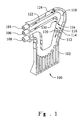
- an air separator is provided in a aspiration flow measurement device 100 for use in ophthalmic surgical systems.
- the aspiration flow measurement device 100 includes a housing 102 that may have an inlet 104 for receiving an aspirated fluid from a surgical site (not shown), an outlet 106 for output of air separated from the aspirated fluid, and an outlet 108 for output of the aspirated fluid to a collection reservoir (not shown).
- the housing 102 has a diagonally-oriented flow channel 110, and a vertically-oriented flow channel 130 that adjoins the diagonally-oriented flow channel at a junction 116.
- the diagonally-oriented flow channel 110 has a downstream portion 112 disposed downstream of the junction 116.
- the diagonally-oriented flow channel 110 also has an upstream portion 118 disposed upstream of the junction 116, which is in communication with an inlet flow channel 122.
- the inlet flow channel 122 (and the inlet to the upstream portion 118) has a cross-sectional area 124 of a size that is sufficient to permit or establish a fluid flow velocity V f of, for example, between 100 and 130 millimeters per second therethrough.
- the downstream portion 112 of the diagonally-oriented flow channel 110 has a cross-sectional area 114 that is greater than that of the upstream cross-sectional area 124.
- the downstream portion's cross-sectional area 114 is greater than the upstream cross-sectional area 124 by an amount or percentage that is sufficient to slow fluid flow through the diagonally-oriented flow channel 110 so as to cause air within the fluid to rise along the diagonally-oriented surface 120 and enter into the vertically-oriented flow channel 130.
- diagonally-oriented flow channel 110 could also be vertically-oriented. Therefore, the use of the term "diagonally-oriented” should also be understood to include vertically-oriented.
- the downstream cross-sectional area 114 is greater by an amount or percentage that is effective to increase resistance to flow and reduce the velocity of flow in the downstream portion to an extent that the buoyancy of any air causes the air to rise at a velocity faster than the velocity of the fluid flowing through the downstream portion.
- the downstream cross-sectional area 114 is greater than the upstream cross-sectional area 124 by an amount or percentage that will reduce the flow velocity of fluid in the downstream portion 112 to a velocity that is about the same as or less than the velocity of air bubbles rising due to buoyancy in the downstream portion 112.
- the upstream cross-sectional area 124 is not disposed immediately preceding the junction 116, but rather is positioned at a distance upstream of the junction 116, as shown in FIG. 1 .
- the upstream cross-sectional area 124 may be disposed closer to the junction 116. More specifically, the upstream cross-sectional area 124 is preferably within a predetermined distance of the junction 116, such that fluid flow velocity through the upstream cross-sectional area 124 is subsequently slowed to a separation velocity V s at a point downstream of the junction 116 between the diagonally-oriented flow channel 110 and the vertically-oriented flow channel 130.
- the upstream portion 118 may vary in cross-section to provide a gradual transition between the upstream cross-sectional area 124 and the downstream cross-sectional area 114.
- the transition from the upstream cross-sectional area 124 likewise is within a predetermined distance of the junction 116, to thereby ensure that that air within the fluid will have passed downstream of the junction 116 before rising upward towards the vertically-oriented flow channel 130.
- the upstream cross-sectional area 124 shown in FIG. 1 is disposed a distance upstream of the junction 116, the upstream cross-sectional area 124 may be positioned closer to the junction 116, as in the second embodiment of an air separator shown in FIG. 2 .
- a second embodiment of an air separator within a flow measurement device for use in ophthalmic surgical systems is provided with an inlet 204 and outlets 206 and 208, similar to inlet 104 and outlets 106 and 108 of Fig. 1 .
- the flow measurement device includes a housing 202 that includes a diagonally-oriented flow channel 210 and a vertically-oriented flow channel 230 that adjoins the diagonally-oriented flow channel at a junction 216.
- the diagonally-oriented flow channel 210 has an upstream portion 218 disposed upstream of the junction 216, and a downstream portion 212 disposed downstream of the junction 216.
- the diagonally-oriented flow channel 210 also has an upstream portion 218 that is in communication with an inlet flow channel.
- the upstream portion 218 includes an upstream cross-sectional area 224 of a size that is sufficient to permit or establish a fluid flow velocity V f of, for example, between 100 and 130 millimeters per second therethrough.
- the downstream portion 212 has a cross-sectional area 214 that is greater than that of the upstream cross-sectional area 224.
- the upstream cross-sectional area 224 is disposed immediately upstream of the junction 216, as shown in FIG. 2 .
- the upstream cross-sectional area 224 and the transition region are disposed within a predetermined distance of the junction 216 of the vertically-oriented flow channel 230.
- the downstream portion's cross-sectional area 214 is greater than that of the upstream cross-sectional area 224 by an amount that is sufficient to slow fluid flow through the first flow channel 210 as it passes the junction 216 so as to allow air within the fluid flow to rise along the first diagonally extending surface 220 and into the generally vertical flow channel 230.
- the upstream cross-sectional area 224 is preferably within a predetermined distance of the junction 216, such that fluid flow velocity through the upstream cross-sectional area 224 is subsequently slowed to a separation velocity V s at point downstream of the junction 216 between the diagonally-oriented flow channel 210 and the vertically-oriented flow channel 230. This predetermined distance ensures that air bubbles 228 within the fluid will begin rising (or establish a velocity in an upward direction) after passing downstream of the junction 216, such that the air bubbles 228 will rise upward into the vertically-oriented flow channel 230.
- the housing 202 further includes an electrode chamber for measuring aspiration fluid flow rate.
- the fluid measurement means preferably utilizes an isolated Hall-effect electromagnetic flow meter (not shown, but described in U.S. Patents 6,599,277 and 6,634,237 ), which takes advantage of the fact that the saline solution commonly used in ophthalmic surgery is electrically conductive.
- the Hall-effect involves the development of a voltage potential across conductive fluids flowing between current-carrying conductors, when subjected to a magnetic field. Thus, a voltage can be induced across an aspiration collection reservoir if a magnetic field is applied.
- Such flow measurement in an ophthalmic surgical pump system includes the application of a magnetic field source or electromagnetic magnet.
- the flow sensing electrode chamber further includes first and second electrode terminals disposed on generally opposite sides of the electrode terminal chamber.
- the fluid flowing through the electrode terminal chamber generally comprises an electrically conductive saline solution.
- the first and second electrode terminals are arranged opposite one another in a spaced-apart relationship that is sufficient to generate at least one electrical signal indicative of the flow rate of the fluid flowing through the electrode terminal chamber.
- the flow channels 210 and 230 are configured to separate air from the stream of fluid flow prior to fluid flow reaching flow sensing electrode chamber, to thereby allow a measurement of fluid flow without interference from noise inducing air bubbles.
- a similar arrangement is also embodied in the device of FIG. 1 .
- the second vertically-oriented flow channel preferably has a narrow cross-sectional area that is less than a predetermined percentage of the upstream cross-sectional area, below which percentage the narrow cross-sectional area is effective to substantially allow air flow and to substantially restrict liquid flow through the second vertically-oriented flow channel.
- the narrow cross-sectional area of the second vertically-oriented flow channel 230 is less than 50 percent of the upstream cross-sectional area 224 of the first flow channel 210.
- the downstream cross-sectional area 214 is preferably that is at least 50% greater than the upstream cross-sectional area 224.
- this channel is at an angle relative to the vertically-oriented flow channel, which angle is between about 10 degrees and about 80 degrees.
- the present invention provides an improvement to aspiration flow control, in configuring first and second flow channels to separate air bubbles from the stream of fluid flow to thereby restrict the passage of air bubbles to an aspiration flow measurement means.
- the present invention is illustrated herein by example, and various modifications may be made by a person of ordinary skill in the art.
Landscapes
- Health & Medical Sciences (AREA)
- Heart & Thoracic Surgery (AREA)
- Vascular Medicine (AREA)
- Engineering & Computer Science (AREA)
- Anesthesiology (AREA)
- Biomedical Technology (AREA)
- Hematology (AREA)
- Life Sciences & Earth Sciences (AREA)
- Animal Behavior & Ethology (AREA)
- General Health & Medical Sciences (AREA)
- Public Health (AREA)
- Veterinary Medicine (AREA)
- External Artificial Organs (AREA)
- Infusion, Injection, And Reservoir Apparatuses (AREA)
Claims (7)
- Aspirationsdurchfluss-Messvorrichtung für ein ophthalmisches mikrochirurgisches System, die aufweist:ein Gehäuse (102, 202) mit einem diagonal orientierten Durchflusskanal (110, 210) und einem vertikal orientierten Durchflusskanal (130, 230), der an den diagonal orientierten Durchflusskanal an einem Übergang (116, 216) angrenzt, wobei der diagonal orientierte Durchflusskanal eine Stromaufwärtsquerschnittfläche (124, 224), die stromaufwärts vom Übergang angeordnet ist, und einen Stromabwärtsabschnitt (112, 212) hat, der stromabwärts vom Übergang angeordnet ist, wobei der Stromabwärtsabschnitt eine Querschnittfläche (114, 214) hat, die um einen vorbestimmten Prozentsatz größer als die einer Stromaufwärtsquerschnittfläche (124, 224) ist, der ausreicht zu bewirken, dass sich die Geschwindigkeit von Fluid verlangsamt, das in den Stromabwärtsabschnitt (112, 212) eintritt, so dass Luft im Stromabwärtsabschnitt im Durchflusskanal aufsteigt und in den vertikal orientierten Durchflusskanal (130, 230) entweicht.
- Aspirationsdurchfluss-Messvorrichtung nach Anspruch 1, wobei der Stromabwärtsabschnitt (112, 212) eine Querschnittfläche (114, 214) hat, die um einen Prozentsatz größer als die der Stromaufwärtsquerschnittfläche (124, 224) ist, der ausreicht, eine ausreichende Erhöhung des Durchflusswiderstands zu erzeugen, um zu bewirken, dass Luftblasen aufsteigen und durch den vertikal orientierten Durchflusskanal (130, 230) entweichen, um dadurch den Durchgang von Flüssigkeit zu ermöglichen und den Durchgang von Luftblasen durch die Aspirationsdurchfluss-Messvorrichtung einzuschränken.
- Aspirationsdurchfluss-Messvorrichtung nach Anspruch 2, wobei die Querschnittfläche (114, 214) des Stromabwärtsabschnitts (112, 212) des diagonal orientierten Durchflusskanals (110, 210) mindestens 50% größer als die Stromaufwärtsquerschnittfläche (124, 224) ist.
- Aspirationsdurchfluss-Messvorrichtung nach Anspruch 1, wobei der vertikal orientierte Durchflusskanal (130, 230) eine schmale Querschnittfläche hat, die kleiner als ein vorbestimmter Prozentsatz der Stromaufwärtsquerschnittfläche (124, 224) des diagonal orientierten Durchflusskanals (110, 210) ist, wobei unter diesem Prozentsatz die schmale Querschnittfläche so wirkt, dass sie Luftdurchfluss im Wesentlichen ermöglicht und Flüssigkeitsdurchfluss durch den vertikal orientierten Durchflusskanal (130, 230) im Wesentlichen einschränkt.
- Aspirationsdurchfluss-Messvorrichtung nach Anspruch 1, wobei die schmale Querschnittfläche des vertikal orientierten Durchflusskanals (130, 230) weniger als 50 Prozent der Stromaufwärtsquerschnittfläche (124, 224) des diagonal orientierten Durchflusskanals (110, 210) beträgt.
- Aspirationsdurchfluss-Messvorrichtung nach Anspruch 1, wobei der diagonal orientierte Durchflusskanal (110, 210) in einem Winkel relativ zum vertikal orientierten Durchflusskanal (130, 230) liegt, wobei der Winkel zwischen etwa 10 Grad und etwa 80 Grad liegt.
- Aspirationsdurchfluss-Messvornchtung nach Anspruch 1, wobei das Ende des Stromaufwärtsabschnitts (118, 218) mit einer Stromaufwärtsquerschnittfläche (124, 224) in einem vorbestimmten Abstand des Übergangs (116, 216) zwischen dem diagonal orientierten Durchflusskanal (110, 210) und dem vertikal orientierten Durchflusskanal (130, 230) positioniert ist, so dass Fluiddurchfluss über den Übergang (116, 216) hinaus auf eine Trenngeschwindigkeit verlangsamt wird, die langsamer als die Geschwindigkeit von Luftblasen ist, die im Stromabwärtsabschnitt (112, 212) aufsteigen.
Applications Claiming Priority (2)
| Application Number | Priority Date | Filing Date | Title |
|---|---|---|---|
| US11/955,638 US7712360B2 (en) | 2007-12-13 | 2007-12-13 | Air separator for ophthalmic surgical system |
| PCT/US2008/085246 WO2009076098A2 (en) | 2007-12-13 | 2008-12-02 | Air separator for ophthalmic surgical system |
Publications (2)
| Publication Number | Publication Date |
|---|---|
| EP2222352A2 EP2222352A2 (de) | 2010-09-01 |
| EP2222352B1 true EP2222352B1 (de) | 2014-06-18 |
Family
ID=40754213
Family Applications (1)
| Application Number | Title | Priority Date | Filing Date |
|---|---|---|---|
| EP08860301.4A Not-in-force EP2222352B1 (de) | 2007-12-13 | 2008-12-02 | Luftseparator für ein ophthalmisches operationssystem |
Country Status (9)
| Country | Link |
|---|---|
| US (1) | US7712360B2 (de) |
| EP (1) | EP2222352B1 (de) |
| JP (1) | JP5357177B2 (de) |
| KR (1) | KR101528949B1 (de) |
| CN (1) | CN101896212B (de) |
| BR (1) | BRPI0819913A2 (de) |
| CA (1) | CA2708305C (de) |
| ES (1) | ES2476608T3 (de) |
| WO (1) | WO2009076098A2 (de) |
Families Citing this family (3)
| Publication number | Priority date | Publication date | Assignee | Title |
|---|---|---|---|---|
| USD694404S1 (en) * | 2011-06-09 | 2013-11-26 | Medline Industries, Inc. | Fluid collection container lid |
| USD733867S1 (en) * | 2012-03-17 | 2015-07-07 | Abbott Medical Optics Inc. | Surgical cassette for a surgical system |
| US12005171B2 (en) * | 2020-05-28 | 2024-06-11 | Minnetronix Neuro, Inc. | Filtering systems and filtering manifolds for use with filtering systems |
Family Cites Families (26)
| Publication number | Priority date | Publication date | Assignee | Title |
|---|---|---|---|---|
| SE308036B (de) * | 1963-02-18 | 1969-01-27 | Lkb Produkter Ab | |
| US4295260A (en) | 1979-10-15 | 1981-10-20 | Divers Robert M | Tool for removing sleeves from cylinders |
| US4395260A (en) * | 1981-06-01 | 1983-07-26 | Sorenson Research Co., Inc. | Drip chamber |
| JPS59101512A (ja) * | 1982-12-03 | 1984-06-12 | Hitachi Ltd | 石炭ガス化複合発電プラント |
| US4688418A (en) * | 1985-10-17 | 1987-08-25 | Texaco Inc. | Method and apparatus for determining mass flow rate and quality in a steam line |
| US4760742A (en) * | 1987-04-10 | 1988-08-02 | Texaco Inc. | Multi-phase petroleum stream monitoring system and method |
| US5127272A (en) * | 1991-01-03 | 1992-07-07 | Texaco Ltd. | Multiphase flow rate monitoring means and method |
| DE4106995A1 (de) * | 1991-03-05 | 1992-09-24 | Durango Holding Gmbh | Verfahren und vorrichtung zur messung eines fluessigkeitsstromes |
| US5526684A (en) * | 1992-08-05 | 1996-06-18 | Chevron Research And Technology Company, A Division Of Chevron U.S.A. Inc. | Method and apparatus for measuring multiphase flows |
| US5390547A (en) * | 1993-11-16 | 1995-02-21 | Liu; Ke-Tien | Multiphase flow separation and measurement system |
| US5441482A (en) | 1994-05-11 | 1995-08-15 | The Regents Of The University Of Minnesota | Jet driven surgical suction device and method of using |
| DE19620591B4 (de) * | 1996-05-22 | 2004-08-26 | Fresenius Medical Care Deutschland Gmbh | Vorrichtung zum Entfernen von Gasen aus Flüssigkeiten |
| JPH1043293A (ja) * | 1996-08-08 | 1998-02-17 | Senko Ika Kogyo Kk | 液体中気泡除去装置 |
| GB2366220B (en) * | 2000-08-23 | 2003-03-19 | Schlumberger Holdings | Device for diverting fluid from a pipeline |
| JP2002282355A (ja) * | 2001-03-27 | 2002-10-02 | Nipro Corp | ドリップチャンバー |
| US6599277B2 (en) | 2001-11-30 | 2003-07-29 | Bausch & Lomb Incorporated | Aspiration flow meter and control |
| US6634237B2 (en) | 2001-11-30 | 2003-10-21 | Bausch & Lomb Incorporated | Collection reservoir for use with flow meter control system |
| US7469727B2 (en) * | 2002-08-21 | 2008-12-30 | Biodrain Medical, Inc. | Method and apparatus for disposing of liquid surgical waste for protection of healthcare workers |
| ITMO20030324A1 (it) | 2003-11-28 | 2005-05-29 | Aries S R L | Apparato medicale. |
| JP4500617B2 (ja) * | 2004-07-22 | 2010-07-14 | テルモ株式会社 | 気泡除去装置 |
| US7604615B2 (en) * | 2006-03-20 | 2009-10-20 | Alcon, Inc. | Surgical cassette with bubble separating structure |
| US8202243B2 (en) * | 2005-10-27 | 2012-06-19 | Novartis Ag | Fluid pressure sensing chamber |
| ATE505221T1 (de) * | 2006-03-20 | 2011-04-15 | Alcon Inc | Chirurgische kassette mit blasentrennstruktur |
| US7780633B2 (en) | 2006-03-20 | 2010-08-24 | Alcon, Inc. | Surgical cassette with bubble breaking structure |
| US8343100B2 (en) * | 2006-03-29 | 2013-01-01 | Novartis Ag | Surgical system having a non-invasive flow sensor |
| US8061216B2 (en) * | 2007-12-21 | 2011-11-22 | Bausch & Lomb Incorporated | Aspiration flow mesurement system with flow signal air bubble filter |
-
2007
- 2007-12-13 US US11/955,638 patent/US7712360B2/en active Active
-
2008
- 2008-12-02 CN CN2008801201570A patent/CN101896212B/zh not_active Expired - Fee Related
- 2008-12-02 KR KR1020107012886A patent/KR101528949B1/ko not_active Expired - Fee Related
- 2008-12-02 EP EP08860301.4A patent/EP2222352B1/de not_active Not-in-force
- 2008-12-02 CA CA2708305A patent/CA2708305C/en not_active Expired - Fee Related
- 2008-12-02 BR BRPI0819913-2A patent/BRPI0819913A2/pt not_active Application Discontinuation
- 2008-12-02 JP JP2010538045A patent/JP5357177B2/ja not_active Expired - Fee Related
- 2008-12-02 ES ES08860301.4T patent/ES2476608T3/es active Active
- 2008-12-02 WO PCT/US2008/085246 patent/WO2009076098A2/en not_active Ceased
Also Published As
| Publication number | Publication date |
|---|---|
| HK1146582A1 (en) | 2011-06-24 |
| US20090157018A1 (en) | 2009-06-18 |
| EP2222352A2 (de) | 2010-09-01 |
| WO2009076098A3 (en) | 2009-09-24 |
| KR20100098392A (ko) | 2010-09-06 |
| CA2708305A1 (en) | 2009-06-18 |
| JP2011505976A (ja) | 2011-03-03 |
| ES2476608T3 (es) | 2014-07-15 |
| WO2009076098A2 (en) | 2009-06-18 |
| US7712360B2 (en) | 2010-05-11 |
| CN101896212A (zh) | 2010-11-24 |
| JP5357177B2 (ja) | 2013-12-04 |
| CA2708305C (en) | 2012-02-07 |
| CN101896212B (zh) | 2012-11-28 |
| KR101528949B1 (ko) | 2015-06-15 |
| BRPI0819913A2 (pt) | 2015-09-01 |
Similar Documents
| Publication | Publication Date | Title |
|---|---|---|
| CN101896213B (zh) | 用于检测眼科手术系统中流量的内陷电极 | |
| DE60211374T2 (de) | Auffangbehälter zur Verwendung mit einem Flußmesser-Kontrollsystem | |
| EP2222352B1 (de) | Luftseparator für ein ophthalmisches operationssystem | |
| CA2050164C (en) | Particle detector and particle detecting apparatus having the detector | |
| JP2007503597A5 (de) | ||
| CN110868950B (zh) | 排烟电外科仪器 | |
| JP4025017B2 (ja) | 粒子検出システム | |
| DE60232508D1 (de) | Vorrichtung zum koaleszieren eines fluids | |
| HK1146582B (en) | Air separator for ophthalmic surgical system | |
| WO2018179647A1 (ja) | 流路ユニット及び微小粒子分析装置 | |
| US8303553B2 (en) | Flow limiter for a fluid flowing in an aspiration branch of a surgical system, and surgical system | |
| JP2005062137A (ja) | 液体中の微粒子計数装置 | |
| JP2018011947A (ja) | 混合用チャンバ | |
| US10912885B2 (en) | Device and method for infusing and aspirating fluid | |
| Kumar et al. | MEMS based flow cytometer with instrumentation system for detection of micro particles for health care applications | |
| HK1146583B (en) | Recessed electrodes for sensing flow in ophthalmic surgical system |
Legal Events
| Date | Code | Title | Description |
|---|---|---|---|
| PUAI | Public reference made under article 153(3) epc to a published international application that has entered the european phase |
Free format text: ORIGINAL CODE: 0009012 |
|
| 17P | Request for examination filed |
Effective date: 20100709 |
|
| AK | Designated contracting states |
Kind code of ref document: A2 Designated state(s): AT BE BG CH CY CZ DE DK EE ES FI FR GB GR HR HU IE IS IT LI LT LU LV MC MT NL NO PL PT RO SE SI SK TR |
|
| AX | Request for extension of the european patent |
Extension state: AL BA MK RS |
|
| DAX | Request for extension of the european patent (deleted) | ||
| REG | Reference to a national code |
Ref country code: HK Ref legal event code: DE Ref document number: 1146582 Country of ref document: HK |
|
| 17Q | First examination report despatched |
Effective date: 20120808 |
|
| GRAP | Despatch of communication of intention to grant a patent |
Free format text: ORIGINAL CODE: EPIDOSNIGR1 |
|
| INTG | Intention to grant announced |
Effective date: 20140113 |
|
| GRAS | Grant fee paid |
Free format text: ORIGINAL CODE: EPIDOSNIGR3 |
|
| GRAA | (expected) grant |
Free format text: ORIGINAL CODE: 0009210 |
|
| AK | Designated contracting states |
Kind code of ref document: B1 Designated state(s): AT BE BG CH CY CZ DE DK EE ES FI FR GB GR HR HU IE IS IT LI LT LU LV MC MT NL NO PL PT RO SE SI SK TR |
|
| REG | Reference to a national code |
Ref country code: GB Ref legal event code: FG4D |
|
| REG | Reference to a national code |
Ref country code: CH Ref legal event code: EP |
|
| REG | Reference to a national code |
Ref country code: ES Ref legal event code: FG2A Ref document number: 2476608 Country of ref document: ES Kind code of ref document: T3 Effective date: 20140715 Ref country code: AT Ref legal event code: REF Ref document number: 672966 Country of ref document: AT Kind code of ref document: T Effective date: 20140715 |
|
| REG | Reference to a national code |
Ref country code: IE Ref legal event code: FG4D |
|
| REG | Reference to a national code |
Ref country code: DE Ref legal event code: R096 Ref document number: 602008032904 Country of ref document: DE Effective date: 20140731 |
|
| REG | Reference to a national code |
Ref country code: HK Ref legal event code: GR Ref document number: 1146582 Country of ref document: HK |
|
| PG25 | Lapsed in a contracting state [announced via postgrant information from national office to epo] |
Ref country code: NO Free format text: LAPSE BECAUSE OF FAILURE TO SUBMIT A TRANSLATION OF THE DESCRIPTION OR TO PAY THE FEE WITHIN THE PRESCRIBED TIME-LIMIT Effective date: 20140918 Ref country code: CY Free format text: LAPSE BECAUSE OF FAILURE TO SUBMIT A TRANSLATION OF THE DESCRIPTION OR TO PAY THE FEE WITHIN THE PRESCRIBED TIME-LIMIT Effective date: 20140618 Ref country code: GR Free format text: LAPSE BECAUSE OF FAILURE TO SUBMIT A TRANSLATION OF THE DESCRIPTION OR TO PAY THE FEE WITHIN THE PRESCRIBED TIME-LIMIT Effective date: 20140919 Ref country code: LT Free format text: LAPSE BECAUSE OF FAILURE TO SUBMIT A TRANSLATION OF THE DESCRIPTION OR TO PAY THE FEE WITHIN THE PRESCRIBED TIME-LIMIT Effective date: 20140618 Ref country code: FI Free format text: LAPSE BECAUSE OF FAILURE TO SUBMIT A TRANSLATION OF THE DESCRIPTION OR TO PAY THE FEE WITHIN THE PRESCRIBED TIME-LIMIT Effective date: 20140618 |
|
| REG | Reference to a national code |
Ref country code: NL Ref legal event code: VDEP Effective date: 20140618 |
|
| REG | Reference to a national code |
Ref country code: AT Ref legal event code: MK05 Ref document number: 672966 Country of ref document: AT Kind code of ref document: T Effective date: 20140618 |
|
| REG | Reference to a national code |
Ref country code: LT Ref legal event code: MG4D |
|
| PG25 | Lapsed in a contracting state [announced via postgrant information from national office to epo] |
Ref country code: HR Free format text: LAPSE BECAUSE OF FAILURE TO SUBMIT A TRANSLATION OF THE DESCRIPTION OR TO PAY THE FEE WITHIN THE PRESCRIBED TIME-LIMIT Effective date: 20140618 Ref country code: LV Free format text: LAPSE BECAUSE OF FAILURE TO SUBMIT A TRANSLATION OF THE DESCRIPTION OR TO PAY THE FEE WITHIN THE PRESCRIBED TIME-LIMIT Effective date: 20140618 Ref country code: SE Free format text: LAPSE BECAUSE OF FAILURE TO SUBMIT A TRANSLATION OF THE DESCRIPTION OR TO PAY THE FEE WITHIN THE PRESCRIBED TIME-LIMIT Effective date: 20140618 |
|
| PG25 | Lapsed in a contracting state [announced via postgrant information from national office to epo] |
Ref country code: SK Free format text: LAPSE BECAUSE OF FAILURE TO SUBMIT A TRANSLATION OF THE DESCRIPTION OR TO PAY THE FEE WITHIN THE PRESCRIBED TIME-LIMIT Effective date: 20140618 Ref country code: CZ Free format text: LAPSE BECAUSE OF FAILURE TO SUBMIT A TRANSLATION OF THE DESCRIPTION OR TO PAY THE FEE WITHIN THE PRESCRIBED TIME-LIMIT Effective date: 20140618 Ref country code: EE Free format text: LAPSE BECAUSE OF FAILURE TO SUBMIT A TRANSLATION OF THE DESCRIPTION OR TO PAY THE FEE WITHIN THE PRESCRIBED TIME-LIMIT Effective date: 20140618 Ref country code: PT Free format text: LAPSE BECAUSE OF FAILURE TO SUBMIT A TRANSLATION OF THE DESCRIPTION OR TO PAY THE FEE WITHIN THE PRESCRIBED TIME-LIMIT Effective date: 20141020 Ref country code: RO Free format text: LAPSE BECAUSE OF FAILURE TO SUBMIT A TRANSLATION OF THE DESCRIPTION OR TO PAY THE FEE WITHIN THE PRESCRIBED TIME-LIMIT Effective date: 20140618 |
|
| PG25 | Lapsed in a contracting state [announced via postgrant information from national office to epo] |
Ref country code: IS Free format text: LAPSE BECAUSE OF FAILURE TO SUBMIT A TRANSLATION OF THE DESCRIPTION OR TO PAY THE FEE WITHIN THE PRESCRIBED TIME-LIMIT Effective date: 20141018 Ref country code: PL Free format text: LAPSE BECAUSE OF FAILURE TO SUBMIT A TRANSLATION OF THE DESCRIPTION OR TO PAY THE FEE WITHIN THE PRESCRIBED TIME-LIMIT Effective date: 20140618 Ref country code: AT Free format text: LAPSE BECAUSE OF FAILURE TO SUBMIT A TRANSLATION OF THE DESCRIPTION OR TO PAY THE FEE WITHIN THE PRESCRIBED TIME-LIMIT Effective date: 20140618 Ref country code: NL Free format text: LAPSE BECAUSE OF FAILURE TO SUBMIT A TRANSLATION OF THE DESCRIPTION OR TO PAY THE FEE WITHIN THE PRESCRIBED TIME-LIMIT Effective date: 20140618 |
|
| REG | Reference to a national code |
Ref country code: DE Ref legal event code: R097 Ref document number: 602008032904 Country of ref document: DE |
|
| PLBE | No opposition filed within time limit |
Free format text: ORIGINAL CODE: 0009261 |
|
| STAA | Information on the status of an ep patent application or granted ep patent |
Free format text: STATUS: NO OPPOSITION FILED WITHIN TIME LIMIT |
|
| PG25 | Lapsed in a contracting state [announced via postgrant information from national office to epo] |
Ref country code: DK Free format text: LAPSE BECAUSE OF FAILURE TO SUBMIT A TRANSLATION OF THE DESCRIPTION OR TO PAY THE FEE WITHIN THE PRESCRIBED TIME-LIMIT Effective date: 20140618 |
|
| 26N | No opposition filed |
Effective date: 20150319 |
|
| PG25 | Lapsed in a contracting state [announced via postgrant information from national office to epo] |
Ref country code: BE Free format text: LAPSE BECAUSE OF FAILURE TO SUBMIT A TRANSLATION OF THE DESCRIPTION OR TO PAY THE FEE WITHIN THE PRESCRIBED TIME-LIMIT Effective date: 20140618 |
|
| PG25 | Lapsed in a contracting state [announced via postgrant information from national office to epo] |
Ref country code: SI Free format text: LAPSE BECAUSE OF FAILURE TO SUBMIT A TRANSLATION OF THE DESCRIPTION OR TO PAY THE FEE WITHIN THE PRESCRIBED TIME-LIMIT Effective date: 20140618 Ref country code: LU Free format text: LAPSE BECAUSE OF FAILURE TO SUBMIT A TRANSLATION OF THE DESCRIPTION OR TO PAY THE FEE WITHIN THE PRESCRIBED TIME-LIMIT Effective date: 20141202 |
|
| REG | Reference to a national code |
Ref country code: CH Ref legal event code: PL |
|
| REG | Reference to a national code |
Ref country code: IE Ref legal event code: MM4A |
|
| PG25 | Lapsed in a contracting state [announced via postgrant information from national office to epo] |
Ref country code: IE Free format text: LAPSE BECAUSE OF NON-PAYMENT OF DUE FEES Effective date: 20141202 Ref country code: CH Free format text: LAPSE BECAUSE OF NON-PAYMENT OF DUE FEES Effective date: 20141231 Ref country code: LI Free format text: LAPSE BECAUSE OF NON-PAYMENT OF DUE FEES Effective date: 20141231 |
|
| REG | Reference to a national code |
Ref country code: FR Ref legal event code: PLFP Year of fee payment: 8 |
|
| PG25 | Lapsed in a contracting state [announced via postgrant information from national office to epo] |
Ref country code: BG Free format text: LAPSE BECAUSE OF FAILURE TO SUBMIT A TRANSLATION OF THE DESCRIPTION OR TO PAY THE FEE WITHIN THE PRESCRIBED TIME-LIMIT Effective date: 20140618 Ref country code: MC Free format text: LAPSE BECAUSE OF FAILURE TO SUBMIT A TRANSLATION OF THE DESCRIPTION OR TO PAY THE FEE WITHIN THE PRESCRIBED TIME-LIMIT Effective date: 20140618 |
|
| PG25 | Lapsed in a contracting state [announced via postgrant information from national office to epo] |
Ref country code: HU Free format text: LAPSE BECAUSE OF FAILURE TO SUBMIT A TRANSLATION OF THE DESCRIPTION OR TO PAY THE FEE WITHIN THE PRESCRIBED TIME-LIMIT; INVALID AB INITIO Effective date: 20081202 Ref country code: MT Free format text: LAPSE BECAUSE OF FAILURE TO SUBMIT A TRANSLATION OF THE DESCRIPTION OR TO PAY THE FEE WITHIN THE PRESCRIBED TIME-LIMIT Effective date: 20140618 Ref country code: TR Free format text: LAPSE BECAUSE OF FAILURE TO SUBMIT A TRANSLATION OF THE DESCRIPTION OR TO PAY THE FEE WITHIN THE PRESCRIBED TIME-LIMIT Effective date: 20140618 |
|
| REG | Reference to a national code |
Ref country code: FR Ref legal event code: PLFP Year of fee payment: 9 |
|
| REG | Reference to a national code |
Ref country code: FR Ref legal event code: PLFP Year of fee payment: 10 |
|
| PGFP | Annual fee paid to national office [announced via postgrant information from national office to epo] |
Ref country code: FR Payment date: 20171120 Year of fee payment: 10 |
|
| PGFP | Annual fee paid to national office [announced via postgrant information from national office to epo] |
Ref country code: GB Payment date: 20171128 Year of fee payment: 10 Ref country code: IT Payment date: 20171219 Year of fee payment: 10 |
|
| PGFP | Annual fee paid to national office [announced via postgrant information from national office to epo] |
Ref country code: ES Payment date: 20180105 Year of fee payment: 10 Ref country code: DE Payment date: 20171221 Year of fee payment: 10 |
|
| REG | Reference to a national code |
Ref country code: DE Ref legal event code: R119 Ref document number: 602008032904 Country of ref document: DE |
|
| GBPC | Gb: european patent ceased through non-payment of renewal fee |
Effective date: 20181202 |
|
| PG25 | Lapsed in a contracting state [announced via postgrant information from national office to epo] |
Ref country code: IT Free format text: LAPSE BECAUSE OF NON-PAYMENT OF DUE FEES Effective date: 20181202 Ref country code: FR Free format text: LAPSE BECAUSE OF NON-PAYMENT OF DUE FEES Effective date: 20181231 Ref country code: DE Free format text: LAPSE BECAUSE OF NON-PAYMENT OF DUE FEES Effective date: 20190702 |
|
| PG25 | Lapsed in a contracting state [announced via postgrant information from national office to epo] |
Ref country code: GB Free format text: LAPSE BECAUSE OF NON-PAYMENT OF DUE FEES Effective date: 20181202 |
|
| REG | Reference to a national code |
Ref country code: ES Ref legal event code: FD2A Effective date: 20200131 |
|
| PG25 | Lapsed in a contracting state [announced via postgrant information from national office to epo] |
Ref country code: ES Free format text: LAPSE BECAUSE OF NON-PAYMENT OF DUE FEES Effective date: 20181203 |