EP2221965A2 - Verstärker mit verschachtelten Signalen zur Unterdrückung der PWM-Schwankung - Google Patents
Verstärker mit verschachtelten Signalen zur Unterdrückung der PWM-Schwankung Download PDFInfo
- Publication number
- EP2221965A2 EP2221965A2 EP20100164465 EP10164465A EP2221965A2 EP 2221965 A2 EP2221965 A2 EP 2221965A2 EP 20100164465 EP20100164465 EP 20100164465 EP 10164465 A EP10164465 A EP 10164465A EP 2221965 A2 EP2221965 A2 EP 2221965A2
- Authority
- EP
- European Patent Office
- Prior art keywords
- signal
- amplifier
- interleaved
- feedback
- generate
- Prior art date
- Legal status (The legal status is an assumption and is not a legal conclusion. Google has not performed a legal analysis and makes no representation as to the accuracy of the status listed.)
- Granted
Links
- 230000001629 suppression Effects 0.000 title description 7
- 239000013598 vector Substances 0.000 claims abstract description 45
- 230000004044 response Effects 0.000 claims abstract description 25
- 238000012546 transfer Methods 0.000 claims description 56
- 238000000034 method Methods 0.000 claims description 24
- 230000003111 delayed effect Effects 0.000 claims description 13
- 238000012937 correction Methods 0.000 claims description 10
- 230000002238 attenuated effect Effects 0.000 claims description 8
- 238000001914 filtration Methods 0.000 description 10
- 238000001228 spectrum Methods 0.000 description 9
- 238000010586 diagram Methods 0.000 description 8
- 230000003321 amplification Effects 0.000 description 7
- 238000003199 nucleic acid amplification method Methods 0.000 description 7
- 230000008569 process Effects 0.000 description 7
- 230000008859 change Effects 0.000 description 5
- 238000012545 processing Methods 0.000 description 5
- 230000009467 reduction Effects 0.000 description 4
- 230000005236 sound signal Effects 0.000 description 4
- 238000004458 analytical method Methods 0.000 description 3
- 230000003595 spectral effect Effects 0.000 description 3
- 239000010752 BS 2869 Class D Substances 0.000 description 2
- 238000013459 approach Methods 0.000 description 2
- 239000003990 capacitor Substances 0.000 description 2
- 238000006243 chemical reaction Methods 0.000 description 2
- 230000001934 delay Effects 0.000 description 2
- 230000000694 effects Effects 0.000 description 2
- 230000006872 improvement Effects 0.000 description 2
- 239000000758 substrate Substances 0.000 description 2
- 230000007704 transition Effects 0.000 description 2
- 230000009118 appropriate response Effects 0.000 description 1
- 238000009795 derivation Methods 0.000 description 1
- 238000013461 design Methods 0.000 description 1
- 238000010790 dilution Methods 0.000 description 1
- 239000012895 dilution Substances 0.000 description 1
- 238000005516 engineering process Methods 0.000 description 1
- 230000002708 enhancing effect Effects 0.000 description 1
- 230000010354 integration Effects 0.000 description 1
- 230000007246 mechanism Effects 0.000 description 1
- 229920006395 saturated elastomer Polymers 0.000 description 1
- 238000006467 substitution reaction Methods 0.000 description 1
Images


Classifications
-
- H—ELECTRICITY
- H03—ELECTRONIC CIRCUITRY
- H03F—AMPLIFIERS
- H03F3/00—Amplifiers with only discharge tubes or only semiconductor devices as amplifying elements
- H03F3/20—Power amplifiers, e.g. Class B amplifiers, Class C amplifiers
- H03F3/21—Power amplifiers, e.g. Class B amplifiers, Class C amplifiers with semiconductor devices only
- H03F3/217—Class D power amplifiers; Switching amplifiers
- H03F3/2173—Class D power amplifiers; Switching amplifiers of the bridge type
-
- H—ELECTRICITY
- H03—ELECTRONIC CIRCUITRY
- H03F—AMPLIFIERS
- H03F1/00—Details of amplifiers with only discharge tubes, only semiconductor devices or only unspecified devices as amplifying elements
- H03F1/32—Modifications of amplifiers to reduce non-linear distortion
-
- H—ELECTRICITY
- H03—ELECTRONIC CIRCUITRY
- H03K—PULSE TECHNIQUE
- H03K7/00—Modulating pulses with a continuously-variable modulating signal
- H03K7/08—Duration or width modulation ; Duty cycle modulation
-
- H—ELECTRICITY
- H03—ELECTRONIC CIRCUITRY
- H03K—PULSE TECHNIQUE
- H03K17/00—Electronic switching or gating, i.e. not by contact-making and –breaking
- H03K17/16—Modifications for eliminating interference voltages or currents
-
- H—ELECTRICITY
- H03—ELECTRONIC CIRCUITRY
- H03K—PULSE TECHNIQUE
- H03K2217/00—Indexing scheme related to electronic switching or gating, i.e. not by contact-making or -breaking covered by H03K17/00
- H03K2217/0036—Means reducing energy consumption
Definitions
- the invention generally relates to amplifiers and, more particularly, to an interleaved amplifier employing interleaved signals for PWM ripple suppression.
- Pulse width modulation (PWM) amplification for audio applications has been used to increase efficiency by incorporating output devices that act as switches as opposed to linear devices that must dissipate a substantial amount of power.
- PWM amplifiers an audio input signal is converted to a pulse width modulated waveform.
- an audio signal is provided to the amplifier to modulate the width of an ultrasonic rectangular waveform based, for example, on the amplitude of the audio signal.
- the modulated waveform is used to drive one or more output devices as switches that are either fully saturated or off.
- the output devices often implemented using switching power transistors, may be aligned in half-bridge pairs such that one device of the pair switches a positive voltage to the output, while the other device switches a negative voltage to the output.
- the switched output signals may be provided to the input of a low-pass filter in an attempt to remove harmonic signals and sidebands that are beyond the spectrum of the desired output waveform.
- the filtered analog signal is used to drive the load, such as a loudspeaker.
- class-D amplifiers One set of pulse width modulated amplifier architectures, known as class-D amplifiers, are theoretically 100% efficient because the output transistors are either completely on, or completely off. These amplifiers, however, may be problematic since the timing of the switching of the transistors must be precisely controlled.
- the switches operate in time alternation. Ideally, the switching is perfectly timed so that one transistor instantaneously turns off as the other instantaneously turns on. If the switching is not perfectly timed, both the positive and negative switching devices may be on at the same time, allowing high "shoot-through" current, which may destroy the circuitry of a subsequent stage in the amplifier system. Therefore, in practice, a delay may be purposely introduced between the time at which one transistor turns off and the other transistor turns on. The time between the conduction intervals of the two switches when neither switch is on is known as deadtime. Deadtime may result in distortion and, therefore, should be minimized. Conversely, an insufficient amount of that time may result in undesired shoot-through current.
- the amplifier architectures used in certain of the Crown Audio amplifiers are known by various names including opposed current amplifiers, a balanced current amplifiers (BCA ® ), and "I-class" amplifiers.
- BCA ® balanced current amplifiers
- I-class amplifiers.
- the positive and negative switching pulses corresponding to the modulated waveform are time interleaved with one another.
- the interleaved pulses turn the switches on and off in an overlapping manner at a 50% duty cycle.
- the positive and negative power sources through-connected by the switches cancel each other out to provide a null output signal.
- the duty cycle of the interleaved pulses are such that the duty cycle of the switch through-connecting the positive power source increases.
- the incoming signal falls below the zero-crossing and goes to a negative state, the converse occurs.
- the opposed current amplifier architecture provides a significant improvement over conventional PWM amplifiers
- the architecture may be the subject of improvements.
- the distortion results of an amplification system using multiple opposed current amplifiers that are interleaved with one another may be improved through the use of intelligently designed feedback systems.
- the amplifier includes an interleaved PWM amplifier that generates interleaved PWM pulses in response to a modified input signal and one or more carrier signals.
- the interleaved PWM pulses of the amplifier are used to drive a power stage, such as an opposed current power stage.
- the amplifier also includes an interleaved PWM generator that provides interleaved PWM pulses in response to the modified input signal and one or more further carrier signals.
- the carrier signals used by the PWM generator may differ in phase from the carrier signals used by the interleaved PWM amplifier to generate its interleaved PWM pulses.
- One or more feedback circuits are employed in the generation of the modified input signal. More particularly, the feedback circuit(s) generates the modified input signal based on an input signal that is to be amplified and the interleaved PWM pulses of the interleaved PWM generator.
- a first feedback circuit may be implemented to feedback an output of the power stage of the interleaved amplifier to generate a first feedback signal
- a second feedback circuit may be implemented to feedback the interleaved PWM pulses of the PWM generator to generate a second feedback signal.
- a combiner circuit may be used to combine the input signal, the first feedback signal, and the second feedback signal to generate the modified input signal.
- the signal transfer characteristics of various amplifier sections may be manipulated to meet the desired degree of distortion reduction.
- the interleaved PWM amplifier and the first feedback circuit may combine to exhibit a first signal transfer characteristic
- the interleaved PWM generator and the second feedback circuit may combine to exhibit a second signal transfer characteristic.
- the first and second transfer characteristics may be selected so that they are proportional to one another in about the same ratio as N L to N N over at least a predetermined portion of an output bandwidth of the amplifier, where N L is the interleave order of the interleaved PWM generator and N N is the interleave order of the interleaved PWM amplifier.
- the interleaved PWM amplifier may have an interleave order of one (non-interleaved).
- Figure 1 is a schematic block diagram of one example of an interleaved amplifier that may be used to implement the amplifier systems shown in Figures 3 through 5 .
- Figure 3 is a block diagram of one example of an amplifier employing an interleaved PWM feedback signal that is generated from a carrier that differs in phase from the carrier used to generate the PWM drive signals provided to the power stage of the amplifier.
- Figure 4 is a block diagram of a further example of an amplifier system employing an interleaved PWM feedback signal that is generated from a carrier that differs in phase from the carrier used to generate the PWM drive signals provided to the power stage of the amplifier.
- Figure 5 is a block diagram of a still further example of an amplifier system employing an interleaved PWM feedback signal that is generated from a carrier that differs in phase from the carrier used to generate the PWM drive signals provided to the power stage of the amplifier.
- Figure 6 is a block diagram of a still further example of an amplifier system employing an interleaved PWM feedback signal, where the desired characteristics of the feedback signal may be determined by the characteristics of an attenuator circuit and a delay circuit.
- Figure 7 illustrates a number of interrelated operations that may be used to implement one or more of the amplifier systems shown in Figures 3 through 6 .
- Figure 8 illustrates a number of interrelated operations that may be used to implement one or more of the amplifier systems shown in Figures 3 through 6 , where the output signal of the amplifier power stage is used in addition to the interleaved PWM feedback signal to generate the modified input signal to the interleaved PWM amplifier.
- Figure 9 is a block diagram of a further amplifier system that employs interleaved PWM signals for PWM ripple suppression.
- Figure 10 illustrates a number of interrelated operations that may be used to implement the amplifier system shown in Figure 9 .
- 0 ⁇ M 1.0 ⁇ s is the signal frequency in radians/second ⁇ c is the PWM carrier/switching frequency in radians/second
- V o the peak output voltage of the PWM waveform
- m is the integer harmonic order number of the carrier band 1 ⁇ m ⁇ ⁇ n is the
- the leading cosine term is the intended signal for a process whose input is a cosine of radian frequency ⁇ s and whose amplitude relative to the modulating triangular waveform is of proportion M .
- the second part of (Equation 1) is composed of harmonics ( m ) of the modulating triangle and sideband pairs ( ⁇ n ) about each harmonic.
- that signal passband may be less than or equal to about 20 KHz, but may often be as high as 40 KHz in high end audio systems. Signals that lie outside the frequency passband may be measured and used as an indicator of amplifier performance.
- An exemplary opposed current amplifier that may be used to implement an interleaved amplifier system is shown generally at 100 of Figure 1 .
- the illustrated system includes a pulse width modulator section 105 and an opposed current drive section 110.
- the pulse width modulator section 105 includes an input section 113 including an error amplifier 115.
- Error amplifier 115 receives the audio signal that is to be amplified Vin as well as a feedback signal Vfb.
- the feedback signal Vfb is subtracted from the audio signal Vin by the error amplifier 115 to generate a modified input signal +Vmod at its output.
- This output is provided to the input of an inverter circuit 120, which generates an output signal -Vmod that is approximately 180 degrees out of phase with +Vmod.
- Signals +Vmod and -Vmod are provided to the input of a positive pulse modulator circuit 130 and negative pulse modulator circuit 125, respectively. Both modulator circuits 130 and 125 modulate their respective input signals +Vmod and -Vmod with a carrier signal that is provided at one or more lines 135 by a carrier generator 140.
- the carrier signal may be implemented as an ultrasonic frequency triangle wave. It also may be possible to use other carrier signal types, depending on the particular application.
- the output of positive pulse modulator 130 is provided as an input to the opposed current drive section 110 to control the state of switch device 160.
- switch device 160 is used to through-connect a positive voltage +Vcc to a load through a low-pass filter when in the conductive state.
- the low-pass filter in this example is comprised of inductor 165 and capacitor 155.
- the output of negative pulse modulator 125 is provided as an input to the opposed current drive section 110 to control the state of switch device 145.
- switch device 145 is used to through-connect a negative voltage -Vcc to the load through a further low-pass filter when in the conductive state.
- the further low-pass filter in this example is comprised of inductor 150 and capacitor 155.
- Inductors 150 and 165 may both have the same inductance value and characteristics.
- Switch devices 145 and 160 may be implemented, for example, using one or more of a variety of different switching transistor technologies.
- Diodes 170 and 175 function as freewheel diodes during the switching operations.
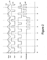
- Figure 2 illustrates the relationship between different waveforms that are generated in the opposed current amplifier shown in Figure 1 .
- a single triangular carrier waveform 205 (Vcar) is shown centered at 0V, and the modified input signal +Vmod is shown as a dotted line at 210.
- the pulse signals provided to the switches 160, 145 are illustrated by waveforms 215 and 220, respectively.
- Pulse signals 215 and 220 are provided to the drive circuit in a manner that generates a switched power voltage, shown here at 225 (Vcombined), that, for example, may be filtered, processed, or the like, for provision to a load.
- the modified input voltage 210 is shown at a relative level of 0V from periods t0 through t3 of Figure 2 .
- signals 215 and 220 have the same amplitude and duration.
- the switched power voltage 225 remains at 0V.
- the modified input signal 205 transitions to a voltage below 0V between times t3 and t4, where it remains until time t5.
- This change in the voltage level of the modified input signal 205 causes a corresponding change in the duty cycles of the pulse signals 215 and 220 that, in turn, results in the generation of the negative going pulses illustrated in waveform 225.
- the modified input signal 205 transitions to a voltage above 0V between times t5 and t6, where it remains through time t7 .
- This change in the voltage level of the modified input signal 205 likewise causes a corresponding change in the duty cycles of the pulse signals 215 and 220. In this latter instance, the duty cycle change results in the generation of the positive going pulses illustrated in waveform 225.
- interleaved PWM amplifiers have self-filtering characteristics that render the amplifier capable of selectively removing entire bands of PWM spectrum from the signal path.
- Increasing the order of interleave N of the amplifier results in a corresponding decrease in the amplitude and increase in the frequency of the PWM spectral remnants in the switched power output signal provided from the switched power stage.
- These low amplitude, high frequency spectral remnants may be easily filtered from the switched power signal to generate an intended output signal to the load, where the intended output signal constitutes a faithfully amplified version of the amplifier input signal with limited distortion.
- amplifier 300 that employs interleaved PWM pulses to enhance the filtering of low power feedback signals that otherwise may be corrupted with the spectrum of the modulating PWM carrier signal(s) is shown in Figure 3 .
- amplifier 300 includes an interleaved PWM amplifier 305 that, in turn, may include pulse width modulator 310, output driver 315, and output filter 320.
- Pulse width modulator 310 generates interleaved PWM pulses to the output driver 315 based on a modified input signal 325 and one or more carrier signals 330 provided by carrier generator 335.
- the interleaved PWM pulses may be generated in the manner shown in Figure 1 , which may be expanded to an interleave order N N based, at least in part, on the number of carrier signals 330 that are modulated by the modified input signal 325.
- Carrier signals 330 may be in the form of multiple triangular waveforms having different phases but the same amplitude. The phases of the carrier signals 330 may be chosen so that their corresponding signal vectors equally divide a unit circle.
- Output driver 315 may include one or more switching power stages of the type shown in Figure 1 . As in Figure 1 , the interleaved PWM pulses provided by the PWM modulator are used to turn the power switching devices, such as switching transistors and the like, on and off. The resulting switched power output from output driver 315 may be provided to the input of output filter 320. Output filter 320 may include one or more filters to remove signals beyond the desired passband of the amplifier 300 before the intended signal 340 is provided to load 345. Any components that may be needed to combine multiple switched power signals of output driver 315 with one another for provision to load 345 also may be included in output filter 320.
- interleaved architecture of interleaved PWM amplifier 305 endows amplifier 300 with self-filtering characteristics that are inherent to the interleaved architecture
- further measures are also employed in amplifier 300 to reduce unwanted harmonics, sidebands, and the like in the intended output signal 340.
- negative feedback of the intended output signal 340 and/or the signal 343 from the output of the PWM output driver 315 may be used to correct non-linear and/or stochastic imperfections present in less than ideal realizations of the amplifier 300. Such imperfections naturally occur when the amplifier 300 is implemented with actual components, and may be contrasted with the idealized representations of those components often used in theoretical circuit analyses.
- negative feedback is accomplished by directing the intended output signal 340 and/or the signal 343 from the output of the PWM output driver 315 through a feedback signal path 350 to generate one or more negative feedback signals 353 at the input of a combiner circuit 355.
- the intended output signal 340 and/or the signal 343 from the output of the PWM output driver 315 may be processed by components in the feedback signal path 350 to generate feedback signal 353 in one or more of a variety of different manners.
- the intended output signal 340 and/or the signal 343 from the output of the PWM output driver 315 may be filtered, time delayed, phase delayed, scaled, or the like by the components of path 350.
- the combiner circuit 355 shown in Figure 3 subtracts feedback signal 353 from an input signal 360 to complete pursuant to the negative feedback operation.
- the input signal 360 may constitute a signal that is directly provided to amplifier 300 for amplification or, alternatively, may constitute a processed signal that corresponds to the signal directly provided to amplifier 300 for amplification.
- amplifier 300 also employs interleaved PWM pulses to enhance the filtering of low power signals that otherwise may be corrupted with the spectrum of the modulating PWM carrier signal(s) used by pulse width modulator 310.
- an interleaved PWM generator 370 provides interleaved PWM pulses 380 to the input of another feedback signal path 375.
- Feedback signal path 375 provides one or more further feedback signals 385 to the input of combiner circuit 355, where the signal(s) is subtracted from the input signal 360 and negative feedback signal 353 to generate the modified input signal 325.
- the interleaved pulses 380 may be processed by components in the feedback signal path 375 to generate feedback signal 385 in one or more of a variety of different manners.
- the interleaved pulses may be filtered, time delayed, phase delayed, scaled, or the like by the components of path 375.
- Pulse width modulator 370 generates interleaved PWM pulses 380 to feedback signal path 375 based on the modified input signal 325 and one or more carrier signals 390 provided by carrier generator 335.
- the interleaved PWM pulses may be generated in the manner shown in Figure 1 , which may be expanded to an interleave order N L based, at least in part, on the number of carrier signals 390 that are modulated by the modified input signal 325.
- Carrier signals 390 may be in the form of multiple triangular waveforms having different phases but the same amplitude. Further, carrier signals 390 may differ in phase from carrier signals 330. The phases of the carrier signals 330 and 390 may be chosen so that their corresponding signal vectors equally divide a unit circle.
- Figure 4 is a signal flow diagram illustrating exemplary transfer characteristics of amplifier 300.
- amplifier system 400 receives an input signal Ein and generates an amplified output signal Eout.
- the output signal Eout would deliver energy to a load, such as a loudspeaker.
- Block 405 represents an interleaved PWM amplifier having a signal transfer characteristic G N .
- the interleaved PWM amplifier represented by block 405 may have some non-linear and/or stochastic imperfections that are corrected through negative feedback.
- the output signal Eout is processed through a feedback block 410, which has a signal transfer characteristic H N .
- the output of the feedback block 410 is provided to the input of a signal combiner 415, where it is subtracted from the input signal Ein as part of the process used to generate a modified input signal 420 at the output of the signal combiner 415.
- block 405 uses the modified input signal 420 to generate output signal Eout.
- Block 425 encompasses pulse width modulator 370 of Figure 3 and has a signal transfer characteristic G L .
- block 425 may be a linear, low-noise gain block having its output processed by block 430, where block 430 has a signal transfer characteristic H L .
- the output of block 430 is subtracted from the input signal Ein by combiner circuit 415 as part of the process used to generate the modified input signal 420.
- the signal transfer characteristic H L of block 430 may be selected so that G L ⁇ H L is nominally proportional to G N ⁇ H N over at least a predetermined portion of the output bandwidth of the amplifier 400. In many instances, this proportionality may be generally maintained over the entire bandwidth for which the amplifier is designed.
- the interleave orders of blocks 405 and 425 may be considered. Block 405 is understood to have an interleave order of N N
- Realizing the desired proportionality between G N ⁇ H N and G L ⁇ H L also may entail adding a delay to the output of block 425 or block 430. This added delay may be used to compensate for the inherent delay associated with driving the switches in the power stage(s) of block 405. Alternatively, or in addition, delay compensation may be included in one or both of blocks 425 and 430.
- N N 1.
- block 405 is not interleaved and the only interleave order provided in the system is by block 425, where N L > 0.
- amplifier 300 shown in Figure 3 such a system may be constructed merely by replacing interleaved PWM amplifier 305 with a standard, non-interleaved PWM amplifier. Notwithstanding this substitution, sideband and harmonic signal reductions are realized when feedback of the interleaved pulses 380 through signal path 375 is employed.
- phasing vectors represent the carrier signals modulated in blocks 405 and 425 as long as the N S vectors evenly divide the unit circle and have amplitudes that are substantially equal.
- the phasing vectors used in block 405 evenly divide the unit circle
- the phasing vectors of block 425 evenly divide the angles between the phasing vectors of block 405. Using such a phasing vector configuration assists in minimizing noise induced errors in the modulators driving the power stages of block 405.
- each of the blocks 405 and 425 may be elaborated by expanding their level of detail to show the interleaved structure present in each.
- the interleaved structure in one or both blocks 405 and 425 may be implemented through the use of parallel systems.
- the interleaved structure(s) also may be implemented from series interleaved elements.
- a classic full-bridge power converter may be implemented using two half-bridge interleaved amplifiers having their output circuits in series with the load.
- the feedback factor is expressed in the denominator and is dominated by the G ⁇ H terms. Since these terms are related to the values of N N and N L , the feedback factor is diluted as the value of N L /(N L +N N ) increases. Consequently, the values of N L and N N should be considered when assessing the stability of the feedback system.
- System stability is best when the value of N L is not significantly larger than N N .
- the value of N L may be selected so that it is twice the value of N N .
- other relationships between the N L and N N values may be employed while still maintaining system stability.
- FIG. 5 shows such an approach in a system shown generally at 500.
- the output of block 405 is provided to the input of a signal attenuator 505 having a signal transfer characteristic ⁇
- the output of block 425 is provided to the input of a delay circuit 510 having a delay value of ⁇ t.
- the signal attenuator 505 may be used to compensate for differences in output gain, since the output and gain of signal transfer function G N will be generally larger than would be expected of signal transfer function G L .
- the delay circuit 510 provides time compensation between the output signals of blocks 405 and 425 since the power stages employed in block 405 tend to have appreciable propagation delays that may require compensation if the two signal paths are to be matched in the proper ratio.
- An attenuated signal 515 and delayed signal 520 are added to one another by combiner circuit 525 to generate a feedback signal 530.
- Block 535 has a signal transfer characteristic H and represents optional and/or unintentional signal processing/distortions to which the feedback signal 530 may be subjected.
- the output of block 535 is a primary feedback signal 540 that is combined with input signal Ein by combiner circuit 545 to generate the modified input signal 420.
- the desired N N to N L ratio can be achieved by adjusting the parameters within ⁇ , G N and G L .
- the system 500 shown in Figure 5 may be employed in a multichannel amplifier where the modulation waveforms for higher order interleave may already exist.
- the second channel may have a modulating waveform that is formed in time quadrature with the modulating waveform used by first channel to result in a sum-of-channels output bridging that has an interleave of four.
- the PWM modulator for block 425 need only employ two comparators and may be provided with the same main signal inputs as the comparators used in the modulator(s) of block 405. Once delay has been added to the comparator outputs of block 425, these output signals are already in a state in which they are ready to be combined with the attenuated version of the signal from the main output.
- the signal transfer function G L may be treated as entirely linear except for an idealized PWM modulation process. However, it also may be desirable to intentionally add some non-linearity to G L to help correct for non-linearities of signal transfer function G N .
- the form of error is identical for both signal transfer functions, then there is no dilution of the effective feedback factor that results from this technique as regards distortion correction. If the distortion in G L is overstated, then it is possible for some localized distortion nulling to occur in the output. In such a system, the distortion exhibited by signal transfer characteristic G L may naturally resemble some of the distortion exhibited by signal transfer characteristic G N since the mechanisms that create propagation delays also introduce some of the distortions that are common to both.
- block 425 and/or delay circuit 510 are designed to include some of the same propagation distortion characteristics as generated in block 405, like distortions will be found on signals 515 and 520. Ultimately, these distortions will be used to generate modified input signal 420 and, in turn, result in a reduction of the effects of propagation delay distortions on the output signal Eout.
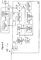
- amplifier system 600 includes a modulator section 603 and a switched power section 605.
- Switched power section 605 includes an opposed current switching circuit 607 that is responsive to PWM pulse drive signals 610 provided from the modulator section 603.
- the output of the opposed current switching circuit 607 may be provided to a summing circuit/output filter 613 that, in turn, provides the intended output signal 615 to a load 617.
- the intended output signal 615 may be used for negative feedback by providing it to the input of a combiner circuit 620 of the modulator section 603.
- the drive signals provided at the output of the opposed current switches may be provided to the input of the combiner circuit 620 along lines 619 for use in providing negative feedback.
- the combiner circuit 620 also accepts the signals at one or more lines 657.
- the output of the combiner circuit 620 is provided at one or more lines 623, which, in turn, is provided to the input of an analog-to-digital converter 625.
- the signal(s) 623 may be scaled, filtered, or otherwise processed in the analog domain so that further feedback processing in the digital domain may be simplified, if desired.
- the analog-to-digital converter 625 provides output signals at one or more lines 627 that correspond to the signals 623. These output signals are digitally processed by a feedback processor 650 along with digital signals 630 to generate a modified input signal 633.
- Digital signal 630 corresponds to an analog signal input 635 that has been converted to a digital format by analog-to-digital converter 637.
- Input signal 635 may constitute a signal that is directly provided to amplifier 600 for amplification or, alternatively, may constitute a processed signal that corresponds to the signal directly provided to amplifier 600 for amplification.
- Modulator section 603 includes a multiphase carrier generator 640 that generates digital representations of the various carrier signals that are PWM modulated using the modified input signal 633.
- a digital representation 643 of a first set of one or more analog carrier signals is provided to the input of intercept predictor 645.
- a digital representation 647 of a second set of one or more analog carrier signals is provided to the input of intercept predictor 651.
- the digitized carrier signals 643 and 647 may correspond to triangular modulator signals.
- the analog carrier signals represented by digitized carrier signals 643 differ in phase from the analog carrier signals represented by digitized carrier signals 647.
- the analog carrier signals represented by digitized carrier signals 643 may have phase vectors that evenly divide a unit circle.
- the analog carrier signals represented by digitized carrier signals 647 may be selected so that they evenly divide a unit circle at angles between the phase vectors corresponding to the analog signals represented by digitized carrier signals 643.
- the modified input signal 633 may be compared with the digitized carrier signals 643 by the intercept predictor 645 to determine where signals 633 and digitized carrier signals 643 will intercept one another. It is possible to use multiple input data samples on both sides in time of the expected time intercept point to compute a point of intercept. The determination of the intercept points can be calculated using interpolation/root-finding software implemented in, for example, a digital signal processor.
- the modified input signal 633 is compared with the digitized carrier signals 647 by the intercept predictor 651 to determine where signals 633 and digitized carrier signals 647 will intercept one another. Data indicating an intercept between signals 633 and 643 is provided to pulse generator 653 to generate interleaved PWM pulses 610.
- Data indicating an intercept between signals 633 and 647 may be used in a number of different manners to achieve the desired feedback effects.
- the intercept data may be provided to the input of a pulse generator 655 to generate interleaved PWM pulses 657 to the input of the combiner circuit 620.
- the digital output of intercept predictor 651 may be fed directly to the feedback processor 650.
- intermediate processing of the output of the intercept predictor 651, pulse generator 655, and/or combiner circuit 620 may be employed to, for example, perform any N N to N L ratio matching that may be desired.
- amplifier 600 may be integrated with one another, for example, on a common integrated circuit substrate.
- many of the components of modulator section 603 may be implemented by a digital signal processor and corresponding software.
- the modulator and feedback components of any of the foregoing amplifier systems are implemented in the analog domain, they may be efficiently implemented on a common integrated circuit substrate.
- Figure 7 illustrates a number of interrelated operations that may be used to implement one or more of the foregoing amplifiers.
- primary interleaved PWM pulses are generated from a modified input signal at block 705.
- the primary interleaved PWM pulses are used to drive the power stage of an interleaved PWM amplifier.
- Secondary interleaved PWM pulses are generated at block 715.
- the secondary interleaved pulses are generated using one or more carrier signals that differ in phase from the carrier signal(s) used to generate the primary interleaved PWM pulses at block 705.
- the modified input signal used at block 705 is generated from an input signal and both the primary and the secondary interleaved PWM pulses.
- Figure 8 illustrates a further set of interrelated operations that may be used to implement one or more of the foregoing amplifiers.
- primary interleaved PWM pulses are generated from a modified input signal at block 805.
- the primary interleaved PWM pulses are used to drive the power stage of an interleaved PWM amplifier.
- Secondary interleaved PWM pulses are generated at block 815.
- the secondary interleaved pulses are generated using one or more carrier signals that differ in phase from the carrier signal(s) used to generate the primary interleaved PWM pulses at block 805.
- the modified input signal used at block 805 is generated by combining an input signal, the secondary interleaved PWM pulses, and at feedback signal corresponding to the output signal from the power stage of the amplifier to, for example, a load.
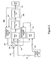
- FIG. 9 Another amplifier system 900 that employs interleaved PWM signals for PWM ripple suppression is illustrated in Figure 9 .
- the system 900 may be implemented in the analog domain, the digital domain, or combination of both.
- a signal 902 that is to be amplified by system 900 is provided at the input of a converter 905.
- the output of the converter 905 is provided to the input of an interleaved PWM generator 907.
- interleaved PWM generator 907 is implemented as a digital circuit
- converter 905 may be in analog-to-digital converter having the full resolution and linearity of the entire signal path through the amplifier system 900.
- converter 905 may be implemented as a gain stage that adapts to the prevailing input levels in filters the incoming signal to prevent aliasing with the PWM modulation process.
- the interleaved PWM generator 907 provides primary and secondary sets of interleaved PWM pulses in response to the signal provided from converter 905.
- the primary set of interleaved PWM pulses are provided at lines 909 and have an interleave order of N.
- the secondary set of interleaved PWM pulses are provided at lines 910 and have an interleave order of L.
- the interleaved PWM pulses of the primary set are generated by interleaved PWM generator 907 using carrier signals that differ in phase from the carrier signals used to generate the interleaved PWM pulses of the secondary set.
- interleave order N L and N >1.
- the correction signal(s) at line(s) 914 is derived from one or more feedforward signals corresponding to the secondary set of interleaved PWM pulses at lines 910. Additionally, the correction signal(s) may be derived from one or more feedback signals corresponding to the PWM modulated signals N" provided from the output of the interleaved PWM output stage 916.
- System 900 employs both feedforward and feedback circuit paths to facilitate derivation of the correction signal(s) from both the secondary set of interleaved PWM pulses and the PWM modulated signals N". To this end, the secondary set of interleaved PWM pulses at lines 910 are provided to the input of converter 920.
- Converter 920 provides a PWM waveform of appropriate response and amplitude to combine with a scaled version of the PWM modulated signals N".
- converter 920 converts a digital code to an analog pulse waveform of related width.
- converter 920 may perform signal scaling of the pulses at lines 910.
- the output of converter 920 may be provided to a positive terminal of a summing circuit 922 through a gain stage 924 having a transfer function H L .
- the transfer function H L may correspond to an attenuation and/or filtering operation that is designed to ensure that a proper relationship exists between the secondary set of interleaved PWM pulses and the PWM modulated signals N".
- any conversion, gain, and/or filtering operations may be executed in a single functional block or divided in a different manner between multiple functional blocks. Consequently, components used in the feedforward path of system 900 merely illustrate one manner in which such operations may be implemented.
- the PWM modulated signals N" may be provided to the input of a negative terminal of summing circuit 922 through a gain stage 926.
- gain stage 926 has a transfer function H N .
- the transfer function H N may correspond to an attenuation and/or filtering operation that is designed to ensure that a proper relationship exists between the PWM modulated signals N" and the secondary set of interleaved PWM pulses.
- the summing circuit 922 subtracts the signal at the output of the gain stage 926 from the output of the gain stage 924 to generate one or more error signals 928.
- the error signal(s) is a measure of the error between the ideal PWM signal output provided from the interleaved PWM generator 907 and the PWM modulated signals N" provided at the output of the interleaved PWM output stage 916.
- the error signal(s) 928 is amplified by an error amplifier 930 having a transfer function H E and optionally converted to an appropriate form by converter 932 for provision to the interleaved PWM corrector 912.
- converter 932 may comprise an analog-to-digital converter that converts the analog output from the error amplifier 932 an appropriate digital format for input to the interleaved PWM corrector 912.
- the conversion time of such an analog-two-digital converter may be selected so that it is very fast so as to avoid adding large amounts of phase lag to the feedback loop. Additionally, the dynamic range of such a converter also may be large. While the magnitude of the error signal should be smaller than the magnitude of the main signal, the errors that result from unregulated power supplies are quite large.
- the transfer function H E of the error amplifier 930 cascaded with the gain of the interleaved PWM output stage 916 and transfer function H N should be selected to meet the Nyquist stability criteria.
- the primary set of interleaved PWM pulses may be expected to be phased to evenly divide a unit circle. Thus, the secondary set of interleaved PWM pulses, used as reference signals, also may be phased phase to evenly divide the unit circle, just slightly lagging in phase to the primary set of interleaved PWM pulses.
- the error amplifier 930 may be implemented in a manner that facilitates creation of a conditionally stable feedback system having a high order of integration. To this end, the error amplifier 930 may be implemented using a high order passive RC differentiator for the feedback around one high gain inverting amplifier. An active clamp may be used around this feedback network to suppress out-of-control outputs that occur during system overload.
- Gain stages 924 and 926 may combine their interleaved inputs internally or pass them to their outputs for summing. Thus there are no signal counts shown in Figure 9 on the outputs for either stage. Both forms are logically equivalent in a linear network. Both signal paths may have the same relative amplitude and phase response to allow them to produce a zero difference when the interleaved PWM output stage 916 is errorless.
- the gain stage 926 also may receive low-pass filtered inputs 937 from the output filter 918. This may be done readily using high-order remote sensing methods where the high-frequency signal path comes from the interleaved PWM output stage 916 and the low-frequency signal path comes from the output filter 918.
- Figure 10 is a flow chart showing a number of interelated operations that may be executed in a system employing interleaved PWM signals for PWM ripple suppression.
- a first set of N interleaved PWM signals are generated at block 1005 and a second set of L interleaved PWM signals are generated at block 1010.
- the operations shown at blocks 1005 and 1010 may be executed concurrently.
- the first set of interleaved PWM signals at block 1005 are generated by modulating carrier signals numbering N with a signal that is to be amplified
- the second set of interleaved PWM signals at block 1010 are generated by modulating carrier signals numbering L with the signal that is to be amplified.
- the carrier signals used to generate the first set of interleaved PWM signals may differ in phase from the carrier signals used to generate the second set of interleaved PWM signals.
- an error signal is generated.
- the error signal is derived from the output signals of the interleaved PWM output stage and the second set of interleaved PWM signals that are generated at block 1010.
- This error signal is used at block 1020 to correct the pulse widths of the first interleaved PWM signals.
- the corrected interleaved PWM signals are used to drive the interleaved PWM output stage of the amplifier at block 1025.
- an amplifier comprises an interleaved PWM amplifier generating interleaved PWM pulses in response to a modified input signal and one or more carrier signals to drive a power stage of the interleaved PWM amplifier; an interleaved PWM generator providing interleaved PWM pulses in response to the modified input signal and one or more further carrier signals; and one or more feedback circuits responsive to an input signal and the interleaved PWM pulses of the interleaved PWM generator to generate the modified input signal.
- one or more further carrier signals may differ in phase from the one or more carrier signals used by the interleaved PWM amplifier to generate its interleaved PWM pulses.
- the one or more feedback circuits may comprise a first feedback circuit disposed to feedback an output of the power stage of the interleaved amplifier to generate a first feedback signal; a second feedback circuit disposed to feedback the interleaved PWM pulses of the PWM generator to generate a second feedback signal; a combiner circuit disposed to combine the input signal, the first feedback signal, and the second feedback signal to generate the modified input signal.
- the interleaved PWM amplifier and the first feedback circuit may combine to exhibit a first signal transfer characteristic
- the interleaved PWM generator and the second feedback circuit may combine to exhibit a second signal transfer characteristic
- the first and second transfer characteristics may be proportional to one another in about the same ratio as N L to N N over at least a predetermined portion of an output bandwidth of the amplifier
- N L is the interleave order of the interleaved PWM generator
- N N N is the interleave order of the interleaved PWM amplifier.
- the interleaved PWM amplifier has an interleave order of one.
- the amplifier comprises an interleaved PWM amplifier of interleave order N N >1, where the interleaved amplifier generates interleaved PWM pulses in response to a modified input signal and one or more carrier signals to drive a power stage of the interleaved PWM amplifier; an interleaved PWM generator of interleave order N L >1, where the interleaved PWM generator provides interleaved PWM pulses in response to the modified input signal and one or more further carrier signals; one or more feedback circuits combining an input signal and the interleaved PWM pulses of the interleaved PWM generator to generate the modified input signal.
- the one or more further carrier signals provided to the interleaved PWM generator differ in phase from the one or more carrier signals provided to the interleaved amplifier.
- N N and N L are even integers.
- the one or more feedback circuits comprise: a first feedback circuit disposed to feedback an output of the power stage of the interleaved amplifier to generate a first feedback signal; a second feedback circuit disposed to feedback the interleaved PWM pulses of the PWM generator to generate a second feedback signal; a combiner circuit disposed to combine the input signal, the first feedback signal, and the second feedback signal to generate the modified input signal.
- the interleaved PWM amplifier and the first feedback circuit combine to exhibit a first signal transfer characteristic
- the interleaved PWM generator and the second feedback circuit combine to exhibit a second signal transfer characteristic
- the first and second transfer characteristics are proportional to one another in about the same ratio as N L to N N over at least a predetermined portion of an output bandwidth of the amplifier.
- N N & N L are even integers.
- the amplifier comprises: a carrier generator circuit providing at least first and second carrier output signals; at least one pulse width modulator generating an interleaved pulse output drive signal in response to the first carrier output signal and a modified input signal; at least one opposed current output driver responsive to the interleaved pulse output drive signal of the at least one pulse width modulator to generate a load signal for use in driving a load; a feedback summing circuit responsive to first and second secondary feedback signals to generate the modified input signal to the at least one pulse width modulator; a first feedback circuit disposed to feed back at least a portion of the load signal as the first feedback signal of the feedback summing circuit; at least one further pulse width modulator generating a further interleaved pulse output signal in response to the second carrier output signal and the modified input signal; a second feedback circuit disposed to feed back at least a portion of the further interleaved pulse output signal as the second feedback signal of the feedback summing circuit.
- an amplifier comprises: an interleaved amplifier section receiving a modified input signal and providing an amplified output signal, where the interleaved amplifier section has a transfer characteristic G N corresponding to a first set of one or more phasing vectors; an interleaved PWM section receiving the modified input signal and providing an interleaved pulse output signal, where the interleaved PWM section has a transfer characteristic G L corresponding to a second set of one or more phasing vectors that are different from the first set of one or more phasing vectors; a summer circuit; a feedback circuit disposed to feedback at least a portion of the amplified output signal of the interleaved amplifier section to the summer circuit, where the feedback circuit has a transfer characteristic H N ; a further feedback circuit disposed to feedback at least a portion of the interleaved pulse output signal of the interleaved PWM
- G L ⁇ H L is nominally proportional to G N ⁇ H N over at least a predetermined portion of an output bandwidth of the amplifier.
- the transfer characteristic G N corresponds to an interleave order of N N and the transfer characteristic G L corresponds to an interleave order of N L ; and the proportionality of G L ⁇ H L to G N ⁇ H N is about N L to N N .
- the first set of phasing vectors are disposed at angles with one another to equally divide a circle.
- the second set of phasing vectors are disposed at angles with one another to equally divide a circle.
- the second set of phasing vectors equally divide a circle at angles offset from the first set of phasing vectors.
- the first and second set of phasing vectors combine to equally divide a circle.
- an amplifier comprises: an interleaved amplifier section receiving a modified input signal and providing an amplified output signal, where the interleaved amplifier section has a transfer characteristic a signal attenuator disposed to provide an attenuated output signal corresponding to the amplified output signal from the interleaved amplifier section; an interleaved PWM section receiving the modified input signal and providing an interleaved pulse output signal, where the interleaved PWM section has a transfer characteristic G L , and where the interleaved pulse output signal is generated using one or more further carrier signals; a delay circuit disposed to provide a delayed output signal corresponding to the interleaved pulse output signal of the interleaved PWM section; one or more combiner circuits generating the modified input signal based on the delayed output signal, the attenuated output signal, and an input signal that corresponds to a signal that is to be amplified.
- the one or more further carrier signals differ in phase from the one or more carrier signals used by the interleaved amplifier section.
- the one or more carrier signals used by the interleaved PWM section corresponds to a first set of phasing vectors, and the first set of phasing vectors are disposed at angles with one another to equally divide a circle.
- the one or more carrier signals used by the interleaved amplifier correspond to a second set of phasing vectors, and the second set of phasing vectors are disposed at angles with one another to equally divide a circle.
- the second set of phasing vectors equally divide a circle at angles offset from the first set of phasing vectors.
- the first and second set of phasing vectors combine to equally divide a circle.
- the one or more combiner circuits comprises a first combiner circuit generating a feedback signal as a sum of the attenuated output signal and the delayed output signal, and a second combiner circuit subtracting the feedback signal from the input signal.
- the amplifier further comprises a processing circuit disposed to process the feedback signal from the first combiner circuit, where the processed feedback signal is provided to the second combiner circuit.
- a method for operating an amplifier may comprise: generating primary interleaved PWM pulses in response to a modified input signal and one or more carrier signals; driving a power stage using the primary interleaved PWM pulses; generating secondary interleaved PWM pulse signals in response to the modified input signal and one or more further carrier signals; and generating the modified input signal from an input signal and the secondary interleaved PWM pulses.
- the one or more further carrier signals used to generate the secondary interleaved PWM pulse signals differ in phase from the one or more carrier signals used to generate the primary interleaved PWM pulse signals.
- the one or more carrier signals used to generate the primary interleaved PWM pulses have corresponding phasing vectors that are equal in magnitude and that equally divide a unit circle.
- the one or more further carrier signals used to generate the secondary interleaved PWM pulses have corresponding phasing vectors that are equal in magnitude and that equally divide a unit circle.
- the one or more further carrier signals used to generate the secondary interleaved PWM pulses have corresponding phasing vectors that are equal in magnitude and that equally divide a unit circle at an angle offset to the one or more carrier signals used to generate the primary interleaved PWM pulses.
- the one or more carrier signals and the one or more further carrier have corresponding phasing vectors that equally divide a unit circle.
- an amplifier comprises: an interleaved PWM generator providing primary and secondary sets of interleaved PWM pulses in response to an input signal; an interleaved PWM output stage responsive to corrected interleaved PWM pulses corresponding to the primary set of interleaved PWM pulses to generate amplified PWM output pulses; an interleaved PWM corrector responsive to one or more correction signals derived from one or more feedforward signals corresponding to the secondary set of interleaved PWM pulses to generate the corrected interleaved PWM pulses for use by the interleaved PWM output stage.
- the interleaved PWM pulses of the primary set are generated with carrier signals that differ in phase from carrier signals used to generate the interleaved PWM pulses of the secondary set.
- the interleaved PWM corrector is further responsive to one or more feedback signals corresponding to the amplified PWM output pulses to generate the corrected interleaved PWM pulses for use by the interleaved PWM output stage.
- the primary set of interleaved PWM pulses has an interleave order of N >1
- an amplifier comprises: an interleaved PWM generator providing primary and secondary sets of interleaved PWM pulses in response to an input signal; a feedforward circuit providing one or more feedforward signals derived from the secondary set of interleaved PWM pulses; an interleaved PWM output stage responsive to corrected interleaved PWM pulses corresponding to the primary set of interleaved PWM pulses to generate amplified PWM output pulses; a feedback circuit providing one or more feedback signals derived from the amplified PWM output pulses; an interleaved PWM corrector responsive to one or more correction signals derived from the one or more feedforward signals and the one or more feedback signals to generate the corrected interleaved PWM pulses for use
- the interleaved PWM pulses of the primary set are generated from carrier signals that differ in phase from carrier signals used to generate the interleaved PWM pulses of the secondary set.
- the primary set of interleaved PWM pulses is of an interleave order N
- the secondary set of interleaved PWM pulses is of an interleave order L
- N L.
- the feedforward circuit may comprise: a converter disposed to receive the secondary set of interleaved PWM pulses and a gain circuit having a transfer function H L .
- the feedback circuit may comprise a gain circuit having a transfer function H N .
- the amplifier may further comprise a summing circuit that provides one or more summed output signals corresponding to a difference between one or more signals provided at an output of the gain circuit of the feedback circuit and one or more signals provided at an output of the gain circuit of the feedforward circuit.
- the amplifier may further comprise a signal processing circuit responsive to the summed output signal to provide the one or more correction signals to the interleaved PWM corrector.
Applications Claiming Priority (2)
| Application Number | Priority Date | Filing Date | Title |
|---|---|---|---|
| US11/485,612 US7598714B2 (en) | 2006-07-12 | 2006-07-12 | Amplifier employing interleaved signals for PWM ripple suppression |
| EP07799447A EP2041867B1 (de) | 2006-07-12 | 2007-07-10 | Verstärker mit verschachtelten signalen für pwm-welligkeitsunterdrückung |
Related Parent Applications (2)
| Application Number | Title | Priority Date | Filing Date |
|---|---|---|---|
| EP07799447.3 Division | 2007-07-10 | ||
| EP07799447A Division EP2041867B1 (de) | 2006-07-12 | 2007-07-10 | Verstärker mit verschachtelten signalen für pwm-welligkeitsunterdrückung |
Publications (3)
| Publication Number | Publication Date |
|---|---|
| EP2221965A2 true EP2221965A2 (de) | 2010-08-25 |
| EP2221965A3 EP2221965A3 (de) | 2012-03-28 |
| EP2221965B1 EP2221965B1 (de) | 2016-06-22 |
Family
ID=38924099
Family Applications (2)
| Application Number | Title | Priority Date | Filing Date |
|---|---|---|---|
| EP07799447A Active EP2041867B1 (de) | 2006-07-12 | 2007-07-10 | Verstärker mit verschachtelten signalen für pwm-welligkeitsunterdrückung |
| EP10164465.6A Active EP2221965B1 (de) | 2006-07-12 | 2007-07-10 | Verstärker mit verschachtelten Signalen zur Unterdrückung der PWM-Schwankung |
Family Applications Before (1)
| Application Number | Title | Priority Date | Filing Date |
|---|---|---|---|
| EP07799447A Active EP2041867B1 (de) | 2006-07-12 | 2007-07-10 | Verstärker mit verschachtelten signalen für pwm-welligkeitsunterdrückung |
Country Status (6)
| Country | Link |
|---|---|
| US (3) | US7598714B2 (de) |
| EP (2) | EP2041867B1 (de) |
| JP (1) | JP4909412B2 (de) |
| CN (2) | CN102355209B (de) |
| DE (1) | DE602007009249D1 (de) |
| WO (1) | WO2008008777A2 (de) |
Families Citing this family (34)
| Publication number | Priority date | Publication date | Assignee | Title |
|---|---|---|---|---|
| US7598714B2 (en) * | 2006-07-12 | 2009-10-06 | Harman International Industries, Incorporated | Amplifier employing interleaved signals for PWM ripple suppression |
| US8099214B2 (en) * | 2009-02-09 | 2012-01-17 | GM Global Technology Operations LLC | Path planning for autonomous parking |
| JP5409152B2 (ja) * | 2009-07-14 | 2014-02-05 | 三菱重工業株式会社 | 電源装置 |
| US8760148B1 (en) * | 2010-07-21 | 2014-06-24 | Anritsu Company | Pulse modulated PIM measurement instrument |
| US9450548B2 (en) * | 2011-03-14 | 2016-09-20 | Samsung Electronics Co., Ltd. | Method and apparatus for outputting audio signal |
| KR101830883B1 (ko) * | 2011-03-14 | 2018-02-21 | 삼성전자주식회사 | 오디오 신호 출력 방법 및 그에 따른 오디오 신호 출력 장치 |
| US8750003B2 (en) * | 2011-06-16 | 2014-06-10 | Shlomo Ran Bet Esh | Device and method for DC to AC conversion |
| DE102011078452A1 (de) * | 2011-06-30 | 2013-01-03 | Robert Bosch Gmbh | Verfahren zum Ansteuern eines Wechselrichters eines Elektrowerkzeuges und Elektrowerkzeug |
| JP5230777B2 (ja) * | 2011-07-06 | 2013-07-10 | 三菱電機株式会社 | 電力変換装置 |
| US8410851B1 (en) | 2011-09-12 | 2013-04-02 | Wen-Hsiung Hsieh | Switching amplifier with an inductor |
| US8451057B2 (en) | 2011-11-02 | 2013-05-28 | Wen-Hsiung Hsieh | Switching amplifier using inductor current feedback |
| US9602067B2 (en) | 2011-11-15 | 2017-03-21 | Wen-Hsiung Hsieh | Switching amplifier with pulsed current supply |
| US8416020B1 (en) | 2011-11-20 | 2013-04-09 | Wen-Hsiung Hsieh | Switching amplifier and switching amplifying method |
| US8432221B1 (en) | 2011-11-27 | 2013-04-30 | Wen-Hsiung Hsieh | Switching amplifying method and switching amplifier |
| US8525587B2 (en) | 2011-12-04 | 2013-09-03 | Wen-Hsiung Hsieh | Switching amplifier with inductance means for transmitting energy |
| CN103246305A (zh) * | 2012-03-21 | 2013-08-14 | 上海拜安传感技术有限公司 | 基于反馈控制实现正负电压电流连续产生的电路结构 |
| US8760230B2 (en) | 2012-06-28 | 2014-06-24 | Wen-Hsiung Hsieh | Switching amplifier with pulsed current source and sink |
| US9210598B1 (en) | 2013-03-14 | 2015-12-08 | Anritsu Company | Systems and methods for measuring passive intermodulation (PIM) and return loss |
| US9941813B2 (en) | 2013-03-14 | 2018-04-10 | Solaredge Technologies Ltd. | High frequency multi-level inverter |
| US9331633B1 (en) | 2013-03-15 | 2016-05-03 | Anritsu Company | System and method for eliminating intermodulation |
| US9588212B1 (en) | 2013-09-10 | 2017-03-07 | Anritsu Company | Method of calibrating a measurement instrument for determining direction and distance to a source of passive intermodulation (PIM) |
| US9318974B2 (en) | 2014-03-26 | 2016-04-19 | Solaredge Technologies Ltd. | Multi-level inverter with flying capacitor topology |
| CN104242620B (zh) * | 2014-09-01 | 2017-07-28 | 成都芯源系统有限公司 | 具有纹波抑制电路的系统及其纹波抑制方法 |
| US9455792B1 (en) | 2015-01-21 | 2016-09-27 | Anritsu Company | System and method for measuring passive intermodulation (PIM) in a device under test (DUT) |
| US9768892B1 (en) | 2015-03-30 | 2017-09-19 | Anritsu Company | Pulse modulated passive intermodulation (PIM) measuring instrument with reduced noise floor |
| US9977068B1 (en) | 2015-07-22 | 2018-05-22 | Anritsu Company | Frequency multiplexer for use with instruments for measuring passive intermodulation (PIM) |
| US10069662B2 (en) * | 2015-11-10 | 2018-09-04 | Infineon Technologies Ag | Mixed analog-digital pulse-width modulator |
| CN106849653A (zh) * | 2015-12-04 | 2017-06-13 | 纬创资通(中山)有限公司 | 升压电路 |
| US10367430B2 (en) | 2016-01-11 | 2019-07-30 | Infineon Technologies Ag | System and method for a variable flow transducer |
| TWI578677B (zh) * | 2016-03-16 | 2017-04-11 | 國立成功大學 | 電力轉換裝置及其控制方法 |
| JP6666575B2 (ja) * | 2016-09-09 | 2020-03-18 | 理化工業株式会社 | 交流電力調整器 |
| CN107017762B (zh) * | 2017-02-21 | 2019-10-08 | 三峡大学 | 一种直流电容器谐波电流抑制方法 |
| US10998863B2 (en) | 2017-10-16 | 2021-05-04 | Analog Devices, Inc. | Power amplifier with nulling monitor circuit |
| US11275057B2 (en) | 2019-04-03 | 2022-03-15 | Infineon Technologies Ag | Photoacoustic sensor valve |
Family Cites Families (30)
| Publication number | Priority date | Publication date | Assignee | Title |
|---|---|---|---|---|
| US3715649A (en) * | 1967-01-25 | 1973-02-06 | Westinghouse Electric Corp | Staggered phase pulse width modulated inverter apparatus |
| JPS5626416U (de) * | 1979-08-08 | 1981-03-11 | ||
| US4843534A (en) * | 1987-11-13 | 1989-06-27 | Pacific Power Source Corp. | DC to AC switching converter with phased delayed parallel switchers |
| US5657219A (en) * | 1995-08-29 | 1997-08-12 | Crown International, Inc. | Opposed current power converter |
| DE69737882T2 (de) * | 1996-03-28 | 2008-03-13 | Texas Instruments Denmark A/S | Umwandlung eines pcm-signals in ein gleichmässig pulsbreitenmoduliertes signal |
| US5767740A (en) * | 1996-09-27 | 1998-06-16 | Harris Corporation | Switching amplifier closed loop dual comparator modulation technique |
| JP3346581B2 (ja) * | 1997-04-02 | 2002-11-18 | バング アンド オルフセン・パワーハウス・エイ/エス | パルス変調信号の強化されたパワー増幅用パルス基準制御方法及びシステム |
| CN1258393A (zh) * | 1998-01-22 | 2000-06-28 | 皇家菲利浦电子有限公司 | Pwm放大器 |
| JP2002532048A (ja) * | 1998-11-30 | 2002-09-24 | バング アンド オルフセン パワーハウス アクティーゼルスカブ | パルス幅変調電力コンバータ |
| JP2001127562A (ja) * | 1999-10-25 | 2001-05-11 | Susumu Kimura | Pwm電力増幅器 |
| CN100490286C (zh) * | 2000-01-03 | 2009-05-20 | 哈曼国际工业有限公司 | 调节功率转换器输出信号的方法、功率转换器及其放大器 |
| GB2360889B (en) * | 2000-03-31 | 2004-04-28 | Ling Dynamic Systems | High frequency switch-mode power amplifier |
| US6693571B2 (en) * | 2000-05-10 | 2004-02-17 | Cirrus Logic, Inc. | Modulation of a digital input signal using a digital signal modulator and signal splitting |
| US6373334B1 (en) * | 2000-06-12 | 2002-04-16 | Cirrus Logic, Inc. | Real time correction of a digital PWM amplifier |
| US6496060B2 (en) * | 2000-06-15 | 2002-12-17 | Nikon Corporation | Hybridized, high performance PWM amplifier |
| US7319763B2 (en) * | 2001-07-11 | 2008-01-15 | American Technology Corporation | Power amplification for parametric loudspeakers |
| US6683494B2 (en) | 2001-03-26 | 2004-01-27 | Harman International Industries, Incorporated | Digital signal processor enhanced pulse width modulation amplifier |
| US6449174B1 (en) * | 2001-08-06 | 2002-09-10 | Fairchild Semiconductor Corporation | Current sharing in a multi-phase power supply by phase temperature control |
| JP3941443B2 (ja) * | 2001-09-27 | 2007-07-04 | ヤマハ株式会社 | 自走式pwm増幅器 |
| US6795004B2 (en) * | 2001-09-28 | 2004-09-21 | Sony Corporation | Delta-sigma modulation apparatus and signal amplification apparatus |
| US6762704B1 (en) * | 2002-12-09 | 2004-07-13 | Cirrus Logic, Inc. | Modulation of a digital input signal using multiple digital signal modulators |
| US6949915B2 (en) * | 2003-07-24 | 2005-09-27 | Harman International Industries, Incorporated | Opposed current converter power factor correcting power supply |
| US7403400B2 (en) * | 2003-07-24 | 2008-07-22 | Harman International Industries, Incorporated | Series interleaved boost converter power factor correcting power supply |
| US6930483B2 (en) | 2003-08-01 | 2005-08-16 | General Electric Company | Method/system for switched frequency ripple reduction in MRI gradient coils |
| JP4731828B2 (ja) * | 2004-04-14 | 2011-07-27 | ルネサスエレクトロニクス株式会社 | D級アンプ |
| GB2419757B (en) | 2004-11-01 | 2008-11-26 | Zetex Plc | A digital amplifier |
| US7075346B1 (en) * | 2004-11-12 | 2006-07-11 | National Semiconductor Corporation | Synchronized frequency multiplier for multiple phase PWM control switching regulator without using a phase locked loop |
| JP4835012B2 (ja) * | 2005-03-18 | 2011-12-14 | ヤマハ株式会社 | D級増幅器 |
| JP4482812B2 (ja) * | 2005-03-29 | 2010-06-16 | ソニー株式会社 | アンプ出力制御装置、オーディオ装置及びアンプ出力制御方法 |
| US7598714B2 (en) * | 2006-07-12 | 2009-10-06 | Harman International Industries, Incorporated | Amplifier employing interleaved signals for PWM ripple suppression |
-
2006
- 2006-07-12 US US11/485,612 patent/US7598714B2/en active Active
-
2007
- 2007-07-10 CN CN201110343431.4A patent/CN102355209B/zh active Active
- 2007-07-10 WO PCT/US2007/073150 patent/WO2008008777A2/en active Application Filing
- 2007-07-10 EP EP07799447A patent/EP2041867B1/de active Active
- 2007-07-10 DE DE602007009249T patent/DE602007009249D1/de active Active
- 2007-07-10 JP JP2009519635A patent/JP4909412B2/ja active Active
- 2007-07-10 EP EP10164465.6A patent/EP2221965B1/de active Active
- 2007-07-10 CN CN200780033568.1A patent/CN101512897B/zh active Active
-
2009
- 2009-10-05 US US12/573,701 patent/US7969126B2/en active Active
- 2009-10-05 US US12/573,674 patent/US7876074B2/en active Active
Non-Patent Citations (1)
| Title |
|---|
| None |
Also Published As
| Publication number | Publication date |
|---|---|
| EP2041867A2 (de) | 2009-04-01 |
| JP4909412B2 (ja) | 2012-04-04 |
| US20100019846A1 (en) | 2010-01-28 |
| CN101512897A (zh) | 2009-08-19 |
| US20080012539A1 (en) | 2008-01-17 |
| CN102355209B (zh) | 2015-04-15 |
| EP2221965B1 (de) | 2016-06-22 |
| CN101512897B (zh) | 2012-01-25 |
| US20100019847A1 (en) | 2010-01-28 |
| DE602007009249D1 (de) | 2010-10-28 |
| JP2009544192A (ja) | 2009-12-10 |
| WO2008008777A3 (en) | 2008-05-02 |
| EP2041867B1 (de) | 2010-09-15 |
| WO2008008777A2 (en) | 2008-01-17 |
| EP2221965A3 (de) | 2012-03-28 |
| US7969126B2 (en) | 2011-06-28 |
| CN102355209A (zh) | 2012-02-15 |
| US7598714B2 (en) | 2009-10-06 |
| US7876074B2 (en) | 2011-01-25 |
Similar Documents
| Publication | Publication Date | Title |
|---|---|---|
| EP2221965B1 (de) | Verstärker mit verschachtelten Signalen zur Unterdrückung der PWM-Schwankung | |
| EP2304871B1 (de) | Schaltleistungsverstärker und verfahren zu seiner steuerung | |
| JP2006512004A (ja) | デジタル信号変調器を用いたデジタル入力信号の変調および信号の分割 | |
| EP1985013A2 (de) | Systeme und verfahren zur verbesserung der leistungsfähigkeit in einem digitalen verstärker durch addieren eines ultraschallsignals zu einem eingangsaudiosignal | |
| GB2432470A (en) | System for dynamic time offsetting in interleaved power amplifiers | |
| US8179957B2 (en) | Quadrature pulse-width modulation methods and apparatus | |
| EP2127078B1 (de) | Verfahren und vorrichtung zur herstellung dreieckiger kurven mit geringem audiobandgeräuschanteil | |
| US7170360B2 (en) | Device and method for digital pulse width modulation | |
| EP1588484B1 (de) | Pulsmodulierter stromwandler | |
| US6963189B2 (en) | Attenuation control for digital power converters | |
| GB2456889A (en) | A PWM modulator for a Cartesian transmitter | |
| KR20010089521A (ko) | 펄스폭 변조 전력 변환기 | |
| JP4736630B2 (ja) | Dクラスアンプ | |
| US20090091382A1 (en) | Audio signal processing system and method | |
| US9887670B2 (en) | Power supply circuit, high-frequency power amplification circuit, and power supply control method | |
| EP1971023B1 (de) | Unterdrückung von Hochfrequenzstörungen für Pulsweiten-Modulation | |
| JP5733838B2 (ja) | D級増幅器 | |
| JPWO2019026669A1 (ja) | 無線機及び無線出力増幅方法 | |
| JP2007005957A (ja) | デジタルアンプ | |
| JPH09223935A (ja) | 搬送波pdm形振幅変調装置 | |
| JP2007005980A (ja) | D級アンプ | |
| JP2008017273A (ja) | デジタル振幅変調送信機 |
Legal Events
| Date | Code | Title | Description |
|---|---|---|---|
| PUAI | Public reference made under article 153(3) epc to a published international application that has entered the european phase |
Free format text: ORIGINAL CODE: 0009012 |
|
| AC | Divisional application: reference to earlier application |
Ref document number: 2041867 Country of ref document: EP Kind code of ref document: P |
|
| AK | Designated contracting states |
Kind code of ref document: A2 Designated state(s): DE FR GB IT |
|
| PUAL | Search report despatched |
Free format text: ORIGINAL CODE: 0009013 |
|
| AK | Designated contracting states |
Kind code of ref document: A3 Designated state(s): DE FR GB IT |
|
| RIC1 | Information provided on ipc code assigned before grant |
Ipc: H03F 3/217 20060101AFI20120220BHEP Ipc: H03K 17/16 20060101ALI20120220BHEP Ipc: H03K 7/08 20060101ALI20120220BHEP Ipc: H03F 1/32 20060101ALI20120220BHEP |
|
| 17P | Request for examination filed |
Effective date: 20120927 |
|
| 17Q | First examination report despatched |
Effective date: 20150331 |
|
| GRAP | Despatch of communication of intention to grant a patent |
Free format text: ORIGINAL CODE: EPIDOSNIGR1 |
|
| INTG | Intention to grant announced |
Effective date: 20160205 |
|
| GRAS | Grant fee paid |
Free format text: ORIGINAL CODE: EPIDOSNIGR3 |
|
| GRAA | (expected) grant |
Free format text: ORIGINAL CODE: 0009210 |
|
| AC | Divisional application: reference to earlier application |
Ref document number: 2041867 Country of ref document: EP Kind code of ref document: P |
|
| AK | Designated contracting states |
Kind code of ref document: B1 Designated state(s): DE FR GB IT |
|
| REG | Reference to a national code |
Ref country code: GB Ref legal event code: FG4D |
|
| REG | Reference to a national code |
Ref country code: DE Ref legal event code: R096 Ref document number: 602007046753 Country of ref document: DE |
|
| PG25 | Lapsed in a contracting state [announced via postgrant information from national office to epo] |
Ref country code: IT Free format text: LAPSE BECAUSE OF FAILURE TO SUBMIT A TRANSLATION OF THE DESCRIPTION OR TO PAY THE FEE WITHIN THE PRESCRIBED TIME-LIMIT Effective date: 20160622 |
|
| REG | Reference to a national code |
Ref country code: DE Ref legal event code: R097 Ref document number: 602007046753 Country of ref document: DE |
|
| PG25 | Lapsed in a contracting state [announced via postgrant information from national office to epo] |
Ref country code: FR Free format text: LAPSE BECAUSE OF NON-PAYMENT OF DUE FEES Effective date: 20160822 |
|
| PLBE | No opposition filed within time limit |
Free format text: ORIGINAL CODE: 0009261 |
|
| REG | Reference to a national code |
Ref country code: FR Ref legal event code: ST Effective date: 20170331 |
|
| STAA | Information on the status of an ep patent application or granted ep patent |
Free format text: STATUS: NO OPPOSITION FILED WITHIN TIME LIMIT |
|
| GBPC | Gb: european patent ceased through non-payment of renewal fee |
Effective date: 20160922 |
|
| 26N | No opposition filed |
Effective date: 20170323 |
|
| PG25 | Lapsed in a contracting state [announced via postgrant information from national office to epo] |
Ref country code: GB Free format text: LAPSE BECAUSE OF NON-PAYMENT OF DUE FEES Effective date: 20160922 |
|
| REG | Reference to a national code |
Ref country code: DE Ref legal event code: R082 Ref document number: 602007046753 Country of ref document: DE Representative=s name: MAUCHER JENKINS PATENTANWAELTE & RECHTSANWAELT, DE |
|
| P01 | Opt-out of the competence of the unified patent court (upc) registered |
Effective date: 20230527 |
|
| PGFP | Annual fee paid to national office [announced via postgrant information from national office to epo] |
Ref country code: DE Payment date: 20230620 Year of fee payment: 17 |