EP2221614A1 - Microstructure inspecting device, and microstructure inspecting method - Google Patents
Microstructure inspecting device, and microstructure inspecting method Download PDFInfo
- Publication number
- EP2221614A1 EP2221614A1 EP08854451A EP08854451A EP2221614A1 EP 2221614 A1 EP2221614 A1 EP 2221614A1 EP 08854451 A EP08854451 A EP 08854451A EP 08854451 A EP08854451 A EP 08854451A EP 2221614 A1 EP2221614 A1 EP 2221614A1
- Authority
- EP
- European Patent Office
- Prior art keywords
- microstructure
- moving portion
- insulating layer
- wave generating
- heat
- Prior art date
- Legal status (The legal status is an assumption and is not a legal conclusion. Google has not performed a legal analysis and makes no representation as to the accuracy of the status listed.)
- Withdrawn
Links
Images


Classifications
-
- G—PHYSICS
- G01—MEASURING; TESTING
- G01N—INVESTIGATING OR ANALYSING MATERIALS BY DETERMINING THEIR CHEMICAL OR PHYSICAL PROPERTIES
- G01N29/00—Investigating or analysing materials by the use of ultrasonic, sonic or infrasonic waves; Visualisation of the interior of objects by transmitting ultrasonic or sonic waves through the object
- G01N29/04—Analysing solids
- G01N29/12—Analysing solids by measuring frequency or resonance of acoustic waves
-
- G—PHYSICS
- G01—MEASURING; TESTING
- G01N—INVESTIGATING OR ANALYSING MATERIALS BY DETERMINING THEIR CHEMICAL OR PHYSICAL PROPERTIES
- G01N29/00—Investigating or analysing materials by the use of ultrasonic, sonic or infrasonic waves; Visualisation of the interior of objects by transmitting ultrasonic or sonic waves through the object
- G01N29/14—Investigating or analysing materials by the use of ultrasonic, sonic or infrasonic waves; Visualisation of the interior of objects by transmitting ultrasonic or sonic waves through the object using acoustic emission techniques
Definitions
- the present invention relates to a device and method for inspecting a microstructure including a moving portion.
- microstructure devices for example, various sensors using MEMS(Micro Electro Mechanical Systems)
- MEMS Micro Electro Mechanical Systems
- electronic devices have been made small and light and have high-level functions
- MEMS Micro Electro Mechanical Systems
- the development of MEMS has also been promoted. Since MEMS are micro-fabricated systems, there is a demand for an appropriate method of inspecting the MEMS.
- Examples of a method of measuring mechanical characteristics, such as an attenuation factor ( ⁇ ), a Q value, a natural frequency (f0), and a loss factor ( ⁇ ), of a microstructure include a method of obtaining a decay curve by using an impulse hammer, and a method of obtaining a resonance frequency by intentionally scanning an excitation frequency of a structure and thus obtaining an attenuation factor from a FWHM(Full Width at Half Maximum) of a resonance curve.
- Patent Document 1 or Patent Document 2 discloses a method of causing a test sound wave to be output from a speaker to a moving portion of a sensor to move the moving portion, and thus inspecting electrical characteristics of a microstructure by using a probe.
- Patent Document 3 discloses a method of detecting a change in the resistance value of an acceleration sensor formed on a wafer by blowing air and thus determining the property of the acceleration sensor.
- Patent Document 4 discloses a method of outputting an ultrasonic wave to a moving portion to induce slow dynamics on an object, and measuring a physical change.
- Patent Document 5 discloses a method of intermittently generating a longitudinal wave by using a sound wave generating element of thermal excitation type, and thus detecting a distance to an object and an orientation where the object is located.
- Patent Document 6 discloses a method of causing a PZT (lead zirconate titanate) ultrasonic wave transforming device to directly contact a microstructure, and thus measuring a dynamic response.
- PZT lead zirconate titanate
- the method using the impulse hammer indirectly moves the moving portion by passing through a support member of the microstructure and a support unit of the moving portion of the microstructure, and the like. Accordingly, since the impact time or intensity of impact to be applied to the moving portion cannot be precisely controlled, the degree of measurement precision of the decay curve is not high. Also, with respect to a DUT (die under tester: chip-state sample) having a low Q value, since an impact time and a decay time are almost the same, damping characteristics or the Q value cannot be measured. Also, the method disclosed in the Patent Document 6 cannot directly excite the moving portion of the microstructure. Accordingly, vibration of a package (PKG) or a support case body overlaps with a signal line or reverberation of an impact source overlaps, thereby resulting in a decrease in the degree of measurement precision.
- PKG package
- a support case body overlaps with a signal line or reverberation of an impact source overlaps, thereby resulting in a decrease in the degree of measurement precision.
- the microstructure Since electrical characteristics of the microstructure are inspected by using the impulse hammer, the microstructure cannot be directly excited, and thus the microstructure has been excited in the form of a package (PKG). Accordingly, since defective products can be detected only in a final step of a manufacturing process, even though defects occur in the middle of the manufacturing process, the manufacturing process proceeds to the final step, thereby leading waste of time and money. Also, defect analysis and solution on defects is delayed, thereby reducing efficiency.
- the present invention is proposed considering the aforementioned state of art. According to the present invention a microstructure inspecting device and method capable of precisely and reproducibly controlling impact time and intensity and performing measurement with a high degree of precision may be provided.
- a microstructure inspecting device which measures a damping characteristic value of a moving portion of a microstructure, the microstructure inspecting device including an impact applying unit which applies an impact to the moving portion by using a pressure wave generation device that does not directly contact the microstructure; and a measuring unit which measures a displacement of the moving portion for a predetermined period of time after the start of free vibration of the moving portion, without contacting the moving portion.
- the impact applying unit may include a sound wave generating element of thermal excitation type, and a driving unit which inputs a pulse signal to the sound wave generating element.
- the sound wave generating element of thermal excitation type may include a thermally conductive substrate; a heat-insulating layer formed of nano-crystal silicon in one principal surface of the substrate; an insulating layer formed on the heat-insulating layer; and a conductive layer formed on the insulating layer and emitting heat when being supplied with current containing alternating current components.
- a microstructure inspecting method including: applying an impact to a moving portion of a microstructure by using a pressure wave generating device that does not directly contact the microstructure; causing the moving portion to freely vibrate; and measuring a displacement of the moving portion during a predetermined period of time after the start of the free vibration of the moving portion, without contacting the moving portion.
- the pressure wave generating device may be a sound wave generating element of thermal excitation type.
- the sound wave generating element of thermal excitation type may include a thermally conductive substrate; a heat-insulating layer formed of nano-crystal silicon in one principal surface of the substrate; an insulating layer formed on the heat-insulating layer; and a conductive layer formed on the insulating layer and emitting heat when being supplied with current containing alternating current components.
- the microstructure inspecting method may further include calculating a Q value of the microstructure from the displacement of the moving portion measured in the measuring step; and determining that the microstructure is normal when the Q value is within a predetermined range, and determining that the microstructure is defective when the Q value is not within the predetermined range.
- the microstructure inspecting method may further include feeding back the Q value calculated in the calculating step, and a determined result in the determining step to a control device that sets a manufacturing condition of a manufacturing device for manufacturing the microstructure.
- the microstructure inspecting device of the present invention since impact time or intensity can be precisely and reproducibly controlled, the degree of measurement precision of vibration damping characteristics of a microstructure is improved.
- FIG. 1 is a block diagram showing an example of a configuration of a microstructure inspecting device according to an embodiment of the present invention.
- FIG. 2A is a plan view showing connection of a driving circuit of a pressure wave generating device 1 shown in FIG. 1 .
- FIG. 2B is a cross-sectional view taken along line X-X of FIG. 2A .
- a microstructure inspecting device 10 includes the pressure wave generating device 1, a pulse generating device 2, an amplifying unit 3, a vibrometer 4, a calculating unit 5, a support unit 6, a chuck 7, and an inspecting stage 8.
- the pressure wave generating device 1 is supported by the support unit 6 and is installed on the inspecting stage 8.
- a sample S is placed to face a surface of the pressure wave generating device 1 on which a pressure wave is generated, and a wafer W having the sample S is supported by the chuck 7.
- the microstructure inspecting device 10 used the pressure wave generating device 1 in order to excite the sample S.
- a sound wave generating element of thermal excitation type is used in order to generate a pressure wave, and uses a longitudinal wave, which is generated by heating and cooling air by using a heater, as a sound wave. Accordingly, impact time or intensity can be precisely and reproducibly controlled by using the heater. Since a speaker including a vibration plate having elasticity and mass is not used, there is no risk of reverberation. Also, if the mass of the vibration plate is negligible and a moving portion can vibrate without contacting the sample S, a piezoelectric sound wave generating element may be used in order to generate a pressure wave. Also, by forming a coil around a microstructure, an impact may be directly applied to the sample S by exciting the coil through electromagnetic induction.
- the pressure wave generating device 1 includes a substrate 12, a heat-insulating layer 13, a heating element 14, and an insulating layer 15.
- a driving circuit 16 is electrically connected to both ends of the heating element 14.
- the substrate 12 is formed of bulk silicon or the like.
- the heat-insulating layer 13 formed of porous nano-crystal silicon (hereinafter, referred to as nc-Si) is formed in one principal surface of the substrate 12.
- the insulating layer 15 is formed in the surface of the substrate 12, in which the heat-insulating layer 13 is formed, to contact the heat-insulating layer 13.
- the insulating layer 15 is formed of a thin film of an insulating material such as silicon nitride (Si 3 N 4 ), silicon dioxide (SiO 2 ), aluminum oxide (Al 2 O 3 ), or the like.
- the heating element 14 having a heater pattern is formed of a thin film of a electrically conductive metal, for example, tungsten (W), platinum (Pt), or gold (Au), to contact a top of the insulating layer 15.
- the driving circuit 16 applies an intermittent pulse voltage, or an alternating current voltage, at a predetermined frequency ⁇ to both ends of the heating element 14.
- the thickness of the heat-insulating layer 13, with respect to alternating current components of the voltage applied to the heating element 14, is about the same as a thermal diffusion length determined by the thermal conductivity and heat capacity per unit volume of the heat-insulating layer 13. Accordingly, alternating current components of emitted heat to the substrate 12 side are insulated and direct current components of the emitted heat generated due to the heat capacity of the heating element 14 may efficiently diffuse to the substrate 12 having high thermal conductivity.
- the thickness of the heat-insulating layer 13 may vary according to a frequency of a sound wave generated, the thickness of the heat-insulating layer 13 may range, for example, from about 5 ⁇ m to about 200 ⁇ m.
- the thickness of the insulating layer 15 is sufficiently less than the thermal diffusion length, and thus the alternating current components of the emitted heat of the heating element 14 are insulated in a thickness direction of the heat-insulating layer 13.
- the insulating layer 15 conducts heat in a surface direction. Since the heating element 14 is closely attached to the insulating layer 15, the insulating layer 15 operates to make the temperature of the heating element 14 uniform. Since the insulating layer 15 does not allow electricity to pass therethrough, the insulating layer 15 does not emit heat, and reduces local thermal stress of the heating element 14 by making the temperature of the heating element 14 uniform. Accordingly, even with a voltage leading to breaking of wire which a conventional pressure wave generating device may encounter, the heating element 14 rarely undergoes deformation or breaking of wire. As a result, it is possible to increase the sound pressure of a sound wave generated by the pressure wave generating device 1.
- the insulating layer 15 has high thermal conductivity in an in-plane direction, and does not absorb heat in a thickness direction. Accordingly, the insulating layer 15 may be thinly formed of a material having high thermal conductivity and low specific heat.
- the insulating layer 15 may be formed of a material, for example, magnesium oxide (MgO), diamond crystalline carbon (C), aluminum nitride (AIN), or silicon carbide SiC as well as the aforesaid silicon nitride (Si 3 N 4 ), silicon dioxide (SiO 2 ), or aluminum oxide (Al 2 O 3 ).
- the thickness of the insulating layer 15 ranges, for example, about 50 nm to about 200 nm.
- the heating element 14 is not limited to a specific material if the heating element 14 is formed of a metal film.
- the heating element 14 may be formed of a metal simple substance such as tungsten (W), molybdenum (Mo), iridium (Ir), gold (Au), aluminum (Al), nickel (Ni), titanium (Ti), and platinum (Pt), or a stacked structure thereof.
- the heating element 14 may be formed by vacuum deposition, sputtering, or the like.
- the thickness of the metal film is as small as possible in order to reduce heat capacity, the thickness of the film may be selected from a range of 10 nm to 300 nm in order to have appropriate resistance.
- the substrate 12 of a silicon wafer is prepared, and an electrode layer formed of a thin film of, for example, aluminum, is formed on an inner surface by vacuum deposition or the like.
- anodizing is performed by using a mixture solution of hydrofluoric acid (HF) and ethanol on a portion where the heat-insulating layer 13 is to be formed by using platinum (Pt) as a counter electrode.
- the heat-insulating layer 13 having a desired thickness and grain size and formed of porous nc-Si is formed by controlling a component ratio of the solution, current density, and a processing time to have predetermined values.
- the insulating layer 15 is formed on the surface of the substrate 12 in which the heat-insulating layer 13 is formed.
- Non-doped silicate glass (NSG) or the like is deposited on the substrate 12 by using, for example, plasma CVD, to form the insulating layer 15.
- a stencil mask S patterned to have the shape of the heating element 14 is held on the insulating layer 15, and the heating element 14 is formed to have a predetermined pattern on the insulating layer 15 by gold (Au) sputtering.
- Au gold
- an electrode or the like for connecting the driving circuit 16 to the heating element 14 is formed, and the electrode layer formed on the inner surface undergoes removal, polishing, or the like if necessary.
- a voltage transmitted from the pulse generating device 2 is amplified to become a plurality of pulse voltages or a pulse voltage having a desired time width by the amplifying unit 3, and is applied in burst shape to the heating element 14 of the pressure wave generating device 1.
- the heating element 14 generates a pressure wave of an impulse by heating and cooling an ambient air layer, and radiates the pressure wave to the sample S to excite the sample S. Due to the excitation, a moving portion of the sample S starts damped vibraton. The vibration of the moving portion is measured by using the vibrometer 4, for example, a non-contact type laser vibrometer.
- the pressure wave generating device 1 can precisely and reproducibly control impact time or intensity, a sound pressure enough to measure can be obtained, thereby increasing the degree of measurement precision. Also, the pressure wave generating device 1 does not have the influence of reverberation of an impulse source when the pressure is applied, thereby not having the influence of noise. Also, since the pressure wave generating device 1 can directly excite the microstructure so that the microstructure does not have to contact the sample S to measure the amount of displacement, the pressure wave generating device 1 doesn't affect the damped vibraton of the moving portion.
- the amount of displacement measured by the vibrometer 4 may be calculated as an damped vibraton pattern by the calculating unit 5 to obtain a resonance frequency or a Q value. If the obtained value is not within a predetermined numerical range, it is determined that there is abnormality and thus good products and defective products can be distinguished.
- a Q value which is a dimensionless number primarily indicating the state of vibration, is related to loss of energy due to absorption by a medium, in the propagation of elastic waves.
- the Q value is energy obtained by dividing energy stored in a system during one period by energy dissipated in the system, where a larger Q value indicates greater vibration stability. If the Q value is high, it means that the state of vibration is stable, and a startup time is long and the distribution of vibration energy is high.
- a resonance frequency is obtained from a value obtained by converting a vibration pattern into a frequency spectrum by using Fourier transform.
- a Q value is obtained from a gradient of a spectrum graph that is obtained by converting the vibration pattern by using Hilbert transform.
- an object to be inspected is a MEMS
- structural defects in a pressure sensor, a gyro sensor, or the like can be detected by using a Q value.
- FIG. 3 is a block diagram showing a configuration of a manufacturing system including a semiconductor manufacturing device and the microstructure inspecting device 10 according to the embodiment of the present invention.
- a representative semiconductor manufacturing process includes a pre-process and a post-process, wherein the pre-process includes a circuit design, a patterns design, a photomask making, a wafer manufacturing, and elements formation, and the post-process includes assembly, final inspection and marking.
- the semiconductor manufacturing device shown in FIG. 3 is a photolithography/etching processing device 20 of a microstructure (MEMS) (hereinafter, referred to as a processing device 20) and is used in the wafer manufacturing process.
- MEMS microstructure
- the microstructure inspecting device 10 is the same as that shown in FIG. 1 and an explanation thereof will be omitted.
- the calculating unit 5 of the microstructure inspecting device 10 is connected to a control unit 40 of the processing device 20.
- the control unit 40 includes a calculation processing device and a ROM that stores a processing program and the like, and controls the whole processing device 20 and individual systems constituting the processing device 20.
- the processing device 20 includes a cassette station 21 and a processing station 22.
- the cassette station 21 transfers wafers W, which are supplied from the outside in the unit of a wafer cassette, from cassettes 23 to the processing device 20, or transfers the wafers W having been processed from the processing device 20 to the cassettes 23.
- the processing station 22 includes a plurality of processing units, and performs photolithography/etching while sequentially moving the wafers W to each of the processing units.
- a cassette holding stage 24 is formed in the cassette station 21, and one of the cassettes 23 in which a wafer W to be processed is stored is supplied from the outside. Also, in the cassette holding stage 24, a wafer W having been processed is stored in a cassette 23 to be transferred out. Transfer of a wafer W on the cassette holding stage 24 is performed by a station transfer mechanism 25.
- the station transfer mechanism 25 can move horizontally (in a direction marked by a solid arrow) and vertically (in a direction perpendicular to the ground) so as to access the plurality of cassettes 23 placed on the cassette holding stage 24. Also, the station transfer mechanism 25 can rotate (in a direction marked by a dotted arrow) so as to transfer the wafer W from the processing station 22 to the cassette holding stage 24.
- a plurality of photolithography/etching processing units (processing units 26 through 28), a unit transfer mechanism 29, and a temporarily-holding stage 30 are formed in the processing station 22.
- a resist pattern is formed in the processing unit 26.
- Etching is performed in the processing unit 27.
- a film is formed and the resist is removed in the processing unit 28.
- a wafer W transferred to the processing station 22 is placed on the temporarily-holding stage 30, and the unit transfer mechanism 29 starts to act as a transfer mechanism instead of the station transfer mechanism 25. Due to the unit transfer mechanism 29, the wafer W is sequentially transferred in the order of the processing unit 26, the processing unit 27, and the processing unit 28 so that photolithography/etching is performed on the wafer W. The wafer W on which the processing has been completed is placed on the temporarily-holding stage 30 again, and is transferred from the processing station 22 by the station transfer mechanism 25.
- the unit transfer mechanism 29 can move horizontally and vertically, and rotate, like the station transfer mechanism 25.
- a resist pattern is formed in the processing unit 26.
- the wafer W transferred to the processing unit 26 is covered with a photomask due to a resist spread.
- the wafer W covered with the photomask is exposed and developed, to form a resist having a desired shape (pattern) on the wafer W.
- the resist is cured by heating to be adhered to the wafer W. If exposure or development is insufficient, the resist may be deformed to have a pattern other than the desired pattern.
- Etching is performed in the processing unit 27. Although there are wet etching and dry etching, wet etching will be explained herein.
- the wafer W is immersed in an etching solution such as hydrogen fluoride or the like, and a portion of the wafer W not covered with the resist is etched. A portion of the wafer W protected by the resist is not etched and thus the same shape as the shape of the resist is bulgingly formed on the wafer W.
- An etching state varies according to the temperature or time of the etching solution, and also, as an etching depth increases, etching may occur even in a portion directly under the resist.
- a film is formed and the resist is removed in the processing unit 28.
- a layer formed of a metal or an oxide film is formed on the wafer W by using vacuum deposition, sputtering, or the like.
- the resist is completely removed by using a resist solvent or the like. Since a film formed on the resist is also removed during the removal of the resist, a desired pattern can be added to the upper surface of the wafer W.
- a microstructure having a complex structure after processing in the processing unit 28, photolithography/etching is repeatedly performed in processing units(not shown) 26a, 27a, 28a through 26n, 27n, and 28n. Also, the microstructure is manufactured by machanoelectric conversion device formation, wire formation, and the like as well as performing photolithography/etching.
- the wafer W in which the microstructure is formed is engaged on the microstructure inspecting device 10.
- the microstructure which is a sample S, is located facing an output portion of the pressure wave generating device 1, and the wafer W is supported by the chuck 7.
- a voltage transmitted from the pulse generating device 2 is amplified to a plurality of pulse voltages or a pulse voltage having a desired time width by the amplifying unit 3, and is applied in a burst shape to the heating element 14 of the pressure wave generating device 1.
- the heating element 14 generates a pressure wave of an impulse by heating and cooling an ambient air layer, and radiates the pressure wave to the sample S to excite the sample S. Since the sample S is directly excited, there is no influence of reverberation or noise.
- a moving portion of the sample S starts damped vibraton due to the excitation.
- the vibration of the moving portion is measured by using the vibrometer 4, for example, a laser Doppler vibrometer.
- measuring of displacement of the sample S by the vibrometer 4 is performed for a predetermined period of time after the start of free vibration of the sample S. That is, the pressure wave generating device 1 (speaker) radiates the pressure wave to the sample S (the moving portion) to enable the sample S to vibrate. Next, the pressure wave generating device 1 stops the radiation of the pressure wave to the sample S to enable the sample S to freely vibrate. And, the vibrometer 4 measures the displacement of the sample S while the sample S is freely vibrating.
- free vibration refers to vibration of the moving portion in a state where reverberation of the speaker or other peripheral equipment is zero or negligible. While the sample S is freely vibrating, external influence is zero.
- the nano-crystal silicon speaker is suitable for such a measurement system.
- a measured damped vibraton pattern is numerically processed by the calculating unit 5 to calculate a resonance frequency and a Q value, and thus it is determined whether the microstructure is good or bad. If the resonance frequency exceeds a designated numerical range, it may be found that a spring constant of the moving portion of the microstructure is abnormal. If the Q value exceeds a preset range, it is found that the structure of a sensor is abnormal. For example, damage to the microstructure may be occurred or film thickness may be abnormal.
- Analysis of causes of defects is performed based on abnormality in the resonance frequency or the Q value. If the resonance frequency is low, it is possible that the moving portion is small or the support unit is thin due to, for example, over-etching. Also, if the Q value is low, that is, if vibration is immediately reduced, it is possible that the microstructure is damaged. It is possible that the resist formation is not performed well, the wafer W is not sufficiently protected, the wafer W is excessively etched, and thus the resist fails to have a desired shape. Alternatively, since a film is not formed well, thick or thin film formation or the like may occur.
- Information about the measured resonance frequency and the Q value of the microstructure is fed back from the calculating unit 5 to the control unit 40. If there is a feedback of information indicating that the value is out of a preset desired numerical range that means the microstructure is in a good state, conditions for predicted questions and corresponding solutions are set according to a state of abnormal value, so that a control instruction may be output to a corresponding system from the control unit 40. Also, a program of the control unit 40 may be previously set so that a buzzer sound or flash light is occurred from an external device connected to the control unit 40 to indicate abnormality. If both the resonance frequency and the Q value are abnormal, it is possible to set the processing station 22 to temporarily stops.
- a control instruction is output from the control unit 40 to the processing unit 27 to suitably change etching conditions or the like. If the Q value is much different from a desired value, it is possible that damage to the microstructure is occurred. It is possible that the resist is not formed to have a desired shape and thus the resist fails to protect the wafer W during etching.
- a control instruction is transmitted from the control unit 40 to the processing unit 26 where the resist is formed, to suitably change conditions for photolithography, etc.
- a control instruction is transmitted from the control unit 40 to the processing unit 28, to suitably change conditions for film formation.
- the trend of the manufacturing state may be kept track of by accumulating fed-back measurement data and repeatedly reflecting the measurement data. Also, when the measurement results indicate good products, adjusting various conditions by automatic control is helpful in performing the manufacturing process while maintaining product quality constant.
- the wafer W of which measurement has been completed is transferred to a next process at the same time as the control unit 40 feeds back the measurement results. Accordingly, since processing conditions of the wafer W on which the microstructure is formed can be adjusted by automatic control from now on, generation of defective products can be prevented. Also, since the microstructure of which the resonance frequency and the Q value was abnormal is checked, the microstructure can be discarded after cutting off of a chip. Accordingly, defective products can be removed without bringing the manufacturing process to a final step.
- the microstructure inspecting method according to the present invention can precisely and reproducibly control impact time or intensity, the degree of measurement precision of vibration damping characteristics of a microstructure is improved. Also, it is helpful in performing the manufacturing process while maintaining product quality constant that measurement results are fed back to the control device. Also, since an inspection is not limited to a final step of the manufacturing process, defective products are reduced and efficient manufacturing can be achieved.
- the microstructure inspecting device 10 used the pressure wave generating device 1 in order to excite the sample S.
- the sound wave generating element of thermal excitation type was used in order to generate the pressure wave
- a coil may be formed on the microstructure and an impact may be directly applied to the sample S by exciting the coil due to electron induction.
- any of various shapes, patterns, sizes, etc. may be arbitrarily selected, and in terms of software, any of program setting, particularly, setting of desired numerical ranges for good products, may be arbitrarily selected, according to objects to be measured.
- a process in which the inspection is to be perfomed in a manufacturing step is not limited to the embodiments and may be arbitrarily selected.
- Embodiment 1 shows a case using the pendulum of the acceleration sensor
- Embodiment 2 shows a case using the fishbone acoustic sensor.
- FIGS. 4 through 6 Results of Embodiment 1 are shown in FIGS. 4 through 6 .
- FIG. 4 is a graph showing an damped vibraton pattern.
- FIG. 5 is a graph showing an example of a frequency spectrum.
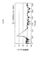
- FIG. 6 is a graph showing a spectrum obtained by using Hilbert transform.
- the frequency spectrum of FIG. 5 is obtained by converting the damped vibraton pattern in FIG. 4 by using Fourier transform. It is found from a peak value that a resonance frequency of the sample S is 787.7 Hz which is about the same as a resonance frequency of 780 Hz that is obtained by a method of scanning a frequency (with a minimum resolution of 10 Hz). It is found from a gradient of the graph in FIG. 6 that a Q value is 552.2.
- the resonance frequency obtained by using the inspecting method according to the present embodiment is the same as that in case using conventional measuring method from Embodiment 1, it is found that the inspection method works. Also, the conventional measuring method obtained the Q value from a Full Width at Half Maximum (FWHM) of a resonance curve. If the Q value is high, since the number of measurement occasions is so small that reliability of measured values is low, the conventional measuring method doesn't work sometimes. However, the inspection method according to the present embodiment may works even in case that the Q value is high as in Embodiment 1.
- FWHM Full Width at Half Maximum
- FIGS. 7 , 8, 9A , 9B , and 9C Results of Embodiment 2 are shown in FIGS. 7 , 8, 9A , 9B , and 9C .
- FIG. 7 is a graph showing an damped vibraton pattern.
- FIG. 8 is a graph showing an example of a frequency spectrum.
- FIGS. 9A through 9C are graphs showing a spectrum obtained by using Hilbert transform.
- FIGS. 9A through 9C are graphs showing spectrums obtained by converting each of the frequencies of FIG. 8 by using Hilbert transform in order from least to greatest.
- the three resonance frequencies are 9030 Hz, 13200 Hz, and 22000 Hz.
- a Q value is 54.5 in the case of the resonance frequency of 9030 Hz, 71.1 in the case of the resonance frequency of 13200 Hz, and 207.8 in the case of the resonance frequency of 22000 Hz.
- the fishbone acoustic sensor which is the sample S in Embodiment 2, is a microstructure having a complex structure in which a portion for receiving an input sound wave, a resonance portion that is supported with a cantilever, and a central line portion for connecting the portion for receiving the input sound wave to the resonance portion can move.
- Embodiment 2 it is found from the results of Embodiment 2 that although the microstructure has the complex structure, the measuring method according to the present invention works.
- the conventional measuring method may not work or suffer a low degree of measurement precision due to the influence of vibration of a portion on other portions if the microstructure has a complex structure.
- Embodiment 2 can work, and can also identify a portion having defects since a natural frequency of each portion may be found as a resonance frequency.
- the present invention can be used as a device for inspecting a microstructure including a moving portion.
Abstract
A microstructure inspecting device 10 which measures a damping characteristic value of a moving portion of a microstructure includes a pressure wave generating device 1 and a pulse generating device 2 which apply an impact to the moving portion without directly contacting the microstructure, and a vibrometer 4 which measures a displacement of the moving portion for a predetermined period of time after the start of free vibration of the moving portion without contacting the moving portion. The pressure wave generating device 1 is a sound wave generating element of thermal excitation type, a piezoelectric sound wave generating element, or an electromagnetic vibration element, and is driven by a pulse signal of the pulse generating device 2. The pressure wave generating device 1 using the sound wave generating element of thermal excitation type may include a thermally conductive substrate, a heat-insulating layer formed of nano-crystal silicon in one principal surface of the substrate, an insulating layer formed on the heat-insulating layer, and a conductive layer formed on the insulating layer and emitting heat when being supplied with current containing alternating current components.
Description
- The present invention relates to a device and method for inspecting a microstructure including a moving portion.
- Recently, microstructure devices, for example, various sensors using MEMS(Micro Electro Mechanical Systems), have been used in various fields including automobile and medical technology. As electronic devices have been made small and light and have high-level functions, the development of MEMS has also been promoted. Since MEMS are micro-fabricated systems, there is a demand for an appropriate method of inspecting the MEMS.
- Examples of a method of measuring mechanical characteristics, such as an attenuation factor (ζ), a Q value, a natural frequency (f0), and a loss factor (τ), of a microstructure include a method of obtaining a decay curve by using an impulse hammer, and a method of obtaining a resonance frequency by intentionally scanning an excitation frequency of a structure and thus obtaining an attenuation factor from a FWHM(Full Width at Half Maximum) of a resonance curve.
-
Patent Document 1 orPatent Document 2 discloses a method of causing a test sound wave to be output from a speaker to a moving portion of a sensor to move the moving portion, and thus inspecting electrical characteristics of a microstructure by using a probe.Patent Document 3 discloses a method of detecting a change in the resistance value of an acceleration sensor formed on a wafer by blowing air and thus determining the property of the acceleration sensor. - Also,
Patent Document 4 discloses a method of outputting an ultrasonic wave to a moving portion to induce slow dynamics on an object, and measuring a physical change. Also,Patent Document 5 discloses a method of intermittently generating a longitudinal wave by using a sound wave generating element of thermal excitation type, and thus detecting a distance to an object and an orientation where the object is located. Also,Patent Document 6 discloses a method of causing a PZT (lead zirconate titanate) ultrasonic wave transforming device to directly contact a microstructure, and thus measuring a dynamic response. - (Patent Document 1) Japanese Laid-Open Patent Publication No.
2007-108157 - (Patent Document 2) International Publication No.
2006/093232 - (Patent Document 3) Japanese Laid-Open Patent Publication No.
Hei 5-34371 - (Patent Document 4) Japanese Laid-Open Patent Publication No.
2004-523768 - (Patent Document 5) Japanese Laid-Open Patent Publication No.
2006-220637 - (Patent Document 6) Specification of
U.S. Patent No. 6595058 - The method using the impulse hammer indirectly moves the moving portion by passing through a support member of the microstructure and a support unit of the moving portion of the microstructure, and the like. Accordingly, since the impact time or intensity of impact to be applied to the moving portion cannot be precisely controlled, the degree of measurement precision of the decay curve is not high. Also, with respect to a DUT (die under tester: chip-state sample) having a low Q value, since an impact time and a decay time are almost the same, damping characteristics or the Q value cannot be measured. Also, the method disclosed in the
Patent Document 6 cannot directly excite the moving portion of the microstructure. Accordingly, vibration of a package (PKG) or a support case body overlaps with a signal line or reverberation of an impact source overlaps, thereby resulting in a decrease in the degree of measurement precision. - With respect to a DUT having a low Q value, although the method of applying a pressure to the moving portion of the sensor with a sound wave without using the impulse hammer can directly excite the moving portion of the microstructure to enable measurement, there exists the influence of reverberation of a speaker of a sound source. With respect to a DUT having a high Q value, the method of scanning the frequency is difficult to have a sufficient number of measurement points for FWHM.
- Since electrical characteristics of the microstructure are inspected by using the impulse hammer, the microstructure cannot be directly excited, and thus the microstructure has been excited in the form of a package (PKG). Accordingly, since defective products can be detected only in a final step of a manufacturing process, even though defects occur in the middle of the manufacturing process, the manufacturing process proceeds to the final step, thereby leading waste of time and money. Also, defect analysis and solution on defects is delayed, thereby reducing efficiency.
- The present invention is proposed considering the aforementioned state of art. According to the present invention a microstructure inspecting device and method capable of precisely and reproducibly controlling impact time and intensity and performing measurement with a high degree of precision may be provided.
- To solve the problems, according to an embodiment of the present invention, there is provided a microstructure inspecting device which measures a damping characteristic value of a moving portion of a microstructure, the microstructure inspecting device including an impact applying unit which applies an impact to the moving portion by using a pressure wave generation device that does not directly contact the microstructure; and a measuring unit which measures a displacement of the moving portion for a predetermined period of time after the start of free vibration of the moving portion, without contacting the moving portion.
- Preferably, the impact applying unit may include a sound wave generating element of thermal excitation type, and a driving unit which inputs a pulse signal to the sound wave generating element.
- Preferably, the sound wave generating element of thermal excitation type may include a thermally conductive substrate; a heat-insulating layer formed of nano-crystal silicon in one principal surface of the substrate; an insulating layer formed on the heat-insulating layer; and a conductive layer formed on the insulating layer and emitting heat when being supplied with current containing alternating current components.
- To solve the problems, according to another embodiment of the present invention, there is provided a microstructure inspecting method including: applying an impact to a moving portion of a microstructure by using a pressure wave generating device that does not directly contact the microstructure; causing the moving portion to freely vibrate; and measuring a displacement of the moving portion during a predetermined period of time after the start of the free vibration of the moving portion, without contacting the moving portion.
- Preferably, the pressure wave generating device may be a sound wave generating element of thermal excitation type.
- Preferably, the sound wave generating element of thermal excitation type may include a thermally conductive substrate; a heat-insulating layer formed of nano-crystal silicon in one principal surface of the substrate; an insulating layer formed on the heat-insulating layer; and a conductive layer formed on the insulating layer and emitting heat when being supplied with current containing alternating current components.
- Preferably, the microstructure inspecting method may further include calculating a Q value of the microstructure from the displacement of the moving portion measured in the measuring step; and determining that the microstructure is normal when the Q value is within a predetermined range, and determining that the microstructure is defective when the Q value is not within the predetermined range.
- Preferably, the microstructure inspecting method may further include feeding back the Q value calculated in the calculating step, and a determined result in the determining step to a control device that sets a manufacturing condition of a manufacturing device for manufacturing the microstructure.
- According to the microstructure inspecting device of the present invention, since impact time or intensity can be precisely and reproducibly controlled, the degree of measurement precision of vibration damping characteristics of a microstructure is improved.
-
-
FIG. 1 is a block diagram showing an example of a configuration of a microstructure inspecting device according to an embodiment of the present invention. -
FIG. 2A is a plan view of a pressure wave generating device according to the embodiment of the present invention. -
FIG. 2B is a cross-sectional view of the pressure wave generating device according to the embodiment of the present invention. -
FIG. 3 is a block diagram showing an example of a configuration of the manufacturing system including a microstructure inspecting device according to the embodiment of the present invention and a semiconductor manufacturing device. -
FIG. 4 is a graph showing an damped vibraton pattern of a first embodiment. -
FIG. 5 is a graph showing an example of a frequency spectrum in the first embodiment. -
FIG. 6 is a graph showing a spectrum obtained by Hilbert transform in the first embodiment. -
FIG. 7 is a graph showing an damped vibraton pattern of a second embodiment. - FIG. 8 is a graph showing an example of a frequency spectrum in the second embodiment.
-
FIG. 9A is a first graph showing a spectrum obtained by Hilbert transform in the second embodiment. -
FIG. 9B is a second graph showing a spectrum obtained by Hilbert transform in the second embodiment. -
FIG. 9C is a third graph showing a spectrum obtained by Hilbert transform in the second embodiment. - Herein below, embodiments of the present invention will be explained in detail with reference to the drawings. Also, the same or corresponding elements in the drawings are denoted by the same reference numerals, and a repeated explanation thereof will not be given.
FIG. 1 is a block diagram showing an example of a configuration of a microstructure inspecting device according to an embodiment of the present invention.FIG. 2A is a plan view showing connection of a driving circuit of a pressurewave generating device 1 shown inFIG. 1 .FIG. 2B is a cross-sectional view taken along line X-X ofFIG. 2A . - As shown in
FIG. 1 , amicrostructure inspecting device 10 includes the pressurewave generating device 1, apulse generating device 2, an amplifyingunit 3, avibrometer 4, a calculatingunit 5, asupport unit 6, achuck 7, and an inspectingstage 8. The pressurewave generating device 1 is supported by thesupport unit 6 and is installed on the inspectingstage 8. A sample S is placed to face a surface of the pressurewave generating device 1 on which a pressure wave is generated, and a wafer W having the sample S is supported by thechuck 7. - The
microstructure inspecting device 10 according to the present embodiment used the pressurewave generating device 1 in order to excite the sample S. A sound wave generating element of thermal excitation type is used in order to generate a pressure wave, and uses a longitudinal wave, which is generated by heating and cooling air by using a heater, as a sound wave. Accordingly, impact time or intensity can be precisely and reproducibly controlled by using the heater. Since a speaker including a vibration plate having elasticity and mass is not used, there is no risk of reverberation. Also, if the mass of the vibration plate is negligible and a moving portion can vibrate without contacting the sample S, a piezoelectric sound wave generating element may be used in order to generate a pressure wave. Also, by forming a coil around a microstructure, an impact may be directly applied to the sample S by exciting the coil through electromagnetic induction. - As shown in
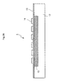
FIGS. 2A and2B , the pressurewave generating device 1 includes asubstrate 12, a heat-insulatinglayer 13, aheating element 14, and an insulatinglayer 15. A drivingcircuit 16 is electrically connected to both ends of theheating element 14. Thesubstrate 12 is formed of bulk silicon or the like. The heat-insulatinglayer 13 formed of porous nano-crystal silicon (hereinafter, referred to as nc-Si) is formed in one principal surface of thesubstrate 12. The insulatinglayer 15 is formed in the surface of thesubstrate 12, in which the heat-insulatinglayer 13 is formed, to contact the heat-insulatinglayer 13. The insulatinglayer 15 is formed of a thin film of an insulating material such as silicon nitride (Si3N4), silicon dioxide (SiO2), aluminum oxide (Al2O3), or the like. Theheating element 14 having a heater pattern is formed of a thin film of a electrically conductive metal, for example, tungsten (W), platinum (Pt), or gold (Au), to contact a top of the insulatinglayer 15. - The driving
circuit 16 applies an intermittent pulse voltage, or an alternating current voltage, at a predetermined frequency ω to both ends of theheating element 14. The thickness of the heat-insulatinglayer 13, with respect to alternating current components of the voltage applied to theheating element 14, is about the same as a thermal diffusion length determined by the thermal conductivity and heat capacity per unit volume of the heat-insulatinglayer 13. Accordingly, alternating current components of emitted heat to thesubstrate 12 side are insulated and direct current components of the emitted heat generated due to the heat capacity of theheating element 14 may efficiently diffuse to thesubstrate 12 having high thermal conductivity. If the heat-insulatinglayer 13 is formed of nc-Si, although the thickness of the heat-insulatinglayer 13 may vary according to a frequency of a sound wave generated, the thickness of the heat-insulatinglayer 13 may range, for example, from about 5 µm to about 200 µm. - The thickness of the insulating
layer 15 is sufficiently less than the thermal diffusion length, and thus the alternating current components of the emitted heat of theheating element 14 are insulated in a thickness direction of the heat-insulatinglayer 13. The insulatinglayer 15 conducts heat in a surface direction. Since theheating element 14 is closely attached to the insulatinglayer 15, the insulatinglayer 15 operates to make the temperature of theheating element 14 uniform. Since the insulatinglayer 15 does not allow electricity to pass therethrough, the insulatinglayer 15 does not emit heat, and reduces local thermal stress of theheating element 14 by making the temperature of theheating element 14 uniform. Accordingly, even with a voltage leading to breaking of wire which a conventional pressure wave generating device may encounter, theheating element 14 rarely undergoes deformation or breaking of wire. As a result, it is possible to increase the sound pressure of a sound wave generated by the pressurewave generating device 1. - It is preferable that the insulating
layer 15 has high thermal conductivity in an in-plane direction, and does not absorb heat in a thickness direction. Accordingly, the insulatinglayer 15 may be thinly formed of a material having high thermal conductivity and low specific heat. The insulatinglayer 15 may be formed of a material, for example, magnesium oxide (MgO), diamond crystalline carbon (C), aluminum nitride (AIN), or silicon carbide SiC as well as the aforesaid silicon nitride (Si3N4), silicon dioxide (SiO2), or aluminum oxide (Al2O3). The thickness of the insulatinglayer 15 ranges, for example, about 50 nm to about 200 nm. - The
heating element 14 is not limited to a specific material if theheating element 14 is formed of a metal film. For example, theheating element 14 may be formed of a metal simple substance such as tungsten (W), molybdenum (Mo), iridium (Ir), gold (Au), aluminum (Al), nickel (Ni), titanium (Ti), and platinum (Pt), or a stacked structure thereof. Theheating element 14 may be formed by vacuum deposition, sputtering, or the like. Also, although it is preferable that the thickness of the metal film is as small as possible in order to reduce heat capacity, the thickness of the film may be selected from a range of 10 nm to 300 nm in order to have appropriate resistance. - Now, a process of forming the pressure
wave generating device 1 will be explained with reference toFIG. 2B . First, thesubstrate 12 of a silicon wafer is prepared, and an electrode layer formed of a thin film of, for example, aluminum, is formed on an inner surface by vacuum deposition or the like. Next, anodizing is performed by using a mixture solution of hydrofluoric acid (HF) and ethanol on a portion where the heat-insulatinglayer 13 is to be formed by using platinum (Pt) as a counter electrode. The heat-insulatinglayer 13 having a desired thickness and grain size and formed of porous nc-Si is formed by controlling a component ratio of the solution, current density, and a processing time to have predetermined values. The insulatinglayer 15 is formed on the surface of thesubstrate 12 in which the heat-insulatinglayer 13 is formed. Non-doped silicate glass (NSG) or the like is deposited on thesubstrate 12 by using, for example, plasma CVD, to form the insulatinglayer 15. - For example, a stencil mask S patterned to have the shape of the
heating element 14 is held on the insulatinglayer 15, and theheating element 14 is formed to have a predetermined pattern on the insulatinglayer 15 by gold (Au) sputtering. Next, an electrode or the like for connecting the drivingcircuit 16 to theheating element 14 is formed, and the electrode layer formed on the inner surface undergoes removal, polishing, or the like if necessary. - Referring to
FIGS. 1 ,2A , and2B again, a microstructure inspecting order in the present embodiment of the present invention will be explained. A voltage transmitted from thepulse generating device 2 is amplified to become a plurality of pulse voltages or a pulse voltage having a desired time width by the amplifyingunit 3, and is applied in burst shape to theheating element 14 of the pressurewave generating device 1. Theheating element 14 generates a pressure wave of an impulse by heating and cooling an ambient air layer, and radiates the pressure wave to the sample S to excite the sample S. Due to the excitation, a moving portion of the sample S starts damped vibraton. The vibration of the moving portion is measured by using thevibrometer 4, for example, a non-contact type laser vibrometer. - Since the pressure
wave generating device 1 can precisely and reproducibly control impact time or intensity, a sound pressure enough to measure can be obtained, thereby increasing the degree of measurement precision. Also, the pressurewave generating device 1 does not have the influence of reverberation of an impulse source when the pressure is applied, thereby not having the influence of noise. Also, since the pressurewave generating device 1 can directly excite the microstructure so that the microstructure does not have to contact the sample S to measure the amount of displacement, the pressurewave generating device 1 doesn't affect the damped vibraton of the moving portion. - The amount of displacement measured by the
vibrometer 4 may be calculated as an damped vibraton pattern by the calculatingunit 5 to obtain a resonance frequency or a Q value. If the obtained value is not within a predetermined numerical range, it is determined that there is abnormality and thus good products and defective products can be distinguished. - A Q value, which is a dimensionless number primarily indicating the state of vibration, is related to loss of energy due to absorption by a medium, in the propagation of elastic waves. In vibration, the Q value is energy obtained by dividing energy stored in a system during one period by energy dissipated in the system, where a larger Q value indicates greater vibration stability. If the Q value is high, it means that the state of vibration is stable, and a startup time is long and the distribution of vibration energy is high. A resonance frequency is obtained from a value obtained by converting a vibration pattern into a frequency spectrum by using Fourier transform. Also, a Q value is obtained from a gradient of a spectrum graph that is obtained by converting the vibration pattern by using Hilbert transform. For example, if an object to be inspected is a MEMS, it can be determined whether a spring constant of a moving portion of the MEMS is normal or not by using a resonance frequency. Also, structural defects in a pressure sensor, a gyro sensor, or the like can be detected by using a Q value.
-
FIG. 3 is a block diagram showing a configuration of a manufacturing system including a semiconductor manufacturing device and themicrostructure inspecting device 10 according to the embodiment of the present invention. A representative semiconductor manufacturing process includes a pre-process and a post-process, wherein the pre-process includes a circuit design, a patterns design, a photomask making, a wafer manufacturing, and elements formation, and the post-process includes assembly, final inspection and marking. The semiconductor manufacturing device shown inFIG. 3 is a photolithography/etching processing device 20 of a microstructure (MEMS) (hereinafter, referred to as a processing device 20) and is used in the wafer manufacturing process. - The
microstructure inspecting device 10 is the same as that shown inFIG. 1 and an explanation thereof will be omitted. The calculatingunit 5 of themicrostructure inspecting device 10 is connected to acontrol unit 40 of theprocessing device 20. Thecontrol unit 40 includes a calculation processing device and a ROM that stores a processing program and the like, and controls thewhole processing device 20 and individual systems constituting theprocessing device 20. - The
processing device 20 includes acassette station 21 and aprocessing station 22. Thecassette station 21 transfers wafers W, which are supplied from the outside in the unit of a wafer cassette, fromcassettes 23 to theprocessing device 20, or transfers the wafers W having been processed from theprocessing device 20 to thecassettes 23. Theprocessing station 22 includes a plurality of processing units, and performs photolithography/etching while sequentially moving the wafers W to each of the processing units. - A
cassette holding stage 24 is formed in thecassette station 21, and one of thecassettes 23 in which a wafer W to be processed is stored is supplied from the outside. Also, in thecassette holding stage 24, a wafer W having been processed is stored in acassette 23 to be transferred out. Transfer of a wafer W on thecassette holding stage 24 is performed by astation transfer mechanism 25. Thestation transfer mechanism 25 can move horizontally (in a direction marked by a solid arrow) and vertically (in a direction perpendicular to the ground) so as to access the plurality ofcassettes 23 placed on thecassette holding stage 24. Also, thestation transfer mechanism 25 can rotate (in a direction marked by a dotted arrow) so as to transfer the wafer W from theprocessing station 22 to thecassette holding stage 24. - A plurality of photolithography/etching processing units (processing
units 26 through 28), aunit transfer mechanism 29, and a temporarily-holdingstage 30 are formed in theprocessing station 22. A resist pattern is formed in theprocessing unit 26. Etching is performed in theprocessing unit 27. A film is formed and the resist is removed in theprocessing unit 28. - A wafer W transferred to the
processing station 22 is placed on the temporarily-holdingstage 30, and theunit transfer mechanism 29 starts to act as a transfer mechanism instead of thestation transfer mechanism 25. Due to theunit transfer mechanism 29, the wafer W is sequentially transferred in the order of theprocessing unit 26, theprocessing unit 27, and theprocessing unit 28 so that photolithography/etching is performed on the wafer W. The wafer W on which the processing has been completed is placed on the temporarily-holdingstage 30 again, and is transferred from theprocessing station 22 by thestation transfer mechanism 25. Theunit transfer mechanism 29 can move horizontally and vertically, and rotate, like thestation transfer mechanism 25. - A resist pattern is formed in the
processing unit 26. The wafer W transferred to theprocessing unit 26 is covered with a photomask due to a resist spread. The wafer W covered with the photomask is exposed and developed, to form a resist having a desired shape (pattern) on the wafer W. The resist is cured by heating to be adhered to the wafer W. If exposure or development is insufficient, the resist may be deformed to have a pattern other than the desired pattern. - Etching is performed in the
processing unit 27. Although there are wet etching and dry etching, wet etching will be explained herein. The wafer W is immersed in an etching solution such as hydrogen fluoride or the like, and a portion of the wafer W not covered with the resist is etched. A portion of the wafer W protected by the resist is not etched and thus the same shape as the shape of the resist is bulgingly formed on the wafer W. An etching state varies according to the temperature or time of the etching solution, and also, as an etching depth increases, etching may occur even in a portion directly under the resist. - A film is formed and the resist is removed in the
processing unit 28. In the formation of the film, a layer formed of a metal or an oxide film is formed on the wafer W by using vacuum deposition, sputtering, or the like. Next, the resist is completely removed by using a resist solvent or the like. Since a film formed on the resist is also removed during the removal of the resist, a desired pattern can be added to the upper surface of the wafer W. - In a microstructure having a complex structure, after processing in the
processing unit 28, photolithography/etching is repeatedly performed in processing units(not shown) 26a, 27a, 28a through 26n, 27n, and 28n. Also, the microstructure is manufactured by machanoelectric conversion device formation, wire formation, and the like as well as performing photolithography/etching. - The wafer W in which the microstructure is formed is engaged on the
microstructure inspecting device 10. The microstructure, which is a sample S, is located facing an output portion of the pressurewave generating device 1, and the wafer W is supported by thechuck 7. A voltage transmitted from thepulse generating device 2 is amplified to a plurality of pulse voltages or a pulse voltage having a desired time width by the amplifyingunit 3, and is applied in a burst shape to theheating element 14 of the pressurewave generating device 1. Theheating element 14 generates a pressure wave of an impulse by heating and cooling an ambient air layer, and radiates the pressure wave to the sample S to excite the sample S. Since the sample S is directly excited, there is no influence of reverberation or noise. Also, since the impact time or intensity of the pressure wave is precisely controlled, reproducibility is high. A moving portion of the sample S starts damped vibraton due to the excitation. The vibration of the moving portion is measured by using thevibrometer 4, for example, a laser Doppler vibrometer. - Also, measuring of displacement of the sample S by the
vibrometer 4 is performed for a predetermined period of time after the start of free vibration of the sample S. That is, the pressure wave generating device 1 (speaker) radiates the pressure wave to the sample S (the moving portion) to enable the sample S to vibrate. Next, the pressurewave generating device 1 stops the radiation of the pressure wave to the sample S to enable the sample S to freely vibrate. And, thevibrometer 4 measures the displacement of the sample S while the sample S is freely vibrating. Here, free vibration refers to vibration of the moving portion in a state where reverberation of the speaker or other peripheral equipment is zero or negligible. While the sample S is freely vibrating, external influence is zero. Accordingly, while the sample S is freely vibrating, only damping characteristics of the sample S can be purely measured. In particular, since a nano-crystal silicon speaker can reduce reverberation, the nano-crystal silicon speaker is suitable for such a measurement system. - A measured damped vibraton pattern is numerically processed by the calculating
unit 5 to calculate a resonance frequency and a Q value, and thus it is determined whether the microstructure is good or bad. If the resonance frequency exceeds a designated numerical range, it may be found that a spring constant of the moving portion of the microstructure is abnormal. If the Q value exceeds a preset range, it is found that the structure of a sensor is abnormal. For example, damage to the microstructure may be occurred or film thickness may be abnormal. - Analysis of causes of defects is performed based on abnormality in the resonance frequency or the Q value. If the resonance frequency is low, it is possible that the moving portion is small or the support unit is thin due to, for example, over-etching. Also, if the Q value is low, that is, if vibration is immediately reduced, it is possible that the microstructure is damaged. It is possible that the resist formation is not performed well, the wafer W is not sufficiently protected, the wafer W is excessively etched, and thus the resist fails to have a desired shape. Alternatively, since a film is not formed well, thick or thin film formation or the like may occur.
- Information about the measured resonance frequency and the Q value of the microstructure is fed back from the calculating
unit 5 to thecontrol unit 40. If there is a feedback of information indicating that the value is out of a preset desired numerical range that means the microstructure is in a good state, conditions for predicted questions and corresponding solutions are set according to a state of abnormal value, so that a control instruction may be output to a corresponding system from thecontrol unit 40. Also, a program of thecontrol unit 40 may be previously set so that a buzzer sound or flash light is occurred from an external device connected to thecontrol unit 40 to indicate abnormality. If both the resonance frequency and the Q value are abnormal, it is possible to set theprocessing station 22 to temporarily stops. - For example, if the resonance frequency is abnormal, it is possible that etching results are not in accordance with design. Accordingly, a control instruction is output from the
control unit 40 to theprocessing unit 27 to suitably change etching conditions or the like. If the Q value is much different from a desired value, it is possible that damage to the microstructure is occurred. It is possible that the resist is not formed to have a desired shape and thus the resist fails to protect the wafer W during etching. A control instruction is transmitted from thecontrol unit 40 to theprocessing unit 26 where the resist is formed, to suitably change conditions for photolithography, etc. In case that abnormality in the Q value of the microstructure manufactured after conditions in theprocessing unit 26 are changed occurs, it is highly possible that not in the formation of the resist but the formation of the film is abnormal. A control instruction is transmitted from thecontrol unit 40 to theprocessing unit 28, to suitably change conditions for film formation. - Also, even when measurement results indicate good products, the trend of the manufacturing state may be kept track of by accumulating fed-back measurement data and repeatedly reflecting the measurement data. Also, when the measurement results indicate good products, adjusting various conditions by automatic control is helpful in performing the manufacturing process while maintaining product quality constant.
- The wafer W of which measurement has been completed is transferred to a next process at the same time as the
control unit 40 feeds back the measurement results. Accordingly, since processing conditions of the wafer W on which the microstructure is formed can be adjusted by automatic control from now on, generation of defective products can be prevented. Also, since the microstructure of which the resonance frequency and the Q value was abnormal is checked, the microstructure can be discarded after cutting off of a chip. Accordingly, defective products can be removed without bringing the manufacturing process to a final step. - As described above, since the microstructure inspecting method according to the present invention can precisely and reproducibly control impact time or intensity, the degree of measurement precision of vibration damping characteristics of a microstructure is improved. Also, it is helpful in performing the manufacturing process while maintaining product quality constant that measurement results are fed back to the control device. Also, since an inspection is not limited to a final step of the manufacturing process, defective products are reduced and efficient manufacturing can be achieved.
- The
microstructure inspecting device 10 according to the present embodiment used the pressurewave generating device 1 in order to excite the sample S. Although the sound wave generating element of thermal excitation type was used in order to generate the pressure wave, a coil may be formed on the microstructure and an impact may be directly applied to the sample S by exciting the coil due to electron induction. - Also, there may be changes or modifications in the configurations of the pressure
wave generating device 1, or themicrostructure inspecting device 10 using the pressurewave generating device 1 without being limited to the aforesaid embodiments, or there may be combinations of the devices. For example, selections or combinations of devices are not limited to those shown inFIG. 3 , and in terms of hardware, any of various shapes, patterns, sizes, etc. may be arbitrarily selected, and in terms of software, any of program setting, particularly, setting of desired numerical ranges for good products, may be arbitrarily selected, according to objects to be measured. A process in which the inspection is to be perfomed in a manufacturing step is not limited to the embodiments and may be arbitrarily selected. - Next, as an example of an embodiment of the present invention, a measurement was performed in case that the sample S, which was an object to be inspected, was a pendulum of an acceleration sensor or a fishbone acoustic sensor.
Embodiment 1 shows a case using the pendulum of the acceleration sensor, andEmbodiment 2 shows a case using the fishbone acoustic sensor. - Results of
Embodiment 1 are shown inFIGS. 4 through 6 .FIG. 4 is a graph showing an damped vibraton pattern.FIG. 5 is a graph showing an example of a frequency spectrum.FIG. 6 is a graph showing a spectrum obtained by using Hilbert transform. - The frequency spectrum of
FIG. 5 is obtained by converting the damped vibraton pattern inFIG. 4 by using Fourier transform. It is found from a peak value that a resonance frequency of the sample S is 787.7 Hz which is about the same as a resonance frequency of 780 Hz that is obtained by a method of scanning a frequency (with a minimum resolution of 10 Hz). It is found from a gradient of the graph inFIG. 6 that a Q value is 552.2. - Since the resonance frequency obtained by using the inspecting method according to the present embodiment is the same as that in case using conventional measuring method from
Embodiment 1, it is found that the inspection method works. Also, the conventional measuring method obtained the Q value from a Full Width at Half Maximum (FWHM) of a resonance curve. If the Q value is high, since the number of measurement occasions is so small that reliability of measured values is low, the conventional measuring method doesn't work sometimes. However, the inspection method according to the present embodiment may works even in case that the Q value is high as inEmbodiment 1. - Results of
Embodiment 2 are shown inFIGS. 7 , 8,9A ,9B , and9C .FIG. 7 is a graph showing an damped vibraton pattern. FIG. 8 is a graph showing an example of a frequency spectrum.FIGS. 9A through 9C are graphs showing a spectrum obtained by using Hilbert transform. - From the number of peak values in the frequency spectrum of FIG. 8, which is obtained by converting the damped vibraton pattern of
FIG. 7 by using Fourier transform, it is found that there are 3 resonance frequencies.FIGS. 9A through 9C are graphs showing spectrums obtained by converting each of the frequencies of FIG. 8 by using Hilbert transform in order from least to greatest. As shown in FIG. 8, the three resonance frequencies are 9030 Hz, 13200 Hz, and 22000 Hz. Also, as shown inFIGS. 9A through 9C , a Q value is 54.5 in the case of the resonance frequency of 9030 Hz, 71.1 in the case of the resonance frequency of 13200 Hz, and 207.8 in the case of the resonance frequency of 22000 Hz. - The fishbone acoustic sensor, which is the sample S in
Embodiment 2, is a microstructure having a complex structure in which a portion for receiving an input sound wave, a resonance portion that is supported with a cantilever, and a central line portion for connecting the portion for receiving the input sound wave to the resonance portion can move. - It is found from the results of
Embodiment 2 that although the microstructure has the complex structure, the measuring method according to the present invention works. The conventional measuring method may not work or suffer a low degree of measurement precision due to the influence of vibration of a portion on other portions if the microstructure has a complex structure.Embodiment 2 can work, and can also identify a portion having defects since a natural frequency of each portion may be found as a resonance frequency. - The present application is based on Japanese Patent Application No.
2007-304597 filed on November 26, 2007 2007-304597 - The present invention can be used as a device for inspecting a microstructure including a moving portion.
Claims (8)
- A microstructure inspecting device which measures a damping characteristic value of a moving portion of a microstructure, the microstructure inspecting device comprising:an impact applying unit which applies an impact to the moving portion by using a pressure wave generation device that does not directly contact the microstructure; anda measuring unit which measures a displacement of the moving portion for a predetermined period of time after the start of free vibration of the moving portion, without contacting the moving portion.
- The microstructure inspecting device of claim 1, wherein the impact applying unit comprises a sound wave generating element of thermal excitation type, and a driving unit which inputs a pulse signal to the sound wave generating element.
- The microstructure inspecting device of claim 2, wherein the sound wave generating element of thermal excitation type comprises:a thermally conductive substrate;a heat-insulating layer formed of nano-crystal silicon in one principal surface of the substrate;an insulating layer formed on the heat-insulating layer; anda conductive layer formed on the insulating layer and emitting heat when being supplied with current containing alternating current components.
- A microstructure inspecting method comprising:applying an impact to a moving portion of a microstructure by using a pressure wave generating device that does not directly contact the microstructure;causing the moving portion to freely vibrate; andmeasuring a displacement of the moving portion during a predetermined period of time after the start of the free vibration of the moving portion, without contacting the moving portion.
- The microstructure inspecting method of claim 4, wherein the pressure wave generating device is a sound wave generating element of thermal excitation type.
- The microstructure inspecting method of claim 5, wherein the sound wave generating element of thermal excitation type comprises:a thermally conductive substrate;a heat-insulating layer formed of nano-crystal silicon in one principal surface of the substrate;an insulating layer formed on the heat-insulating layer; anda conductive layer formed on the insulating layer and emitting heat when being supplied with current containing alternating current components.
- The microstructure inspecting method of any one of claims 4, further comprising:calculating a Q value of the microstructure from the displacement of the moving portion measured in the measuring step; anddetermining that the microstructure is normal when the Q value is within a predetermined range, and determining that the microstructure is defective when the Q value is not within the predetermined range.
- The microstructure inspecting method of claim 7, further comprising:feeding back the Q value calculated in the calculating step, and a determined result in the determining step to a control device that sets a manufacturing condition of a manufacturing device for manufacturing the microstructure.
Applications Claiming Priority (2)
| Application Number | Priority Date | Filing Date | Title |
|---|---|---|---|
| JP2007304597 | 2007-11-26 | ||
| PCT/JP2008/071471 WO2009069670A1 (en) | 2007-11-26 | 2008-11-26 | Microstructure inspecting device, and microstructure inspecting method |
Publications (1)
| Publication Number | Publication Date |
|---|---|
| EP2221614A1 true EP2221614A1 (en) | 2010-08-25 |
Family
ID=40678563
Family Applications (1)
| Application Number | Title | Priority Date | Filing Date |
|---|---|---|---|
| EP08854451A Withdrawn EP2221614A1 (en) | 2007-11-26 | 2008-11-26 | Microstructure inspecting device, and microstructure inspecting method |
Country Status (6)
| Country | Link |
|---|---|
| US (1) | US8333114B2 (en) |
| EP (1) | EP2221614A1 (en) |
| JP (1) | JPWO2009069670A1 (en) |
| KR (1) | KR20100095560A (en) |
| CN (2) | CN102654481A (en) |
| WO (1) | WO2009069670A1 (en) |
Cited By (9)
| Publication number | Priority date | Publication date | Assignee | Title |
|---|---|---|---|---|
| US11476145B2 (en) | 2018-11-20 | 2022-10-18 | Applied Materials, Inc. | Automatic ESC bias compensation when using pulsed DC bias |
| US11699572B2 (en) | 2019-01-22 | 2023-07-11 | Applied Materials, Inc. | Feedback loop for controlling a pulsed voltage waveform |
| US11791138B2 (en) | 2021-05-12 | 2023-10-17 | Applied Materials, Inc. | Automatic electrostatic chuck bias compensation during plasma processing |
| US11798790B2 (en) | 2020-11-16 | 2023-10-24 | Applied Materials, Inc. | Apparatus and methods for controlling ion energy distribution |
| US11848176B2 (en) | 2020-07-31 | 2023-12-19 | Applied Materials, Inc. | Plasma processing using pulsed-voltage and radio-frequency power |
| US11887813B2 (en) | 2021-06-23 | 2024-01-30 | Applied Materials, Inc. | Pulsed voltage source for plasma processing |
| US11901157B2 (en) | 2020-11-16 | 2024-02-13 | Applied Materials, Inc. | Apparatus and methods for controlling ion energy distribution |
| US11948780B2 (en) | 2021-05-12 | 2024-04-02 | Applied Materials, Inc. | Automatic electrostatic chuck bias compensation during plasma processing |
| US11967483B2 (en) | 2021-06-02 | 2024-04-23 | Applied Materials, Inc. | Plasma excitation with ion energy control |
Families Citing this family (20)
| Publication number | Priority date | Publication date | Assignee | Title |
|---|---|---|---|---|
| US8676543B2 (en) * | 2009-06-23 | 2014-03-18 | Exxonmobil Research And Engineering Company | Determining the resonance parameters for mechanical oscillators |
| JP5617210B2 (en) * | 2009-09-14 | 2014-11-05 | デクセリアルズ株式会社 | Light-reflective anisotropic conductive adhesive and light-emitting device |
| US8245748B2 (en) * | 2010-07-14 | 2012-08-21 | Dukane Corporation | Vibration welding system |
| MX2013003404A (en) | 2010-09-24 | 2013-08-29 | Rassini Frenos Sa De Cv | Method of measuring damping using optical imaging technique. |
| KR101220373B1 (en) | 2010-09-30 | 2013-01-09 | 기아자동차주식회사 | System and method for motor control of hybrid vehicle |
| US9897518B2 (en) | 2012-04-23 | 2018-02-20 | Rassini Frenos, S.A. De C.V. | Method and apparatus for measuring damping in a workpiece |
| WO2013183313A1 (en) * | 2012-06-06 | 2013-12-12 | 日本電気株式会社 | Structure analysis device and structure analysis method |
| WO2015111603A1 (en) * | 2014-01-24 | 2015-07-30 | 国立大学法人東京大学 | Ultrasound generation element |
| US10024825B2 (en) * | 2014-12-26 | 2018-07-17 | Axcelis Technologies, Inc. | Wafer clamp detection based on vibration or acoustic characteristic analysis |
| CN105352690B (en) * | 2015-11-26 | 2018-01-23 | 清华大学 | Vibration measurement method of the medicine equipment in magnetic field |
| US10134649B2 (en) | 2016-01-06 | 2018-11-20 | International Business Machines Corporation | Scanning acoustic microscope sensor array for chip-packaging interaction package reliability monitoring |
| WO2018235195A1 (en) * | 2017-06-21 | 2018-12-27 | 株式会社東芝 | Structure evaluation system and structure evaluation method |
| US10555412B2 (en) | 2018-05-10 | 2020-02-04 | Applied Materials, Inc. | Method of controlling ion energy distribution using a pulse generator with a current-return output stage |
| CN109668666A (en) * | 2019-01-21 | 2019-04-23 | 河南翔宇医疗设备股份有限公司 | It is a kind of for detecting the test equipment and method of extracorporeal shock energy density of wave |
| US11508554B2 (en) | 2019-01-24 | 2022-11-22 | Applied Materials, Inc. | High voltage filter assembly |
| US11495470B1 (en) | 2021-04-16 | 2022-11-08 | Applied Materials, Inc. | Method of enhancing etching selectivity using a pulsed plasma |
| US11810760B2 (en) | 2021-06-16 | 2023-11-07 | Applied Materials, Inc. | Apparatus and method of ion current compensation |
| US11776788B2 (en) | 2021-06-28 | 2023-10-03 | Applied Materials, Inc. | Pulsed voltage boost for substrate processing |
| US11476090B1 (en) | 2021-08-24 | 2022-10-18 | Applied Materials, Inc. | Voltage pulse time-domain multiplexing |
| US11694876B2 (en) | 2021-12-08 | 2023-07-04 | Applied Materials, Inc. | Apparatus and method for delivering a plurality of waveform signals during plasma processing |
Family Cites Families (20)
| Publication number | Priority date | Publication date | Assignee | Title |
|---|---|---|---|---|
| JPH04178538A (en) | 1990-11-14 | 1992-06-25 | Nippon Steel Corp | Method and apparatus for generating and detecting ultrasonic waves in sample |
| JPH0534371A (en) | 1991-07-31 | 1993-02-09 | Tokai Rika Co Ltd | Measuring apparatus for sensitivity of semiconductor acceleration sensor |
| JPH06118070A (en) | 1992-10-08 | 1994-04-28 | Iwatsu Electric Co Ltd | Exciting method and exciting device |
| US5398785A (en) * | 1993-01-11 | 1995-03-21 | Regeants Of The University Of California | Semiactive control apparatus for damping vibrations of a body |
| US5520052A (en) * | 1994-02-10 | 1996-05-28 | The United States Of America As Represented By The United States Department Of Energy | Method and apparatus for determining material structural integrity |
| SE518997C2 (en) | 2001-04-02 | 2002-12-17 | Impressonic Ab | Method and apparatus for detecting damage in materials or articles |
| US6595058B2 (en) * | 2001-06-19 | 2003-07-22 | Computed Ultrasound Global Inc. | Method and apparatus for determining dynamic response of microstructure by using pulsed broad bandwidth ultrasonic transducer as BAW hammer |
| US7872394B1 (en) * | 2001-12-13 | 2011-01-18 | Joseph E Ford | MEMS device with two axes comb drive actuators |
| US6907787B2 (en) * | 2003-04-30 | 2005-06-21 | Honeywell International Inc. | Surface acoustic wave pressure sensor with microstructure sensing elements |
| JP2005114376A (en) | 2003-10-02 | 2005-04-28 | Sonix Kk | Method and device for inspecting object using ultrasonic wave |
| EP1695063A1 (en) * | 2003-12-11 | 2006-08-30 | Eidgenössische Technische Hochschule Zürich | Device and method for measuring flexural damping of fibres |
| JP4387987B2 (en) * | 2004-06-11 | 2009-12-24 | 株式会社オクテック | Microstructure inspection apparatus, microstructure inspection method, and microstructure inspection program |
| CN1710388A (en) * | 2004-06-17 | 2005-12-21 | 史铁林 | 3-D measuring apparatus for dynamic property and reliability of microelectromechanic system |
| JP2006220637A (en) | 2004-07-27 | 2006-08-24 | Matsushita Electric Works Ltd | Sensor system |
| CN101133320A (en) | 2005-03-03 | 2008-02-27 | 东京毅力科创株式会社 | Minute structure inspection device, minute structure inspection method, and minute structure inspection program |
| JP4573794B2 (en) | 2005-03-31 | 2010-11-04 | 東京エレクトロン株式会社 | Probe card and microstructure inspection device |
| GB0513756D0 (en) | 2005-07-06 | 2005-08-10 | Univ Nottingham | Spatially resolved acoustic spectroscopy imaging |
| KR100763193B1 (en) * | 2005-10-13 | 2007-10-04 | 삼성전자주식회사 | System and Method for providing DRM license |
| JP5221864B2 (en) | 2005-10-26 | 2013-06-26 | パナソニック株式会社 | Pressure wave generator and manufacturing method thereof |
| JP4901280B2 (en) | 2006-04-18 | 2012-03-21 | 東京エレクトロン株式会社 | Sound acquisition device, sound calibration device, sound measurement device, and program. |
-
2008
- 2008-11-26 WO PCT/JP2008/071471 patent/WO2009069670A1/en active Application Filing
- 2008-11-26 JP JP2009543832A patent/JPWO2009069670A1/en active Pending
- 2008-11-26 CN CN2012100976382A patent/CN102654481A/en active Pending
- 2008-11-26 KR KR1020107012325A patent/KR20100095560A/en not_active Application Discontinuation
- 2008-11-26 CN CN200880117854A patent/CN101874203A/en active Pending
- 2008-11-26 US US12/744,873 patent/US8333114B2/en not_active Expired - Fee Related
- 2008-11-26 EP EP08854451A patent/EP2221614A1/en not_active Withdrawn
Non-Patent Citations (1)
| Title |
|---|
| See references of WO2009069670A1 * |
Cited By (9)
| Publication number | Priority date | Publication date | Assignee | Title |
|---|---|---|---|---|
| US11476145B2 (en) | 2018-11-20 | 2022-10-18 | Applied Materials, Inc. | Automatic ESC bias compensation when using pulsed DC bias |
| US11699572B2 (en) | 2019-01-22 | 2023-07-11 | Applied Materials, Inc. | Feedback loop for controlling a pulsed voltage waveform |
| US11848176B2 (en) | 2020-07-31 | 2023-12-19 | Applied Materials, Inc. | Plasma processing using pulsed-voltage and radio-frequency power |
| US11798790B2 (en) | 2020-11-16 | 2023-10-24 | Applied Materials, Inc. | Apparatus and methods for controlling ion energy distribution |
| US11901157B2 (en) | 2020-11-16 | 2024-02-13 | Applied Materials, Inc. | Apparatus and methods for controlling ion energy distribution |
| US11791138B2 (en) | 2021-05-12 | 2023-10-17 | Applied Materials, Inc. | Automatic electrostatic chuck bias compensation during plasma processing |
| US11948780B2 (en) | 2021-05-12 | 2024-04-02 | Applied Materials, Inc. | Automatic electrostatic chuck bias compensation during plasma processing |
| US11967483B2 (en) | 2021-06-02 | 2024-04-23 | Applied Materials, Inc. | Plasma excitation with ion energy control |
| US11887813B2 (en) | 2021-06-23 | 2024-01-30 | Applied Materials, Inc. | Pulsed voltage source for plasma processing |
Also Published As
| Publication number | Publication date |
|---|---|
| US20100307248A1 (en) | 2010-12-09 |
| KR20100095560A (en) | 2010-08-31 |
| US8333114B2 (en) | 2012-12-18 |
| CN101874203A (en) | 2010-10-27 |
| JPWO2009069670A1 (en) | 2011-04-14 |
| CN102654481A (en) | 2012-09-05 |
| WO2009069670A1 (en) | 2009-06-04 |
Similar Documents
| Publication | Publication Date | Title |
|---|---|---|
| US8333114B2 (en) | Microstructure inspecting device, and microstructure inspecting method | |
| JP4388614B2 (en) | Sensor for measuring the viscosity and density of a medium | |
| US7424827B2 (en) | Inspecting method of elastic body, inspecting apparatus thereof, and dimension predicting program thereof | |
| US6595058B2 (en) | Method and apparatus for determining dynamic response of microstructure by using pulsed broad bandwidth ultrasonic transducer as BAW hammer | |
| US9476861B2 (en) | Ultrasound diagnostic device and ultrasound probe | |
| EP3727708B1 (en) | Method for tuning a resonant frequency of a piezoelectric micromachined ultrasonic transducer | |
| JP2003149213A (en) | Ultrasonic inspecting apparatus, ultrasonic transducer, and inspecting apparatus | |
| EP1533611A1 (en) | Apparatus and method for measuring micro mass using oscillation circuit | |
| JP6183012B2 (en) | Semiconductor package | |
| Unterreitmeier et al. | An acoustic emission sensor system for thin layer crack detection | |
| JP2005051685A (en) | Method and device for adjusting resonance frequency of ultrasonic sensor | |
| US20200171544A1 (en) | High Frequency Ultrasonic Transducer and Method of Fabrication | |
| JP6861839B2 (en) | Semiconductor device test method and semiconductor device manufacturing method | |
| CN113514352B (en) | Micro-nano material and structural force thermal coupling high cycle fatigue test method and test device | |
| US6457359B1 (en) | Apparatus and methods for measuring stress in a specimen including a thin membrane | |
| JPH08107219A (en) | Semiconductor acceleration sensor and its manufacture | |
| Zure et al. | Fabrication and measurements of dynamic response of an SOI based non-planar CMUT array | |
| JP2008233053A (en) | Method of measuring frequency characteristic of piezo-electric vibrating element | |
| JP2005156355A (en) | Method and apparatus for measuring young's modulus | |
| Verardi et al. | Acoustoelectric probe for d 33 measurement on piezoelectric thin films | |
| JP4532212B2 (en) | Inspection method for piezoelectric / electrostrictive device set | |
| TW548408B (en) | Method and apparatus for determining dynamic response of microstructure | |
| JPH10239191A (en) | Sound pressure sensor | |
| Tanaka et al. | Development of high‐frequency‐type MEMS ultrasonic array sensor using P (VDF/TrFE) thin films | |
| JPH0611400A (en) | Vibrator of vibrating sensor |
Legal Events
| Date | Code | Title | Description |
|---|---|---|---|
| PUAI | Public reference made under article 153(3) epc to a published international application that has entered the european phase |
Free format text: ORIGINAL CODE: 0009012 |
|
| 17P | Request for examination filed |
Effective date: 20100610 |
|
| AK | Designated contracting states |
Kind code of ref document: A1 Designated state(s): AT BE BG CH CY CZ DE DK EE ES FI FR GB GR HR HU IE IS IT LI LT LU LV MC MT NL NO PL PT RO SE SI SK TR |
|
| AX | Request for extension of the european patent |
Extension state: AL BA MK RS |
|
| DAX | Request for extension of the european patent (deleted) | ||
| STAA | Information on the status of an ep patent application or granted ep patent |
Free format text: STATUS: THE APPLICATION HAS BEEN WITHDRAWN |
|
| 18W | Application withdrawn |
Effective date: 20130508 |