EP2221252A2 - Packing method and machine for producing packets of cigarettes - Google Patents
Packing method and machine for producing packets of cigarettes Download PDFInfo
- Publication number
- EP2221252A2 EP2221252A2 EP10163550A EP10163550A EP2221252A2 EP 2221252 A2 EP2221252 A2 EP 2221252A2 EP 10163550 A EP10163550 A EP 10163550A EP 10163550 A EP10163550 A EP 10163550A EP 2221252 A2 EP2221252 A2 EP 2221252A2
- Authority
- EP
- European Patent Office
- Prior art keywords
- packing
- cigarettes
- relative
- group
- collar
- Prior art date
- Legal status (The legal status is an assumption and is not a legal conclusion. Google has not performed a legal analysis and makes no representation as to the accuracy of the status listed.)
- Granted
Links
- 238000012856 packing Methods 0.000 title claims abstract description 163
- 235000019504 cigarettes Nutrition 0.000 title claims abstract description 100
- 238000000034 method Methods 0.000 title claims description 19
- 239000000463 material Substances 0.000 claims abstract description 24
- 238000004519 manufacturing process Methods 0.000 claims description 4
- 238000001035 drying Methods 0.000 description 3
- 241000208125 Nicotiana Species 0.000 description 1
- 235000002637 Nicotiana tabacum Nutrition 0.000 description 1
- 230000004075 alteration Effects 0.000 description 1
- 230000006835 compression Effects 0.000 description 1
- 238000007906 compression Methods 0.000 description 1
- 230000001143 conditioned effect Effects 0.000 description 1
- 238000010586 diagram Methods 0.000 description 1
- 239000003292 glue Substances 0.000 description 1
- 230000010355 oscillation Effects 0.000 description 1
- 230000002093 peripheral effect Effects 0.000 description 1
- 230000003014 reinforcing effect Effects 0.000 description 1
- 238000011144 upstream manufacturing Methods 0.000 description 1
Images






Classifications
-
- B—PERFORMING OPERATIONS; TRANSPORTING
- B65—CONVEYING; PACKING; STORING; HANDLING THIN OR FILAMENTARY MATERIAL
- B65B—MACHINES, APPARATUS OR DEVICES FOR, OR METHODS OF, PACKAGING ARTICLES OR MATERIALS; UNPACKING
- B65B19/00—Packaging rod-shaped or tubular articles susceptible to damage by abrasion or pressure, e.g. cigarettes, cigars, macaroni, spaghetti, drinking straws or welding electrodes
- B65B19/02—Packaging cigarettes
- B65B19/22—Wrapping the cigarettes; Packaging the cigarettes in containers formed by folding wrapping material around formers
- B65B19/24—Wrapping the cigarettes; Packaging the cigarettes in containers formed by folding wrapping material around formers using hollow mandrels through which groups of cigarettes are fed
-
- B—PERFORMING OPERATIONS; TRANSPORTING
- B65—CONVEYING; PACKING; STORING; HANDLING THIN OR FILAMENTARY MATERIAL
- B65B—MACHINES, APPARATUS OR DEVICES FOR, OR METHODS OF, PACKAGING ARTICLES OR MATERIALS; UNPACKING
- B65B19/00—Packaging rod-shaped or tubular articles susceptible to damage by abrasion or pressure, e.g. cigarettes, cigars, macaroni, spaghetti, drinking straws or welding electrodes
- B65B19/02—Packaging cigarettes
- B65B19/12—Inserting the cigarettes, or wrapped groups thereof, into preformed containers
- B65B19/20—Inserting the cigarettes, or wrapped groups thereof, into preformed containers into boxes with hinged lids
-
- B—PERFORMING OPERATIONS; TRANSPORTING
- B65—CONVEYING; PACKING; STORING; HANDLING THIN OR FILAMENTARY MATERIAL
- B65B—MACHINES, APPARATUS OR DEVICES FOR, OR METHODS OF, PACKAGING ARTICLES OR MATERIALS; UNPACKING
- B65B19/00—Packaging rod-shaped or tubular articles susceptible to damage by abrasion or pressure, e.g. cigarettes, cigars, macaroni, spaghetti, drinking straws or welding electrodes
- B65B19/02—Packaging cigarettes
- B65B19/22—Wrapping the cigarettes; Packaging the cigarettes in containers formed by folding wrapping material around formers
- B65B19/223—Wrapping the cigarettes; Packaging the cigarettes in containers formed by folding wrapping material around formers in a curved path; in a combination of straight and curved paths, e.g. on rotary tables or other endless conveyors
-
- B—PERFORMING OPERATIONS; TRANSPORTING
- B65—CONVEYING; PACKING; STORING; HANDLING THIN OR FILAMENTARY MATERIAL
- B65B—MACHINES, APPARATUS OR DEVICES FOR, OR METHODS OF, PACKAGING ARTICLES OR MATERIALS; UNPACKING
- B65B59/00—Arrangements to enable machines to handle articles of different sizes, to produce packages of different sizes, to vary the contents of packages, to handle different types of packaging material, or to give access for cleaning or maintenance purposes
- B65B59/003—Arrangements to enable adjustments related to the packaging material
-
- B—PERFORMING OPERATIONS; TRANSPORTING
- B65—CONVEYING; PACKING; STORING; HANDLING THIN OR FILAMENTARY MATERIAL
- B65B—MACHINES, APPARATUS OR DEVICES FOR, OR METHODS OF, PACKAGING ARTICLES OR MATERIALS; UNPACKING
- B65B59/00—Arrangements to enable machines to handle articles of different sizes, to produce packages of different sizes, to vary the contents of packages, to handle different types of packaging material, or to give access for cleaning or maintenance purposes
- B65B59/04—Machines constructed with readily-detachable units or assemblies, e.g. to facilitate maintenance
-
- B—PERFORMING OPERATIONS; TRANSPORTING
- B65—CONVEYING; PACKING; STORING; HANDLING THIN OR FILAMENTARY MATERIAL
- B65B—MACHINES, APPARATUS OR DEVICES FOR, OR METHODS OF, PACKAGING ARTICLES OR MATERIALS; UNPACKING
- B65B2230/00—Aspects of the final package
- B65B2230/04—Cigarette packages having a hinged lid
Definitions
- the present invention relates to a packing method and machine for producing packets of cigarettes.
- EP0481305A1 discloses a cigarette-packing machine for packing cigarettes into hinged-lid hard boxes, and fitted with an arbor-carrying drum which is stepwise rotatable around its axis, and has a plurality of tubular matrices or arbors projectingly mounted thereon.
- Hard cigarette boxes are formed by means of blanks and neck elements to be folded about arbors in a number of operative steps carried out at successive cigarette box-forming stations, arranged around the arbor-carrying drum.
- the neck elements and the blanks are separately fed, so that means are provided in station for the neck elements to be fed transversally to the longitudinal axis of arbors and to be folded, and means are provided in a successive station for the blanks to be fed parallelly to the longitudinal axis of arbors.
- EP0414532A1 discloses to combine two blanks of Figures to form a laminate and then to fold the laminate into tubular form around an arbor; next the folders are withdrawn and the arbor, with the glued tubular carton shell thereon, is moved to a filling pocket where the tubular carton shell is pushed into the filling pocket. After the arbor has been removed, a conventional compression turret loaded with a batch of cigarettes is positioned next to the pocket and the batch is pushed into the shell by means of a plunger.
- W02007091029A1 discloses a manufacturing apparatus for a triangular cigarette pack; a carousel includes a series of twelve arbors that are circumferentially spaced around the carousel and each arbor extends in a direction parallel to the rotational axis of the carousel to provide twelve assembly stations at which various assembly processes are progressively completed.
- the cross-sectional shape of the arbors matches the triangular cross-section of the pack.
- the inner wrapping made by folding an aluminized sheet about a group of cigarettes has a relatively bad appearance, because the aluminized sheet tends to form crease or pucker.
- Figure 1 shows the sequence of operations performed on a packing machine 1 to produce a packet of cigarettes of a first type or, by changing certain parts of machine 1, of a second type.
- the second type of packet may be the same shape and size as the first type, and differ solely as to the blanks employed, or it may be differ entirely from the first type.
- the alterations to packing machine 1 to produce the second type of packet are fairly extensive in the latter case, and less so in the former.
- a forming conveyor 2 feeds a number of forming pockets 3 along a forming path PF extending in front of outlets 4 of a cigarette hopper 5.
- the cigarettes in hopper 5 are expelled axially in known manner from outlets 4, and are fed axially in known manner into forming pockets 3 to form, inside each forming pocket 3, a respective group 6 of cigarettes, which is fed by forming conveyor 2, crosswise to the relative cigarettes and along forming path PF, to a transfer station 7, where each group 6 of cigarettes is expelled axially, i.e. parallel to the axes of the relative cigarettes, from relative forming pocket 3, and is transferred to a packing path P1.
- Packing path P1 is a straight path extending perpendicularly to path PF; and, once transferred to packing path P1, each group 6 of cigarettes is fed axially by a packing conveyor 8 along packing path P1 and through a loading station 9, where each group 6 of cigarettes is paired with a respective inner sheet 10 of packing material, which is folded about respective group 6 of cigarettes to form an inner wrapping as group 6 of cigarettes travels along packing path P1.
- Packing path P1 ends at a transfer station 11 where the wrapped groups 6 of cigarettes, i.e. enclosed in respective inner wrappings, are transferred axially to a packing assembly A perpendicular to packing path P1 and parallel to, but offset with respect to, forming path PF.
- packing machine 1 has a Z-shaped layout, and packing path P1 joins by a straight line a point along path PF, defined by transfer station 7, to a point in packing assembly A, defined by transfer station 11.
- the wrapped groups 6 of cigarettes are fed onto a further packing path P2 extending inside packing assembly A, and along which the wrapped groups 6 of cigarettes are fed transversely, and at least one blank, defined by a collar 12, is folded about each group 6 of cigarettes and on top of respective inner sheet 10 of packing material.
- each group 6 of cigarettes, on receiving respective collar 12 on top of respective inner sheet 10 of packing material is transferred, at a further transfer station 13, onto a packing path P3, along which the wrapped groups 6 of cigarettes, complete with respective collars 12, are fed transversely by a packing conveyor 14 forming part of packing assembly A; and at least one further blank, defined by an outer blank 15, is folded about each group 6 of cigarettes and on top of respective inner sheet 10 of packing material and respective collar 12.
- each wrapped group 6 of cigarettes, as it travels along path P2 is paired not only with collar 12, but also with a further blank defined by a respective outer blank 16; and each group 6 of cigarettes, on receiving respective collar 12 on top of respective inner sheet 10 of packing material, and respective outer blank 16 on top of respective collar 12, is transferred, at a transfer station 17, to a packing path P4 differing from packing path P3 and extending inside packing assembly A.
- Transfer station 17 may coincide with transfer station 13, as in the example shown, or may be located elsewhere along packing path P2, e.g. halfway between transfer stations 11 and 13, as shown by the dash line in Figure 1 .
- packing paths P3 and P4 depends mainly, but not solely, on the type of outer blank 15 or 16 employed. That is, if a "longitudinal" outer blank 15 is used, i.e. in which the main panels of the outer blank are aligned along an axis parallel to the axes of the cigarettes in relative group 6, then packing path P3 is preferably selected. Alternatively, if a "transverse" outer blank 16 is used, i.e. in which the main panels of the outer blank are aligned along an axis crosswise to the axes of the cigarettes in relative group 6, then packing path P4 is preferably selected.
- Figures 4 and 5 show the configuration of machine 1 in the event the first type of packet for manufacture is, for example, an ordinary hinged-lid, rectangular-section packet 19 ( Figure 5 ) formed from a collar 12 and an outer blank 15 ( Figure 2 ), and wherein collar 12 is known and comprises ( Figure 3 ) a central panel 20, and two lateral wings 21 on opposite sides of and foldable squarely with respect to central panel 20; and outer blank 15 is a "longitudinal" type, is substantially rectangular, and comprises a central portion 22 extending along a longitudinal axis 23, and in turn comprising a front lid panel 24 with a reinforcing flap 25, a top lid panel 26, a rear panel 27, a bottom panel 28, and a front panel 29.
- first type of packet for manufacture is, for example, an ordinary hinged-lid, rectangular-section packet 19 ( Figure 5 ) formed from a collar 12 and an outer blank 15 ( Figure 2 ), and wherein collar 12 is known and comprises ( Figure 3 ) a central panel 20, and two lateral wings 21 on opposite sides
- Outer blank 15 also comprises two longitudinal lateral wings 30 located on opposite sides of central portion 22, and each comprising a portion 31 extending along front lid panel 24, a portion 32 extending along rear panel 27, a portion 33 extending along front panel 29, a tab 34 extending from portion 32 to portion 31, and a tab 35 extending from portion 32 to portion 33.
- forming conveyor 2 which is a belt conveyor looped, in the example shown, about three pulleys (not shown), is substantially triangular-shaped, and comprises a substantially horizontal loading branch 36 extending in front of outlets 4, and two conveying branches 37, 38, coplanar with each other and with loading branch 36, and of which branch 38 is substantially vertical and extends through transfer station 7.
- forming conveyor 2 moves forming pockets 3 forward in steps, each three times the length of the spacing of forming pockets 3, so that, for each step of forming conveyor 2, three full forming pockets 3 are arrested at transfer station 7, and respective groups 6 of cigarettes are expelled simultaneously and fed axially through respective loading stations 9 and along respective packing paths P1, the packing conveyors 8 of which are defined at least partly by respective folding conduits 39 superimposed in a substantially vertical plane perpendicular to the substantially vertical plane of forming conveyor 2.
- Each folding conduit 39 comprises, in substantially known manner, a number of fixed and movable folding devices (not shown) for folding an inner sheet 10 of packing material completely about a respective group 6 of cigarettes as group 6 of cigarettes travels towards transfer station 11.
- packing path P2 is defined by an octagonal packing wheel 40, which has a number of sides 41, is parallel to forming conveyor 2, and is fitted to a shaft 42 having a substantially horizontal axis 43 parallel to packing paths P1.
- Each side 41 of packing wheel 40 supports three packing pockets 44, and packing wheel 40 rotates in steps (clockwise in Figure 4 ) to stop each side 41 firstly at a loading station 45, where the relative three packing pockets 44 are fed simultaneously and radially with respective collars 12, which are folded into a U inside respective packing pockets 44.
- Said side 41 is then stopped firstly at transfer station 11 - where each packing pocket 44 is aligned with a respective folding conduit 39 to receive axially, i.e.
- each wrapped group 6 of cigarettes is slid axially into respective packing pocket 44 and on top of respective collar 12, so that collar 12 is positioned on the outside of respective inner sheet 10 of packing material.
- packing conveyor 14 defining at least part of packing path P3, is defined by a packing wheel - hereinafter also indicated 14 - which receives groups 6 of cigarettes, complete with respective inner sheets 10 of packing material and respective collars 12, at transfer station 13, and packs them at least partly in respective outer blanks 15.
- Packing wheel 14 comprises a body 46 substantially in the form of a flat disk coplanar with packing wheel 40, and fitted to a drive shaft 47 rotating (anticlockwise in Figure 5 ) about a respective axis 48 parallel to axis 43.
- Body 46 supports a number of equally spaced groups 49 of packing pockets 50 along a peripheral portion of body 46. More specifically, in the example shown, each group 49 comprises three packing pockets 50, each of which is connected to the end of a respective shaft 51, which oscillates, with respect to body 46, about its own axis (not shown) and about a respective further axis (not shown), both parallel to axis 48.
- packing pockets 50 in each group 49 can be positioned aligned and coplanar with one another at a loading station 52 located upstream from transfer station 13, and where each packing pocket 50 is fed radially with a respective outer blank 15 fed to loading station 52 by a conveyor 53; at transfer station 13, where each group 6 of cigarettes, complete with respective inner sheet 10 of packing material and respective collar 12, is expelled radially from respective packing pocket 44 and fed radially into respective packing pocket 50; and at an unloading station 54, where each packet 19, by now substantially finished, is expelled radially from respective packing pocket 50 and completed as it is transferred to a drying conveyor 55 coplanar with packing wheels 14 and 40.
- each outer blank 15 is loaded into a respective packing pocket 50 with rear panel 27 contacting the bottom of packing pocket 50; with front lid panel 24, top lid panel 26, bottom panel 28, and front panel 29 projecting axially (i.e. in a direction parallel to axis 48) outwards of packing pocket 50; and with at least portion 32 of each longitudinal lateral wing 30 folded squarely.
- each group 6 of cigarettes, complete with respective inner sheet 10 of packing material and respective collar 12, is inserted radially into respective packing pocket 50, onto rear panel 27 and between the folded portions 32 of longitudinal lateral wings 30 of respective outer blank 15, which is folded partly about respective group 6 of cigarettes in known manner (not shown) as respective packing pocket 50 is fed to unloading station 54, and is completed, as stated, during transfer to drying conveyor 55.
- Figures 8 and 9 show the configuration of machine 1 for producing, as opposed to packet 19, a second type of packet comprising, for example, a hinged-lid, triangular-section, rounded-edged packet 56 ( Figure 9 ) formed from a collar 12' ( Figure 7 ) and a "transverse" outer blank 16 ( Figure 6 ).
- Collar 12' comprises two front panels 57 separated by a creased axial band 58 and connected to respective longitudinal lateral wings 59 by respective further creased axial bands 58; and front panels 57 have a recess 60 at one axial end, and respective tabs 61 at the other axial end.
- Outer blank 16 is substantially rectangular, and comprises two front panels 62 separated by a creased central axial band 63 and connected to respective longitudinal lateral wings 64, 65 by respective creased lateral axial bands 66.
- Longitudinal lateral wings 64 and 65 are superimposed to define a rear wall 67 ( Figure 12 ) of packet 56; each front panel 62 has an axial tab 68 at each axial end; and, at each axial end, longitudinal lateral wing 64 has an axial tab 69 of the same shape and size as the cross section of packet 56, while longitudinal lateral wing 65 has no end tabs.
- the Figure 8 and 9 configuration of packing machine 1 for producing packet 56 is substantially the same as the Figure 4 and 5 configuration for producing packet 19.
- packet 56 chosen by way of example differs totally in shape from packet 19
- the cross sections of groups 6 of cigarettes, of outlets 4 of hopper 5, of forming pockets 3, and of folding conduits 39 differ in the Figure 8 and 9 packing machine 1.
- forming conveyor 2 advances in steps, each twice the length of the spacing of forming pockets 3, and only two conduits 39 are used.
- packet 56 were the same shape and size as packet 19, but formed from a "transverse" outer blank 16, the cross sections of groups 6 of cigarettes, of outlets 4 of hopper 5, of forming pockets 3, and of folding conduits 39 would be unchanged.
- packing path P2 is defined by changing packing wheel 40 on shaft 42 with a packing wheel 70, which comprises an octagonal plate 71 having, along each side 72, two tubular through spindles 73 parallel to axis 43.
- Each tubular spindle 73 projects from the front of octagonal plate 71, has a first rounded edge 74 facing radially outwards and parallel to axis 43, and two further rounded edges 75 facing axis 43, and defines a through conduit 76 of the same shape in cross section as groups 6 of cigarettes, and which is fed axially, at transfer station 11, with a respective group 6 of cigarettes complete with inner sheet 10 of packing material and issuing from respective folding conduit 39.
- each tubular spindle 73 is fed simultaneously, at loading station 45, with respective collar 12' and respective outer blank 16, which are superimposed beforehand so that the central axial band 63 of the blank is parallel to axis 43 and faces both the central axial band 58 of collar 12' and edge 74.
- collar 12' and outer blank 16 are fed successively onto tubular spindle 73.
- Each group 6 of cigarettes, complete with respective inner sheet 10 of packing material, is first pushed axially into conduit 76 of respective tubular spindle 73 and into contact with end wall 78 of respective cup-shaped package 79 at transfer station 11, and is then pushed further axially at transfer station 17 (which, in the Figure 8 and 9 example, coincides with transfer station 13) so as to slide out of tubular spindle 73, taking respective cup-shaped package 79 with it, and penetrate axially, together with cup-shaped package 79, inside a respective tubular packing pocket 80 of an endless-belt packing conveyor 81 defining packing path P4 and moving in steps in a direction perpendicular to packing pockets 80.
- cup-shaped package 79 and relative collar 12' are unloaded simultaneously from relative tubular spindle 73 at transfer station 17 by virtue of collar 12' comprising tabs 61, which, once folded squarely over outlet 77 of tubular spindle 73, form an integral part of end wall 78.
- Tabs 61 may obviously be replaced with any mechanical system for fastening outer blank 16 to relative collar 12', or simply by a spot of glue.
- each packet 56 is completed by squarely folding axial tabs 68 and 69, at the opposite end to end wall 78, by means of known folding devices (not shown), and is expelled axially from relative packing pocket 80 at an unloading station 82 and fed to a drying conveyor (not shown).
- packing conveyor 81 is preferably supported by a box frame 83, which is connected to the frame of packing machine 1 over, and without dismantling, packing wheel 14.
Landscapes
- Engineering & Computer Science (AREA)
- Mechanical Engineering (AREA)
- Wrapping Of Specific Fragile Articles (AREA)
- Packaging Of Annular Or Rod-Shaped Articles, Wearing Apparel, Cassettes, Or The Like (AREA)
Abstract
Description
- The present invention relates to a packing method and machine for producing packets of cigarettes.
- In the tobacco industry, groups of cigarettes are conditioned using a relatively large number of different types of packets, each of which differs in shape and/or size and/or, all other things being equal, simply as to the types of blanks used to manufacture it.
-
EP0481305A1 discloses a cigarette-packing machine for packing cigarettes into hinged-lid hard boxes, and fitted with an arbor-carrying drum which is stepwise rotatable around its axis, and has a plurality of tubular matrices or arbors projectingly mounted thereon. Hard cigarette boxes are formed by means of blanks and neck elements to be folded about arbors in a number of operative steps carried out at successive cigarette box-forming stations, arranged around the arbor-carrying drum. In order to have the neck elements accurately laid on the respective arbor, in their correct position relative to a box, the neck elements and the blanks are separately fed, so that means are provided in station for the neck elements to be fed transversally to the longitudinal axis of arbors and to be folded, and means are provided in a successive station for the blanks to be fed parallelly to the longitudinal axis of arbors. -
EP0414532A1 discloses to combine two blanks of Figures to form a laminate and then to fold the laminate into tubular form around an arbor; next the folders are withdrawn and the arbor, with the glued tubular carton shell thereon, is moved to a filling pocket where the tubular carton shell is pushed into the filling pocket. After the arbor has been removed, a conventional compression turret loaded with a batch of cigarettes is positioned next to the pocket and the batch is pushed into the shell by means of a plunger. -
W02007091029A1 discloses a manufacturing apparatus for a triangular cigarette pack; a carousel includes a series of twelve arbors that are circumferentially spaced around the carousel and each arbor extends in a direction parallel to the rotational axis of the carousel to provide twelve assembly stations at which various assembly processes are progressively completed. The cross-sectional shape of the arbors matches the triangular cross-section of the pack. - In the packing machines disclosed in the aforementioned patent applications, the inner wrapping made by folding an aluminized sheet about a group of cigarettes has a relatively bad appearance, because the aluminized sheet tends to form crease or pucker.
- It is an object of the present invention to provide a packing method and machine for producing packets of cigarettes, designed to eliminate the aforementioned drawbacks, and which at the same time are cheap and easy to implement.
- According to the present invention, there are provided a packing method and machine for producing packets of cigarettes, as claimed in the attached Claims.
- A number of non-limiting embodiments of the present invention will be described by way of example with reference to the accompanying drawings, in which:
-
Figure 1 shows an operating diagram of a cigarette packing machine; -
Figures 2 and 3 show plan views of blanks of a first type of packet of cigarette; -
Figures 4 and5 show schematics, with parts removed for clarity, of respective parts of an embodiment of the packing machine ofFigure 1 , and employing theFigure 2 and 3 blanks to produce the first type of packet; -
Figures 6 and 7 show plan views of blanks of a second type of packet producible using the method according to the present invention; -
Figures 8 and9 show schematics, with parts removed for clarity, of respective parts of a preferred embodiment of the packing machine ofFigure 1 according to the present invention, and employing theFigure 6 and 7 blanks to produce the second type of packet using the method according to the present invention; -
Figures 10 to 13 show a sequence of operating steps to fold theFigure 6 and 7 blanks. -
Figure 1 shows the sequence of operations performed on apacking machine 1 to produce a packet of cigarettes of a first type or, by changing certain parts ofmachine 1, of a second type. - More specifically, the second type of packet may be the same shape and size as the first type, and differ solely as to the blanks employed, or it may be differ entirely from the first type. The alterations to packing
machine 1 to produce the second type of packet are fairly extensive in the latter case, and less so in the former. - As shown in
Figure 1 , onpacking machine 1, a formingconveyor 2 feeds a number of formingpockets 3 along a forming path PF extending in front of outlets 4 of acigarette hopper 5. The cigarettes inhopper 5 are expelled axially in known manner from outlets 4, and are fed axially in known manner into formingpockets 3 to form, inside each formingpocket 3, arespective group 6 of cigarettes, which is fed by formingconveyor 2, crosswise to the relative cigarettes and along forming path PF, to atransfer station 7, where eachgroup 6 of cigarettes is expelled axially, i.e. parallel to the axes of the relative cigarettes, from relative formingpocket 3, and is transferred to a packing path P1. - Packing path P1 is a straight path extending perpendicularly to path PF; and, once transferred to packing path P1, each
group 6 of cigarettes is fed axially by apacking conveyor 8 along packing path P1 and through aloading station 9, where eachgroup 6 of cigarettes is paired with a respectiveinner sheet 10 of packing material, which is folded aboutrespective group 6 of cigarettes to form an inner wrapping asgroup 6 of cigarettes travels along packing path P1. - Packing path P1 ends at a
transfer station 11 where the wrappedgroups 6 of cigarettes, i.e. enclosed in respective inner wrappings, are transferred axially to a packing assembly A perpendicular to packing path P1 and parallel to, but offset with respect to, forming path PF. In other words,packing machine 1 has a Z-shaped layout, and packing path P1 joins by a straight line a point along path PF, defined bytransfer station 7, to a point in packing assembly A, defined bytransfer station 11. - At
transfer station 11, the wrappedgroups 6 of cigarettes are fed onto a further packing path P2 extending inside packing assembly A, and along which thewrapped groups 6 of cigarettes are fed transversely, and at least one blank, defined by acollar 12, is folded about eachgroup 6 of cigarettes and on top of respectiveinner sheet 10 of packing material. - At this point, to produce a first type of packet, each
group 6 of cigarettes, on receivingrespective collar 12 on top of respectiveinner sheet 10 of packing material, is transferred, at afurther transfer station 13, onto a packing path P3, along which the wrappedgroups 6 of cigarettes, complete withrespective collars 12, are fed transversely by apacking conveyor 14 forming part of packing assembly A; and at least one further blank, defined by anouter blank 15, is folded about eachgroup 6 of cigarettes and on top of respectiveinner sheet 10 of packing material andrespective collar 12. - Alternatively, to produce a second type of packet, each wrapped
group 6 of cigarettes, as it travels along path P2, is paired not only withcollar 12, but also with a further blank defined by a respectiveouter blank 16; and eachgroup 6 of cigarettes, on receivingrespective collar 12 on top of respectiveinner sheet 10 of packing material, and respectiveouter blank 16 on top ofrespective collar 12, is transferred, at atransfer station 17, to a packing path P4 differing from packing path P3 and extending inside packing assemblyA. Transfer station 17 may coincide withtransfer station 13, as in the example shown, or may be located elsewhere along packing path P2, e.g. halfway betweentransfer stations Figure 1 . - Along packing path P4, the wrapped
groups 6 of cigarettes, complete withrespective collars 12 and respectiveouter blanks 16, are fed transversely by apacking conveyor 18, and each outer blank 16, already partly folded along packing path P2, is folded completely aboutrespective group 6 of cigarettes. - On
packing machine 1, the choice between packing paths P3 and P4 depends mainly, but not solely, on the type of outer blank 15 or 16 employed. That is, if a "longitudinal" outer blank 15 is used, i.e. in which the main panels of the outer blank are aligned along an axis parallel to the axes of the cigarettes inrelative group 6, then packing path P3 is preferably selected. Alternatively, if a "transverse"outer blank 16 is used, i.e. in which the main panels of the outer blank are aligned along an axis crosswise to the axes of the cigarettes inrelative group 6, then packing path P4 is preferably selected. -
Figures 4 and5 show the configuration ofmachine 1 in the event the first type of packet for manufacture is, for example, an ordinary hinged-lid, rectangular-section packet 19 (Figure 5 ) formed from acollar 12 and an outer blank 15 (Figure 2 ), and whereincollar 12 is known and comprises (Figure 3 ) acentral panel 20, and twolateral wings 21 on opposite sides of and foldable squarely with respect tocentral panel 20; andouter blank 15 is a "longitudinal" type, is substantially rectangular, and comprises acentral portion 22 extending along alongitudinal axis 23, and in turn comprising afront lid panel 24 with areinforcing flap 25, atop lid panel 26, arear panel 27, abottom panel 28, and afront panel 29. Outer blank 15 also comprises two longitudinallateral wings 30 located on opposite sides ofcentral portion 22, and each comprising aportion 31 extending alongfront lid panel 24, aportion 32 extending alongrear panel 27, aportion 33 extending alongfront panel 29, atab 34 extending fromportion 32 toportion 31, and atab 35 extending fromportion 32 toportion 33. - As shown in
Figure 4 , once expelled axially from respective outlets 4 ofhopper 5,groups 6 of cigarettes are fed axially into respective formingpockets 3 of formingconveyor 2, which is a belt conveyor looped, in the example shown, about three pulleys (not shown), is substantially triangular-shaped, and comprises a substantiallyhorizontal loading branch 36 extending in front of outlets 4, and twoconveying branches loading branch 36, and of whichbranch 38 is substantially vertical and extends throughtransfer station 7. - In the
Figure 4 example, formingconveyor 2moves forming pockets 3 forward in steps, each three times the length of the spacing of formingpockets 3, so that, for each step of formingconveyor 2, three full formingpockets 3 are arrested attransfer station 7, andrespective groups 6 of cigarettes are expelled simultaneously and fed axially throughrespective loading stations 9 and along respective packing paths P1, thepacking conveyors 8 of which are defined at least partly byrespective folding conduits 39 superimposed in a substantially vertical plane perpendicular to the substantially vertical plane of formingconveyor 2. Each foldingconduit 39 comprises, in substantially known manner, a number of fixed and movable folding devices (not shown) for folding aninner sheet 10 of packing material completely about arespective group 6 of cigarettes asgroup 6 of cigarettes travels towardstransfer station 11. - In the
Figure 4 example, packing path P2 is defined by anoctagonal packing wheel 40, which has a number ofsides 41, is parallel to formingconveyor 2, and is fitted to ashaft 42 having a substantiallyhorizontal axis 43 parallel to packing paths P1. Eachside 41 ofpacking wheel 40 supports threepacking pockets 44, and packingwheel 40 rotates in steps (clockwise inFigure 4 ) to stop eachside 41 firstly at aloading station 45, where the relative threepacking pockets 44 are fed simultaneously and radially withrespective collars 12, which are folded into a U insiderespective packing pockets 44. Saidside 41 is then stopped firstly at transfer station 11 - where eachpacking pocket 44 is aligned with a respective foldingconduit 39 to receive axially, i.e. in a direction parallel toaxis 43, arespective group 6 of cigarettes wrapped in respectiveinner sheet 10 of packing material - and finally attransfer station 13. Attransfer station 11, each wrappedgroup 6 of cigarettes is slid axially intorespective packing pocket 44 and on top ofrespective collar 12, so thatcollar 12 is positioned on the outside of respectiveinner sheet 10 of packing material. - In the
Figure 5 example, packingconveyor 14, defining at least part of packing path P3, is defined by a packing wheel - hereinafter also indicated 14 - which receivesgroups 6 of cigarettes, complete with respectiveinner sheets 10 of packing material andrespective collars 12, attransfer station 13, and packs them at least partly in respectiveouter blanks 15. -
Packing wheel 14 comprises abody 46 substantially in the form of a flat disk coplanar withpacking wheel 40, and fitted to adrive shaft 47 rotating (anticlockwise inFigure 5 ) about arespective axis 48 parallel toaxis 43.Body 46 supports a number of equallyspaced groups 49 ofpacking pockets 50 along a peripheral portion ofbody 46. More specifically, in the example shown, eachgroup 49 comprises threepacking pockets 50, each of which is connected to the end of arespective shaft 51, which oscillates, with respect tobody 46, about its own axis (not shown) and about a respective further axis (not shown), both parallel toaxis 48. By means of this twofold oscillation,packing pockets 50 in eachgroup 49 can be positioned aligned and coplanar with one another at aloading station 52 located upstream fromtransfer station 13, and where eachpacking pocket 50 is fed radially with a respective outer blank 15 fed to loadingstation 52 by aconveyor 53; attransfer station 13, where eachgroup 6 of cigarettes, complete with respectiveinner sheet 10 of packing material andrespective collar 12, is expelled radially fromrespective packing pocket 44 and fed radially intorespective packing pocket 50; and at anunloading station 54, where eachpacket 19, by now substantially finished, is expelled radially fromrespective packing pocket 50 and completed as it is transferred to a dryingconveyor 55 coplanar withpacking wheels - In actual use, each
outer blank 15 is loaded into arespective packing pocket 50 withrear panel 27 contacting the bottom ofpacking pocket 50; withfront lid panel 24,top lid panel 26,bottom panel 28, andfront panel 29 projecting axially (i.e. in a direction parallel to axis 48) outwards ofpacking pocket 50; and with at leastportion 32 of each longitudinallateral wing 30 folded squarely. Attransfer station 13, eachgroup 6 of cigarettes, complete with respectiveinner sheet 10 of packing material andrespective collar 12, is inserted radially intorespective packing pocket 50, ontorear panel 27 and between the foldedportions 32 of longitudinallateral wings 30 of respectiveouter blank 15, which is folded partly aboutrespective group 6 of cigarettes in known manner (not shown) asrespective packing pocket 50 is fed to unloadingstation 54, and is completed, as stated, during transfer to dryingconveyor 55. -
Figures 8 and9 show the configuration ofmachine 1 for producing, as opposed topacket 19, a second type of packet comprising, for example, a hinged-lid, triangular-section, rounded-edged packet 56 (Figure 9 ) formed from a collar 12' (Figure 7 ) and a "transverse" outer blank 16 (Figure 6 ). Collar 12' comprises twofront panels 57 separated by a creasedaxial band 58 and connected to respective longitudinallateral wings 59 by respective further creasedaxial bands 58; andfront panels 57 have arecess 60 at one axial end, andrespective tabs 61 at the other axial end. Outer blank 16 is substantially rectangular, and comprises twofront panels 62 separated by a creased centralaxial band 63 and connected to respective longitudinallateral wings axial bands 66. Longitudinallateral wings Figure 12 ) ofpacket 56; eachfront panel 62 has anaxial tab 68 at each axial end; and, at each axial end, longitudinallateral wing 64 has anaxial tab 69 of the same shape and size as the cross section ofpacket 56, while longitudinallateral wing 65 has no end tabs. - As regards forming path PF and packing path P1, the
Figure 8 and9 configuration ofpacking machine 1 for producingpacket 56 is substantially the same as theFigure 4 and5 configuration for producingpacket 19. Obviously, sincepacket 56 chosen by way of example differs totally in shape frompacket 19, the cross sections ofgroups 6 of cigarettes, of outlets 4 ofhopper 5, of formingpockets 3, and offolding conduits 39 differ in theFigure 8 and9 packing machine 1. Also, for reasons explained below, formingconveyor 2 advances in steps, each twice the length of the spacing of formingpockets 3, and only twoconduits 39 are used. - In connection with the above, it should be pointed out that, if
packet 56 were the same shape and size aspacket 19, but formed from a "transverse" outer blank 16, the cross sections ofgroups 6 of cigarettes, of outlets 4 ofhopper 5, of formingpockets 3, and of foldingconduits 39 would be unchanged. - In
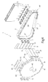
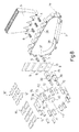
packing machine 1 for producingpacket 56, packing path P2 is defined by changingpacking wheel 40 onshaft 42 with apacking wheel 70, which comprises anoctagonal plate 71 having, along eachside 72, two tubular throughspindles 73 parallel toaxis 43. Eachtubular spindle 73 projects from the front ofoctagonal plate 71, has a firstrounded edge 74 facing radially outwards and parallel toaxis 43, and two furtherrounded edges 75 facingaxis 43, and defines a throughconduit 76 of the same shape in cross section asgroups 6 of cigarettes, and which is fed axially, attransfer station 11, with arespective group 6 of cigarettes complete withinner sheet 10 of packing material and issuing fromrespective folding conduit 39. - As shown more clearly in
Figure 10 , eachtubular spindle 73 is fed simultaneously, at loadingstation 45, with respective collar 12' and respective outer blank 16, which are superimposed beforehand so that the centralaxial band 63 of the blank is parallel toaxis 43 and faces both the centralaxial band 58 of collar 12' andedge 74. - In a variation not shown, collar 12' and outer blank 16 are fed successively onto
tubular spindle 73. - Since collar 12' and relative outer blank 16 are supplied flat to loading
station 45, and packingwheel 70 is the same size as packingwheel 40, threetubular spindles 73 cannot be provided along eachside 72 ofpacking wheel 70. Consequently, the number oftubular spindles 73 perside 72, the number offolding conduits 39, and the number of formingpockets 3 loaded simultaneously are reduced to two. - Next (
Figure 11 ), collar 12' and relative outer blank 16 are lowered simultaneously ontoedge 74 and folded gradually (Figures 12, 13 ) abouttubular spindle 73; and anend wall 78 ofpacket 56 is simultaneously formed over theoutlet 77 ofconduit 76 by squarely folding eachaxial tab 68 andrelative tab 61 projecting axially outwards ofoutlet 77, and then squarely folding relativeaxial tab 69. Before reachingtransfer station 17, a cup-shapedpackage 79 is thus formed on eachtubular spindle 73, and theend wall 78 of which closesoutlet 77 ofconduit 76. - Each
group 6 of cigarettes, complete with respectiveinner sheet 10 of packing material, is first pushed axially intoconduit 76 of respectivetubular spindle 73 and into contact withend wall 78 of respective cup-shapedpackage 79 attransfer station 11, and is then pushed further axially at transfer station 17 (which, in theFigure 8 and9 example, coincides with transfer station 13) so as to slide out oftubular spindle 73, taking respective cup-shapedpackage 79 with it, and penetrate axially, together with cup-shapedpackage 79, inside a respectivetubular packing pocket 80 of an endless-belt packing conveyor 81 defining packing path P4 and moving in steps in a direction perpendicular to packing pockets 80. - In connection with the above, it should be pointed out that cup-shaped
package 79 and relative collar 12' are unloaded simultaneously from relativetubular spindle 73 attransfer station 17 by virtue of collar 12' comprisingtabs 61, which, once folded squarely overoutlet 77 oftubular spindle 73, form an integral part ofend wall 78.Tabs 61 may obviously be replaced with any mechanical system for fastening outer blank 16 to relative collar 12', or simply by a spot of glue. - As it travels along path P4, each
packet 56 is completed by squarely foldingaxial tabs wall 78, by means of known folding devices (not shown), and is expelled axially fromrelative packing pocket 80 at an unloadingstation 82 and fed to a drying conveyor (not shown). - As shown in
Figure 9 , packingconveyor 81 is preferably supported by abox frame 83, which is connected to the frame of packingmachine 1 over, and without dismantling, packingwheel 14.
Claims (15)
- A packing method for producing packets (56) of cigarettes on a packing machine; the method comprising the steps of:forming groups (6) of cigarettes by expelling the cigarettes from a cigarette hopper (5);feeding the groups (6) of cigarettes, by means of a first packing conveyor (8), along a first packing path (P1), along which an inner sheet (10) of packing material is folded about each group (6) of cigarettes;transferring the groups (6) of cigarettes from the first packing path (P1) to a second packing path (P2);feeding the groups (6) of cigarettes, by means of a second packing conveyor (70), along the second packing path (P2), along which a collar (12') and/or an outer blank (16) are folded about each group (6) of cigarettes and on top of the inner sheet (10) of packing material;the method being characterized by comprising the further steps of:feeding a relative collar (12') and/or a relative outer blank (16) onto a relative tubular spindle (73), which is movable along the second packing path (P2), so that the outer blank (16) can be superimposed on the collar (12');feeding the relative group (6) of cigarettes, wrapped in the respective inner sheet (10) of packing material, into the relative tubular spindle (73); andfolding the collar (12') and/or the outer blank (16) about the tubular spindle (73) to form, on the tubular spindle (73) containing the group (6) of cigarettes wrapped in the inner sheet (10) of packing material, a cup-shaped package (79), an end wall (78) of which closes an outlet (77) of the tubular spindle (73).
- A method as claimed in Claim 1, and comprising the further step of first superimposing the outer blank (16) on the collar (12') to feed the superimposed outer blank (16) and collar (12') together onto the relative tubular spindle (73).
- A method as claimed in Claim 1 or 2, wherein the cup-shaped package (79) and the relative group (6) of cigarettes are removed axially from the tubular spindle (73) by pushing the group (6) of cigarettes.
- A method as claimed in Claim 1, 2 or 3, and comprising the further steps of:transferring the cup-shaped package (79) and relative group (6) of cigarettes axially from the tubular spindle (73) into a pocket (80) of a third packing conveyor (18) defining a third packing path (P4); andcompleting folding of the outer blank (16), to close the cup-shaped package (79), as the outer blank travels along the third packing path (P4).
- A method as claimed in Claim 4, wherein the third packing conveyor (18) comprises a belt conveyor (81) comprising a number of tubular pockets (80); each group (6) of cigarettes being fed axially into a relative tubular pocket (80) of the belt conveyor (81), and being expelled axially from the tubular pocket (80).
- A method as claimed in any one of Claims 1 to 5, wherein forming a packet (56) of cigarettes comprises the steps of:folding a relative collar (12') together with a relative outer blank (16) about the relative group (6) of cigarettes along the second packing path (P2); andcompleting folding of the outer blank (16) about the relative group (6) of cigarettes and on top of the relative collar (12') along a third packing path (P4) following the second packing path (P2).
- A method as claimed in any one of Claims 1 to 6, wherein:the second packing conveyor (70) comprises a first packing wheel (70) for folding the collar (12') and/or, partly, the outer blank (16) about each group (6) of cigarettes; folding of the outer blank (16) about each group (6) of cigarettes being completed as the relative group (6) of cigarettes is advanced by the third packing conveyor (18); andthe first packing wheel (70) comprises a number of tubular spindles (73); each group (6) of cigarettes being fed into a relative tubular spindle (73); and the relative collar (12') and/or outer blank (16) being folded on an outer surface of the tubular spindle (73).
- A method as claimed in Claim 7, wherein each group (6) of cigarettes is fed axially from the first packing conveyor (8) to the relative tubular spindle (73) of the first packing wheel (70), and is removed axially from the relative tubular spindle (73).
- A method as claimed in any one of Claims 1 to 8, and comprising the further step of securing the collar (12') and the outer blank (16) axially to each other.
- A method as claimed in Claim 9, wherein the collar (12') and the outer blank (16) are secured axially to each other by folding at least one portion (61) of the collar (12') to form part of the end wall (78) of the cup-shaped package (79).
- A method as claimed in any one of Claims 1 to 10, wherein the collar (12') and/or outer blank (16) are fed to the tubular spindle (73) before the relative group (6) of cigarettes.
- A packing machine for producing packets (56) of cigarettes; the packing machine comprising:a cigarette hopper (5), from which the cigarettes are expelled to form groups (6) of cigarettes;a first packing conveyor (8) extending through a first loading station (9) for loading a succession of inner sheets (10) of packing material; the first packing conveyor (8) feeding the groups (6) of cigarettes along a first packing path (P1), along which a respective inner sheet (10) of packing material is folded about each group (6) of cigarettes;a first transfer station (7) for transferring the groups (6) of cigarettes from the forming path (PF) to the first packing path (P1);a second packing conveyor (70) extending through a second loading station (45) for loading a succession of collars (12') and/or a succession of outer blanks (16); the second packing conveyor (70) feeding the groups (6) of cigarettes along a second packing path (P2), along which a respective collar (12') and/or a respective outer blank (16) are folded about each group (6) of cigarettes and on top of the relative inner sheet (10) of packing material; anda second transfer station (11) for transferring the groups (6) of cigarettes from the first packing path (P1) to the second packing path (P2);the packing machine (1) being characterized in that the second packing conveyor (70) comprises a number of axial tubular spindles (73), each for receiving internally a relative group (6) of cigarettes wrapped in the respective inner sheet (10) of packing material, and for receiving externally, on a respective outer surface, a relative collar (12') and/or a relative outer blank (16) for folding the collar (12') and/or the outer blank (16) about the tubular spindle (73) to form, on the tubular spindle (73), a cup-shaped package (79), an end wall (78) of which closes an outlet (77) of the tubular spindle (73).
- A packing machine as claimed in Claim 12, wherein:the second packing conveyor (70) comprises a first packing wheel (70) for folding a second collar (12') and/or, partly, a second outer blank (16) about each group (6) of cigarettes; the third packing conveyor (18) completing folding of each second outer blank (16) about the relative group (6) of cigarettes; andthe first packing wheel (70) comprises a number of axial tubular spindles (73), each for receiving internally a relative group (6) of cigarettes, and for receiving externally, on a respective outer surface, a relative second collar (12') and/or a relative second outer blank (16).
- A packing machine as claimed in Claim 12 or 13 and comprising a third packing conveyor (18) for receiving the groups (6) of cigarettes successively from the second packing conveyor (70); the third packing conveyor (18) feeding the groups (6) of cigarettes along a third packing path (P4), along which folding of a outer blank (16) about each group (6) of cigarettes is completed to form a packet (56) of cigarettes.
- A packing machine as claimed in Claim 12, 13 or 14, wherein the second collar (12') and/or second outer blank (16) are fed to the tubular spindle (73) before the relative group (6) of cigarettes.
Applications Claiming Priority (3)
| Application Number | Priority Date | Filing Date | Title |
|---|---|---|---|
| IT000419A ITBO20060419A1 (en) | 2006-05-30 | 2006-05-30 | METHOD AND WRAPPING MACHINE FOR THE CREATION OF CIGARETTE PACKAGES. |
| EP09163322A EP2096034B1 (en) | 2006-05-30 | 2007-05-29 | Packing method and machine for producing packets of cigarettes |
| EP07109149A EP1862387A3 (en) | 2006-05-30 | 2007-05-29 | Packing method and machine for producing packets of cigarettes |
Related Parent Applications (2)
| Application Number | Title | Priority Date | Filing Date |
|---|---|---|---|
| EP07109149.0 Division | 2007-05-29 | ||
| EP09163322.2 Division | 2009-06-19 |
Publications (3)
| Publication Number | Publication Date |
|---|---|
| EP2221252A2 true EP2221252A2 (en) | 2010-08-25 |
| EP2221252A3 EP2221252A3 (en) | 2010-09-22 |
| EP2221252B1 EP2221252B1 (en) | 2012-02-15 |
Family
ID=38354365
Family Applications (3)
| Application Number | Title | Priority Date | Filing Date |
|---|---|---|---|
| EP07109149A Pending EP1862387A3 (en) | 2006-05-30 | 2007-05-29 | Packing method and machine for producing packets of cigarettes |
| EP09163322A Active EP2096034B1 (en) | 2006-05-30 | 2007-05-29 | Packing method and machine for producing packets of cigarettes |
| EP10163550A Not-in-force EP2221252B1 (en) | 2006-05-30 | 2007-05-29 | Packing method and machine for producing packets of cigarettes |
Family Applications Before (2)
| Application Number | Title | Priority Date | Filing Date |
|---|---|---|---|
| EP07109149A Pending EP1862387A3 (en) | 2006-05-30 | 2007-05-29 | Packing method and machine for producing packets of cigarettes |
| EP09163322A Active EP2096034B1 (en) | 2006-05-30 | 2007-05-29 | Packing method and machine for producing packets of cigarettes |
Country Status (6)
| Country | Link |
|---|---|
| US (1) | US7650730B2 (en) |
| EP (3) | EP1862387A3 (en) |
| CN (1) | CN101081647A (en) |
| AT (2) | ATE545587T1 (en) |
| DE (1) | DE602007013938D1 (en) |
| IT (1) | ITBO20060419A1 (en) |
Cited By (1)
| Publication number | Priority date | Publication date | Assignee | Title |
|---|---|---|---|---|
| CN104229180A (en) * | 2014-08-29 | 2014-12-24 | 北京天申正祥科技有限公司 | Full open type cigarette multi-path cartoning equipment |
Families Citing this family (19)
| Publication number | Priority date | Publication date | Assignee | Title |
|---|---|---|---|---|
| EP2033896A1 (en) * | 2004-08-11 | 2009-03-11 | Philip Morris Products S.A. | Substantially air-tight, self sealing container for cigarettes |
| ITBO20050595A1 (en) * | 2005-10-06 | 2006-01-05 | Gd Spa | METHOD AND MACHINE FOR THE WRAPPING OF A PRODUCT IN AT LEAST ONE SHEET OF PAPER |
| ITBO20060587A1 (en) * | 2006-08-03 | 2008-02-04 | Gd Spa | CIGARETTE PACKAGING MACHINE FOR THE CREATION OF RIGID PACKAGES WITH HINGED LID. |
| GB0701257D0 (en) * | 2007-01-23 | 2007-02-28 | British American Tobacco Co | Machine, method, and system for packaging smoking products |
| DE102008010433A1 (en) * | 2008-02-21 | 2009-08-27 | Focke & Co.(Gmbh & Co. Kg) | Method and device for producing packages for folding box type cigarettes |
| US20090265954A1 (en) * | 2008-04-23 | 2009-10-29 | Franne Goldberg | Shoe and Sandal Footwear Combination |
| ITBO20080327A1 (en) * | 2008-05-26 | 2009-11-27 | Gd Spa | METHOD AND UNITS TO FOLD A SHEET OF PAPERS AROUND A GROUP OF CIGARETTES. |
| IT1394894B1 (en) * | 2009-04-17 | 2012-07-20 | Gima Spa | DEVICE FOR PACKAGING A PRODUCT IN A BOX |
| IT1397936B1 (en) * | 2010-01-26 | 2013-02-04 | Gima Spa | PACKING MACHINE AND METHOD FOR PACKAGING SMOKE ITEMS. |
| KR101345694B1 (en) * | 2011-03-11 | 2013-12-30 | 옵토팩 주식회사 | Fiber, Fiber aggregate and Adhesive having the same |
| ITBO20110378A1 (en) * | 2011-06-29 | 2012-12-30 | Gd Spa | CIGARETTE PACKAGING MACHINE. |
| ITBO20120336A1 (en) * | 2012-06-20 | 2013-12-21 | Sasib Spa | METHOD AND EQUIPMENT FOR FILLING CONTAINERS WITH BAR-SHAPED ITEMS. |
| ITBO20130018A1 (en) * | 2013-01-18 | 2014-07-19 | Gd Spa | WRAPPING MACHINE AND SETTING METHOD TO REALIZE A RIGID PACKAGE OF SMOKE ITEMS. |
| PL3070006T3 (en) * | 2015-03-18 | 2018-02-28 | G.D Societa' Per Azioni | Wrapping method and packer machine to fold a wrapper around a group of tobacco articles |
| DE102015110682A1 (en) * | 2015-07-02 | 2017-01-05 | Focke & Co. (Gmbh & Co. Kg) | Device for producing packages for cigarettes |
| CN106394973B (en) * | 2016-11-09 | 2018-11-20 | 宁波升瀚烟草机械有限公司 | A kind of cigarette can packing machine |
| CN106379602B (en) * | 2016-11-09 | 2018-11-02 | 宁波升瀚烟草机械有限公司 | A kind of draw and cigarette tinning mechanism of cigarette can packing machine |
| IT201800009892A1 (en) * | 2018-10-30 | 2020-04-30 | Sasib Spa | Packaging machine |
| US20210016908A1 (en) * | 2019-07-19 | 2021-01-21 | Aiger Group Ag | Apparatus, system, and method for filling of rod-shaped articles in packaging |
Citations (3)
| Publication number | Priority date | Publication date | Assignee | Title |
|---|---|---|---|---|
| EP0414532A1 (en) | 1989-08-22 | 1991-02-27 | Tobacco Research and Development Institute Limited | Flip-top cartons |
| EP0481305A1 (en) | 1990-10-18 | 1992-04-22 | SASIB S.p.A. | Cigarette packing machine, specifically for packaging cigarettes into hard boxes with integral hinged lids |
| WO2007091029A1 (en) | 2006-02-08 | 2007-08-16 | British American Tobacco (Investments) Limited | Blank for forming a prismatic pack of triangular cross-section, pack and method and apparatus for making a pack |
Family Cites Families (13)
| Publication number | Priority date | Publication date | Assignee | Title |
|---|---|---|---|---|
| US4004395A (en) * | 1972-01-06 | 1977-01-25 | Hauni-Werke Korber & Co., Kg | Method and machine for the production of hinged-lid packs for groups of cigarettes or the like |
| IT1245759B (en) * | 1991-01-25 | 1994-10-14 | Gd Spa | CIGARETTE PACKING MACHINE IN RIGID HINGED LID PACKAGES. |
| GB9514453D0 (en) * | 1995-07-14 | 1995-09-13 | Molins Plc | Packaging apparatus |
| US6173551B1 (en) * | 1998-04-07 | 2001-01-16 | Philip Morris Incorporated | Ink jet coder system and method |
| US6373519B1 (en) * | 1998-10-15 | 2002-04-16 | Philip Morris Incorporated | System and method for visually inspecting a cigarette packaging process |
| GB9913223D0 (en) * | 1999-06-07 | 1999-08-04 | Molins Plc | Wrapping apparatus and method |
| DE19947709A1 (en) * | 1999-10-04 | 2001-04-05 | Topack Verpacktech Gmbh | Cigarette packing method uses machine with main drive which stops on appearance of signal and second drive which operates section of packing machine during and after halting of main drive |
| IT1320970B1 (en) * | 2000-04-04 | 2003-12-18 | Gd Spa | MACHINE FOR MAKING CIGARETTE PACKAGES AND METHOD OF CONTROL OF THE MACHINE. |
| EP1321363B1 (en) | 2000-09-27 | 2008-07-16 | Japan Tobacco Inc. | Packaging material folding device of packaging machine |
| DE10158736A1 (en) * | 2001-11-30 | 2003-06-12 | Focke & Co | Method and device for manufacturing hard packs for cigarettes |
| ATE356028T1 (en) * | 2003-05-09 | 2007-03-15 | Hauni Primary Internat Gmbh | MACHINE FOR PRODUCING CIGARETTE PACKS |
| JP2007527827A (en) | 2004-03-11 | 2007-10-04 | ジ・ディ・ソシエタ・ペル・アチオニ | Cigarette packing machine |
| ITBO20050235A1 (en) * | 2005-04-13 | 2005-07-13 | Gd Spa | CIGARETTE PACKAGING MACHINE FOR THE CREATION OF RIGID PACKAGES WITH HINGED LID |
-
2006
- 2006-05-30 IT IT000419A patent/ITBO20060419A1/en unknown
-
2007
- 2007-05-29 DE DE602007013938T patent/DE602007013938D1/en active Active
- 2007-05-29 EP EP07109149A patent/EP1862387A3/en active Pending
- 2007-05-29 EP EP09163322A patent/EP2096034B1/en active Active
- 2007-05-29 US US11/807,595 patent/US7650730B2/en not_active Expired - Fee Related
- 2007-05-29 AT AT10163550T patent/ATE545587T1/en active
- 2007-05-29 AT AT09163322T patent/ATE505402T1/en not_active IP Right Cessation
- 2007-05-29 EP EP10163550A patent/EP2221252B1/en not_active Not-in-force
- 2007-05-30 CN CNA2007101379053A patent/CN101081647A/en active Pending
Patent Citations (3)
| Publication number | Priority date | Publication date | Assignee | Title |
|---|---|---|---|---|
| EP0414532A1 (en) | 1989-08-22 | 1991-02-27 | Tobacco Research and Development Institute Limited | Flip-top cartons |
| EP0481305A1 (en) | 1990-10-18 | 1992-04-22 | SASIB S.p.A. | Cigarette packing machine, specifically for packaging cigarettes into hard boxes with integral hinged lids |
| WO2007091029A1 (en) | 2006-02-08 | 2007-08-16 | British American Tobacco (Investments) Limited | Blank for forming a prismatic pack of triangular cross-section, pack and method and apparatus for making a pack |
Cited By (1)
| Publication number | Priority date | Publication date | Assignee | Title |
|---|---|---|---|---|
| CN104229180A (en) * | 2014-08-29 | 2014-12-24 | 北京天申正祥科技有限公司 | Full open type cigarette multi-path cartoning equipment |
Also Published As
| Publication number | Publication date |
|---|---|
| EP2221252A3 (en) | 2010-09-22 |
| EP2221252B1 (en) | 2012-02-15 |
| EP1862387A2 (en) | 2007-12-05 |
| ATE505402T1 (en) | 2011-04-15 |
| US7650730B2 (en) | 2010-01-26 |
| DE602007013938D1 (en) | 2011-05-26 |
| ITBO20060419A1 (en) | 2006-08-29 |
| US20070289259A1 (en) | 2007-12-20 |
| CN101081647A (en) | 2007-12-05 |
| EP2096034A1 (en) | 2009-09-02 |
| EP2096034B1 (en) | 2011-04-13 |
| EP1862387A3 (en) | 2008-01-02 |
| ATE545587T1 (en) | 2012-03-15 |
Similar Documents
| Publication | Publication Date | Title |
|---|---|---|
| EP2221252B1 (en) | Packing method and machine for producing packets of cigarettes | |
| US5003755A (en) | Method and device for producing tubular wrappings | |
| EP1712470B1 (en) | Cigarette packing machine for producing rigid hinged-lid packets | |
| KR102586941B1 (en) | Packer machine and wrapping method to manufacture a packet of tobacco articles containing two distinct groups of tobacco articles | |
| US5906087A (en) | Blank gumming method for cigarette packing machines | |
| US6439239B1 (en) | Method for forming a packet of cigarettes | |
| EP0529404A1 (en) | Device for packing packets, particularly of cigarettes, in groups | |
| JP2006027733A (en) | Method for packaging pair of wrapped tobacco groups in wallet packet having hinged lid | |
| EP0741081B1 (en) | Method and machine for packing products and subsequent drying of the packages | |
| CN101293570B (en) | Cigarette packing machine and method for producing slide-open cigarette | |
| CA1302372C (en) | Packaging machine, especially for cigarette packs | |
| EP0860358A1 (en) | Product wrapping method and machine | |
| EP3070006B1 (en) | Wrapping method and packer machine to fold a wrapper around a group of tobacco articles | |
| EP3222532B1 (en) | Orientation unit and method for causing a change in orientation of a parallelepiped-shaped article in a packing machine | |
| EP1854724B1 (en) | Method and packing machine for producing packets of cigarettes | |
| CN1974329B (en) | Method and machine for packing a product in at least one sheet of packing material | |
| EP0900731B1 (en) | Packing machine | |
| EP0792807B1 (en) | Method and unit for folding packing blanks along preformed bend lines | |
| EP3070005B1 (en) | Wrapping method and packer machine to manufacture packets of tobacco articles, each containing two distinct groups of tobacco articles | |
| EP3222535B1 (en) | Packaging machine and wrapping method for the production of a pack of tobacco articles | |
| EP3222537B1 (en) | Packaging machine and wrapping method for the production of a pack of tobacco articles | |
| EP1772382A1 (en) | Method and unit for transferring a product on an intermittent packing machine | |
| EP3222538B1 (en) | Wrapping unit and method | |
| EP3216708B1 (en) | Machine and method for making cigarette packets of the "shoulder box" type | |
| EP4717613A1 (en) | Packer machine and wrapping method for producing a rigid pack for smoking articles with a hinged lid |
Legal Events
| Date | Code | Title | Description |
|---|---|---|---|
| PUAI | Public reference made under article 153(3) epc to a published international application that has entered the european phase |
Free format text: ORIGINAL CODE: 0009012 |
|
| PUAL | Search report despatched |
Free format text: ORIGINAL CODE: 0009013 |
|
| AC | Divisional application: reference to earlier application |
Ref document number: 1862387 Country of ref document: EP Kind code of ref document: P Ref document number: 2096034 Country of ref document: EP Kind code of ref document: P |
|
| AK | Designated contracting states |
Kind code of ref document: A2 Designated state(s): AT BE BG CH CY CZ DE DK EE ES FI FR GB GR HU IE IS IT LI LT LU LV MC MT NL PL PT RO SE SI SK TR |
|
| AK | Designated contracting states |
Kind code of ref document: A3 Designated state(s): AT BE BG CH CY CZ DE DK EE ES FI FR GB GR HU IE IS IT LI LT LU LV MC MT NL PL PT RO SE SI SK TR |
|
| RIC1 | Information provided on ipc code assigned before grant |
Ipc: B65B 19/20 20060101ALI20100818BHEP Ipc: B65B 59/04 20060101ALI20100818BHEP Ipc: B65B 59/00 20060101ALI20100818BHEP Ipc: B65B 19/24 20060101ALI20100818BHEP Ipc: B65B 19/22 20060101AFI20100706BHEP |
|
| 17P | Request for examination filed |
Effective date: 20110322 |
|
| 17Q | First examination report despatched |
Effective date: 20110503 |
|
| GRAP | Despatch of communication of intention to grant a patent |
Free format text: ORIGINAL CODE: EPIDOSNIGR1 |
|
| RIC1 | Information provided on ipc code assigned before grant |
Ipc: B65B 19/24 20060101ALI20110816BHEP Ipc: B65B 19/22 20060101AFI20110816BHEP Ipc: B65B 59/00 20060101ALI20110816BHEP Ipc: B65B 59/04 20060101ALI20110816BHEP Ipc: B65B 19/20 20060101ALI20110816BHEP |
|
| GRAS | Grant fee paid |
Free format text: ORIGINAL CODE: EPIDOSNIGR3 |
|
| GRAA | (expected) grant |
Free format text: ORIGINAL CODE: 0009210 |
|
| AC | Divisional application: reference to earlier application |
Ref document number: 1862387 Country of ref document: EP Kind code of ref document: P Ref document number: 2096034 Country of ref document: EP Kind code of ref document: P |
|
| AK | Designated contracting states |
Kind code of ref document: B1 Designated state(s): AT BE BG CH CY CZ DE DK EE ES FI FR GB GR HU IE IS IT LI LT LU LV MC MT NL PL PT RO SE SI SK TR |
|
| REG | Reference to a national code |
Ref country code: GB Ref legal event code: FG4D Ref country code: CH Ref legal event code: EP |
|
| REG | Reference to a national code |
Ref country code: IE Ref legal event code: FG4D |
|
| REG | Reference to a national code |
Ref country code: AT Ref legal event code: REF Ref document number: 545587 Country of ref document: AT Kind code of ref document: T Effective date: 20120315 |
|
| REG | Reference to a national code |
Ref country code: DE Ref legal event code: R096 Ref document number: 602007020777 Country of ref document: DE Effective date: 20120412 |
|
| REG | Reference to a national code |
Ref country code: CH Ref legal event code: NV Representative=s name: HEPP WENGER RYFFEL AG |
|
| REG | Reference to a national code |
Ref country code: NL Ref legal event code: VDEP Effective date: 20120215 |
|
| LTIE | Lt: invalidation of european patent or patent extension |
Effective date: 20120215 |
|
| PG25 | Lapsed in a contracting state [announced via postgrant information from national office to epo] |
Ref country code: NL Free format text: LAPSE BECAUSE OF FAILURE TO SUBMIT A TRANSLATION OF THE DESCRIPTION OR TO PAY THE FEE WITHIN THE PRESCRIBED TIME-LIMIT Effective date: 20120215 Ref country code: LT Free format text: LAPSE BECAUSE OF FAILURE TO SUBMIT A TRANSLATION OF THE DESCRIPTION OR TO PAY THE FEE WITHIN THE PRESCRIBED TIME-LIMIT Effective date: 20120215 Ref country code: IS Free format text: LAPSE BECAUSE OF FAILURE TO SUBMIT A TRANSLATION OF THE DESCRIPTION OR TO PAY THE FEE WITHIN THE PRESCRIBED TIME-LIMIT Effective date: 20120615 |
|
| PGFP | Annual fee paid to national office [announced via postgrant information from national office to epo] |
Ref country code: CH Payment date: 20120525 Year of fee payment: 6 |
|
| PG25 | Lapsed in a contracting state [announced via postgrant information from national office to epo] |
Ref country code: FI Free format text: LAPSE BECAUSE OF FAILURE TO SUBMIT A TRANSLATION OF THE DESCRIPTION OR TO PAY THE FEE WITHIN THE PRESCRIBED TIME-LIMIT Effective date: 20120215 Ref country code: BE Free format text: LAPSE BECAUSE OF FAILURE TO SUBMIT A TRANSLATION OF THE DESCRIPTION OR TO PAY THE FEE WITHIN THE PRESCRIBED TIME-LIMIT Effective date: 20120215 Ref country code: PT Free format text: LAPSE BECAUSE OF FAILURE TO SUBMIT A TRANSLATION OF THE DESCRIPTION OR TO PAY THE FEE WITHIN THE PRESCRIBED TIME-LIMIT Effective date: 20120615 Ref country code: GR Free format text: LAPSE BECAUSE OF FAILURE TO SUBMIT A TRANSLATION OF THE DESCRIPTION OR TO PAY THE FEE WITHIN THE PRESCRIBED TIME-LIMIT Effective date: 20120516 Ref country code: LV Free format text: LAPSE BECAUSE OF FAILURE TO SUBMIT A TRANSLATION OF THE DESCRIPTION OR TO PAY THE FEE WITHIN THE PRESCRIBED TIME-LIMIT Effective date: 20120215 Ref country code: PL Free format text: LAPSE BECAUSE OF FAILURE TO SUBMIT A TRANSLATION OF THE DESCRIPTION OR TO PAY THE FEE WITHIN THE PRESCRIBED TIME-LIMIT Effective date: 20120215 |
|
| REG | Reference to a national code |
Ref country code: AT Ref legal event code: MK05 Ref document number: 545587 Country of ref document: AT Kind code of ref document: T Effective date: 20120215 |
|
| PG25 | Lapsed in a contracting state [announced via postgrant information from national office to epo] |
Ref country code: CY Free format text: LAPSE BECAUSE OF FAILURE TO SUBMIT A TRANSLATION OF THE DESCRIPTION OR TO PAY THE FEE WITHIN THE PRESCRIBED TIME-LIMIT Effective date: 20120215 |
|
| PG25 | Lapsed in a contracting state [announced via postgrant information from national office to epo] |
Ref country code: DK Free format text: LAPSE BECAUSE OF FAILURE TO SUBMIT A TRANSLATION OF THE DESCRIPTION OR TO PAY THE FEE WITHIN THE PRESCRIBED TIME-LIMIT Effective date: 20120215 Ref country code: SE Free format text: LAPSE BECAUSE OF FAILURE TO SUBMIT A TRANSLATION OF THE DESCRIPTION OR TO PAY THE FEE WITHIN THE PRESCRIBED TIME-LIMIT Effective date: 20120215 Ref country code: EE Free format text: LAPSE BECAUSE OF FAILURE TO SUBMIT A TRANSLATION OF THE DESCRIPTION OR TO PAY THE FEE WITHIN THE PRESCRIBED TIME-LIMIT Effective date: 20120215 Ref country code: CZ Free format text: LAPSE BECAUSE OF FAILURE TO SUBMIT A TRANSLATION OF THE DESCRIPTION OR TO PAY THE FEE WITHIN THE PRESCRIBED TIME-LIMIT Effective date: 20120215 Ref country code: SI Free format text: LAPSE BECAUSE OF FAILURE TO SUBMIT A TRANSLATION OF THE DESCRIPTION OR TO PAY THE FEE WITHIN THE PRESCRIBED TIME-LIMIT Effective date: 20120215 Ref country code: RO Free format text: LAPSE BECAUSE OF FAILURE TO SUBMIT A TRANSLATION OF THE DESCRIPTION OR TO PAY THE FEE WITHIN THE PRESCRIBED TIME-LIMIT Effective date: 20120215 |
|
| PLBI | Opposition filed |
Free format text: ORIGINAL CODE: 0009260 |
|
| PG25 | Lapsed in a contracting state [announced via postgrant information from national office to epo] |
Ref country code: SK Free format text: LAPSE BECAUSE OF FAILURE TO SUBMIT A TRANSLATION OF THE DESCRIPTION OR TO PAY THE FEE WITHIN THE PRESCRIBED TIME-LIMIT Effective date: 20120215 Ref country code: IT Free format text: LAPSE BECAUSE OF FAILURE TO SUBMIT A TRANSLATION OF THE DESCRIPTION OR TO PAY THE FEE WITHIN THE PRESCRIBED TIME-LIMIT Effective date: 20120215 |
|
| 26 | Opposition filed |
Opponent name: FOCKE & CO. (GMBH & CO. KG) Effective date: 20121029 |
|
| PLAX | Notice of opposition and request to file observation + time limit sent |
Free format text: ORIGINAL CODE: EPIDOSNOBS2 |
|
| PG25 | Lapsed in a contracting state [announced via postgrant information from national office to epo] |
Ref country code: MC Free format text: LAPSE BECAUSE OF NON-PAYMENT OF DUE FEES Effective date: 20120531 |
|
| REG | Reference to a national code |
Ref country code: DE Ref legal event code: R026 Ref document number: 602007020777 Country of ref document: DE Effective date: 20121029 |
|
| PG25 | Lapsed in a contracting state [announced via postgrant information from national office to epo] |
Ref country code: AT Free format text: LAPSE BECAUSE OF FAILURE TO SUBMIT A TRANSLATION OF THE DESCRIPTION OR TO PAY THE FEE WITHIN THE PRESCRIBED TIME-LIMIT Effective date: 20120215 |
|
| REG | Reference to a national code |
Ref country code: IE Ref legal event code: MM4A |
|
| REG | Reference to a national code |
Ref country code: FR Ref legal event code: ST Effective date: 20130131 |
|
| PLBB | Reply of patent proprietor to notice(s) of opposition received |
Free format text: ORIGINAL CODE: EPIDOSNOBS3 |
|
| PG25 | Lapsed in a contracting state [announced via postgrant information from national office to epo] |
Ref country code: IE Free format text: LAPSE BECAUSE OF NON-PAYMENT OF DUE FEES Effective date: 20120529 Ref country code: FR Free format text: LAPSE BECAUSE OF NON-PAYMENT OF DUE FEES Effective date: 20120531 Ref country code: ES Free format text: LAPSE BECAUSE OF FAILURE TO SUBMIT A TRANSLATION OF THE DESCRIPTION OR TO PAY THE FEE WITHIN THE PRESCRIBED TIME-LIMIT Effective date: 20120526 |
|
| PG25 | Lapsed in a contracting state [announced via postgrant information from national office to epo] |
Ref country code: MT Free format text: LAPSE BECAUSE OF FAILURE TO SUBMIT A TRANSLATION OF THE DESCRIPTION OR TO PAY THE FEE WITHIN THE PRESCRIBED TIME-LIMIT Effective date: 20120215 Ref country code: BG Free format text: LAPSE BECAUSE OF FAILURE TO SUBMIT A TRANSLATION OF THE DESCRIPTION OR TO PAY THE FEE WITHIN THE PRESCRIBED TIME-LIMIT Effective date: 20120515 |
|
| REG | Reference to a national code |
Ref country code: CH Ref legal event code: PL |
|
| PG25 | Lapsed in a contracting state [announced via postgrant information from national office to epo] |
Ref country code: LI Free format text: LAPSE BECAUSE OF NON-PAYMENT OF DUE FEES Effective date: 20130531 Ref country code: CH Free format text: LAPSE BECAUSE OF NON-PAYMENT OF DUE FEES Effective date: 20130531 |
|
| PG25 | Lapsed in a contracting state [announced via postgrant information from national office to epo] |
Ref country code: TR Free format text: LAPSE BECAUSE OF FAILURE TO SUBMIT A TRANSLATION OF THE DESCRIPTION OR TO PAY THE FEE WITHIN THE PRESCRIBED TIME-LIMIT Effective date: 20120215 |
|
| REG | Reference to a national code |
Ref country code: DE Ref legal event code: R100 Ref document number: 602007020777 Country of ref document: DE |
|
| PG25 | Lapsed in a contracting state [announced via postgrant information from national office to epo] |
Ref country code: LU Free format text: LAPSE BECAUSE OF NON-PAYMENT OF DUE FEES Effective date: 20120529 |
|
| PLCK | Communication despatched that opposition was rejected |
Free format text: ORIGINAL CODE: EPIDOSNREJ1 |
|
| PG25 | Lapsed in a contracting state [announced via postgrant information from national office to epo] |
Ref country code: HU Free format text: LAPSE BECAUSE OF FAILURE TO SUBMIT A TRANSLATION OF THE DESCRIPTION OR TO PAY THE FEE WITHIN THE PRESCRIBED TIME-LIMIT Effective date: 20070529 |
|
| PLBN | Opposition rejected |
Free format text: ORIGINAL CODE: 0009273 |
|
| STAA | Information on the status of an ep patent application or granted ep patent |
Free format text: STATUS: OPPOSITION REJECTED |
|
| 27O | Opposition rejected |
Effective date: 20140513 |
|
| REG | Reference to a national code |
Ref country code: DE Ref legal event code: R100 Ref document number: 602007020777 Country of ref document: DE Effective date: 20140513 |
|
| PGFP | Annual fee paid to national office [announced via postgrant information from national office to epo] |
Ref country code: GB Payment date: 20160527 Year of fee payment: 10 Ref country code: DE Payment date: 20160527 Year of fee payment: 10 |
|
| REG | Reference to a national code |
Ref country code: DE Ref legal event code: R119 Ref document number: 602007020777 Country of ref document: DE |
|
| GBPC | Gb: european patent ceased through non-payment of renewal fee |
Effective date: 20170529 |
|
| PG25 | Lapsed in a contracting state [announced via postgrant information from national office to epo] |
Ref country code: GB Free format text: LAPSE BECAUSE OF NON-PAYMENT OF DUE FEES Effective date: 20170529 Ref country code: DE Free format text: LAPSE BECAUSE OF NON-PAYMENT OF DUE FEES Effective date: 20171201 |