EP2221229A1 - Ensemble de transport pour une tente repliée, ou autre objet volumineux similaire - Google Patents
Ensemble de transport pour une tente repliée, ou autre objet volumineux similaire Download PDFInfo
- Publication number
- EP2221229A1 EP2221229A1 EP10153779A EP10153779A EP2221229A1 EP 2221229 A1 EP2221229 A1 EP 2221229A1 EP 10153779 A EP10153779 A EP 10153779A EP 10153779 A EP10153779 A EP 10153779A EP 2221229 A1 EP2221229 A1 EP 2221229A1
- Authority
- EP
- European Patent Office
- Prior art keywords
- tent
- cover
- transport
- transport device
- rigid structure
- Prior art date
- Legal status (The legal status is an assumption and is not a legal conclusion. Google has not performed a legal analysis and makes no representation as to the accuracy of the status listed.)
- Granted
Links
- 239000000463 material Substances 0.000 claims abstract description 24
- 230000000295 complement effect Effects 0.000 claims abstract description 6
- 230000000712 assembly Effects 0.000 description 3
- 238000000429 assembly Methods 0.000 description 3
- 241001080024 Telles Species 0.000 description 1
- 238000009434 installation Methods 0.000 description 1
- 230000002265 prevention Effects 0.000 description 1
- 239000007779 soft material Substances 0.000 description 1
Images
Classifications
-
- B—PERFORMING OPERATIONS; TRANSPORTING
- B62—LAND VEHICLES FOR TRAVELLING OTHERWISE THAN ON RAILS
- B62B—HAND-PROPELLED VEHICLES, e.g. HAND CARTS OR PERAMBULATORS; SLEDGES
- B62B1/00—Hand carts having only one axis carrying one or more transport wheels; Equipment therefor
- B62B1/10—Hand carts having only one axis carrying one or more transport wheels; Equipment therefor in which the load is intended to be transferred totally to the wheels
- B62B1/14—Hand carts having only one axis carrying one or more transport wheels; Equipment therefor in which the load is intended to be transferred totally to the wheels involving means for grappling or securing in place objects to be carried; Loading or unloading equipment
-
- B—PERFORMING OPERATIONS; TRANSPORTING
- B62—LAND VEHICLES FOR TRAVELLING OTHERWISE THAN ON RAILS
- B62B—HAND-PROPELLED VEHICLES, e.g. HAND CARTS OR PERAMBULATORS; SLEDGES
- B62B1/00—Hand carts having only one axis carrying one or more transport wheels; Equipment therefor
- B62B1/26—Hand carts having only one axis carrying one or more transport wheels; Equipment therefor characterised by supports specially adapted to objects of definite shape
-
- B—PERFORMING OPERATIONS; TRANSPORTING
- B62—LAND VEHICLES FOR TRAVELLING OTHERWISE THAN ON RAILS
- B62B—HAND-PROPELLED VEHICLES, e.g. HAND CARTS OR PERAMBULATORS; SLEDGES
- B62B1/00—Hand carts having only one axis carrying one or more transport wheels; Equipment therefor
- B62B1/26—Hand carts having only one axis carrying one or more transport wheels; Equipment therefor characterised by supports specially adapted to objects of definite shape
- B62B1/266—Hand carts having only one axis carrying one or more transport wheels; Equipment therefor characterised by supports specially adapted to objects of definite shape the objects being bags
Definitions
- the present invention relates to a transport assembly for a folded tent, or other similar bulky object.
- Tents used for events such as trade shows, sports meetings, etc. must be able to be assembled and disassembled quickly, which implies being able to transport them easily between a transport vehicle or a place of storage and the place of their installation.
- These tents generally have a frame with four corner posts connected by scissors, and have, in the folded state, a substantially parallelepipedal shape, large height and relatively small ground support surface.
- a known transport device comprises a horizontal plate intended to be engaged in the folded tent, a vertical plate connected to the cover and two wheels located on either side of these plates.
- the cover is made of a soft material and is dimensioned to be relatively adjusted to the tent. It is equipped with a zipper allowing to open it longitudinally, so that it is able to be engaged around a folded tent, then to close it around this tent so as to ensure the positioning of the tent compared to the transport device.
- the document KR 2003 0050377 discloses a transport trolley type "shopping cart", wherein the flexible material bag is connected at the top and bottom to the hoop of the carriage structure and in which the top of the hoop is much higher than the top of the pocket, as is natural on a transport cart of this type.
- This cart is not suitable for transporting a folded tent, or other similar object, both bulky and having a high height.
- the present invention aims to remedy these essential disadvantages.
- the transport assembly it concerns comprises, in a manner known per se, a transport device and a cover, the transport device comprising a plate intended to be engaged under the folded tent and at least one wheel, and the cover being intended to be engaged around the tent.
- the transport device can, in said pre-engagement position, be positioned ideally with respect to the tent to perform the engagement of the plate of this device in the tent by simply tilting the tent.
- This commitment is then achieved by simply tilting the tent on the opposite side to that on which the transport device is located; the tent is then inclined again on the side on which the transport device is located in order to carry out the loading of the tent on the plate that comprises this device.
- the handling of the transport assembly according to the invention is thus perfectly easy and the risk of a reversal of the tent during the handling of this transport assembly is very small.
- Said connecting means may in particular be in the form of at least one piece of flexible material adapted to authorize by its deformation the pivoting of the transport device between the aforementioned pre-engagement and engagement positions.
- said connecting means are such that the transport device is not permanently connected to the cover.
- the transport device can be connected to the cover while it is in the pre-engagement position and then brought into the engagement position in the aforementioned manner.
- These connecting means may, in this case, include parts of complementary self-gripping materials.
- Said rigid structure may in particular be in the form of an inverted U-shaped arch; in this case, the transport assembly advantageously comprises a sleeve fitted to this arch, comprising, on two opposite walls, said areas of self-gripping material, this sleeve being able to be engaged in an adjusted manner on the arch to realize the assembly to the arch of said areas of self-gripping material.
- This sheath also has the advantage of allowing protection of the hoop.
- the transport assembly comprises means making it possible to prevent the transport device from returning to the pre-engagement position after this transport device has been brought into the engagement position.
- They may especially be in the form of one or more straps intended to surround the cover and said rigid structure of the transport device.
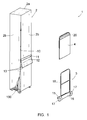
- the figures show a transport assembly 1 for a folded tent 100, or other similar bulky object, essentially comprising a cover 2, a transport device 3 and a sleeve 4.
- the tent 100 is of the kind used at events such as trade shows, sports meetings, etc., including a frame with four corner posts connected by scissors. It thus has, in the folded state, a substantially parallelepiped shape, of height of the order of 2 to 2.5 m, and relatively small ground support surface, of the order of 0.4 x 0 , 4 m.
- the cover 2 is made of a flexible material and is dimensioned so as to be engaged around the folded tent 100, without being precisely adjusted to the dimensions of this folded tent. It comprises a bottom 2a intended to come against the top of the tent, and side walls 2b sized to interrupt, when the bottom 2a rests against the top of the tent, set back from the legs of the tent poles.
- the cover 2 is equipped between two walls 2b of a zipper 10 to open it longitudinally, to allow its engagement around the tent and then close it around the latter.
- the cover 2 also includes two pieces of flexible material connected to it, about one third of its height from the ground. These pieces are arranged one against the other and are fixed to the cover 2, by seams, at the level of a part 11. They are joined to each other by seams to form a flexible intermediate portion 12, and free parts constituting flaps 13 parallel to one another, one of these flaps 13 being inside, that is to say located on the side of the cover 2, and the other being outside, that is to say located on the side opposite the cover.
- These pieces of flexible material may in particular be made of the same material as the cover 2.
- the flaps 13 comprise, on their facing faces, zones in a first self-gripping material of a system of complementary self-gripping materials.
- the transport device 3 comprises a first plate 15 intended to be engaged under the tent 100, a second plate 16 connected to the first plate 15, perpendicular to it, two wheels 17 located on either side of the plates 15 and 16 and an inverted U-shaped arch 18, forming a rigid structure which extends substantially perpendicularly to the plane of the plate 15.
- This arch 18 has a height such that its upper part is located, from the ground, substantially to the third from the height of the tent 100.
- the sheath 4 is dimensioned so as to receive in it the bow 18 in an adjusted manner. It comprises, on the opposite side to its engagement opening on the arch 18, on its two opposite walls, zones 20 made of the second self-gripping material of the system of self-gripping materials mentioned above.
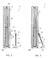
- the cover 2 is put in place on the tent 100 as shown on the figures 1 and 2 then the slider of the zipper 10 is moved to close the cover on the tent. During this operation, the transport device 3, whose hoop 18 is coated with the sleeve 4, is not connected to the cover 2 (cf. figure 2 ).
- the transport device 3 is connected to the cover 2 by removing the outer flap 13, making the connection of the zone 20 of the corresponding side of the sleeve 4 to the inner flap 13, then by folding the outer flap 13 on the zone 20 located on the other side of the sleeve 4.
- the transport device 3 is then in a pre-engagement position, visible on the figure 3 in which the arch 18 is inclined and the plate 15 is not engaged under the tent 100.
- This transport device 3 is then ideally positioned relative to the tent 100 to perform the engagement of the plate 15 under the tent 100 by simply tilting this tent.
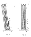
- the tent 100 is then inclined on the opposite side to that on which the transport device 3 is located, allowing the latter to pass, by simple pivoting made possible by the flexibility of the intermediate portion 12, to pass from said pre-positioned position. commitment to the commitment position shown on the figure 4 , in which the hoop 18 is disposed against the cover 2 and the plate 15 is engaged in this tent. The tent 100 is then inclined again on the side on which the transport device 3 is located in order to carry out the loading of this tent on the plate 15 (cf. figure 5 ).
- the invention provides a transport assembly 1 having, compared to the homologous assemblies of the prior art, the decisive advantages of having a perfectly easy handling and of greatly reducing the risk of a problem. spilling of the tent during this manipulation.
Landscapes
- Engineering & Computer Science (AREA)
- Chemical & Material Sciences (AREA)
- Combustion & Propulsion (AREA)
- Transportation (AREA)
- Mechanical Engineering (AREA)
- Tents Or Canopies (AREA)
Abstract
Description
- La présente invention concerne un ensemble de transport pour une tente repliée, ou autre objet volumineux similaire.
- Les tentes utilisées à l'occasion d'évènements tels que des salons professionnels, des réunions sportives, etc. doivent pouvoir être montées et démontées rapidement, ce qui implique de pouvoir les transporter facilement entre un véhicule de transport ou un lieu de stockage et le lieu de leur installation. Ces tentes ont généralement une armature à quatre poteaux de coin reliés par des ciseaux, et présentent, à l'état replié, une forme sensiblement parallélépipédique, de hauteur importante et de surface d'appui au sol relativement réduite.
- Pour le transport de telles tentes, il est connu d'utiliser divers types d'ensembles de transport comprenant des dispositifs de transport et des housses reliées à ces dispositifs. Un dispositif de transport connu comprend une plaque horizontale destinée à être engagée sous la tente repliée, une plaque verticale reliée à la housse et deux roues situées de part et d'autre de ces plaques. La housse est en un matériau souple et est dimensionnée de manière à être relativement ajustée à la tente. Elle est équipée d'une fermeture à glissières permettant de l'ouvrir longitudinalement, de sorte qu'elle est apte à être engagée autour d'une tente repliée, puis de la refermer autour de cette tente de manière à assurer le positionnement de la tente par rapport au dispositif de transport.
- La mise en place des ensembles de transport existants autour de tentes n'est pas toujours très aisée, compte tenu de la liaison du dispositif de transport à la housse et du caractère ajusté de cette housse aux dimensions de la tente. Lorsque les objets à transporter présentent des hauteurs importantes et des surfaces d'appui au sol relativement réduites, comme cela est le cas de tentes repliées, le risque existe d'un renversement de l'objet lors de la manipulation de ces ensembles de transport. Des dommages au personnel affecté au montage, démontage et transport des tentes peuvent en résulter, compte tenu du poids relativement important de ces dernières, de même que des dommages à la tente.
- Le document
KR 2003 0050377 - La présente invention vise à remédier à ces inconvénients essentiels.
- L'ensemble de transport qu'elle concerne comprend, de manière connue en soi, un dispositif de transport et une housse, le dispositif de transport comprenant une plaque destinée à être engagée sous la tente repliée et au moins une roue, et la housse étant destinée à être engagée autour de la tente.
- Selon l'invention,
- le dispositif de transport comprend une structure rigide s'étendant sensiblement perpendiculairement au plan de ladite plaque, et ayant une hauteur telle que la partie supérieure de cette structure se situe, à partir du sol, entre le quart et la moitié de la hauteur de la tente ; et
- la housse comprend des moyens de liaison à elle de la partie supérieure de cette structure rigide, permettant, lorsque cette liaison est effective, la mobilité du dispositif de transport entre une position de pré-engagement, dans laquelle la structure rigide est inclinée et ladite plaque n'est pas engagée sous la tente à transporter, et une position d'engagement, dans laquelle la structure rigide est disposée contre la housse et ladite plaque est engagée sous cette tente, lesdits moyens de liaison permettant le passage du dispositif de transport de ladite position de pré-engagement à ladite position d'engagement par pivotement du dispositif de transport par rapport à la tente, ce pivotement étant réalisé par inclinaison de cette tente.
- Ainsi, grâce à ces moyens de liaison à la housse, le dispositif de transport peut, dans ladite position de pré-engagement, être positionné de manière idéale par rapport à la tente pour réaliser l'engagement de la plaque de ce dispositif sous la tente par simple inclinaison de la tente. Cet engagement est ensuite réalisé par simple inclinaison de la tente du côté opposé à celui sur lequel se trouve le dispositif de transport ; la tente est ensuite à nouveau inclinée du côté sur lequel se trouve le dispositif de transport afin de réaliser le chargement de la tente sur la plaque que comprend ce dispositif.
- La manipulation de l'ensemble de transport selon l'invention est ainsi parfaitement aisée et le risque d'un renversement de la tente lors de la manipulation de cet ensemble de transport est très réduit.
- Lesdits moyens de liaison peuvent notamment être sous forme d'au moins une pièce de matériau souple apte à autoriser par sa déformation le pivotement du dispositif de transport entre les positions de pré-engagement et d'engagement précitées.
- De préférence, lesdits moyens de liaison sont tels que le dispositif de transport n'est pas relié de manière permanente à la housse.
- Cette dernière peut ainsi être mise en place sur la tente sans que le dispositif de transport ne soit relié à elle, ce qui rend cette mise en place très aisée. Une fois cette opération réalisée, le dispositif de transport peut être relié à la housse alors qu'il est en position de pré-engagement puis être amené en position d'engagement de la manière précitée.
- Ces moyens de liaison peuvent, dans ce cas, inclure des parties en matériaux auto-aggripants complémentaires.
- Selon une forme de réalisation préférée de l'invention,
- les moyens de liaison comprennent deux pièces de matériau souple reliées à la housse, parallèles l'un à l'autre, formant des volets dont un est intérieur, c'est-à-dire situé du côté de la housse, et l'autre est extérieur, c'est-à-dire situé du côté opposé à la housse, ces volets comportant des zones en un matériau auto-agrippant, et
- la partie supérieure de ladite structure rigide comprend, sur deux côtés opposés, des zones en matériau auto-agrippant complémentaire de celui des volets,
- Un positionnement précis du dispositif de transport par rapport à la housse, et une parfaite liaison de ce dispositif de transport à la housse, sont ainsi obtenus.
- Ladite structure rigide peut notamment se présenter sous la forme d'un arceau en forme de U inversé ; dans ce cas, l'ensemble de transport comprend avantageusement un fourreau ajusté à cet arceau, comportant, sur deux parois opposées, lesdites zones en matériau auto-agrippant, ce fourreau pouvant être engagé de manière ajustée sur l'arceau afin de réaliser l'assemblage à l'arceau desdites zones en matériau auto- agrippant.
- Ce fourreau a également pour avantage de permettre une protection de l'arceau.
- Avantageusement, l'ensemble de transport comprend des moyens permettant d'empêcher le retour du dispositif de transport en position de pré-engagement après que ce dispositif de transport ait été amené en position d'engagement.
- Ces moyens d'empêchement permettent de sécuriser l'opération de chargement de la tente.
- Ils peuvent notamment être sous forme d'une ou plusieurs sangles destinées à entourer la housse et ladite structure rigide du dispositif de transport.
- L'invention sera bien comprise, et d'autres caractéristiques et avantages de celle-ci apparaîtront, en référence au dessin schématique annexé, représentant, à titre d'exemple non limitatif, une forme de réalisation préférée de l'ensemble de transport qu'elle concerne.
- La
figure 1 est une vue en perspective éclatée d'une housse, d'un dispositif de transport et d'un fourreau qu'il comprend, la housse étant engagée sur une tente repliée ; et - les
figures 2 à 5 en sont des vues de côté, en coupe longitudinale de la housse, au cours de quatre étapes successives de chargement de la housse sur le dispositif de transport. - Les figures représentent un ensemble de transport 1 pour une tente repliée 100, ou autre objet volumineux similaire, comprenant essentiellement une housse 2, un dispositif de transport 3 et un fourreau 4.
- La tente 100 est du genre de celles utilisées à l'occasion d'évènements tels que des salons professionnels, des réunions sportives, etc., comprenant une armature à quatre poteaux de coin reliés par des ciseaux. Elle présente ainsi, à l'état replié, une forme sensiblement parallélépipédique, de hauteur de l'ordre de 2 à 2,5 m, et de surface d'appui au sol relativement réduite, de l'ordre de 0,4 x 0,4 m.
- La housse 2 est en un matériau souple et est dimensionnée de manière à être engagée autour de la tente repliée 100, sans être précisément ajustée aux dimensions de cette tente repliée. Elle comprend un fond 2a destiné à venir contre le sommet de la tente, et des parois latérales 2b dimensionnées pour s'interrompre, lorsque le fond 2a repose contre le sommet de la tente, en retrait des pieds des poteaux de la tente.
- La housse 2 est équipée entre deux parois 2b d'une fermeture à glissières 10 permettant de l'ouvrir longitudinalement, afin de permettre son engagement autour de la tente puis de la refermer autour de cette dernière.
- La housse 2 comprend également deux pièces de matériau souple reliées à elle, environ au tiers de sa hauteur à partir du sol. Ces pièces sont disposées l'une contre l'autre et sont fixées à la housse 2, par des coutures, au niveau d'une partie de base 11. Elles sont réunies l'une à l'autre par des coutures permettant de former une partie intermédiaire souple 12, et des parties libres constituant des volets 13 parallèles l'un à l'autre, l'un de ces volets 13 étant intérieur, c'est-à-dire situé du côté de la housse 2, et l'autre étant extérieur, c'est-à-dire situé du côté opposé à la housse.
- Ces pièces de matériau souple peuvent notamment être réalisées dans le même matériau que la housse 2.
- Les volets 13 comportent, sur leurs faces en regard, des zones en un premier matériau auto-agrippant d'un système de matériaux auto-agrippants complémentaires.
- Le dispositif de transport 3 comprend une première plaque 15 destinée à être engagée sous la tente 100, une deuxième plaque 16 reliée à la première plaque 15, perpendiculairement à celle-ci, deux roues 17 situées de part et d'autre des plaques 15 et 16 et un arceau 18 en forme de U inversé, formant une structure rigide qui s'étend sensiblement perpendiculairement au plan de la plaque 15. Cet arceau 18 a une hauteur telle que sa partie supérieure se situe, à partir du sol, sensiblement au tiers de la hauteur de la tente 100.
- Le fourreau 4 est dimensionné de façon à pouvoir recevoir en lui l'arceau 18 de manière ajustée. Il comporte, du côté opposé à son ouverture d'engagement sur l'arceau 18, sur ses deux parois opposées, des zones 20 faites du deuxième matériau auto-agrippant du système de matériaux auto-agrippants précité.
- En pratique, la housse 2 est mise en place sur la tente 100 comme montré sur les
figures 1 et2 puis le curseur de la fermeture à glissières 10 est déplacé pour réaliser la fermeture de cette housse sur la tente. Lors de cette opération, le dispositif de transport 3, dont l'arceau 18 est revêtu du fourreau 4, n'est pas relié à la housse 2 (cf.figure 2 ). - Une fois la housse 2 en place sur la tente 100, le dispositif de transport 3 est relié à la housse 2 en écartant le volet 13 extérieur, en réalisant la liaison de la zone 20 du côté correspondant du fourreau 4 au volet 13 intérieur, puis en rabattant le volet 13 extérieur sur la zone 20 située de l'autre côté du fourreau 4. Le dispositif de transport 3 se trouve alors dans une position de pré-engagement, visible sur la
figure 3 , dans laquelle l'arceau 18 est incliné et la plaque 15 n'est pas engagée sous la tente 100. Ce dispositif de transport 3 est alors positionné de manière idéale par rapport à la tente 100 pour réaliser l'engagement de la plaque 15 sous la tente 100 par simple inclinaison de cette tente. - La tente 100 est ensuite inclinée du côté opposé à celui sur lequel se trouve le dispositif de transport 3, permettant à ce dernier de passer, par simple pivotement rendu possible par la souplesse de la partie intermédiaire 12, de passer de ladite position de pré-engagement à la position d'engagement montrée sur la
figure 4 , dans laquelle l'arceau 18 est disposé contre la housse 2 et la plaque 15 est engagée sous cette tente. La tente 100 est ensuite à nouveau inclinée du côté sur lequel se trouve le dispositif de transport 3 afin de réaliser le chargement de cette tente sur la plaque 15 (cf.figure 5 ). - Ainsi que cela apparaît de ce qui précède, l'invention fournit un ensemble de transport 1 présentant, par rapport aux ensembles homologues de la technique antérieure, les avantages déterminants d'avoir une manipulation parfaitement aisée et de réduire très fortement le risque d'un renversement de la tente lors de cette manipulation.
- L'invention a été décrite ci-dessus en référence à une forme de réalisation fournie à titre d'exemple. Il va de soi qu'elle n'est pas limitée à cette forme de réalisation mais qu'elle s'étend à toutes les autres formes de réalisations couvertes par les revendications ci-annexées.
Claims (8)
caractérisé en ce que :
Applications Claiming Priority (1)
| Application Number | Priority Date | Filing Date | Title |
|---|---|---|---|
| FR0900800A FR2942443A1 (fr) | 2009-02-23 | 2009-02-23 | Ensemble de transport pour une tente repliee, ou autre objet volumineux similaire |
Publications (2)
| Publication Number | Publication Date |
|---|---|
| EP2221229A1 true EP2221229A1 (fr) | 2010-08-25 |
| EP2221229B1 EP2221229B1 (fr) | 2012-05-16 |
Family
ID=41213294
Family Applications (1)
| Application Number | Title | Priority Date | Filing Date |
|---|---|---|---|
| EP20100153779 Not-in-force EP2221229B1 (fr) | 2009-02-23 | 2010-02-17 | Ensemble de transport pour une tente repliée, ou autre objet volumineux similaire |
Country Status (2)
| Country | Link |
|---|---|
| EP (1) | EP2221229B1 (fr) |
| FR (1) | FR2942443A1 (fr) |
Cited By (2)
| Publication number | Priority date | Publication date | Assignee | Title |
|---|---|---|---|---|
| EP2662513A1 (fr) * | 2012-05-08 | 2013-11-13 | Expotrade Group GmbH | Elément de transport, en particulier pour un système de tente, ainsi que le système de tente |
| US11225276B2 (en) * | 2019-04-16 | 2022-01-18 | Eurmax Canopy Inc | Folding structure rolling bag |
Citations (7)
| Publication number | Priority date | Publication date | Assignee | Title |
|---|---|---|---|---|
| GB2278318A (en) * | 1993-05-27 | 1994-11-30 | Arlin Landis Kriebel | Crate moving trolley |
| WO2002008043A1 (fr) * | 2000-07-26 | 2002-01-31 | Carter Mark C | Plate-forme a roues pour abri a auvent montable |
| KR20030050377A (ko) | 2001-12-18 | 2003-06-25 | 유지호 | 절첩식 운반수레 |
| EP1426265A2 (fr) * | 2002-12-05 | 2004-06-09 | Heinz Stöckler | Emballage avec dispositif de transport pour tente pliée |
| US20040188963A1 (en) * | 2002-10-21 | 2004-09-30 | Heather Gant | Wheeled bag carrier and equipment bag |
| US7219902B1 (en) * | 1996-10-21 | 2007-05-22 | West Coast Trends, Inc. | Flexible travel bag with integrated support to protect bag from wear |
| FR2913655A1 (fr) * | 2007-03-12 | 2008-09-19 | Carlo Robba | Chariot de transport de tentes |
-
2009
- 2009-02-23 FR FR0900800A patent/FR2942443A1/fr not_active Withdrawn
-
2010
- 2010-02-17 EP EP20100153779 patent/EP2221229B1/fr not_active Not-in-force
Patent Citations (7)
| Publication number | Priority date | Publication date | Assignee | Title |
|---|---|---|---|---|
| GB2278318A (en) * | 1993-05-27 | 1994-11-30 | Arlin Landis Kriebel | Crate moving trolley |
| US7219902B1 (en) * | 1996-10-21 | 2007-05-22 | West Coast Trends, Inc. | Flexible travel bag with integrated support to protect bag from wear |
| WO2002008043A1 (fr) * | 2000-07-26 | 2002-01-31 | Carter Mark C | Plate-forme a roues pour abri a auvent montable |
| KR20030050377A (ko) | 2001-12-18 | 2003-06-25 | 유지호 | 절첩식 운반수레 |
| US20040188963A1 (en) * | 2002-10-21 | 2004-09-30 | Heather Gant | Wheeled bag carrier and equipment bag |
| EP1426265A2 (fr) * | 2002-12-05 | 2004-06-09 | Heinz Stöckler | Emballage avec dispositif de transport pour tente pliée |
| FR2913655A1 (fr) * | 2007-03-12 | 2008-09-19 | Carlo Robba | Chariot de transport de tentes |
Cited By (3)
| Publication number | Priority date | Publication date | Assignee | Title |
|---|---|---|---|---|
| EP2662513A1 (fr) * | 2012-05-08 | 2013-11-13 | Expotrade Group GmbH | Elément de transport, en particulier pour un système de tente, ainsi que le système de tente |
| WO2013167392A1 (fr) * | 2012-05-08 | 2013-11-14 | Expotrade Group Gmbh | Élément de translation, en particulier élément de translation pour système de tente, et système de tente |
| US11225276B2 (en) * | 2019-04-16 | 2022-01-18 | Eurmax Canopy Inc | Folding structure rolling bag |
Also Published As
| Publication number | Publication date |
|---|---|
| FR2942443A1 (fr) | 2010-08-27 |
| EP2221229B1 (fr) | 2012-05-16 |
Similar Documents
| Publication | Publication Date | Title |
|---|---|---|
| FR2760730A1 (fr) | Conteneur repliable a rangement alveolaire, notamment pour le transport de pieces de monte pour l'industrie automobile | |
| EP2221229B1 (fr) | Ensemble de transport pour une tente repliée, ou autre objet volumineux similaire | |
| FR2848187A1 (fr) | Chariot de transport de marchandises comportant au moins un volet anti chute | |
| EP0912409B1 (fr) | Dispositif pour le stockage et le transport d'elements allonges tels que des pare-chocs | |
| FR2859358A1 (fr) | Ensemble formant bagage a roulettes | |
| FR2732938A1 (fr) | Combinaison d'un chariot et d'un element amovible et element amovible pour chariot | |
| WO2001062574A1 (fr) | Panier pour chariot de magasin en libre service | |
| FR2883558A1 (fr) | Conteneur de reception d'articles et son support coulissant | |
| EP0857448B1 (fr) | Grille de cuisson à panneaux articulés | |
| FR3086253A1 (fr) | Module logistique pliable | |
| FR2913655A1 (fr) | Chariot de transport de tentes | |
| EP0279999B1 (fr) | Support de caisse pour chariot de transport, et chariot equipe d'un tel support | |
| FR2581933A1 (fr) | Chariot de transport, notamment pour la clientele de magasins a libre-service. | |
| FR2827262A1 (fr) | Conteneur isotherme demontable | |
| EP1813542B1 (fr) | Conteneur muni de tés de gerbage articulés | |
| FR2708464A1 (fr) | Chariot-brancard comprenant un bâti et un brancard fixe de manière démontable sur le bâti. | |
| FR2620400A1 (fr) | Chariot transporteur et convoyeur | |
| FR2561601A1 (fr) | Chariot de type " diable " pour le transport d'objets tels que des valises | |
| FR2590964A1 (fr) | Piece d'articulation, notamment pour cloison intermediaire d'un chariot de magasin a libre-service | |
| EP4051535B1 (fr) | Véhicule automobile doté de caissons de stockage | |
| FR2879080A1 (fr) | Sac de transport de marchandises | |
| FR2589830A1 (fr) | Sangle pour chariots de transport de marchandises | |
| FR2591872A1 (fr) | Sangle a roulettes | |
| FR2751618A1 (fr) | Casier demontable pour le transport et/ou le stockage d'objets divers, notamment de bouteilles | |
| FR3046429A1 (fr) | Abri stationnaire de stockage d'au moins une unite de stockage d'energie electrique |
Legal Events
| Date | Code | Title | Description |
|---|---|---|---|
| PUAI | Public reference made under article 153(3) epc to a published international application that has entered the european phase |
Free format text: ORIGINAL CODE: 0009012 |
|
| AK | Designated contracting states |
Kind code of ref document: A1 Designated state(s): AT BE BG CH CY CZ DE DK EE ES FI FR GB GR HR HU IE IS IT LI LT LU LV MC MK MT NL NO PL PT RO SE SI SK SM TR |
|
| AX | Request for extension of the european patent |
Extension state: AL BA RS |
|
| 17P | Request for examination filed |
Effective date: 20101203 |
|
| GRAP | Despatch of communication of intention to grant a patent |
Free format text: ORIGINAL CODE: EPIDOSNIGR1 |
|
| RIC1 | Information provided on ipc code assigned before grant |
Ipc: B62B 1/14 20060101AFI20111104BHEP |
|
| GRAS | Grant fee paid |
Free format text: ORIGINAL CODE: EPIDOSNIGR3 |
|
| GRAA | (expected) grant |
Free format text: ORIGINAL CODE: 0009210 |
|
| AK | Designated contracting states |
Kind code of ref document: B1 Designated state(s): AT BE BG CH CY CZ DE DK EE ES FI FR GB GR HR HU IE IS IT LI LT LU LV MC MK MT NL NO PL PT RO SE SI SK SM TR |
|
| REG | Reference to a national code |
Ref country code: GB Ref legal event code: FG4D Free format text: NOT ENGLISH |
|
| REG | Reference to a national code |
Ref country code: CH Ref legal event code: EP |
|
| REG | Reference to a national code |
Ref country code: AT Ref legal event code: REF Ref document number: 557943 Country of ref document: AT Kind code of ref document: T Effective date: 20120615 |
|
| REG | Reference to a national code |
Ref country code: IE Ref legal event code: FG4D Free format text: LANGUAGE OF EP DOCUMENT: FRENCH |
|
| REG | Reference to a national code |
Ref country code: DE Ref legal event code: R096 Ref document number: 602010001550 Country of ref document: DE Effective date: 20120712 |
|
| REG | Reference to a national code |
Ref country code: NL Ref legal event code: VDEP Effective date: 20120516 |
|
| REG | Reference to a national code |
Ref country code: LT Ref legal event code: MG4D Effective date: 20120516 |
|
| PG25 | Lapsed in a contracting state [announced via postgrant information from national office to epo] |
Ref country code: PL Free format text: LAPSE BECAUSE OF FAILURE TO SUBMIT A TRANSLATION OF THE DESCRIPTION OR TO PAY THE FEE WITHIN THE PRESCRIBED TIME-LIMIT Effective date: 20120516 Ref country code: FI Free format text: LAPSE BECAUSE OF FAILURE TO SUBMIT A TRANSLATION OF THE DESCRIPTION OR TO PAY THE FEE WITHIN THE PRESCRIBED TIME-LIMIT Effective date: 20120516 Ref country code: CY Free format text: LAPSE BECAUSE OF FAILURE TO SUBMIT A TRANSLATION OF THE DESCRIPTION OR TO PAY THE FEE WITHIN THE PRESCRIBED TIME-LIMIT Effective date: 20120516 Ref country code: NO Free format text: LAPSE BECAUSE OF FAILURE TO SUBMIT A TRANSLATION OF THE DESCRIPTION OR TO PAY THE FEE WITHIN THE PRESCRIBED TIME-LIMIT Effective date: 20120816 Ref country code: LT Free format text: LAPSE BECAUSE OF FAILURE TO SUBMIT A TRANSLATION OF THE DESCRIPTION OR TO PAY THE FEE WITHIN THE PRESCRIBED TIME-LIMIT Effective date: 20120516 Ref country code: IS Free format text: LAPSE BECAUSE OF FAILURE TO SUBMIT A TRANSLATION OF THE DESCRIPTION OR TO PAY THE FEE WITHIN THE PRESCRIBED TIME-LIMIT Effective date: 20120916 Ref country code: SE Free format text: LAPSE BECAUSE OF FAILURE TO SUBMIT A TRANSLATION OF THE DESCRIPTION OR TO PAY THE FEE WITHIN THE PRESCRIBED TIME-LIMIT Effective date: 20120516 |
|
| REG | Reference to a national code |
Ref country code: AT Ref legal event code: MK05 Ref document number: 557943 Country of ref document: AT Kind code of ref document: T Effective date: 20120516 |
|
| PG25 | Lapsed in a contracting state [announced via postgrant information from national office to epo] |
Ref country code: HR Free format text: LAPSE BECAUSE OF FAILURE TO SUBMIT A TRANSLATION OF THE DESCRIPTION OR TO PAY THE FEE WITHIN THE PRESCRIBED TIME-LIMIT Effective date: 20120516 Ref country code: SI Free format text: LAPSE BECAUSE OF FAILURE TO SUBMIT A TRANSLATION OF THE DESCRIPTION OR TO PAY THE FEE WITHIN THE PRESCRIBED TIME-LIMIT Effective date: 20120516 Ref country code: LV Free format text: LAPSE BECAUSE OF FAILURE TO SUBMIT A TRANSLATION OF THE DESCRIPTION OR TO PAY THE FEE WITHIN THE PRESCRIBED TIME-LIMIT Effective date: 20120516 Ref country code: PT Free format text: LAPSE BECAUSE OF FAILURE TO SUBMIT A TRANSLATION OF THE DESCRIPTION OR TO PAY THE FEE WITHIN THE PRESCRIBED TIME-LIMIT Effective date: 20120917 Ref country code: GR Free format text: LAPSE BECAUSE OF FAILURE TO SUBMIT A TRANSLATION OF THE DESCRIPTION OR TO PAY THE FEE WITHIN THE PRESCRIBED TIME-LIMIT Effective date: 20120817 |
|
| PG25 | Lapsed in a contracting state [announced via postgrant information from national office to epo] |
Ref country code: SK Free format text: LAPSE BECAUSE OF FAILURE TO SUBMIT A TRANSLATION OF THE DESCRIPTION OR TO PAY THE FEE WITHIN THE PRESCRIBED TIME-LIMIT Effective date: 20120516 Ref country code: EE Free format text: LAPSE BECAUSE OF FAILURE TO SUBMIT A TRANSLATION OF THE DESCRIPTION OR TO PAY THE FEE WITHIN THE PRESCRIBED TIME-LIMIT Effective date: 20120516 Ref country code: DK Free format text: LAPSE BECAUSE OF FAILURE TO SUBMIT A TRANSLATION OF THE DESCRIPTION OR TO PAY THE FEE WITHIN THE PRESCRIBED TIME-LIMIT Effective date: 20120516 Ref country code: CZ Free format text: LAPSE BECAUSE OF FAILURE TO SUBMIT A TRANSLATION OF THE DESCRIPTION OR TO PAY THE FEE WITHIN THE PRESCRIBED TIME-LIMIT Effective date: 20120516 Ref country code: RO Free format text: LAPSE BECAUSE OF FAILURE TO SUBMIT A TRANSLATION OF THE DESCRIPTION OR TO PAY THE FEE WITHIN THE PRESCRIBED TIME-LIMIT Effective date: 20120516 Ref country code: AT Free format text: LAPSE BECAUSE OF FAILURE TO SUBMIT A TRANSLATION OF THE DESCRIPTION OR TO PAY THE FEE WITHIN THE PRESCRIBED TIME-LIMIT Effective date: 20120516 Ref country code: NL Free format text: LAPSE BECAUSE OF FAILURE TO SUBMIT A TRANSLATION OF THE DESCRIPTION OR TO PAY THE FEE WITHIN THE PRESCRIBED TIME-LIMIT Effective date: 20120516 |
|
| PG25 | Lapsed in a contracting state [announced via postgrant information from national office to epo] |
Ref country code: IT Free format text: LAPSE BECAUSE OF FAILURE TO SUBMIT A TRANSLATION OF THE DESCRIPTION OR TO PAY THE FEE WITHIN THE PRESCRIBED TIME-LIMIT Effective date: 20120516 |
|
| PLBE | No opposition filed within time limit |
Free format text: ORIGINAL CODE: 0009261 |
|
| STAA | Information on the status of an ep patent application or granted ep patent |
Free format text: STATUS: NO OPPOSITION FILED WITHIN TIME LIMIT |
|
| 26N | No opposition filed |
Effective date: 20130219 |
|
| PG25 | Lapsed in a contracting state [announced via postgrant information from national office to epo] |
Ref country code: ES Free format text: LAPSE BECAUSE OF FAILURE TO SUBMIT A TRANSLATION OF THE DESCRIPTION OR TO PAY THE FEE WITHIN THE PRESCRIBED TIME-LIMIT Effective date: 20120827 |
|
| PGFP | Annual fee paid to national office [announced via postgrant information from national office to epo] |
Ref country code: DE Payment date: 20130311 Year of fee payment: 4 Ref country code: FR Payment date: 20130322 Year of fee payment: 4 |
|
| REG | Reference to a national code |
Ref country code: DE Ref legal event code: R097 Ref document number: 602010001550 Country of ref document: DE Effective date: 20130219 |
|
| PG25 | Lapsed in a contracting state [announced via postgrant information from national office to epo] |
Ref country code: BG Free format text: LAPSE BECAUSE OF FAILURE TO SUBMIT A TRANSLATION OF THE DESCRIPTION OR TO PAY THE FEE WITHIN THE PRESCRIBED TIME-LIMIT Effective date: 20120816 |
|
| PGFP | Annual fee paid to national office [announced via postgrant information from national office to epo] |
Ref country code: BE Payment date: 20130327 Year of fee payment: 4 |
|
| PG25 | Lapsed in a contracting state [announced via postgrant information from national office to epo] |
Ref country code: MC Free format text: LAPSE BECAUSE OF NON-PAYMENT OF DUE FEES Effective date: 20130228 |
|
| REG | Reference to a national code |
Ref country code: IE Ref legal event code: MM4A |
|
| PG25 | Lapsed in a contracting state [announced via postgrant information from national office to epo] |
Ref country code: IE Free format text: LAPSE BECAUSE OF NON-PAYMENT OF DUE FEES Effective date: 20130217 |
|
| PG25 | Lapsed in a contracting state [announced via postgrant information from national office to epo] |
Ref country code: MT Free format text: LAPSE BECAUSE OF FAILURE TO SUBMIT A TRANSLATION OF THE DESCRIPTION OR TO PAY THE FEE WITHIN THE PRESCRIBED TIME-LIMIT Effective date: 20120516 |
|
| BERE | Be: lapsed |
Owner name: LP TENT SARL Effective date: 20140228 |
|
| REG | Reference to a national code |
Ref country code: DE Ref legal event code: R119 Ref document number: 602010001550 Country of ref document: DE |
|
| REG | Reference to a national code |
Ref country code: CH Ref legal event code: PL |
|
| GBPC | Gb: european patent ceased through non-payment of renewal fee |
Effective date: 20140217 |
|
| PG25 | Lapsed in a contracting state [announced via postgrant information from national office to epo] |
Ref country code: LI Free format text: LAPSE BECAUSE OF NON-PAYMENT OF DUE FEES Effective date: 20140228 Ref country code: CH Free format text: LAPSE BECAUSE OF NON-PAYMENT OF DUE FEES Effective date: 20140228 |
|
| REG | Reference to a national code |
Ref country code: FR Ref legal event code: ST Effective date: 20141031 |
|
| REG | Reference to a national code |
Ref country code: DE Ref legal event code: R119 Ref document number: 602010001550 Country of ref document: DE Effective date: 20140902 |
|
| PG25 | Lapsed in a contracting state [announced via postgrant information from national office to epo] |
Ref country code: FR Free format text: LAPSE BECAUSE OF NON-PAYMENT OF DUE FEES Effective date: 20140228 Ref country code: GB Free format text: LAPSE BECAUSE OF NON-PAYMENT OF DUE FEES Effective date: 20140217 Ref country code: BE Free format text: LAPSE BECAUSE OF NON-PAYMENT OF DUE FEES Effective date: 20140228 Ref country code: DE Free format text: LAPSE BECAUSE OF NON-PAYMENT OF DUE FEES Effective date: 20140902 |
|
| PG25 | Lapsed in a contracting state [announced via postgrant information from national office to epo] |
Ref country code: SM Free format text: LAPSE BECAUSE OF FAILURE TO SUBMIT A TRANSLATION OF THE DESCRIPTION OR TO PAY THE FEE WITHIN THE PRESCRIBED TIME-LIMIT Effective date: 20120516 |
|
| PG25 | Lapsed in a contracting state [announced via postgrant information from national office to epo] |
Ref country code: TR Free format text: LAPSE BECAUSE OF FAILURE TO SUBMIT A TRANSLATION OF THE DESCRIPTION OR TO PAY THE FEE WITHIN THE PRESCRIBED TIME-LIMIT Effective date: 20120516 |
|
| PG25 | Lapsed in a contracting state [announced via postgrant information from national office to epo] |
Ref country code: LU Free format text: LAPSE BECAUSE OF NON-PAYMENT OF DUE FEES Effective date: 20130217 Ref country code: MK Free format text: LAPSE BECAUSE OF FAILURE TO SUBMIT A TRANSLATION OF THE DESCRIPTION OR TO PAY THE FEE WITHIN THE PRESCRIBED TIME-LIMIT Effective date: 20120516 Ref country code: HU Free format text: LAPSE BECAUSE OF FAILURE TO SUBMIT A TRANSLATION OF THE DESCRIPTION OR TO PAY THE FEE WITHIN THE PRESCRIBED TIME-LIMIT; INVALID AB INITIO Effective date: 20100217 |