EP2221132B2 - Production device and production method of metal powder sintered component - Google Patents
Production device and production method of metal powder sintered component Download PDFInfo
- Publication number
- EP2221132B2 EP2221132B2 EP08842800.8A EP08842800A EP2221132B2 EP 2221132 B2 EP2221132 B2 EP 2221132B2 EP 08842800 A EP08842800 A EP 08842800A EP 2221132 B2 EP2221132 B2 EP 2221132B2
- Authority
- EP
- European Patent Office
- Prior art keywords
- light beams
- irradiation
- scan head
- shaped object
- formation
- Prior art date
- Legal status (The legal status is an assumption and is not a legal conclusion. Google has not performed a legal analysis and makes no representation as to the accuracy of the status listed.)
- Not-in-force
Links
- 239000000843 powder Substances 0.000 title claims description 73
- 238000004519 manufacturing process Methods 0.000 title claims description 57
- 239000002184 metal Substances 0.000 title claims description 29
- 230000015572 biosynthetic process Effects 0.000 claims description 92
- 239000010410 layer Substances 0.000 claims description 70
- 238000003801 milling Methods 0.000 claims description 28
- 238000005520 cutting process Methods 0.000 claims description 22
- 239000000758 substrate Substances 0.000 claims description 10
- 238000000034 method Methods 0.000 claims description 8
- 230000008569 process Effects 0.000 claims description 8
- 239000002344 surface layer Substances 0.000 claims description 4
- 230000003287 optical effect Effects 0.000 description 12
- 239000000463 material Substances 0.000 description 10
- 238000003754 machining Methods 0.000 description 8
- 238000005245 sintering Methods 0.000 description 7
- 230000005855 radiation Effects 0.000 description 4
- 230000003247 decreasing effect Effects 0.000 description 3
- 239000011261 inert gas Substances 0.000 description 3
- 230000001678 irradiating effect Effects 0.000 description 3
- CURLTUGMZLYLDI-UHFFFAOYSA-N Carbon dioxide Chemical compound O=C=O CURLTUGMZLYLDI-UHFFFAOYSA-N 0.000 description 2
- 230000000694 effects Effects 0.000 description 2
- 230000002708 enhancing effect Effects 0.000 description 2
- 230000007246 mechanism Effects 0.000 description 2
- 239000013307 optical fiber Substances 0.000 description 2
- IJGRMHOSHXDMSA-UHFFFAOYSA-N Atomic nitrogen Chemical compound N#N IJGRMHOSHXDMSA-UHFFFAOYSA-N 0.000 description 1
- 240000001973 Ficus microcarpa Species 0.000 description 1
- 238000000149 argon plasma sintering Methods 0.000 description 1
- QVGXLLKOCUKJST-UHFFFAOYSA-N atomic oxygen Chemical compound [O] QVGXLLKOCUKJST-UHFFFAOYSA-N 0.000 description 1
- 229910002092 carbon dioxide Inorganic materials 0.000 description 1
- 239000001569 carbon dioxide Substances 0.000 description 1
- 230000008859 change Effects 0.000 description 1
- 238000010276 construction Methods 0.000 description 1
- 229910001873 dinitrogen Inorganic materials 0.000 description 1
- 239000000835 fiber Substances 0.000 description 1
- 238000002372 labelling Methods 0.000 description 1
- 239000007788 liquid Substances 0.000 description 1
- 230000004048 modification Effects 0.000 description 1
- 238000012986 modification Methods 0.000 description 1
- 230000003647 oxidation Effects 0.000 description 1
- 238000007254 oxidation reaction Methods 0.000 description 1
- 239000001301 oxygen Substances 0.000 description 1
- 229910052760 oxygen Inorganic materials 0.000 description 1
- 239000006072 paste Substances 0.000 description 1
- 230000009467 reduction Effects 0.000 description 1
Images


Classifications
-
- B—PERFORMING OPERATIONS; TRANSPORTING
- B22—CASTING; POWDER METALLURGY
- B22F—WORKING METALLIC POWDER; MANUFACTURE OF ARTICLES FROM METALLIC POWDER; MAKING METALLIC POWDER; APPARATUS OR DEVICES SPECIALLY ADAPTED FOR METALLIC POWDER
- B22F12/00—Apparatus or devices specially adapted for additive manufacturing; Auxiliary means for additive manufacturing; Combinations of additive manufacturing apparatus or devices with other processing apparatus or devices
-
- B—PERFORMING OPERATIONS; TRANSPORTING
- B22—CASTING; POWDER METALLURGY
- B22F—WORKING METALLIC POWDER; MANUFACTURE OF ARTICLES FROM METALLIC POWDER; MAKING METALLIC POWDER; APPARATUS OR DEVICES SPECIALLY ADAPTED FOR METALLIC POWDER
- B22F10/00—Additive manufacturing of workpieces or articles from metallic powder
- B22F10/20—Direct sintering or melting
- B22F10/28—Powder bed fusion, e.g. selective laser melting [SLM] or electron beam melting [EBM]
-
- B—PERFORMING OPERATIONS; TRANSPORTING
- B22—CASTING; POWDER METALLURGY
- B22F—WORKING METALLIC POWDER; MANUFACTURE OF ARTICLES FROM METALLIC POWDER; MAKING METALLIC POWDER; APPARATUS OR DEVICES SPECIALLY ADAPTED FOR METALLIC POWDER
- B22F12/00—Apparatus or devices specially adapted for additive manufacturing; Auxiliary means for additive manufacturing; Combinations of additive manufacturing apparatus or devices with other processing apparatus or devices
- B22F12/22—Driving means
- B22F12/222—Driving means for motion along a direction orthogonal to the plane of a layer
-
- B—PERFORMING OPERATIONS; TRANSPORTING
- B22—CASTING; POWDER METALLURGY
- B22F—WORKING METALLIC POWDER; MANUFACTURE OF ARTICLES FROM METALLIC POWDER; MAKING METALLIC POWDER; APPARATUS OR DEVICES SPECIALLY ADAPTED FOR METALLIC POWDER
- B22F12/00—Apparatus or devices specially adapted for additive manufacturing; Auxiliary means for additive manufacturing; Combinations of additive manufacturing apparatus or devices with other processing apparatus or devices
- B22F12/22—Driving means
- B22F12/224—Driving means for motion along a direction within the plane of a layer
-
- B—PERFORMING OPERATIONS; TRANSPORTING
- B22—CASTING; POWDER METALLURGY
- B22F—WORKING METALLIC POWDER; MANUFACTURE OF ARTICLES FROM METALLIC POWDER; MAKING METALLIC POWDER; APPARATUS OR DEVICES SPECIALLY ADAPTED FOR METALLIC POWDER
- B22F12/00—Apparatus or devices specially adapted for additive manufacturing; Auxiliary means for additive manufacturing; Combinations of additive manufacturing apparatus or devices with other processing apparatus or devices
- B22F12/22—Driving means
- B22F12/226—Driving means for rotary motion
-
- Y—GENERAL TAGGING OF NEW TECHNOLOGICAL DEVELOPMENTS; GENERAL TAGGING OF CROSS-SECTIONAL TECHNOLOGIES SPANNING OVER SEVERAL SECTIONS OF THE IPC; TECHNICAL SUBJECTS COVERED BY FORMER USPC CROSS-REFERENCE ART COLLECTIONS [XRACs] AND DIGESTS
- Y02—TECHNOLOGIES OR APPLICATIONS FOR MITIGATION OR ADAPTATION AGAINST CLIMATE CHANGE
- Y02P—CLIMATE CHANGE MITIGATION TECHNOLOGIES IN THE PRODUCTION OR PROCESSING OF GOODS
- Y02P10/00—Technologies related to metal processing
- Y02P10/25—Process efficiency
Definitions
- the present invention relates to manufacturing equipment and manufacturing methods for forming a metal powder sintered component by irradiating metal powder with light beams.
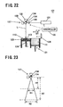
- FIG. 22 shows a configuration of the manufacturing equipment.
- the manufacturing equipment 101 comprises a material tank 121 that supplies metal powder 111, a substrate 123 on which a powder layer 112 is placed, a formation table 124 that holds the substrate 123 and moves up and down, a wiper 126 that spreads the metal powder 111 contained in the material tank 121 onto the substrate 123, a light beam oscillator 131 that emits light beams L, a scan head 137 that directs light beams L emitted from the light beam oscillator 131 onto the powder layer 112 for scanning, and a controller 105 that controls the operation of the manufacturing equipment 101.
- the scan head 137 comprises a condenser lens 138 that collects light beams L, two rotatable scan mirrors 134 that reflect light beams L, and a scanner 135 that controls the rotation angles of the scan mirrors 134.
- the controller 105 causes the light beam oscillator 131 to emit light beams L and collects the emitted light beams L by the condenser lens 138. Then, the controller 105 causes the scanner 135 to rotate the scan mirrors 134 so that the scan mirrors 134 reflect the collected light beams L onto the powder layer 112 to sinter the metal powder 111 and thus form a sintered layer 113.
- FIG. 23 shows the relationship between the irradiation height and the irradiated area.
- the irradiation height is changed from a height H1 to a height H2
- the irradiated area increases from an irradiated area R1 to an irradiated area R2.
- the accuracy of light beam L scanning is reduced because the irradiation position is changed significantly by slight rotation of the scan mirrors 134.
- FIG. 24 shows a configuration of the manufacturing equipment.
- the manufacturing equipment 201 comprises a light beam oscillator 231 that emits light beams L, two mirrors, an X-reflection mirror 232 and a Y-reflection mirror 233, that reflect light beams L, an optical component 234 that focuses reflected light beams L, a formation tank 225 where a powder layer 212 is placed, an X-movement shaft 235 that moves the X-refection mirror 232 in the X direction, and a Y-movement shaft 236 that moves the Y-reflection mirror 233 in the Y direction.
- Light beams L emitted from the light beam oscillator 231 are reflected by the X-reflection mirror 232 and the Y-reflection mirror 233, focused on the powder layer 212 by the optical component 234, and directed over the powder layer 212 for scanning by the X-movement shaft 235 and the Y-movement shaft 236.
- FIG. 25 shows the relationship between the irradiation angle of light beams L from the light beam oscillator 231 and the error in irradiation position. Since light beams L are large in optical axis length, even a slight deviation of the irradiation angle of light beams L from the light beam oscillator 231 causes a large error in irradiation position.
- FIG. 26 shows the relationship between the deviation of the optical axis of a light beam L from the moving direction of the X-reflection mirror 232 and the error in irradiation position.
- a slight deviation of the optical axis of the light beam L from the moving direction of the X-reflection mirror 232 causes a larger error in irradiation position as the travel distance becomes longer.
- a deviation of the optical axis of the light beam L from the moving direction of the Y-reflection mirror 233 also causes a large error in irradiation position.
- Manufacturing equipment in which a light beam oscillator and a scan head for directing light beams move in a single direction parallel to a powder layer for light beam scanning (see, for example, JP 2004-122489 A ).
- EP 1 661 657 A1 discloses a laser processing robot system including a manipulator, a laser processing tool attached to the manipulator, and a control unit for controlling operations of the manipulator and the laser processing tool.
- the laser processing tool includes a laser scan head with a movable mirror incorporated therein, and a movable support mechanism movably supporting the laser scan head.
- the control unit includes a rapid-traverse operation controlling section for controlling an operation of the movable support mechanism to make the laser scan head perform a rapid-traverse operation during a non-processing period when the laser scan head does not emit a laser beam.
- US 2004/0094728 A1 describes a device for sintering, removing material and/or labeling by means of electromagnetically bundled radiation, especially a laser sintering machine and/or a laser surface-processing machine.
- the device comprises a construction space which is accommodated in a machine housing and in which the following are provided: a scanner, into which the beam of a sintering laser is coupled; a vertically displaceable workpiece platform; and a material supply device comprising a coater for supplying sintering material in powder, paste or liquid form to the process area above the workpiece platform, from a supply container.
- EP 1 583 628 A1 describes an arrangement for producing a three-dimensional product, which arrangement comprises a work table on which said three-dimensional product is to be built up, a powder dispenser which is arranged so as to distribute a thin layer of powder on the work table for forming a powder bed, a radiation gun for delivering energy to the powder, fusing together of the powder then taking place, means for guiding the beam emitted by the radiation gun over said powder bed for forming a cross section of said three-dimensional product by fusing together parts of said powder bed, and a control computer in which information about successive cross sections of the three-dimensional product is stored, which cross sections build up the three-dimensional product, where the control computer is intended to control said means for guiding the radiation gun over the powder bed according to an operating scheme forming a cross section of said three-dimensional body, said three-dimensional product being formed by successive fusing together of successively formed cross sections from by the powder dispenser, and method for producing a three-dimensional product using such an arrangement.
- An object of the present invention is to provide manufacturing equipment and manufacturing methods for a metal powder sintered component that can provide a large irradiated area and a high accuracy in light beam scanning as well as allowing the accuracy of light beam scanning to be adjusted as the need arises.
- the present invention provides a method of manufacturing a metal powder sintered component according to claim 1.
- the irradiated area can be increased because the scan head moves parallel to the irradiated surface, and, by setting the irradiation height small, the accuracy of light beam scanning can be enhanced. Further, the scan head can move in the direction normal to the irradiated surface so as to change the irradiation height. Therefore, by changing the irradiation height of the scan head, the accuracy of light beam scanning can be adjusted.
- the manufacturing equipment comprises cutting means that repeatedly cuts a surface layer of a surface part and an unwanted part of the shaped object at least one time in process of the formation of the shaped object, the cutting means has a milling head that moves in a direction parallel to and in a direction normal to the irradiated surface, and the scan head moves by milling head moving means that moves the milling head.
- the controller has: first adjustment data to adjust, to set values, a light beam irradiation position and a diameter of focused light beams in a case where the scan head is positioned at an irradiation height closest to the irradiated surface; and second adjustment data to adjust, to set values, a light beam irradiation position and a diameter of focused light beams in a case where the scan head is positioned at an irradiation height farthest from the irradiated surface, and adjustment data for a case where the scan head is positioned at an arbitrary irradiation height is determined by interpolation from the first adjustment data and the second adjustment data, so that irradiation with light beams is performed using the determined adjustment data.
- This can make it easy to determine adjustment data to adjust, to set values, the light beam irradiation position and the diameter of focused light beams for an arbitrary irradiation height of the scan head, thus enhancing the accuracy of light beam scanning.
- the scan head irradiates a surface portion of a shaped object with light beams from a position close to the irradiated surface, and irradiates a center portion of a shaped object with light beams from a position far from the irradiated surface.
- the accuracy of light beam scanning can be enhanced. This can reduce the cutting amount of the surface of a shaped object, thus decreasing the cutting time to shorten the machining time.
- the scan accuracy and the sintered density can be low. Therefore, the portion can be irradiated from a position far from the irradiated surface so as to increase the scanning speed and thus shorten the machining time.
- the controller causes the scan head to perform irradiation with light beams from a number of irradiation heights set in advance based on adjustment data according to the respective irradiation heights to adjust light beam irradiation positions and diameters of focused light beams to set values.
- the irradiated surface is divided into a number of formation areas, and the scan head is moved to formation areas not adjacent to each other in turn within the divided formation areas, for irradiation with light beams.
- the irradiated surface is divided into a number of formation areas, and the scan head is moved in turn in the divided formation areas for irradiation with light beams, and the division is made so that a boundary between formation areas of a sintered layer formed under an irradiated surface does not overlap a boundary between formation areas of the irradiated surface.
- the irradiated surface is sectionalized into configuration areas corresponding to a center portion, a surface portion, and an intermediate portion between the center portion and the surface portion, respectively, of a shaped object to be formed, each of the configuration areas sectionalized is further divided into a number of formation areas, and the scan head is moved to formation areas not adjacent to each other in turn within the divided formation areas, for irradiation with light beams.
- the irradiated surface is divided into a number of formation areas and the irradiation height can be set according to the formation areas, the scan accuracy for the surface portion of a shaped object can be increased by setting the irradiation height small.
- the irradiated surface is sectionalized into configuration areas corresponding to a center portion, a surface portion, and an intermediate portion between the center portion and the surface portion, respectively, of a shaped object to be formed, each of the configuration areas sectionalized is further divided into a number of formation areas, and the scan head is moved to formation areas not adjacent to each other in turn within the divided formation areas, for irradiation with light beams, and the division is made so that a boundary between formation areas of a sintered layer formed under the irradiated surface does not overlap a boundary between formation areas of the irradiated surface. This can increase the strength between the formation areas, thus making the shaped object firm.
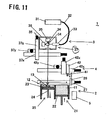
- the manufacturing equipment 1 comprises a powder layer forming portion (powder layer forming means) 2 that supplies metal powder 11 and forms a powder layer 12, a light beam irradiator (light beam irradiation means) 3 that irradiates a given point on a powder layer 12, which is formed by the powder layer forming portion 2, with light beams so as to sinter the powder layer 12 and thus form a sintered layer 13, a cutter (cutting means) 4 that cuts a three-dimensionally shaped object in which sintered layers 13 are integrally stacked, and a controller 5 that controls the operation of each portion.
- a metal powder sintered component in process is referred to as a shaped object.
- the powder layer forming portion 2 has a material tank 21 that supplies metal powder, a material table 22 that moves metal powder in the material tank 21 upward, a substrate 23 on which a powder layer 12 is placed, a formation table 24 that holds the substrate 23 and moves up and down, a formation tank 25 that surrounds the formation table 24, a wiper 26 that spreads the metal powder contained in the material tank 21 onto the substrate 23, and a wiper moving shaft 27 that moves the wiper 26.
- the light beam irradiator 3 has a light beam oscillator 31 that emits light beams, an optical fiber 32 that transmits light beams L emitted, and an optical component 33 that includes a condenser lens (not shown) and collects light beams L received from the optical fiber 32.
- the light beam oscillator 31 is an oscillator for e.g., carbon dioxide laser, YAG laser, or fiber laser.
- the light beam irradiator 3 further comprises two rotatable scan mirrors 34 that reflect light beams L from the optical component 33, and a scanner 35 that controls the rotation angles of the scan mirrors 34.
- the controller 5 adjusts the rotation angles of the scan mirrors 34 via the scanner 35 to direct light beams L over a powder layer 12 for scanning.
- the optical component 33, the scan mirrors 34, and the scanner 35 are covered by an optical cover 36 and make up a scan head 37 together with the optical cover 36.
- the scan head 37 moves in a direction parallel to the surface irradiated with light beams by a scan head X shaft 37x, which is parallel to the irradiated surface and moves in the X direction, and a scan head Y shaft 37y, which is parallel to the irradiated surface and moves in the Y direction.
- the cutter 4 comprises a cutting tool 41 that cuts a shaped object and a milling head 42 that rotates and holds the cutting tool 41.
- the milling head 42 is fixed on a milling head Z shaft 42z, and moves in a direction normal to and in a direction parallel to the surface irradiated with light beams by the milling head Z shaft 42z, a milling head X shaft 42x, and a milling head Y shaft 42y
- the milling head Z shaft 42z, the milling head X shaft 42x, and the milling head Y shaft 42y make up a milling head moving portion (milling head moving means) 43.
- the surface irradiated with light beams is covered by a chamber (not shown), which is filled with inert gas such as nitrogen gas so as to prevent oxidation of metal powder.
- the supply of inert gas is controlled by measuring the level of oxygen or the like within the chamber.
- FIGS. 4A to 4D show the operation in sequence.
- the formation table 24 is moved down so that the difference in level between the top face of the substrate 23 and the top face of the formation tank 25 reaches ⁇ t in length, and the metal powder 11 on the material table 22 is supplied onto the substrate 23 by the wiper 26 so as to form a powder layer 12 ( FIG. 4A ).
- the scan head 37 rotates the scan mirrors to direct light beams L over an area of the powder layer 12 for scanning so that the powder layer 12 is melted to form a sintered layer 13 ( FIG. 4B ).
- the scan head 37 then moves to another area of the powder layer 12 by the scan head X shaft and the scan head Y shaft, and irradiates the area with light beams L to form the sintered layer 13 ( FIG. 4C ).
- the scan head 37 repeats the operation of FIGS. 4A to 4C so as to repeatedly form powder layers 12 and sintered layers 13, so that the sintered layers 13 are stacked.
- the surface layer of a surface part and an unwanted part of the shaped object are cut by the cutting tool 41 of the milling head 42 ( FIG. 4D ). This process is repeated to manufacture a metal powder sintered component.
- the scan head 37 can be moved in a direction parallel to the irradiated surface, a large area can be scanned while a short distance is maintained between the scan head 37 and the irradiated surface.
- a large metal powder sintered component can be manufactured.
- the short distance between the scan head 37 and the irradiated surface can prevent a reduction in the accuracy of light beam L scanning, thus enhancing the dimensional accuracy of a shaped object. Since the dimensional accuracy of a shaped object is high, the amount of cutting by the cutting tool 41 can be reduced so that the cutting time can be reduced to shorten the machining time.
- a scan head 37 moves not in a direction parallel to the irradiated surface but in a direction normal thereto, unlike the first embodiment.
- Components like those in the above described embodiment are denoted by like numerals in the drawings and will not be further explained (the same shall apply hereinafter).
- the scan head 37 moves in a direction normal to the surface irradiated with light beams by a scan head 37z.
- FIGS. 8A to 8C show the operation in sequence.
- a powder layer 12 is formed on a substrate 23 ( FIG. 8A ).
- the scan head 37 rotates scan mirrors to direct light beams L over the powder layer 12 for scanning so that the powder layer 12 is melted to form a sintered layer 13 ( FIG. 8B ).
- the scan head 37 then repeats the operation of FIGS. 8A and 8B so as to repeatedly form powder layers 12 and sintered layers 13, so that the sintered layers 13 are stacked.
- the surface layer of a surface part and an unwanted part of the shaped object are cut by a cutting tool 41 of a milling head 42 ( FIG. 8C ). This process is repeated to manufacture a metal powder sintered component.
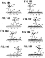
- FIGS. 9A and 9B show the relationship between the irradiation height H of the scan head 37 and the accuracy of light beam L scanning.
- FIG. 9A shows a case where the irradiation height H of the scan head 37 is large while FIG. 9B shows a case where the irradiation height H is small. If a light beam L directed from the scan head 37 is deviated by the same angle ⁇ , the larger irradiation height H results in a lower accuracy of light beam L scanning because the amplitude of the light beam L is larger.
- the accuracy of light beam L scanning can be varied. If scanning with a high degree of accuracy is needed, the irradiation height H of the scan head 37 is set small. If high scanning accuracy is not needed, the irradiation height H of the scan head 37 is set large for irradiation with light beams L.
- FIGS. 10A to 10C show the relationship between the irradiation height H of the scan head 37 and the diameter D of focused light beams L.
- FIG. 10A shows the diameter D of focused light beams in the case where the irradiation height H of the scan head 37 is larger than average
- FIG. 10B shows the diameter D of focused light beams in the case where the irradiation height H is average
- FIG. 10C shows the diameter D of focused light beams in the case where the irradiation height H is smaller than average.
- the diameter D of focused light beams is larger than that in the case where the irradiation height H is average.
- the diameter D of focused light beams is smaller than that in the case where the irradiation height H is average.
- the diameter D of focused light beams can be easily controlled by changing the irradiation height H while maintaining the condenser lens and the like in the same condition. In this manner, the accuracy of light beam L scanning and the diameter of focused light beams can be easily controlled by varying the irradiation height H according to the needs of a shaped object. Thus, the machining time can be reduced.
- a scan head 37 moves in a direction parallel to and in a direction normal to the irradiated surface.
- a scan head Z shaft 37z is connected to a scan head Y shaft 37y, and the scan head 37 is held on the scan head Z shaft 37z.
- a scan head 37 according to this embodiment is fixed on a milling head 42.
- the scan head 37 moves in a direction parallel to and in a direction normal to the surface irradiated with light beams by a milling head X shaft 42x, a milling head Y shaft 42y, and a milling head Z shaft 42z.
- the scan head 37 is fixed on the milling head 42 for movement. This can eliminate the need for a scan head X shaft, a scan head Y shaft, and a scan head Z shaft to move the scan head 37, thus simplifying the configuration of the manufacturing equipment and reducing the cost. Further, since the scan head 37 is not needed during the process of cutting a surface part or the like of a shaped object, it can be detached from the milling head 42 before the start of the cutting process and can be attached to the milling head 42 before irradiation with light beams L after the completion of the cutting process. If the scan head 37 is detached during the cutting process in this manner, the scan head 37 is less likely to be damaged by a rapidly accelerated motion of the milling head 42 during the cutting process.
- FIGS. 13A and 13B show the conditions of irradiation with light beams from a scan head 37, wherein FIG. 13A shows a condition with the largest irradiation height H, and FIG. 13B shows a condition with the smallest irradiation height H.
- Manufacturing equipment according to this embodiment is similar in configuration to the third embodiment.
- a controller in the manufacturing equipment needs to adjust the light beam L irradiation position and the diameter D of focused light beams to set values according to the irradiation height H of the scan head 37.
- the adjustment of the irradiation position is made by the rotation angles of scan mirrors 34, and the adjustment of the diameter D of focused light beams is made by the position of a condenser lens in an optical component 33 and so on.
- adjustment data ( ⁇ X, ⁇ Y) on the irradiation position and adjustment data ( ⁇ Z) on the diameter of focused light beams at the position with the largest irradiation height H and the position with the smallest irradiation height H are determined.
- the adjustment data at the position with the largest irradiation height H is set as a first adjustment data
- the adjustment data at the position with the smallest irradiation height H is set as a second adjustment data.
- the adjustments are made with the same irradiated area R and diameter of focused light beams.
- adjustment data for an arbitrary height H of the scan head 37 is determined by interpolation from the first adjustment data and the second adjustment data, according to the height.
- adjustment data ⁇ X for the case where the irradiation height is just intermediate between the highest and the lowest is 0.15 mm.
- adjustment data to adjust, to set values, the light beam L irradiation position and the diameter of focused light beams for an arbitrary irradiation height H of the scan head 37 can be easily determined, which can enhance the accuracy of light beam L scanning.
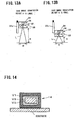
- FIG. 14 shows a vertical section of a shaped object.
- Manufacturing equipment according to this embodiment is similar in configuration to the third embodiment.
- irradiation with light beams is performed as described below.
- a shaped object 14 is sectionalized into configuration areas of a surface portion V1, a center portion V3, and an intermediate portion V2 between the surface portion and the center portion.
- the sintered density is varied depending on the configuration areas so that the density in the surface portion V1 is 98% or more, the density in the intermediate portion V2 is 70-90%, and the density in the center portion V3 is 60-80%.
- the sintered density can be varied by the diameter of focused light beams.
- the irradiation height for the surface portion V1 is set small because the portion should be scanned with a high degree of accuracy in order to reduce the amount of surface cutting after the formation.
- the irradiation energy per unit area is increased to increase the sintered density
- the irradiation height is set large because the dimensional accuracy of the shaped object is not affected even if the irradiation position deviates and thus the scan accuracy can be low.
- the irradiation energy per unit area is decreased to decrease the sintered density Further, since the irradiation height is large, the light beam scanning speed is high so as to decrease the sintered density even if the angular velocity of rotation of the scan mirrors is the same as that in the case where the irradiation height is small.
- the intermediate portion V2 is irradiated with an irradiation height between the irradiation height for the irradiation of the surface portion V1 and the irradiation height for the irradiation of the center portion V3.
- the sintered density may also be varied by the laser output, the scanning speed, or the scanning pitch.
- the accuracy of light beam scanning is high because the irradiation is performed with the small irradiation height. Since scanning with a high degree of accuracy reduces the surface cutting amount, the cutting time can be reduced to shorten the machining time. Further, for the center portion of a shaped object, the scan accuracy and the sintered density can be low. Therefore, the irradiation height can be set large to increase the scanning speed so that the machining time can be shortened.
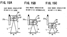
- FIGS. 15A to 15C show the conditions of irradiation with light beams from a scan head 37.
- Manufacturing equipment according to this embodiment is similar in configuration to the third embodiment.
- a number of irradiation heights are set in advance, and the scan head performs irradiation with light beams based on adjustment data according to the respective irradiation heights.
- FIG. 15 shows a case where three levels are set as irradiation heights, wherein FIG. 15A shows the condition of irradiation in the case where the irradiation height H is large, FIG.
- FIG. 15B shows the condition of irradiation in the case where the irradiation height H is intermediate
- FIG. 15C shows the condition of irradiation in the case where the irradiation height H is small.
- irradiation with light beams is performed at a high position in the case where irradiation at high speed is needed, at a low position in the case where irradiation with a high degree of accuracy is needed, and at an intermediate position in the case where irradiation in average condition is needed.
- the condition of irradiation with light beams can be easily changed according to the need for the accuracy and speed of scanning of a shaped object.
- the machining time can be shortened.
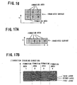
- FIG. 16 shows an irradiated surface.
- the irradiated surface is divided into a number of formation areas.
- the numerals shown in the formation areas are formation area numbers for description (the same shall apply hereinafter).
- the irradiated surface is divided into the number of formation areas, within which a scan head is moved to formation areas not adjacent to each other in turn by a scan head X shaft and a scan head Y shaft, and the scan mirrors are rotated to direct light beams over the formation areas for scanning.
- a scan head X shaft and a scan head Y shaft the scan mirrors are rotated to direct light beams over the formation areas for scanning.
- irradiation with light beams is repeated for the formation areas in the order of, for example, the numbers “1”, “5", “3”, “4", “2”, and “6". Since formation areas not adjacent to each other are irradiated with light beams in turn, sintering heat is prevented from accumulating in the shaped object so as to prevent heat strain of the shaped object and thus enhance the dimensional accuracy of the shaped object.
- FIG. 17A shows an irradiated surface
- FIG. 17B shows a vertical section of the shaped object.
- the irradiated surface is divided into a number of formation areas, within which a scan head is moved in turn to scan the formation areas with light beams. This division is made so that a boundary between formation areas of a sintered layer formed under the irradiated surface does not overlap a boundary between formation areas of the irradiated surface to be irradiated with light beams.
- irradiation with light beams is repeated in the order of the formation area numbers "1", “3", “2", and "4".
- the boundaries between the formation areas are different in position between sintered layers stacked one on top of the other, so that the boundaries do not overlap between sintered layers vertically adjacent to each other.
- FIG. 18 shows irradiation with light beams in sequence.
- a scan head 37 is first positioned above the formation area "1”, and irradiates the formation area “1” with light beams ( FIG. 18A ). Then, the scan head 37 moves to above the formation area "3", and irradiates the formation area "3” with light beams ( FIG. 18B ). Subsequently, the scan head 37 irradiates the formation areas "2" and "4" with light beams in like manner to sinter the first layer ( FIGS. 18C and 18D ).
- the formation area "1" in the second layer is irradiated with light beams so that the boundary between the formation area “1” and the formation area “2" is not aligned with the boundary in the first layer ( FIG. 18E ).
- the scan head 37 moves to above the formation area “3” and irradiates the formation area "3” with light beams so that the boundary is not aligned with that in the first layer ( FIG. 18F ).
- the formation areas "2" and "4" are irradiated with light beams in like manner to sinter the second layer ( FIGS. 18G and 18H ).
- FIG. 19A shows a shaped object 14 formed in the above manner
- FIG. 19B shows a shaped object 14 with the boundaries between formation areas in sintered layers aligned.
- FIG. 20A shows a horizontal section of a shaped object
- FIG. 20B shows a vertical section of the shaped object
- FIG. 20C shows part of formation area in the shaped object that is separated.
- the irradiated surface is sectionalized into configuration areas corresponding to a center portion, a surface portion, and an intermediate portion between the center portion and the surface portion, respectively, in the shaped object to be formed at the irradiated surface.
- Each of the configuration areas sectionalized is further divided into a number of formation areas.
- a scan head is moved to formation areas not adjacent to each other in turn within the divided formation areas, and the scan mirrors are rotated to direct light beams over the formation areas for scanning. Since formation areas not adjacent to each other are irradiated with light beams in turn, sintering heat is prevented from accumulating in the shaped object so as to prevent heat strain of the shaped object and thus enhance the dimensional accuracy of the shaped object.
- irradiation with light beams is repeated in the order of, for example, the formation areas "1", “6", “9", “2”, “8", “10”, “4", “7”, “12”, “3”, “5", and “11".
- the sintered density is varied depending on the configuration areas so that the density in the surface portion is 98% or more, the density in the intermediate portion is 70-90%, and the density in the center portion is 60-80%.
- a small irradiation height is set for the surface portion
- a large irradiation height is set for the center portion
- an intermediate irradiation height is set for the intermediate portion, like the above described sixth embodiment.
- the scan accuracy is high to decrease the diameter of focused light beams and thus increase the sintered density
- the irradiation height is large, the scanning speed is increased while the sintered density is decreased. Accordingly, since heat strain of a shaped object can be prevented and the accuracy of light beam scanning for a surface portion of the shaped object can be increased, a large object can be formed with a high degree of accuracy
- the formation may be made so that a boundary between formation areas in a sintered layer already formed under the irradiated surface does not vertically overlap a boundary between formation areas in the irradiated surface to be irradiated with light beams, like the first modified example.
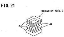
- FIG. 21 shows the shape of the formation area "3" of the center portion in FIG. 20C that is formed so that boundaries between formation areas in the irradiated surface do not overlap vertically.
- the formation area "3" has a portion A entering into an adjacent formation area and a portion B into which an adjacent formation area enters.
- the positions of the boundaries between the formation area "3" and other formation areas are different between sintered layers, so that the boundaries in sintered layers vertically adjacent to each other do not overlap but the formation areas are incorporated into each other. This can increase the strength between the formation areas, thus making the shaped object firm.
- the present invention is not limited to the configurations of the above described embodiments, and various kinds of modification can be done in a scope without changing the purpose of the invention.
- the inside of a chamber covering an irradiated surface may be under vacuum atmosphere. In this case, effects similar to those in the case where the chamber is filled with inert gas can be also achieved.
Landscapes
- Chemical & Material Sciences (AREA)
- Engineering & Computer Science (AREA)
- Manufacturing & Machinery (AREA)
- Materials Engineering (AREA)
- Powder Metallurgy (AREA)
Description
- The present invention relates to manufacturing equipment and manufacturing methods for forming a metal powder sintered component by irradiating metal powder with light beams.
- Equipment for manufacturing a metal powder sintered component by irradiating a powder layer, which is made of metal powder, with light beams to melt the powder layer for formation of a sintered layer and repeating the process of forming another powder layer on the sintered layer and irradiating it with light beams (hereinafter, referred to as manufacturing equipment) is known in the prior art.
FIG. 22 shows a configuration of the manufacturing equipment. Themanufacturing equipment 101 comprises amaterial tank 121 that suppliesmetal powder 111, asubstrate 123 on which apowder layer 112 is placed, a formation table 124 that holds thesubstrate 123 and moves up and down, awiper 126 that spreads themetal powder 111 contained in thematerial tank 121 onto thesubstrate 123, alight beam oscillator 131 that emits light beams L, ascan head 137 that directs light beams L emitted from thelight beam oscillator 131 onto thepowder layer 112 for scanning, and acontroller 105 that controls the operation of themanufacturing equipment 101. - The
scan head 137 comprises acondenser lens 138 that collects light beams L, tworotatable scan mirrors 134 that reflect light beams L, and ascanner 135 that controls the rotation angles of thescan mirrors 134. Thecontroller 105 causes thelight beam oscillator 131 to emit light beams L and collects the emitted light beams L by thecondenser lens 138. Then, thecontroller 105 causes thescanner 135 to rotate thescan mirrors 134 so that thescan mirrors 134 reflect the collected light beams L onto thepowder layer 112 to sinter themetal powder 111 and thus form a sinteredlayer 113. - However, in the manufacturing equipment, if the rotation angles of the
scan mirrors 134 are increased to enlarge the irradiated area, focusing and so on become difficult and thus the accuracy of light beam L scanning is reduced. Further, since the irradiation height is fixed, the accuracy of light beam L scanning cannot be adjusted.FIG. 23 shows the relationship between the irradiation height and the irradiated area. When the irradiation height is changed from a height H1 to a height H2, the irradiated area increases from an irradiated area R1 to an irradiated area R2. However, the accuracy of light beam L scanning is reduced because the irradiation position is changed significantly by slight rotation of thescan mirrors 134. - Plotter type manufacturing equipment is also known.
FIG. 24 shows a configuration of the manufacturing equipment. Themanufacturing equipment 201 comprises alight beam oscillator 231 that emits light beams L, two mirrors, anX-reflection mirror 232 and a Y-reflection mirror 233, that reflect light beams L, anoptical component 234 that focuses reflected light beams L, aformation tank 225 where apowder layer 212 is placed, anX-movement shaft 235 that moves theX-refection mirror 232 in the X direction, and a Y-movement shaft 236 that moves the Y-reflection mirror 233 in the Y direction. Light beams L emitted from thelight beam oscillator 231 are reflected by theX-reflection mirror 232 and the Y-reflection mirror 233, focused on thepowder layer 212 by theoptical component 234, and directed over thepowder layer 212 for scanning by theX-movement shaft 235 and the Y-movement shaft 236. - However, in the
manufacturing equipment 201, the accuracy of light beam L scanning is low.FIG. 25 shows the relationship between the irradiation angle of light beams L from thelight beam oscillator 231 and the error in irradiation position. Since light beams L are large in optical axis length, even a slight deviation of the irradiation angle of light beams L from thelight beam oscillator 231 causes a large error in irradiation position.FIG. 26 shows the relationship between the deviation of the optical axis of a light beam L from the moving direction of theX-reflection mirror 232 and the error in irradiation position. A slight deviation of the optical axis of the light beam L from the moving direction of theX-reflection mirror 232 causes a larger error in irradiation position as the travel distance becomes longer. A deviation of the optical axis of the light beam L from the moving direction of the Y-reflection mirror 233 also causes a large error in irradiation position. - Manufacturing equipment is also known in which a light beam oscillator and a scan head for directing light beams move in a single direction parallel to a powder layer for light beam scanning (see, for example,
JP 2004-122489 A - However, in the manufacturing equipment as disclosed in
JP 2004-122489 A EP 1 661 657 A1 discloses a laser processing robot system including a manipulator, a laser processing tool attached to the manipulator, and a control unit for controlling operations of the manipulator and the laser processing tool. The laser processing tool includes a laser scan head with a movable mirror incorporated therein, and a movable support mechanism movably supporting the laser scan head. The control unit includes a rapid-traverse operation controlling section for controlling an operation of the movable support mechanism to make the laser scan head perform a rapid-traverse operation during a non-processing period when the laser scan head does not emit a laser beam.US 2004/0094728 A1 describes a device for sintering, removing material and/or labeling by means of electromagnetically bundled radiation, especially a laser sintering machine and/or a laser surface-processing machine. The device comprises a construction space which is accommodated in a machine housing and in which the following are provided: a scanner, into which the beam of a sintering laser is coupled; a vertically displaceable workpiece platform; and a material supply device comprising a coater for supplying sintering material in powder, paste or liquid form to the process area above the workpiece platform, from a supply container.EP 1 583 628 A1 - The present invention has been made to solve the above described problems. An object of the present invention is to provide manufacturing equipment and manufacturing methods for a metal powder sintered component that can provide a large irradiated area and a high accuracy in light beam scanning as well as allowing the accuracy of light beam scanning to be adjusted as the need arises.
- In order to achieve the above mentioned object, the present invention provides a method of manufacturing a metal powder sintered component according to
claim 1. - According to the present invention, the irradiated area can be increased because the scan head moves parallel to the irradiated surface, and, by setting the irradiation height small, the accuracy of light beam scanning can be enhanced. Further, the scan head can move in the direction normal to the irradiated surface so as to change the irradiation height. Therefore, by changing the irradiation height of the scan head, the accuracy of light beam scanning can be adjusted.
- It is preferable that the manufacturing equipment comprises cutting means that repeatedly cuts a surface layer of a surface part and an unwanted part of the shaped object at least one time in process of the formation of the shaped object, the cutting means has a milling head that moves in a direction parallel to and in a direction normal to the irradiated surface, and the scan head moves by milling head moving means that moves the milling head. Thereby, since the scan head is fixed on the milling head for movement, the configuration of the manufacturing equipment for a metal powder sintered component can be simplified and the cost can be reduced.
- The controller has: first adjustment data to adjust, to set values, a light beam irradiation position and a diameter of focused light beams in a case where the scan head is positioned at an irradiation height closest to the irradiated surface; and second adjustment data to adjust, to set values, a light beam irradiation position and a diameter of focused light beams in a case where the scan head is positioned at an irradiation height farthest from the irradiated surface, and adjustment data for a case where the scan head is positioned at an arbitrary irradiation height is determined by interpolation from the first adjustment data and the second adjustment data, so that irradiation with light beams is performed using the determined adjustment data. This can make it easy to determine adjustment data to adjust, to set values, the light beam irradiation position and the diameter of focused light beams for an arbitrary irradiation height of the scan head, thus enhancing the accuracy of light beam scanning.
- It is preferable that the scan head irradiates a surface portion of a shaped object with light beams from a position close to the irradiated surface, and irradiates a center portion of a shaped object with light beams from a position far from the irradiated surface. Thereby, since the surface portion of a shaped object is irradiated with light beams from a position close to the irradiated surface, the accuracy of light beam scanning can be enhanced. This can reduce the cutting amount of the surface of a shaped object, thus decreasing the cutting time to shorten the machining time. Further, for the center portion of a shaped object, the scan accuracy and the sintered density can be low. Therefore, the portion can be irradiated from a position far from the irradiated surface so as to increase the scanning speed and thus shorten the machining time.
- It is preferable that the controller causes the scan head to perform irradiation with light beams from a number of irradiation heights set in advance based on adjustment data according to the respective irradiation heights to adjust light beam irradiation positions and diameters of focused light beams to set values. Thereby, since irradiation with light beams is performed from a number of irradiation heights set in advance, the condition of irradiation with light beams can be easily changed according to the need for the accuracy and speed of scanning of a shaped object, so that the machining time can be shortened.
- The irradiated surface is divided into a number of formation areas, and the scan head is moved to formation areas not adjacent to each other in turn within the divided formation areas, for irradiation with light beams. Thereby, since formation areas not adjacent to each other are irradiated with light beams in turn, sintering heat is prevented from accumulating in the shaped object so as to prevent heat strain of the shaped object and thus enhance the processing accuracy of the shaped object.
- The irradiated surface is divided into a number of formation areas, and the scan head is moved in turn in the divided formation areas for irradiation with light beams, and the division is made so that a boundary between formation areas of a sintered layer formed under an irradiated surface does not overlap a boundary between formation areas of the irradiated surface. Thereby, since the irradiated surface is divided so that a boundary between formation areas of a sintered layer formed under the irradiated surface does not overlap a boundary between formation areas of the irradiated surface, the strength between the formation areas in the shaped object can be increased.
- It is preferable that the irradiated surface is sectionalized into configuration areas corresponding to a center portion, a surface portion, and an intermediate portion between the center portion and the surface portion, respectively, of a shaped object to be formed, each of the configuration areas sectionalized is further divided into a number of formation areas, and the scan head is moved to formation areas not adjacent to each other in turn within the divided formation areas, for irradiation with light beams. Thereby, since the irradiated surface is divided into a number of formation areas and the irradiation height can be set according to the formation areas, the scan accuracy for the surface portion of a shaped object can be increased by setting the irradiation height small. Further, since formation areas not adjacent to each other are irradiated with light beams in turn, sintering heat is prevented from accumulating in the shaped object so as to prevent heat strain of the shaped object. Accordingly, a large object can be formed with a high degree of accuracy.
- It is preferable that the irradiated surface is sectionalized into configuration areas corresponding to a center portion, a surface portion, and an intermediate portion between the center portion and the surface portion, respectively, of a shaped object to be formed, each of the configuration areas sectionalized is further divided into a number of formation areas, and the scan head is moved to formation areas not adjacent to each other in turn within the divided formation areas, for irradiation with light beams, and the division is made so that a boundary between formation areas of a sintered layer formed under the irradiated surface does not overlap a boundary between formation areas of the irradiated surface. This can increase the strength between the formation areas, thus making the shaped object firm.
- Referring to
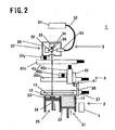
FIG. 1 to FIG. 4 , manufacturing equipment for a metal powder sintered component (hereinafter, referred to as manufacturing equipment) according to a first embodiment of the present invention is described. InFIG. 1 to FIG. 3 , themanufacturing equipment 1 comprises a powder layer forming portion (powder layer forming means) 2 that suppliesmetal powder 11 and forms apowder layer 12, a light beam irradiator (light beam irradiation means) 3 that irradiates a given point on apowder layer 12, which is formed by the powderlayer forming portion 2, with light beams so as to sinter thepowder layer 12 and thus form a sinteredlayer 13, a cutter (cutting means) 4 that cuts a three-dimensionally shaped object in which sinteredlayers 13 are integrally stacked, and acontroller 5 that controls the operation of each portion. In this specification, a metal powder sintered component in process is referred to as a shaped object. - The powder
layer forming portion 2 has amaterial tank 21 that supplies metal powder, a material table 22 that moves metal powder in thematerial tank 21 upward, asubstrate 23 on which apowder layer 12 is placed, a formation table 24 that holds thesubstrate 23 and moves up and down, aformation tank 25 that surrounds the formation table 24, awiper 26 that spreads the metal powder contained in thematerial tank 21 onto thesubstrate 23, and awiper moving shaft 27 that moves thewiper 26. Thelight beam irradiator 3 has alight beam oscillator 31 that emits light beams, anoptical fiber 32 that transmits light beams L emitted, and anoptical component 33 that includes a condenser lens (not shown) and collects light beams L received from theoptical fiber 32. Thelight beam oscillator 31 is an oscillator for e.g., carbon dioxide laser, YAG laser, or fiber laser. Thelight beam irradiator 3 further comprises two rotatable scan mirrors 34 that reflect light beams L from theoptical component 33, and ascanner 35 that controls the rotation angles of the scan mirrors 34. Thecontroller 5 adjusts the rotation angles of the scan mirrors 34 via thescanner 35 to direct light beams L over apowder layer 12 for scanning. Theoptical component 33, the scan mirrors 34, and thescanner 35 are covered by anoptical cover 36 and make up ascan head 37 together with theoptical cover 36. - The
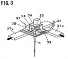
scan head 37 moves in a direction parallel to the surface irradiated with light beams by a scanhead X shaft 37x, which is parallel to the irradiated surface and moves in the X direction, and a scanhead Y shaft 37y, which is parallel to the irradiated surface and moves in the Y direction. Thecutter 4 comprises acutting tool 41 that cuts a shaped object and a millinghead 42 that rotates and holds thecutting tool 41. The millinghead 42 is fixed on a millinghead Z shaft 42z, and moves in a direction normal to and in a direction parallel to the surface irradiated with light beams by the millinghead Z shaft 42z, a millinghead X shaft 42x, and a millinghead Y shaft 42y The millinghead Z shaft 42z, the millinghead X shaft 42x, and the millinghead Y shaft 42y make up a milling head moving portion (milling head moving means) 43. The surface irradiated with light beams is covered by a chamber (not shown), which is filled with inert gas such as nitrogen gas so as to prevent oxidation of metal powder. The supply of inert gas is controlled by measuring the level of oxygen or the like within the chamber. - The operation of the
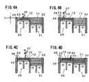
manufacturing equipment 1 configured as described above is described.FIGS. 4A to 4D show the operation in sequence. First, the formation table 24 is moved down so that the difference in level between the top face of thesubstrate 23 and the top face of theformation tank 25 reaches Δt in length, and themetal powder 11 on the material table 22 is supplied onto thesubstrate 23 by thewiper 26 so as to form a powder layer 12 (FIG. 4A ). - Subsequently, the
scan head 37 rotates the scan mirrors to direct light beams L over an area of thepowder layer 12 for scanning so that thepowder layer 12 is melted to form a sintered layer 13 (FIG. 4B ). Thescan head 37 then moves to another area of thepowder layer 12 by the scan head X shaft and the scan head Y shaft, and irradiates the area with light beams L to form the sintered layer 13 (FIG. 4C ). Subsequently, thescan head 37 repeats the operation ofFIGS. 4A to 4C so as to repeatedly form powder layers 12 and sinteredlayers 13, so that thesintered layers 13 are stacked. When sintered layers 13 reach a given thickness, the surface layer of a surface part and an unwanted part of the shaped object are cut by the cuttingtool 41 of the milling head 42 (FIG. 4D ). This process is repeated to manufacture a metal powder sintered component. - According to the
manufacturing equipment 1, since thescan head 37 can be moved in a direction parallel to the irradiated surface, a large area can be scanned while a short distance is maintained between thescan head 37 and the irradiated surface. Thus, a large metal powder sintered component can be manufactured. The short distance between thescan head 37 and the irradiated surface can prevent a reduction in the accuracy of light beam L scanning, thus enhancing the dimensional accuracy of a shaped object. Since the dimensional accuracy of a shaped object is high, the amount of cutting by the cuttingtool 41 can be reduced so that the cutting time can be reduced to shorten the machining time. - Referring to
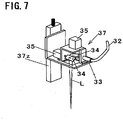
FIG. 5 to FIG. 10 , a second embodiment of the present invention is described. Inmanufacturing equipment 1 according to this embodiment, ascan head 37 moves not in a direction parallel to the irradiated surface but in a direction normal thereto, unlike the first embodiment. Components like those in the above described embodiment are denoted by like numerals in the drawings and will not be further explained (the same shall apply hereinafter). InFIG. 5 to FIG. 7 , thescan head 37 moves in a direction normal to the surface irradiated with light beams by ascan head 37z. - The operation of the
manufacturing equipment 1 configured as described above is described.FIGS. 8A to 8C show the operation in sequence. First, likeFIG. 4A in the first embodiment, apowder layer 12 is formed on a substrate 23 (FIG. 8A ). - Subsequently, the
scan head 37 rotates scan mirrors to direct light beams L over thepowder layer 12 for scanning so that thepowder layer 12 is melted to form a sintered layer 13 (FIG. 8B ). Thescan head 37 then repeats the operation ofFIGS. 8A and 8B so as to repeatedly form powder layers 12 and sinteredlayers 13, so that thesintered layers 13 are stacked. When sintered layers 13 reach a given thickness, the surface layer of a surface part and an unwanted part of the shaped object are cut by acutting tool 41 of a milling head 42 (FIG. 8C ). This process is repeated to manufacture a metal powder sintered component. -
FIGS. 9A and 9B show the relationship between the irradiation height H of thescan head 37 and the accuracy of light beam L scanning.FIG. 9A shows a case where the irradiation height H of thescan head 37 is large whileFIG. 9B shows a case where the irradiation height H is small. If a light beam L directed from thescan head 37 is deviated by the same angle θ, the larger irradiation height H results in a lower accuracy of light beam L scanning because the amplitude of the light beam L is larger. - By varying the irradiation height of the
scan head 37 in this manner, the accuracy of light beam L scanning can be varied. If scanning with a high degree of accuracy is needed, the irradiation height H of thescan head 37 is set small. If high scanning accuracy is not needed, the irradiation height H of thescan head 37 is set large for irradiation with light beams L. -
FIGS. 10A to 10C show the relationship between the irradiation height H of thescan head 37 and the diameter D of focused light beams L.FIG. 10A shows the diameter D of focused light beams in the case where the irradiation height H of thescan head 37 is larger than average,FIG. 10B shows the diameter D of focused light beams in the case where the irradiation height H is average, andFIG. 10C shows the diameter D of focused light beams in the case where the irradiation height H is smaller than average. When the irradiation height H is larger than average, the diameter D of focused light beams is larger than that in the case where the irradiation height H is average. When the irradiation height H is smaller than average, the diameter D of focused light beams is smaller than that in the case where the irradiation height H is average. The diameter D of focused light beams can be easily controlled by changing the irradiation height H while maintaining the condenser lens and the like in the same condition. In this manner, the accuracy of light beam L scanning and the diameter of focused light beams can be easily controlled by varying the irradiation height H according to the needs of a shaped object. Thus, the machining time can be reduced. - Referring to
FIG. 11 , a third embodiment of the present invention is described. Inmanufacturing equipment 1 according to this embodiment shown inFIG. 11 , ascan head 37 moves in a direction parallel to and in a direction normal to the irradiated surface. A scanhead Z shaft 37z is connected to a scanhead Y shaft 37y, and thescan head 37 is held on the scanhead Z shaft 37z. With this configuration, since thescan head 37 can move not only in a direction parallel to the irradiated surface but also in a direction normal to the irradiated surface, effects similar to those of the above described first and second embodiments can be achieved. - Referring to
FIG. 12 , a fourth embodiment of the present invention is described. InFIG. 12 , ascan head 37 according to this embodiment is fixed on a millinghead 42. Thescan head 37 moves in a direction parallel to and in a direction normal to the surface irradiated with light beams by a millinghead X shaft 42x, a millinghead Y shaft 42y, and a millinghead Z shaft 42z. - As described above, the
scan head 37 is fixed on the millinghead 42 for movement. This can eliminate the need for a scan head X shaft, a scan head Y shaft, and a scan head Z shaft to move thescan head 37, thus simplifying the configuration of the manufacturing equipment and reducing the cost. Further, since thescan head 37 is not needed during the process of cutting a surface part or the like of a shaped object, it can be detached from the millinghead 42 before the start of the cutting process and can be attached to the millinghead 42 before irradiation with light beams L after the completion of the cutting process. If thescan head 37 is detached during the cutting process in this manner, thescan head 37 is less likely to be damaged by a rapidly accelerated motion of the millinghead 42 during the cutting process. - Referring to
FIG. 13 , the present invention is described.FIGS. 13A and 13B show the conditions of irradiation with light beams from ascan head 37, whereinFIG. 13A shows a condition with the largest irradiation height H, andFIG. 13B shows a condition with the smallest irradiation height H. Manufacturing equipment according to this embodiment is similar in configuration to the third embodiment. When the irradiation height H of thescan head 37 is changed for irradiation with light beams L, a controller in the manufacturing equipment needs to adjust the light beam L irradiation position and the diameter D of focused light beams to set values according to the irradiation height H of thescan head 37. The adjustment of the irradiation position is made by the rotation angles of scan mirrors 34, and the adjustment of the diameter D of focused light beams is made by the position of a condenser lens in anoptical component 33 and so on. - In the invention, adjustment data (ΔX, ΔY) on the irradiation position and adjustment data (ΔZ) on the diameter of focused light beams at the position with the largest irradiation height H and the position with the smallest irradiation height H are determined. The adjustment data at the position with the largest irradiation height H is set as a first adjustment data, and the adjustment data at the position with the smallest irradiation height H is set as a second adjustment data. The adjustments are made with the same irradiated area R and diameter of focused light beams. Then, adjustment data for an arbitrary height H of the
scan head 37 is determined by interpolation from the first adjustment data and the second adjustment data, according to the height. For example, when ΔX of the first adjustment data is 0.1 mm and ΔX of the second adjustment data is 0.2 mm, adjustment data ΔX for the case where the irradiation height is just intermediate between the highest and the lowest is 0.15 mm. In this manner, adjustment data to adjust, to set values, the light beam L irradiation position and the diameter of focused light beams for an arbitrary irradiation height H of thescan head 37 can be easily determined, which can enhance the accuracy of light beam L scanning. - Referring to
FIG. 14 , a sixth embodiment of the present invention is described.FIG. 14 shows a vertical section of a shaped object. Manufacturing equipment according to this embodiment is similar in configuration to the third embodiment. In this embodiment, irradiation with light beams is performed as described below. A shapedobject 14 is sectionalized into configuration areas of a surface portion V1, a center portion V3, and an intermediate portion V2 between the surface portion and the center portion. Then, the sintered density is varied depending on the configuration areas so that the density in the surface portion V1 is 98% or more, the density in the intermediate portion V2 is 70-90%, and the density in the center portion V3 is 60-80%. The sintered density can be varied by the diameter of focused light beams. - The irradiation height for the surface portion V1 is set small because the portion should be scanned with a high degree of accuracy in order to reduce the amount of surface cutting after the formation. By setting the irradiation height small to reduce the diameter of focused light beams, the irradiation energy per unit area is increased to increase the sintered density For the center portion V3, the irradiation height is set large because the dimensional accuracy of the shaped object is not affected even if the irradiation position deviates and thus the scan accuracy can be low. By setting the irradiation height large to increase the diameter of focused light beams, the irradiation energy per unit area is decreased to decrease the sintered density Further, since the irradiation height is large, the light beam scanning speed is high so as to decrease the sintered density even if the angular velocity of rotation of the scan mirrors is the same as that in the case where the irradiation height is small. The intermediate portion V2 is irradiated with an irradiation height between the irradiation height for the irradiation of the surface portion V1 and the irradiation height for the irradiation of the center portion V3. The sintered density may also be varied by the laser output, the scanning speed, or the scanning pitch.
- As described above, for the surface portion of a shaped object, the accuracy of light beam scanning is high because the irradiation is performed with the small irradiation height. Since scanning with a high degree of accuracy reduces the surface cutting amount, the cutting time can be reduced to shorten the machining time. Further, for the center portion of a shaped object, the scan accuracy and the sintered density can be low. Therefore, the irradiation height can be set large to increase the scanning speed so that the machining time can be shortened.
- Referring to
FIG. 15 , a seventh embodiment of the present invention is described.FIGS. 15A to 15C show the conditions of irradiation with light beams from ascan head 37. Manufacturing equipment according to this embodiment is similar in configuration to the third embodiment. In this embodiment, a number of irradiation heights are set in advance, and the scan head performs irradiation with light beams based on adjustment data according to the respective irradiation heights.FIG. 15 shows a case where three levels are set as irradiation heights, whereinFIG. 15A shows the condition of irradiation in the case where the irradiation height H is large,FIG. 15B shows the condition of irradiation in the case where the irradiation height H is intermediate, andFIG. 15C shows the condition of irradiation in the case where the irradiation height H is small. For each of the irradiation heights, adjustment data (ΔX, ΔY) on the irradiation position and adjustment data (ΔZ) on the diameter of focused light beams are determined. The adjustments are performed with the same irradiated area R and diameter of focused light beams. Then, irradiation with light beams is performed at a high position in the case where irradiation at high speed is needed, at a low position in the case where irradiation with a high degree of accuracy is needed, and at an intermediate position in the case where irradiation in average condition is needed. - As described above, since irradiation with light beams is performed from a number of irradiation heights set in advance, the condition of irradiation with light beams can be easily changed according to the need for the accuracy and speed of scanning of a shaped object. Thus, the machining time can be shortened.
- Referring to
FIG. 16 , an eighth embodiment of the present invention is described.FIG. 16 shows an irradiated surface. The irradiated surface is divided into a number of formation areas. The numerals shown in the formation areas are formation area numbers for description (the same shall apply hereinafter). In this embodiment, the irradiated surface is divided into the number of formation areas, within which a scan head is moved to formation areas not adjacent to each other in turn by a scan head X shaft and a scan head Y shaft, and the scan mirrors are rotated to direct light beams over the formation areas for scanning. In the irradiated surface ofFIG. 16 , irradiation with light beams is repeated for the formation areas in the order of, for example, the numbers "1", "5", "3", "4", "2", and "6". Since formation areas not adjacent to each other are irradiated with light beams in turn, sintering heat is prevented from accumulating in the shaped object so as to prevent heat strain of the shaped object and thus enhance the dimensional accuracy of the shaped object. - Referring to
FIG. 17 to FIG. 19 , a first modified example of the eighth embodiment is described.FIG. 17A shows an irradiated surface andFIG. 17B shows a vertical section of the shaped object. In this modified example, the irradiated surface is divided into a number of formation areas, within which a scan head is moved in turn to scan the formation areas with light beams. This division is made so that a boundary between formation areas of a sintered layer formed under the irradiated surface does not overlap a boundary between formation areas of the irradiated surface to be irradiated with light beams. InFIGS. 17A and 17B , irradiation with light beams is repeated in the order of the formation area numbers "1", "3", "2", and "4". As shown inFIG. 17B , the boundaries between the formation areas are different in position between sintered layers stacked one on top of the other, so that the boundaries do not overlap between sintered layers vertically adjacent to each other. -
FIG. 18 shows irradiation with light beams in sequence. Ascan head 37 is first positioned above the formation area "1", and irradiates the formation area "1" with light beams (FIG. 18A ). Then, thescan head 37 moves to above the formation area "3", and irradiates the formation area "3" with light beams (FIG. 18B ). Subsequently, thescan head 37 irradiates the formation areas "2" and "4" with light beams in like manner to sinter the first layer (FIGS. 18C and 18D ). Subsequently, the formation area "1" in the second layer is irradiated with light beams so that the boundary between the formation area "1" and the formation area "2" is not aligned with the boundary in the first layer (FIG. 18E ). Then, thescan head 37 moves to above the formation area "3" and irradiates the formation area "3" with light beams so that the boundary is not aligned with that in the first layer (FIG. 18F ). Subsequently, the formation areas "2" and "4" are irradiated with light beams in like manner to sinter the second layer (FIGS. 18G and 18H ). -
FIG. 19A shows a shapedobject 14 formed in the above manner, andFIG. 19B shows a shapedobject 14 with the boundaries between formation areas in sintered layers aligned. As described above, since the irradiated surface is divided so that a boundary between formation areas of a sintered layer formed under the irradiated surface does not overlap a boundary between formation areas of the irradiated surface, the strength between the formation areas in the shaped object can be increased. - Referring to
FIGS. 20 and21 , a second modified example of the eighth embodiment is described.FIG. 20A shows a horizontal section of a shaped object,FIG. 20B shows a vertical section of the shaped object, andFIG. 20C shows part of formation area in the shaped object that is separated. In this modified example, the irradiated surface is sectionalized into configuration areas corresponding to a center portion, a surface portion, and an intermediate portion between the center portion and the surface portion, respectively, in the shaped object to be formed at the irradiated surface. Each of the configuration areas sectionalized is further divided into a number of formation areas. Then, like the eighth embodiment, a scan head is moved to formation areas not adjacent to each other in turn within the divided formation areas, and the scan mirrors are rotated to direct light beams over the formation areas for scanning. Since formation areas not adjacent to each other are irradiated with light beams in turn, sintering heat is prevented from accumulating in the shaped object so as to prevent heat strain of the shaped object and thus enhance the dimensional accuracy of the shaped object. - In this modified example, irradiation with light beams is repeated in the order of, for example, the formation areas "1", "6", "9", "2", "8", "10", "4", "7", "12", "3", "5", and "11". Further, the sintered density is varied depending on the configuration areas so that the density in the surface portion is 98% or more, the density in the intermediate portion is 70-90%, and the density in the center portion is 60-80%. With respect to the irradiation height of light beams, a small irradiation height is set for the surface portion, a large irradiation height is set for the center portion, and an intermediate irradiation height is set for the intermediate portion, like the above described sixth embodiment. Thus, for the surface portion, since the irradiation height is small, the scan accuracy is high to decrease the diameter of focused light beams and thus increase the sintered density For the center portion, since the irradiation height is large, the scanning speed is increased while the sintered density is decreased. Accordingly, since heat strain of a shaped object can be prevented and the accuracy of light beam scanning for a surface portion of the shaped object can be increased, a large object can be formed with a high degree of accuracy
- In this second modified example, the formation may be made so that a boundary between formation areas in a sintered layer already formed under the irradiated surface does not vertically overlap a boundary between formation areas in the irradiated surface to be irradiated with light beams, like the first modified example.
FIG. 21 shows the shape of the formation area "3" of the center portion inFIG. 20C that is formed so that boundaries between formation areas in the irradiated surface do not overlap vertically. The formation area "3" has a portion A entering into an adjacent formation area and a portion B into which an adjacent formation area enters. The positions of the boundaries between the formation area "3" and other formation areas are different between sintered layers, so that the boundaries in sintered layers vertically adjacent to each other do not overlap but the formation areas are incorporated into each other. This can increase the strength between the formation areas, thus making the shaped object firm. - In addition, the present invention is not limited to the configurations of the above described embodiments, and various kinds of modification can be done in a scope without changing the purpose of the invention. For example, the inside of a chamber covering an irradiated surface may be under vacuum atmosphere. In this case, effects similar to those in the case where the chamber is filled with inert gas can be also achieved.
- This application involves claim of priority based on Japanese Patent Application No.
2007-279551 2007-279567 -
-
FIG. 1 is a perspective view of manufacturing equipment according to a first embodiment of the present invention. -
FIG. 2 shows the configuration of the same equipment. -
FIG. 3 is a perspective view of a light beam irradiator in the same equipment. -
FIG. 4 illustrates a manufacturing method in sequence that is employed by the same equipment. -
FIG. 5 is a perspective view of manufacturing equipment according to a second embodiment of the present invention. -
FIG. 6 shows the configuration of the same equipment. -
FIG. 7 is a perspective view of a light beam irradiator in the same equipment. -
FIG. 8 illustrates a manufacturing method in sequence that is employed by the same equipment. -
FIG. 9 shows the relationship between the irradiation height and the scan accuracy in the same equipment. -
FIG. 10 shows the relationship between the irradiation height and the diameter of focused light beams in the same equipment. -
FIG. 11 shows the configuration of manufacturing equipment according to a third embodiment of the present invention. -
FIG. 12 shows the configuration of manufacturing equipment according to a fourth embodiment of the present invention. -
FIG. 13 shows the conditions of irradiation with light beams in manufacturing equipment according to the present invention. -
FIG. 14 shows a vertical section of a shaped object in manufacturing equipment according to a sixth embodiment of the present invention. -
FIG. 15 shows the conditions of irradiation with light beams in manufacturing equipment according to a seventh embodiment of the present invention. -
FIG. 16 shows an irradiated surface in manufacturing equipment according to an eighth embodiment of the present invention. -
FIG. 17A shows an irradiated surface in a first modified example of the same equipment, andFIG. 17B shows a vertical section of a shaped object in the same modified example. -
FIG. 18 illustrates a manufacturing method in sequence that is employed by the same modified example. -
FIG. 19 is a perspective view of a shaped object in the same modified example. -
FIG. 20A shows a horizontal section of a shaped object in a second modified example of the same equipment,FIG. 20B shows a vertical section of the shaped object, andFIG. 20C is a perspective view of the shaped object. -
FIG. 21 is a perspective view of part of the shaped object. -
FIG. 22 shows the configuration of conventional manufacturing equipment. -
FIG. 23 shows the condition of irradiation with light beams in the same equipment. -
FIG. 24 is a perspective view of another conventional manufacturing equipment. -
FIG. 25 shows the relationship between the irradiation angle of a light beam and the irradiation position in the same equipment. -
FIG. 26 shows the relationship between a deviation of the moving direction of a reflection mirror and the irradiation position in the same equipment.
Claims (5)
- A method of manufacturing a metal powder sintered component using manufacturing equipment comprising: powder layer forming means that supplies metal powder to a substrate to form a powder layer; light beam irradiation means that irradiates a given point on the powder layer, which is formed by the powder layer forming means, with light beams so as to sinter the powder layer and thus form a sintered layer; and a controller that controls operations of the respective means, wherein a three-dimensionally shaped metal powder sintered component is manufactured by repeating formation of the powder layer and formation of the sintered layer to form a shaped object with a number of sintered layers integrated, characterized in that
the light beam irradiation means comprises a scan head having at least two scan mirrors that reflect and direct the light beams for scanning, angles of the scan mirrors being controllable,
the scan head moves in at least one direction of any direction parallel to a surface irradiated with the light beams and a direction normal to the irradiated surface,
the irradiated surface is divided into a number of formation areas, and the scan head is moved to formation areas not adjacent to each other in turn within the divided formation areas for irradiation with light beams, and
the division is made so that a boundary between formation areas of a sintered layer formed under an irradiated surface does not overlap a boundary between formation areas of the irradiated surface, and the boundaries do not overlap between sintered layers vertically adjacent to each other,
wherein the controller has: first adjustment data to adjust, to set values, a light beam irradiation position and a diameter of focused light beams in a case where the scan head is positioned at an irradiation height closest to the irradiated surface; and second adjustment data to adjust, to set values, a light beam irradiation position and a diameter of focused light beams in a case where the scan head is positioned at an irradiation height farthest from the irradiated surface, and
adjustment data for a case where the scan head is positioned at an arbitrary irradiation height is determined by interpolation from the first adjustment data and the second adjustment data, so that irradiation with light beams is performed using the determined adjustment data. - The method of manufacturing a metal powder sintered component according to claim 1, characterized in that
the manufacturing equipment comprises cutting means that repeatedly cuts a surface layer of a surface part and an unwanted part of the shaped object at least one time in process of the formation of the shaped object,
the cutting means has a milling head that moves in a direction parallel to and in a direction normal to the irradiated surface, and
the scan head moves by milling head moving means that moves the milling head. - The method of manufacturing a metal powder sintered component according to claim 1 or claim 2, characterized in that
the scan head irradiates a surface portion of a shaped object with light beams from a position close to the irradiated surface, and irradiates a center portion of a shaped object with light beams from a position far from the irradiated surface. - The method of manufacturing a metal powder sintered component according to claim 1 or claim 2, characterized in that
the controller causes the scan head to perform irradiation with light beams from a number of irradiation heights set in advance based on adjustment data according to the respective irradiation heights to adjust light beam irradiation positions and diameters of focused light beams to set values. - The method of manufacturing a metal powder sintered component according to claim 1 or claim 2, characterized in that
the irradiated surface is sectionalized into configuration areas corresponding to a center portion, a surface portion, and an intermediate portion between the center portion and the surface portion, respectively, of a shaped object to be formed, each of the configuration areas sectionalized is further divided into a number of formation areas, and the scan head is moved to formation areas not adjacent to each other in turn within the divided formation areas, for irradiation with light beams.
Applications Claiming Priority (3)
| Application Number | Priority Date | Filing Date | Title |
|---|---|---|---|
| JP2007279567A JP4296355B2 (en) | 2007-10-26 | 2007-10-26 | Manufacturing method of sintered metal powder parts |
| JP2007279551A JP4296354B2 (en) | 2007-10-26 | 2007-10-26 | Manufacturing method of sintered metal powder parts |
| PCT/JP2008/069215 WO2009054445A1 (en) | 2007-10-26 | 2008-10-23 | Production device and production method of metal powder sintered component |
Publications (4)
| Publication Number | Publication Date |
|---|---|
| EP2221132A1 EP2221132A1 (en) | 2010-08-25 |
| EP2221132A4 EP2221132A4 (en) | 2013-10-09 |
| EP2221132B1 EP2221132B1 (en) | 2016-11-30 |
| EP2221132B2 true EP2221132B2 (en) | 2019-10-23 |
Family
ID=40579547
Family Applications (1)
| Application Number | Title | Priority Date | Filing Date |
|---|---|---|---|
| EP08842800.8A Not-in-force EP2221132B2 (en) | 2007-10-26 | 2008-10-23 | Production device and production method of metal powder sintered component |
Country Status (4)
| Country | Link |
|---|---|
| US (1) | US20100233012A1 (en) |
| EP (1) | EP2221132B2 (en) |
| CN (1) | CN101835554B (en) |
| WO (1) | WO2009054445A1 (en) |
Families Citing this family (59)
| Publication number | Priority date | Publication date | Assignee | Title |
|---|---|---|---|---|
| US20130112672A1 (en) * | 2011-11-08 | 2013-05-09 | John J. Keremes | Laser configuration for additive manufacturing |
| CN104159724B (en) | 2012-03-09 | 2016-08-17 | 松下知识产权经营株式会社 | Method for manufacturing three-dimensional shaped object |
| DE102012011418A1 (en) * | 2012-06-08 | 2013-12-12 | Universität Rostock | Stereolithography system |
| CN105188993A (en) * | 2013-03-15 | 2015-12-23 | 麦特法布公司 | Cartridge for an additive manufacturing apparatus and method |
| JP6571638B2 (en) | 2013-06-10 | 2019-09-04 | レニショウ パブリック リミテッド カンパニーRenishaw Public Limited Company | Selective laser solidification apparatus and method |
| GB201310398D0 (en) * | 2013-06-11 | 2013-07-24 | Renishaw Plc | Additive manufacturing apparatus and method |
| JP6530383B2 (en) * | 2013-06-11 | 2019-06-12 | レニショウ パブリック リミテッド カンパニーRenishaw Public Limited Company | Layered molding apparatus and method |
| DE102013217598A1 (en) * | 2013-09-04 | 2015-03-05 | MTU Aero Engines AG | Device for laser material processing |
| GB201316815D0 (en) * | 2013-09-23 | 2013-11-06 | Renishaw Plc | Additive manufacturing apparatus and method |
| EP2875897B1 (en) | 2013-11-21 | 2016-01-20 | SLM Solutions Group AG | Method of and device for controlling an irradiation system for producing a three-dimensional workpiece |
| DE102013224319A1 (en) | 2013-11-27 | 2015-06-11 | Eos Gmbh Electro Optical Systems | Method and device for the generative production of at least one component region of a component |
| WO2015145848A1 (en) * | 2014-03-28 | 2015-10-01 | 株式会社秀峰 | Method for manufacturing conductive line and conductive line |
| KR20150115596A (en) * | 2014-04-04 | 2015-10-14 | 가부시키가이샤 마쓰우라 기카이 세이사쿠쇼 | Device and method for forming a 3-dimensional shaped object |
| WO2015155745A1 (en) * | 2014-04-10 | 2015-10-15 | Ge Avio S.R.L. | Process for forming a component by means of additive manufacturing, and powder dispensing device for carrying out such a process |
| CN105014961A (en) * | 2014-04-29 | 2015-11-04 | 中国科学院福建物质结构研究所 | 3D printing device and galvanometer scanning control method thereof |
| US9403235B2 (en) | 2014-06-20 | 2016-08-02 | Velo3D, Inc. | Apparatuses, systems and methods for three-dimensional printing |
| EP3219411B1 (en) * | 2014-11-14 | 2020-08-19 | Nikon Corporation | Shaping device and shaping method |
| GB201420717D0 (en) * | 2014-11-21 | 2015-01-07 | Renishaw Plc | Additive manufacturing apparatus and methods |
| CN104526359A (en) * | 2014-12-30 | 2015-04-22 | 深圳市圆梦精密技术研究院 | Multiple electron beam melting and milling composite 3D printing equipment |
| CN104493165A (en) * | 2014-12-30 | 2015-04-08 | 深圳市圆梦精密技术研究院 | Electron beam melting and laser milling composite 3D printing equipment |
| GB201505458D0 (en) | 2015-03-30 | 2015-05-13 | Renishaw Plc | Additive manufacturing apparatus and methods |
| JP5888826B1 (en) * | 2015-04-27 | 2016-03-22 | 株式会社ソディック | Additive manufacturing equipment |
| JP7085840B2 (en) * | 2015-06-10 | 2022-06-17 | アイピージー フォトニクス コーポレーション | Multiple beam additional manufacturing |
| JP6483551B2 (en) | 2015-07-03 | 2019-03-13 | 株式会社アスペクト | Powder bed fusion unit |
| WO2017075231A2 (en) * | 2015-10-30 | 2017-05-04 | Seurat Technologies, Inc. | Multi-functional ingester system for additive manufacturing |
| CN105215360A (en) * | 2015-11-04 | 2016-01-06 | 厦门斯玛特物联科技有限公司 | Wolfram steel powder milling cutter 3D printing device |
| WO2017079091A1 (en) | 2015-11-06 | 2017-05-11 | Velo3D, Inc. | Adept three-dimensional printing |
| CN108698126A (en) | 2015-12-10 | 2018-10-23 | 维洛3D公司 | Consummate 3 D-printing |
| CN105397089B (en) * | 2015-12-17 | 2018-08-31 | 北京易加三维科技有限公司 | A kind of vertical force floating powdering scraper device for metal increasing material manufacturing |
| US10722943B2 (en) * | 2016-01-12 | 2020-07-28 | Hamilton Sundstrand Corporation | Additive manufacturing method |
| US9919360B2 (en) | 2016-02-18 | 2018-03-20 | Velo3D, Inc. | Accurate three-dimensional printing |
| US10500791B2 (en) | 2016-03-09 | 2019-12-10 | Technology Reseach Association For Future Additive Manufacturing | Three-dimensional laminating and fabricating system, three-dimensional laminating and fabricating method, laminating and fabricating control apparatus and method of controlling the same, and control program |
| JP6262275B2 (en) * | 2016-03-23 | 2018-01-17 | 株式会社ソディック | Additive manufacturing equipment |
| JP6026688B1 (en) * | 2016-03-24 | 2016-11-16 | 株式会社松浦機械製作所 | 3D modeling method |
| US10286452B2 (en) | 2016-06-29 | 2019-05-14 | Velo3D, Inc. | Three-dimensional printing and three-dimensional printers |
| US11691343B2 (en) | 2016-06-29 | 2023-07-04 | Velo3D, Inc. | Three-dimensional printing and three-dimensional printers |
| WO2018064349A1 (en) | 2016-09-30 | 2018-04-05 | Velo3D, Inc. | Three-dimensional objects and their formation |
| WO2018128695A2 (en) | 2016-11-07 | 2018-07-12 | Velo3D, Inc. | Gas flow in three-dimensional printing |
| US10399179B2 (en) * | 2016-12-14 | 2019-09-03 | General Electric Company | Additive manufacturing systems and methods |
| US20180186082A1 (en) | 2017-01-05 | 2018-07-05 | Velo3D, Inc. | Optics in three-dimensional printing |
| US20180200962A1 (en) * | 2017-01-13 | 2018-07-19 | General Electric Company | Additive manufacturing using a dynamically grown build envelope |
| US10022794B1 (en) | 2017-01-13 | 2018-07-17 | General Electric Company | Additive manufacturing using a mobile build volume |
| US10478893B1 (en) | 2017-01-13 | 2019-11-19 | General Electric Company | Additive manufacturing using a selective recoater |
| JP6862193B2 (en) | 2017-01-25 | 2021-04-21 | キヤノン株式会社 | Manufacturing method of 3D modeled object, and 3D modeling device |
| DE102017202843B3 (en) | 2017-02-22 | 2018-07-19 | SLM Solutions Group AG | Method and device for controlling an irradiation system for workpiece production |
| US20180250744A1 (en) | 2017-03-02 | 2018-09-06 | Velo3D, Inc. | Three-dimensional printing of three-dimensional objects |
| DE102017205051A1 (en) * | 2017-03-24 | 2018-09-27 | Eos Gmbh Electro Optical Systems | Überlappoptimierung |
| DE102017205053A1 (en) | 2017-03-24 | 2018-09-27 | Eos Gmbh Electro Optical Systems | Exposure strategy in multi-beam AM systems |
| US20180281282A1 (en) | 2017-03-28 | 2018-10-04 | Velo3D, Inc. | Material manipulation in three-dimensional printing |
| US10960603B2 (en) | 2017-09-21 | 2021-03-30 | General Electric Company | Scanning strategy for perimeter and region isolation |
| US11084132B2 (en) | 2017-10-26 | 2021-08-10 | General Electric Company | Diode laser fiber array for contour of powder bed fabrication or repair |
| US10272525B1 (en) | 2017-12-27 | 2019-04-30 | Velo3D, Inc. | Three-dimensional printing systems and methods of their use |
| US10144176B1 (en) | 2018-01-15 | 2018-12-04 | Velo3D, Inc. | Three-dimensional printing systems and methods of their use |
| CN108672849B (en) * | 2018-05-23 | 2020-01-14 | 哈尔滨工业大学 | Micro-beam arc selective fusion and electric spark layered milling composite additive manufacturing method |
| CN109226759B (en) * | 2018-10-23 | 2020-07-10 | 大族激光科技产业集团股份有限公司 | Scanning path setting method and device for powder-spreading type laser 3D printing and control equipment |
| CN113646115B (en) | 2019-04-02 | 2023-09-19 | 株式会社Ihi | Three-dimensional modeling device |
| KR20220031745A (en) | 2019-07-26 | 2022-03-11 | 벨로3디, 인크. | Quality assurance for 3D object shaping |
| US12162074B2 (en) | 2020-11-25 | 2024-12-10 | Lawrence Livermore National Security, Llc | System and method for large-area pulsed laser melting of metallic powder in a laser powder bed fusion application |
| GB2618976A (en) * | 2021-08-24 | 2023-11-29 | Intel Corp | Method and apparatus for modifying a substrate |
Citations (12)
| Publication number | Priority date | Publication date | Assignee | Title |
|---|---|---|---|---|
| US4944817A (en) † | 1986-10-17 | 1990-07-31 | Board Of Regents, The University Of Texas System | Multiple material systems for selective beam sintering |
| US5393613A (en) † | 1991-12-24 | 1995-02-28 | Microelectronics And Computer Technology Corporation | Composition for three-dimensional metal fabrication using a laser |
| US5711911A (en) † | 1988-04-18 | 1998-01-27 | 3D Systems, Inc. | Method of and apparatus for making a three-dimensional object by stereolithography |
| DE10053742A1 (en) † | 2000-10-30 | 2002-05-29 | Concept Laser Gmbh | Device for sintering, removing and / or labeling by means of electromagnetic radiation and method for operating the device |
| US6450180B1 (en) † | 1996-11-21 | 2002-09-17 | Oramir Semiconductor Equipment Ltd. | Method and apparatus for the laser processing of substrate surfaces |
| US20030185697A1 (en) † | 2002-03-26 | 2003-10-02 | Matsushita Electric Works, Ltd. | Method of making sintered object |
| US20030214571A1 (en) † | 2002-04-10 | 2003-11-20 | Fuji Photo Film Co., Ltd. | Exposure head, exposure apparatus, and application thereof |
| US6657155B2 (en) † | 2000-10-05 | 2003-12-02 | Matsushita Electric Works, Ltd. | Method of and apparatus for making a three-dimensional object |
| US6676892B2 (en) † | 2000-06-01 | 2004-01-13 | Board Of Regents, University Texas System | Direct selective laser sintering of metals |
| US6694207B2 (en) † | 2001-07-31 | 2004-02-17 | 3D Systems, Inc. | Selective laser sintering with interleaved fill scan |
| WO2004056512A1 (en) † | 2002-12-19 | 2004-07-08 | Arcam Ab | Arrangement and method for production of a three dimensional object |
| US20050142024A1 (en) † | 2001-10-30 | 2005-06-30 | Frank Herzog | Method for producing three-dimensional sintered work pieces |
Family Cites Families (9)
| Publication number | Priority date | Publication date | Assignee | Title |
|---|---|---|---|---|
| US4863538A (en) * | 1986-10-17 | 1989-09-05 | Board Of Regents, The University Of Texas System | Method and apparatus for producing parts by selective sintering |
| US6270335B2 (en) | 1995-09-27 | 2001-08-07 | 3D Systems, Inc. | Selective deposition modeling method and apparatus for forming three-dimensional objects and supports |
| JP2001301045A (en) * | 2000-04-19 | 2001-10-30 | Nsk Ltd | Rapid prototyping equipment |
| JP2004122489A (en) | 2002-09-30 | 2004-04-22 | Matsushita Electric Works Ltd | Apparatus for manufacturing three-dimensionally shaped object and method for manufacturing mold using same |
| DE102004008054B8 (en) * | 2003-02-25 | 2007-02-08 | Matsushita Electric Works, Ltd., Kadoma | Metal powder composition for use in selective laser sintering |
| JP4220958B2 (en) | 2004-11-30 | 2009-02-04 | ファナック株式会社 | Laser processing robot system and control method thereof |
| JP4661551B2 (en) * | 2005-11-25 | 2011-03-30 | パナソニック電工株式会社 | Three-dimensional shaped object manufacturing equipment |
| JP3923511B1 (en) * | 2006-10-30 | 2007-06-06 | 株式会社松浦機械製作所 | Stereolithography method |
| JP4957242B2 (en) * | 2006-12-28 | 2012-06-20 | ソニー株式会社 | Stereolithography equipment |
-
2008
- 2008-10-23 CN CN2008801132373A patent/CN101835554B/en not_active Expired - Fee Related
- 2008-10-23 EP EP08842800.8A patent/EP2221132B2/en not_active Not-in-force
- 2008-10-23 WO PCT/JP2008/069215 patent/WO2009054445A1/en not_active Ceased
- 2008-10-23 US US12/739,299 patent/US20100233012A1/en not_active Abandoned
Patent Citations (12)
| Publication number | Priority date | Publication date | Assignee | Title |
|---|---|---|---|---|
| US4944817A (en) † | 1986-10-17 | 1990-07-31 | Board Of Regents, The University Of Texas System | Multiple material systems for selective beam sintering |
| US5711911A (en) † | 1988-04-18 | 1998-01-27 | 3D Systems, Inc. | Method of and apparatus for making a three-dimensional object by stereolithography |
| US5393613A (en) † | 1991-12-24 | 1995-02-28 | Microelectronics And Computer Technology Corporation | Composition for three-dimensional metal fabrication using a laser |
| US6450180B1 (en) † | 1996-11-21 | 2002-09-17 | Oramir Semiconductor Equipment Ltd. | Method and apparatus for the laser processing of substrate surfaces |
| US6676892B2 (en) † | 2000-06-01 | 2004-01-13 | Board Of Regents, University Texas System | Direct selective laser sintering of metals |
| US6657155B2 (en) † | 2000-10-05 | 2003-12-02 | Matsushita Electric Works, Ltd. | Method of and apparatus for making a three-dimensional object |
| DE10053742A1 (en) † | 2000-10-30 | 2002-05-29 | Concept Laser Gmbh | Device for sintering, removing and / or labeling by means of electromagnetic radiation and method for operating the device |
| US6694207B2 (en) † | 2001-07-31 | 2004-02-17 | 3D Systems, Inc. | Selective laser sintering with interleaved fill scan |
| US20050142024A1 (en) † | 2001-10-30 | 2005-06-30 | Frank Herzog | Method for producing three-dimensional sintered work pieces |
| US20030185697A1 (en) † | 2002-03-26 | 2003-10-02 | Matsushita Electric Works, Ltd. | Method of making sintered object |
| US20030214571A1 (en) † | 2002-04-10 | 2003-11-20 | Fuji Photo Film Co., Ltd. | Exposure head, exposure apparatus, and application thereof |
| WO2004056512A1 (en) † | 2002-12-19 | 2004-07-08 | Arcam Ab | Arrangement and method for production of a three dimensional object |
Also Published As
| Publication number | Publication date |
|---|---|
| EP2221132A1 (en) | 2010-08-25 |
| CN101835554A (en) | 2010-09-15 |
| WO2009054445A1 (en) | 2009-04-30 |
| EP2221132B1 (en) | 2016-11-30 |
| EP2221132A4 (en) | 2013-10-09 |
| US20100233012A1 (en) | 2010-09-16 |
| CN101835554B (en) | 2012-08-22 |
Similar Documents
| Publication | Publication Date | Title |
|---|---|---|
| EP2221132B2 (en) | Production device and production method of metal powder sintered component | |
| JP7085840B2 (en) | Multiple beam additional manufacturing | |
| CN110312583B (en) | Laser-operated machine for additive manufacturing by laser heat treatment, in particular by fusion, and corresponding method | |
| CN103889640B (en) | A workpiece processing method and device for producing cutting tools | |
| US20040094728A1 (en) | Device for sintering, removing material and/or labeling by means of electromagnetically bundled radiation and method for operating the device | |
| US12350756B2 (en) | Laser operating machine for additive manufacturing by laser thermal treatment, in particular by fusion, and corresponding method | |
| JP4296354B2 (en) | Manufacturing method of sintered metal powder parts | |
| JP4296355B2 (en) | Manufacturing method of sintered metal powder parts | |
| US11285541B2 (en) | Method for producing three-dimensional molded object | |
| EP3831518B1 (en) | Lamination molding apparatus | |
| JP4156805B2 (en) | Method and apparatus for removing material from the surface of a workpiece | |
| JP2023519533A (en) | Apparatus for additive manufacturing of parts, especially by selective melting or sintering | |
| US20040105519A1 (en) | Manufacturing method and device of control rods for nuclear reactors | |
| CN118475429A (en) | Additional manufacturing device and additional manufacturing method | |
| EP1671739B1 (en) | Laser beam machine | |
| KR102933888B1 (en) | An apparatus for performing large-scale powder bed fusion 3D printing using a single scanner and a method for performing 3D printing using the same | |
| US20240025111A1 (en) | Manufacturing method of three-dimensional object | |
| CN111819024A (en) | Device and method for machining workpieces by means of a laser beam | |
| US20250050582A1 (en) | Device for the additive manufacturing of components | |
| KR20240138643A (en) | An apparatus for performing large-scale powder bed fusion 3D printing using a single scanner and a method for performing 3D printing using the same | |
| CN120480227A (en) | Additive manufacturing device and method |
Legal Events
| Date | Code | Title | Description |
|---|---|---|---|
| PUAI | Public reference made under article 153(3) epc to a published international application that has entered the european phase |
Free format text: ORIGINAL CODE: 0009012 |
|
| 17P | Request for examination filed |
Effective date: 20100519 |
|
| AK | Designated contracting states |
Kind code of ref document: A1 Designated state(s): AT BE BG CH CY CZ DE DK EE ES FI FR GB GR HR HU IE IS IT LI LT LU LV MC MT NL NO PL PT RO SE SI SK TR |
|
| AX | Request for extension of the european patent |
Extension state: AL BA MK RS |
|
| DAX | Request for extension of the european patent (deleted) | ||
| RAP1 | Party data changed (applicant data changed or rights of an application transferred) |
Owner name: PANASONIC CORPORATION |
|
| A4 | Supplementary search report drawn up and despatched |
Effective date: 20130906 |
|
| RIC1 | Information provided on ipc code assigned before grant |
Ipc: B22F 3/105 20060101ALI20130902BHEP Ipc: B22F 3/16 20060101AFI20130902BHEP |
|
| 17Q | First examination report despatched |
Effective date: 20140210 |
|
| RAP1 | Party data changed (applicant data changed or rights of an application transferred) |
Owner name: PANASONIC INTELLECTUAL PROPERTY MANAGEMENT CO., LT |
|
| GRAP | Despatch of communication of intention to grant a patent |
Free format text: ORIGINAL CODE: EPIDOSNIGR1 |
|
| INTG | Intention to grant announced |
Effective date: 20160722 |
|
| GRAS | Grant fee paid |
Free format text: ORIGINAL CODE: EPIDOSNIGR3 |
|
| GRAA | (expected) grant |
Free format text: ORIGINAL CODE: 0009210 |
|
| AK | Designated contracting states |
Kind code of ref document: B1 Designated state(s): AT BE BG CH CY CZ DE DK EE ES FI FR GB GR HR HU IE IS IT LI LT LU LV MC MT NL NO PL PT RO SE SI SK TR |
|
| REG | Reference to a national code |
Ref country code: CH Ref legal event code: EP Ref country code: GB Ref legal event code: FG4D |
|
| REG | Reference to a national code |
Ref country code: AT Ref legal event code: REF Ref document number: 849323 Country of ref document: AT Kind code of ref document: T Effective date: 20161215 |
|
| REG | Reference to a national code |
Ref country code: IE Ref legal event code: FG4D |
|
| REG | Reference to a national code |
Ref country code: DE Ref legal event code: R096 Ref document number: 602008047694 Country of ref document: DE |
|
| PG25 | Lapsed in a contracting state [announced via postgrant information from national office to epo] |
Ref country code: LV Free format text: LAPSE BECAUSE OF FAILURE TO SUBMIT A TRANSLATION OF THE DESCRIPTION OR TO PAY THE FEE WITHIN THE PRESCRIBED TIME-LIMIT Effective date: 20161130 |
|
| REG | Reference to a national code |
Ref country code: LT Ref legal event code: MG4D |
|
| REG | Reference to a national code |
Ref country code: NL Ref legal event code: MP Effective date: 20161130 |
|
| REG | Reference to a national code |
Ref country code: AT Ref legal event code: MK05 Ref document number: 849323 Country of ref document: AT Kind code of ref document: T Effective date: 20161130 |
|
| PG25 | Lapsed in a contracting state [announced via postgrant information from national office to epo] |
Ref country code: NO Free format text: LAPSE BECAUSE OF FAILURE TO SUBMIT A TRANSLATION OF THE DESCRIPTION OR TO PAY THE FEE WITHIN THE PRESCRIBED TIME-LIMIT Effective date: 20170228 Ref country code: LT Free format text: LAPSE BECAUSE OF FAILURE TO SUBMIT A TRANSLATION OF THE DESCRIPTION OR TO PAY THE FEE WITHIN THE PRESCRIBED TIME-LIMIT Effective date: 20161130 Ref country code: SE Free format text: LAPSE BECAUSE OF FAILURE TO SUBMIT A TRANSLATION OF THE DESCRIPTION OR TO PAY THE FEE WITHIN THE PRESCRIBED TIME-LIMIT Effective date: 20161130 Ref country code: GR Free format text: LAPSE BECAUSE OF FAILURE TO SUBMIT A TRANSLATION OF THE DESCRIPTION OR TO PAY THE FEE WITHIN THE PRESCRIBED TIME-LIMIT Effective date: 20170301 |
|
| PG25 | Lapsed in a contracting state [announced via postgrant information from national office to epo] |
Ref country code: FI Free format text: LAPSE BECAUSE OF FAILURE TO SUBMIT A TRANSLATION OF THE DESCRIPTION OR TO PAY THE FEE WITHIN THE PRESCRIBED TIME-LIMIT Effective date: 20161130 Ref country code: HR Free format text: LAPSE BECAUSE OF FAILURE TO SUBMIT A TRANSLATION OF THE DESCRIPTION OR TO PAY THE FEE WITHIN THE PRESCRIBED TIME-LIMIT Effective date: 20161130 Ref country code: PT Free format text: LAPSE BECAUSE OF FAILURE TO SUBMIT A TRANSLATION OF THE DESCRIPTION OR TO PAY THE FEE WITHIN THE PRESCRIBED TIME-LIMIT Effective date: 20170330 Ref country code: ES Free format text: LAPSE BECAUSE OF FAILURE TO SUBMIT A TRANSLATION OF THE DESCRIPTION OR TO PAY THE FEE WITHIN THE PRESCRIBED TIME-LIMIT Effective date: 20161130 Ref country code: PL Free format text: LAPSE BECAUSE OF FAILURE TO SUBMIT A TRANSLATION OF THE DESCRIPTION OR TO PAY THE FEE WITHIN THE PRESCRIBED TIME-LIMIT Effective date: 20161130 Ref country code: AT Free format text: LAPSE BECAUSE OF FAILURE TO SUBMIT A TRANSLATION OF THE DESCRIPTION OR TO PAY THE FEE WITHIN THE PRESCRIBED TIME-LIMIT Effective date: 20161130 |
|
| PG25 | Lapsed in a contracting state [announced via postgrant information from national office to epo] |
Ref country code: NL Free format text: LAPSE BECAUSE OF FAILURE TO SUBMIT A TRANSLATION OF THE DESCRIPTION OR TO PAY THE FEE WITHIN THE PRESCRIBED TIME-LIMIT Effective date: 20161130 |
|
| PG25 | Lapsed in a contracting state [announced via postgrant information from national office to epo] |
Ref country code: CZ Free format text: LAPSE BECAUSE OF FAILURE TO SUBMIT A TRANSLATION OF THE DESCRIPTION OR TO PAY THE FEE WITHIN THE PRESCRIBED TIME-LIMIT Effective date: 20161130 Ref country code: SK Free format text: LAPSE BECAUSE OF FAILURE TO SUBMIT A TRANSLATION OF THE DESCRIPTION OR TO PAY THE FEE WITHIN THE PRESCRIBED TIME-LIMIT Effective date: 20161130 Ref country code: RO Free format text: LAPSE BECAUSE OF FAILURE TO SUBMIT A TRANSLATION OF THE DESCRIPTION OR TO PAY THE FEE WITHIN THE PRESCRIBED TIME-LIMIT Effective date: 20161130 Ref country code: DK Free format text: LAPSE BECAUSE OF FAILURE TO SUBMIT A TRANSLATION OF THE DESCRIPTION OR TO PAY THE FEE WITHIN THE PRESCRIBED TIME-LIMIT Effective date: 20161130 Ref country code: EE Free format text: LAPSE BECAUSE OF FAILURE TO SUBMIT A TRANSLATION OF THE DESCRIPTION OR TO PAY THE FEE WITHIN THE PRESCRIBED TIME-LIMIT Effective date: 20161130 |
|
| REG | Reference to a national code |
Ref country code: DE Ref legal event code: R026 Ref document number: 602008047694 Country of ref document: DE |
|
| PG25 | Lapsed in a contracting state [announced via postgrant information from national office to epo] |
Ref country code: BE Free format text: LAPSE BECAUSE OF FAILURE TO SUBMIT A TRANSLATION OF THE DESCRIPTION OR TO PAY THE FEE WITHIN THE PRESCRIBED TIME-LIMIT Effective date: 20161130 Ref country code: BG Free format text: LAPSE BECAUSE OF FAILURE TO SUBMIT A TRANSLATION OF THE DESCRIPTION OR TO PAY THE FEE WITHIN THE PRESCRIBED TIME-LIMIT Effective date: 20170228 Ref country code: IT Free format text: LAPSE BECAUSE OF FAILURE TO SUBMIT A TRANSLATION OF THE DESCRIPTION OR TO PAY THE FEE WITHIN THE PRESCRIBED TIME-LIMIT Effective date: 20161130 |
|
| PLBI | Opposition filed |
Free format text: ORIGINAL CODE: 0009260 |
|
| 26 | Opposition filed |
Opponent name: CONCEPT LASER GMBH Effective date: 20170830 |
|
| PLAX | Notice of opposition and request to file observation + time limit sent |
Free format text: ORIGINAL CODE: EPIDOSNOBS2 |
|
| PG25 | Lapsed in a contracting state [announced via postgrant information from national office to epo] |
Ref country code: SI Free format text: LAPSE BECAUSE OF FAILURE TO SUBMIT A TRANSLATION OF THE DESCRIPTION OR TO PAY THE FEE WITHIN THE PRESCRIBED TIME-LIMIT Effective date: 20161130 |
|
| PLBB | Reply of patent proprietor to notice(s) of opposition received |
Free format text: ORIGINAL CODE: EPIDOSNOBS3 |
|
| PG25 | Lapsed in a contracting state [announced via postgrant information from national office to epo] |
Ref country code: MC Free format text: LAPSE BECAUSE OF FAILURE TO SUBMIT A TRANSLATION OF THE DESCRIPTION OR TO PAY THE FEE WITHIN THE PRESCRIBED TIME-LIMIT Effective date: 20161130 |
|
| REG | Reference to a national code |
Ref country code: CH Ref legal event code: PL |
|
| GBPC | Gb: european patent ceased through non-payment of renewal fee |
Effective date: 20171023 |
|
| REG | Reference to a national code |
Ref country code: IE Ref legal event code: MM4A |
|
| REG | Reference to a national code |
Ref country code: FR Ref legal event code: ST Effective date: 20180629 |
|
| PG25 | Lapsed in a contracting state [announced via postgrant information from national office to epo] |
Ref country code: GB Free format text: LAPSE BECAUSE OF NON-PAYMENT OF DUE FEES Effective date: 20171023 Ref country code: LU Free format text: LAPSE BECAUSE OF NON-PAYMENT OF DUE FEES Effective date: 20171023 Ref country code: LI Free format text: LAPSE BECAUSE OF NON-PAYMENT OF DUE FEES Effective date: 20171031 Ref country code: CH Free format text: LAPSE BECAUSE OF NON-PAYMENT OF DUE FEES Effective date: 20171031 |
|
| PLAB | Opposition data, opponent's data or that of the opponent's representative modified |
Free format text: ORIGINAL CODE: 0009299OPPO |
|
| PG25 | Lapsed in a contracting state [announced via postgrant information from national office to epo] |
Ref country code: FR Free format text: LAPSE BECAUSE OF NON-PAYMENT OF DUE FEES Effective date: 20171031 |
|
| R26 | Opposition filed (corrected) |
Opponent name: CONCEPT LASER GMBH Effective date: 20170830 |
|
| PG25 | Lapsed in a contracting state [announced via postgrant information from national office to epo] |
Ref country code: MT Free format text: LAPSE BECAUSE OF NON-PAYMENT OF DUE FEES Effective date: 20171023 |
|
| PG25 | Lapsed in a contracting state [announced via postgrant information from national office to epo] |
Ref country code: IE Free format text: LAPSE BECAUSE OF NON-PAYMENT OF DUE FEES Effective date: 20171023 |
|
| APBM | Appeal reference recorded |
Free format text: ORIGINAL CODE: EPIDOSNREFNO |
|
| APBP | Date of receipt of notice of appeal recorded |
Free format text: ORIGINAL CODE: EPIDOSNNOA2O |
|
| APAH | Appeal reference modified |
Free format text: ORIGINAL CODE: EPIDOSCREFNO |
|
| APBU | Appeal procedure closed |
Free format text: ORIGINAL CODE: EPIDOSNNOA9O |
|
| PG25 | Lapsed in a contracting state [announced via postgrant information from national office to epo] |
Ref country code: HU Free format text: LAPSE BECAUSE OF FAILURE TO SUBMIT A TRANSLATION OF THE DESCRIPTION OR TO PAY THE FEE WITHIN THE PRESCRIBED TIME-LIMIT; INVALID AB INITIO Effective date: 20081023 |
|
| PUAH | Patent maintained in amended form |
Free format text: ORIGINAL CODE: 0009272 |
|
| STAA | Information on the status of an ep patent application or granted ep patent |
Free format text: STATUS: PATENT MAINTAINED AS AMENDED |
|
| 27A | Patent maintained in amended form |
Effective date: 20191023 |
|
| AK | Designated contracting states |
Kind code of ref document: B2 Designated state(s): AT BE BG CH CY CZ DE DK EE ES FI FR GB GR HR HU IE IS IT LI LT LU LV MC MT NL NO PL PT RO SE SI SK TR |
|
| REG | Reference to a national code |
Ref country code: DE Ref legal event code: R102 Ref document number: 602008047694 Country of ref document: DE |
|
| PG25 | Lapsed in a contracting state [announced via postgrant information from national office to epo] |
Ref country code: CY Free format text: LAPSE BECAUSE OF NON-PAYMENT OF DUE FEES Effective date: 20161130 |
|
| PG25 | Lapsed in a contracting state [announced via postgrant information from national office to epo] |
Ref country code: TR Free format text: LAPSE BECAUSE OF FAILURE TO SUBMIT A TRANSLATION OF THE DESCRIPTION OR TO PAY THE FEE WITHIN THE PRESCRIBED TIME-LIMIT Effective date: 20161130 |
|
| PG25 | Lapsed in a contracting state [announced via postgrant information from national office to epo] |
Ref country code: IS Free format text: LAPSE BECAUSE OF FAILURE TO SUBMIT A TRANSLATION OF THE DESCRIPTION OR TO PAY THE FEE WITHIN THE PRESCRIBED TIME-LIMIT Effective date: 20170330 |
|
| PGFP | Annual fee paid to national office [announced via postgrant information from national office to epo] |
Ref country code: DE Payment date: 20201022 Year of fee payment: 13 |
|
| REG | Reference to a national code |
Ref country code: DE Ref legal event code: R119 Ref document number: 602008047694 Country of ref document: DE |
|
| PG25 | Lapsed in a contracting state [announced via postgrant information from national office to epo] |
Ref country code: DE Free format text: LAPSE BECAUSE OF NON-PAYMENT OF DUE FEES Effective date: 20220503 |