EP2221010A1 - Clip package, multiple clip applicator system, and prevention device for preventing mismatch - Google Patents
Clip package, multiple clip applicator system, and prevention device for preventing mismatch Download PDFInfo
- Publication number
- EP2221010A1 EP2221010A1 EP10153842A EP10153842A EP2221010A1 EP 2221010 A1 EP2221010 A1 EP 2221010A1 EP 10153842 A EP10153842 A EP 10153842A EP 10153842 A EP10153842 A EP 10153842A EP 2221010 A1 EP2221010 A1 EP 2221010A1
- Authority
- EP
- European Patent Office
- Prior art keywords
- clip
- shaft head
- multiple clip
- devices
- operating wire
- Prior art date
- Legal status (The legal status is an assumption and is not a legal conclusion. Google has not performed a legal analysis and makes no representation as to the accuracy of the status listed.)
- Withdrawn
Links
- 230000002265 prevention Effects 0.000 title claims description 21
- 230000008878 coupling Effects 0.000 claims abstract description 61
- 238000010168 coupling process Methods 0.000 claims abstract description 61
- 238000005859 coupling reaction Methods 0.000 claims abstract description 61
- 230000000712 assembly Effects 0.000 claims abstract description 41
- 238000000429 assembly Methods 0.000 claims abstract description 41
- 230000013011 mating Effects 0.000 claims abstract description 29
- 238000003780 insertion Methods 0.000 claims abstract description 25
- 230000037431 insertion Effects 0.000 claims abstract description 25
- 210000000078 claw Anatomy 0.000 claims description 32
- 230000002093 peripheral effect Effects 0.000 claims description 19
- 230000023597 hemostasis Effects 0.000 abstract description 2
- 238000005452 bending Methods 0.000 description 20
- 210000003811 finger Anatomy 0.000 description 15
- 230000007246 mechanism Effects 0.000 description 7
- 239000002184 metal Substances 0.000 description 7
- 239000000463 material Substances 0.000 description 6
- 230000001105 regulatory effect Effects 0.000 description 6
- 230000002439 hemostatic effect Effects 0.000 description 5
- 230000000994 depressogenic effect Effects 0.000 description 4
- 230000014759 maintenance of location Effects 0.000 description 4
- 238000012986 modification Methods 0.000 description 3
- 230000004048 modification Effects 0.000 description 3
- 230000000717 retained effect Effects 0.000 description 3
- 210000003813 thumb Anatomy 0.000 description 3
- 229920000491 Polyphenylsulfone Polymers 0.000 description 2
- 230000033228 biological regulation Effects 0.000 description 2
- 230000008859 change Effects 0.000 description 2
- 229910001220 stainless steel Inorganic materials 0.000 description 2
- 239000010935 stainless steel Substances 0.000 description 2
- 239000003086 colorant Substances 0.000 description 1
- 230000003247 decreasing effect Effects 0.000 description 1
- 239000003814 drug Substances 0.000 description 1
- 238000000034 method Methods 0.000 description 1
- 230000035515 penetration Effects 0.000 description 1
- 238000011084 recovery Methods 0.000 description 1
- 239000011347 resin Substances 0.000 description 1
- 229920005989 resin Polymers 0.000 description 1
- 230000004044 response Effects 0.000 description 1
Images











Classifications
-
- A—HUMAN NECESSITIES
- A61—MEDICAL OR VETERINARY SCIENCE; HYGIENE
- A61B—DIAGNOSIS; SURGERY; IDENTIFICATION
- A61B17/00—Surgical instruments, devices or methods
- A61B17/12—Surgical instruments, devices or methods for ligaturing or otherwise compressing tubular parts of the body, e.g. blood vessels or umbilical cord
- A61B17/128—Surgical instruments, devices or methods for ligaturing or otherwise compressing tubular parts of the body, e.g. blood vessels or umbilical cord for applying or removing clamps or clips
- A61B17/1285—Surgical instruments, devices or methods for ligaturing or otherwise compressing tubular parts of the body, e.g. blood vessels or umbilical cord for applying or removing clamps or clips for minimally invasive surgery
-
- A—HUMAN NECESSITIES
- A61—MEDICAL OR VETERINARY SCIENCE; HYGIENE
- A61B—DIAGNOSIS; SURGERY; IDENTIFICATION
- A61B17/00—Surgical instruments, devices or methods
- A61B17/12—Surgical instruments, devices or methods for ligaturing or otherwise compressing tubular parts of the body, e.g. blood vessels or umbilical cord
- A61B17/122—Clamps or clips, e.g. for the umbilical cord
- A61B17/1222—Packages or dispensers therefor
-
- A—HUMAN NECESSITIES
- A61—MEDICAL OR VETERINARY SCIENCE; HYGIENE
- A61B—DIAGNOSIS; SURGERY; IDENTIFICATION
- A61B17/00—Surgical instruments, devices or methods
- A61B2017/00526—Methods of manufacturing
- A61B2017/0053—Loading magazines or sutures into applying tools
-
- A—HUMAN NECESSITIES
- A61—MEDICAL OR VETERINARY SCIENCE; HYGIENE
- A61B—DIAGNOSIS; SURGERY; IDENTIFICATION
- A61B90/00—Instruments, implements or accessories specially adapted for surgery or diagnosis and not covered by any of the groups A61B1/00 - A61B50/00, e.g. for luxation treatment or for protecting wound edges
- A61B90/08—Accessories or related features not otherwise provided for
- A61B2090/0807—Indication means
- A61B2090/0808—Indication means for indicating correct assembly of components, e.g. of the surgical apparatus
Definitions
- the present invention relates to a clip package, multiple clip applicator system, and prevention device for preventing mismatch. More particularly, the present invention relates to a clip package which includes a train of plural clip devices and in which mismatch of a multiple clip assembly on a handle device is prevented, and multiple clip applicator system, and prevention device for preventing mismatch.
- Tissue clamping is known as treatment of affected tissue with the endoscope, in which affected tissue in the body is clamped by a clip device, for example hemostasis.
- a pair of arms are included in the clip device, constituted by bending a strip of metal, and shiftable between open and closed positions. In a free state, the arms become open with the resiliency of the strip. Claws are formed at distal ends of the arms, for mesh with one another when closed.
- a handle device in a clip device applicator system, includes a flexible sheath and an operating wire.
- the flexible sheath is loaded with the clip device.
- the operating wire is coupled with a proximal end of the clip device within the flexible sheath.
- the flexible sheath with the clip device is entered in the body through an instrument channel which is defined within the endoscope.
- the clip device When the operating wire is pulled, the clip device is moved to protrude from a distal opening of the flexible sheath.
- the arms are opened in the clip device with their resiliency.
- the claws of the clip device is pressed on the affected tissue, the operating wire is pulled.
- the distal opening of the flexible sheath or a tubular shell about the clip device closes the clip device, which is separated from the operating wire.
- U.S.P. No. 6,814,742 (corresponding to JP-A 2007-222649 ) discloses a clip device contained in a housing for loading a flexible sheath with the clip device. To set the clip device on the flexible sheath, a distal end of the flexible sheath is inserted in a hole in the housing. A shaft head for hooking or press-fit at a distal end of an operating wire is mated with the clip device, before the operating wire is introduced in the flexible sheath.
- the clip device it is preferable for the clip device to have as small a size as possible because of small influence to a body.
- tissue clamping may be impossible with a small size of the clip device as there are various sizes of affected tissue.
- a plurality of types of clip devices with different sizes are prepared in a system of a known clip applicator. An operator or doctor can select one of the clip devices with a suitable size according to the affected tissue or the like.
- the size of the clip devices means a length of arms, or a width of opening of the arms. Examples of the sizes is a standard size, long size and short size.
- the well-known one-shot type of the clip applicator (See U.S.P. No. 6,814,742 corresponding to JP-A 2007-222649 ) can load only one clip device. It is necessary to pull the clip applicator out of an endoscope at each one of the tissue clamping, load another clip device, and reinsert the clip applicator in the endoscope. This requires very complicated operation. In view of such difficulties, there have been suggestions of a multiple clip applicator which enables successive operation of the tissue clamping. In U.S.P. No. 7,081,121 (corresponding to JP-A 2002-272751 ), the multiple clip applicator loads the flexible sheath with a plurality of the clip devices connected in a sequential manner by use of claws.
- the operating wire is coupled with a final one of the clip devices.
- the operating wire is moved to advance the clip devices through a distal opening of the flexible sheath one after another.
- a first one of the clip devices operates for the tissue clamping of the affected tissue before the connection is released.
- the clip package includes a multiple clip assembly or clip train, which includes a plurality of the clip devices connected to one another, and is contained in the housing.
- the clip package operates for loading the flexible sheath with the multiple clip assembly from the housing.
- a moving amount or stroke of the operating wire is different according to a sequence or positions of connecting the clip devices within the multiple clip assembly for the purpose of advancing the clip devices through a distal opening of the flexible sheath.
- a handle device is constructed to advance the clip devices by moving the operating wire in a distal direction from its home position.
- the moving amount or stroke of the operating wire is greater for a final one of the clip devices than a first one of the clip devices.
- the moving amount or stroke of the operating wire is influenced by a size of the clip devices, and differs between the types of the clip devices with the short, medium and long sizes.
- the moving amount or stroke of the operating wire for the multiple clip applicator is different for each of the clip devices for the purpose of the tissue clamping. Much care must be taken for operating the multiple clip applicator. In consideration of this problem, it is necessary to change over the moving amount or stroke of the operating wire by use of the handle device according to the position of the clip devices in the multiple clip assembly. Also, the handle device of a plurality of types may be conceivable for the multi size system with the short, medium and long sizes of the clip devices.
- the clip devices have as small a length as several millimeters, it is highly difficult to discern the size of the clip devices by observing the appearance. If colors of the housing are predetermined distinctly for the types of the clip devices, prevention of mismatch cannot be complete. Types of the clip devices may be indicated on a surface of the housing and the handle device, but with a limit for effectively preventing mismatch. There is no suggestion of prevention of mismatch in the documents of U.S.P. No. 6,814,742 (corresponding to JP-A 2007-222649 ) and U.S.P. No. 7,081,121 (corresponding to JP-A 2002-272751 ).
- an object of the present invention is to provide a clip package which includes a train of plural clip devices and in which mismatch of a multiple clip assembly on a handle device is prevented, and multiple clip applicator system, and prevention device for preventing mismatch.
- a clip package includes a multiple clip assembly having plural clip devices connected with one another in a train by use of claws positioned at distal ends of openable arms, a fastening clip device connected with a final one of the clip devices, and a fitting connector, disposed on the fastening clip device, for mating with a shaft head in a direction transverse to a direction of the train of the clip devices at a distal end of an operating wire for operating the clip devices.
- a housing contains the multiple clip assembly.
- There is a coupling device including a stage portion for introducing the multiple clip assembly from the housing, to enable coupling with a flexible sheath through which the operating wire extends.
- a receiving opening has a form slightly larger than a profile of the shaft head and a portion of the operating wire as viewed in the transverse direction, for receiving insertion of the shaft head and the portion of the operating wire to mate the shaft head with the fitting connector on the stage portion.
- the coupling device operates upon pull of the operating wire after mating the shaft head with the fitting connector, to enter the multiple clip assembly from the stage portion into the flexible sheath in a proximal direction thereof.
- a multiple clip applicator system includes a multiple clip assembly having plural clip devices connected with one another in a train by use of claws positioned at distal ends of openable arms, a fastening clip device connected with a final one of the clip devices, and a fitting connector, disposed on the fastening clip device, for mating with a shaft head in a direction transverse to a direction of the train of the clip devices at a distal end of an operating wire for operating the clip devices.
- the multiple clip applicator system includes a housing for containing the multiple clip assembly. There is a coupling device including a stage portion for introducing the multiple clip assembly from the housing, to enable coupling with a flexible sheath through which the operating wire extends.
- a receiving opening has a form slightly larger than a profile of the shaft head and a portion of the operating wire as viewed in the transverse direction, for receiving insertion of the shaft head and the portion of the operating wire to mate the shaft head with the fitting connector on the stage portion.
- the coupling device operates upon pull of the operating wire after mating the shaft head with the fitting connector, to enter the multiple clip assembly from the stage portion into the flexible sheath in a proximal direction thereof.
- a handle device moves the operating wire relative to the flexible sheath with stroke according to a length of the arms and a sequence of the train, to carry out treatment with each one of the clip devices in the multiple clip assembly.
- the multiple clip assembly is a selected one of at least first and second multiple clip assemblies which are different in at least one of a length of the arms and a number of the clip devices in the train.
- the shaft head is a selected one of first and second shaft heads which are different in a shape in association with the first and second multiple clip assemblies.
- the receiving opening is selected from first and second receiving openings according to the first or second shaft head.
- a prevention device is positioned in at least one of the first and second receiving openings, for preventing the second shaft head from entry in the first receiving opening, and preventing the first shaft head from entry in the second receiving opening.
- the handle device is a selected one of first and second handle devices which are different in stroke of the shaft head and the operating wire in association with respectively the first and second multiple clip assemblies.
- the coupling device is a selected one of first and second coupling devices having respectively the first and second receiving openings.
- the shaft head includes a first hook projection, having a common shape between the first and second multiple clip assemblies, for engagement with the fitting connector.
- a second hook projection has a shape different between the first and second multiple clip assemblies.
- the second hook projection is positioned on a proximal side from the first hook projection.
- the second hook projection includes at least one peripheral groove of which a position, number or size is different between the first and second multiple clip assemblies.
- the prevention device includes an internal projection, formed with each of the first and second receiving openings, for insertion in the peripheral groove.
- the second hook projection includes a coil associated with at least one of the first and second multiple clip assemblies, and disposed about a distal end of the operating wire.
- the receiving opening has a width for passing the coil.
- the second hook projection is in a drum shape, and has a difference between the first and second multiple clip assemblies in at least one of a number, outer diameter and length thereof.
- the at least first and second multiple clip assemblies include a multiple clip assembly of a standard size, a multiple clip assembly of a long size having the clip devices of which the arms are longer than the arms in the standard size, and a multiple clip assembly of a short size having the clip devices of which the arms are shorter than the arms in the standard size.
- the multiple clip applicator system includes a multiple clip assembly having plural clip devices and a fastening clip device, the clip devices being connected with one another in a train by use of claws positioned at distal ends of openable arms, the fastening clip device being connected with a final one of the clip devices.
- a handle device has a flexible sheath.
- a coupling device contains the multiple clip assembly and loading the flexible sheath with the multiple clip assembly.
- the multiple clip assembly is a selected one of at least first and second multiple clip assemblies which are different in at least one of a length of the arms and a number of the clip devices in the train
- the coupling device is selected from first and second coupling devices according to the first or second multiple clip assembly
- the handle device is selected from first and second handle devices according to the first or second multiple clip assembly.
- the prevention device includes a shaft head, selected from first and second shaft heads which are different in a shape according to the first and second multiple clip assemblies, positioned on an operating wire in the flexible sheath.
- a receiving opening is selected from first and second receiving openings according to the first or second shaft head, formed in the coupling device, for receiving insertion of the shaft head, for mating with the fastening clip device.
- a prevention portion is positioned in at least one of the first and second receiving openings, for preventing the second shaft head from entry in the first receiving opening, and preventing the first shaft head from entry in the second receiving opening.
- the shaft head includes at least first and second hook projections disposed in an axial direction of the operating wire.
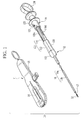
- a multiple clip applicator system 10 or application apparatus includes a multiple clip package 11 or cartridge and a handle device 12.
- the multiple clip package 11 includes a housing 14 or barrel and a coupling device 15.
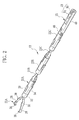
- a multiple clip assembly 13 or clip train of Fig. 2 is constituted by fastening plural clip devices.
- the housing 14 is a clip holder for holding and containing the multiple clip assembly 13.
- the coupling device 15 as a body of the multiple clip package 11 introduces the multiple clip assembly 13 from the housing 14 for loading of the multiple clip assembly 13 on the handle device 12.
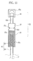
- the handle device 12 includes a cylindrical flexible sheath 16, an operating wire 17 and a wire handle 18.
- the flexible sheath 16 is loaded with the multiple clip assembly 13 from the coupling device 15.
- the operating wire 17 is inserted through the flexible sheath 16, and coupled with a proximal end of the multiple clip assembly 13.
- the wire handle 18 moves the operating wire 17 relative to the flexible sheath 16, for operating clips of the multiple clip assembly 13 for tissue clamping.
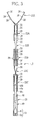
- the multiple clip assembly 13 includes three hemostatic clip devices 21A, 21B and 21C, three tubular shells 22A, 22B and 22C or rings for retention, and a fastening clip device 23 or dummy clip device for retention.
- the clip devices 21A-21C are used for tissue clamping with an endoscope.
- the tubular shells 22A-22C are set about the clip devices 21A-21C.
- the fastening clip device 23 is connected with a proximal end of the clip device 21C.
- the clip devices 21A-21C are connected in series as a clip train.
- the tubular shells 22A-22C retain the connected state between the clip devices 21A-21C.
- the fastening clip device 23 is used for coupling with the operating wire 17.
- a hemostatic clip device 21 constitutes each of the clip devices 21A-21C in an equal form.
- a tubular shell 22 constitutes each of the tubular shells 22A-22C in an equal form.
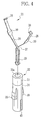
- two claws 26 are formed with the clip device 21.
- an elongate strip of a single plate is bent at an angle of 180 degrees. Segment portions extending at ends of the strip are crossed over one another, and opposed to one another by curving, to define the claws 26.
- the clip device 21 includes a crossover portion 27, arms 28 and a turn 29.
- the crossover portion 27 is defined by crossing the strip.
- the arms 28 are located at the free ends.
- the turn 29 is constituted by the closed end.
- Side projections 30 are formed on edges of the arms 28, are positioned at an intermediate point, and partially define portions with a greater width.
- the claws 26 of the clip device 21 When the claws 26 of the clip device 21 are free without receiving external force, the claws 26 are open and away from one another. The claws 26 become meshed with one another and are in a closed position for tissue clamping when the arms 28 are deformed toward one another.
- the claws 26 are a V-shaped projection and notch in the combination for the purpose of clamping body tissue.
- An example of material for the clip device 21 is metal with biocompatibility, for example stainless steel SUS 631 for springs.
- the tubular shell 22 has a cylindrical shape with a cavity for insertion of the clip device 21.
- the tubular shell 22 includes a push sleeve 33 and a support sleeve 34.
- the push sleeve 33 clamps and closes the claws 26.
- the support sleeve 34 retains a fastened state of the clip device 21.
- the push sleeve 33 of metal is fitted on the support sleeve 34 at its distal end.
- a narrow bore 33a is formed inside the push sleeve 33.
- a diameter of the narrow bore 33a is greater than a partial width of the clip device 21 at the crossover portion 27, and smaller than a width of the area of the side projections 30.
- An example of material for the push sleeve 33 is metal with biocompatibility, for example stainless steel SUS 304.
- the push sleeve 33 is set in an initial position to cover the crossover portion 27.
- the arms 28 are in an open state when the push sleeve 33 is in its initial position.
- the push sleeve 33 with the narrow bore 33a pushes the arms 28 when moved to a position of contacting the side projections 30, to clamp and close the claws 26.
- the claws 26 exert force of clamping when the arms 28 are pushed toward one another.
- a bore 34a is formed through the support sleeve 34 for receiving the turn 29 and the arms 28 of the clip device 21.
- a preferable example of the material for the support sleeve 34 is polyphenylsulfone (PPSU or PPS) as resin having biocompatibility and flexibility, so as to deform resiliently according to steering of a guide tube of an endoscope.
- Two fins 39 or skirt portions are formed on a peripheral surface of the support sleeve 34.
- the fins 39 extend with an increasing diameter in a direction from the distal end toward the proximal end of the support sleeve 34.
- the fins 39 when free without receiving external force, are deployed with their resiliency, and when depressed, become stowed by entry in the support sleeve 34.
- the fins 39 clamp the clip device 21 contained in the support sleeve 34, and keep the clip device 21 positioned with the tubular shell 22 without an error.
- the fins 39 become open upon advance through the distal opening of the flexible sheath 16, to keep the tubular shell 22 stopped at the distal opening of the flexible sheath 16.
- two grooves 42 are formed in the bore 34a, located in the second region 38, opposed to one another, and positioned equally with the fins 39 in the rotational direction.
- the width of the grooves 42 is slightly greater than the maximum width of the arms 28 of the clip device 21, and smaller than the width of the area of the side projections 30.
- a distance between wall surfaces of the grooves 42 is equal to a sum of lengths of the claws 26 of the clip device 21 in the opening direction.
- a length of the second region 38 is substantially equal to a distance at which the push sleeve 33 moves from the initial position of the clip device 21 toward its distal end to contact the side projections 30, namely a distance required for terminating clamping of the clip device 21. Also, the length of the second region 38 is substantially equal to a length of a portion of the clip device 21 from the claws 26 to an upper end of the side projections 30.
- Two end channels 45 are formed in the second region 38, and disposed with a difference from the fins 39 with an angle of 90 degrees.
- the end channels 45 make the tubular shell 22 flexible.
- the fastening clip device 23 includes a clip 48 and a mating structure 49.
- the clip 48 may be produced from a material the same as that for the clip devices 21.
- a pair of arms 48a of the clip 48 are defined by bending a single elongate strip of a metal plate.
- the arms 48a are in an open state if free without external force.
- claws 48b are formed with ends of the arms 48a.
- Side projections 48c are formed with intermediate portions of the arms 48a.
- the mating structure 49 is a rod-shaped part formed from the same material as the support sleeve 34 in the tubular shell 22.
- a support recess 49a is formed in a distal end of the mating structure 49 for receiving the clip 48 and keeping the arms 48a movable for opening and closing.
- a fitting connector 53 or press-fit connector is disposed at a proximal end of the mating structure 49 for mating with the operating wire 17.
- a shaft head 52 for hooking or press-fit at a distal end of the operating wire 17 is coupled with the fitting connector 53.
- the fitting connector 53 includes a pair of cavity walls 54 with resiliency, and a pair of clamping walls 55.
- a press-fit opening is defined between the cavity walls 54 and the clamping walls 55.
- the cavity walls 54 are resilient in the radial direction of the mating structure 49.
- the clamping walls 55 are located at the end of the cavity walls 54.
- the shaft head 52 includes a first hook projection 56, and a second hook projection 57 disposed on a proximal side from the first hook projection 56.
- the first hook projection 56 has a shape of substantially a quadrangular pyramid, and is inserted between the cavity walls 54 by moving laterally or crosswise to the axial direction of the mating structure 49.
- the second hook projection 57 has a cylindrical shape, and contacts a proximal end of the clamping walls 55.
- the second hook projection 57 has a peripheral groove 57a and a coil 58 both for appropriate mating of the shaft head 52 with the fitting connector 53.
- the peripheral groove 57a is formed in an outer surface of the second hook projection 57.
- the coil 58 is positioned at a proximal end of the second hook projection 57.
- a small diameter portion 57b is disposed at the proximal end of the second hook projection 57.
- the coil 58 is fitted around the small diameter portion 57b, and disposed around a distal end of the operating wire 17.
- the coil 58 has a diameter equal to that of the second hook projection 57, and flexibility enough for bending together with the operating wire 17.
- the multiple clip assembly 13 is constituted by connection of the clip devices 21A-21C, the tubular shells 22A-22C and the fastening clip device 23 in the following manner.
- the turn 29 of the clip device 21A is entered in the first region 37 of the tubular shell 22A through the narrow bore 33a.
- the clip device 21A is rotationally set with a difference of 90 degrees between an opening direction of the arms 28 and a deployment direction of the fins 39.
- the tubular shell 22A is set in the initial position where the push sleeve 33 covers the crossover portion 27 of the clip device 21A.
- a proximal end of the turn 29 protrudes into the second region 38.
- the arms 28 protrude externally from the tubular shell 22A and are in the open position.
- the arms 28 of the clip device 21B are inserted from the proximal end of the bore 34a.
- the clip device 21B is rotationally positioned with an angular difference of 90 degrees of the arms 28 from the clip device 21A in the first region 37, the arms 28 are inserted in the grooves 42.
- the clip device 21B entered in the second region 38 engages the claws 26 with the turn 29 of the clip device 21A.
- the clip device 21B is kept connected with the clip device 21A because the tubular shell 22A prevents the claws 26 of the clip device 21B from shifting toward the open position.
- the clip devices 21A and 21B and the tubular shell 22A are axially regulated owing to the resiliency of the arms 28 of the clip device 21B inside the tubular shell 22A toward the open position and the contact of the side projections 30 of the clip device 21B with a proximal end of the tubular shell 22A.
- the clip devices 21A and 21B and the tubular shell 22A are rotationally regulated owing to insertion of the arms 28 of the clip device 21B in the grooves 42 of the tubular shell 22A.
- Fastening of the clip device 21C to the clip device 21B, retention with the tubular shell 22B for fastening, fastening of the fastening clip device 23 to the clip device 21C, and retention with the tubular shell 22C for fastening are the same as the conditions of the clip devices 21A and 21B and the tubular shell 22A.
- the multiple clip package 11 having the multiple clip assembly 13 according to the invention is described next.
- the multiple clip package 11 includes the housing 14 and the coupling device 15.
- the housing 14 contains the multiple clip assembly 13 in a state of keeping the fins 39 deployed in the clip devices 21A-21C.
- the coupling device 15 draws the multiple clip assembly 13 from the housing 14, depresses and stows the fins 39, couples the operating wire 17 with the fastening clip device 23, and loads the flexible sheath 16 with the multiple clip assembly 13.
- the housing 14 is mounted on the coupling device 15 in a removable manner.
- a barrel cavity 60 is defined in the housing 14, and contains the multiple clip assembly 13.
- An outer diameter of the housing 14 is substantially equal to an outer diameter of the flexible sheath 16.
- An inner diameter of the barrel cavity 60 is substantially equal to the inner diameter of the flexible sheath 16.
- the housing 14 is constituted by a lower housing half 63 and an upper housing half 64 or barrel halves.
- An inner surface 63a of the lower housing half 63 and an inner surface 64a of the upper housing half 64 are semicylindrical, and combined to form the barrel cavity 60 of the cylindrical shape.
- the barrel cavity 60 is open at both of two ends, which include a first end for containing a distal end 14a with a distal opening or exit opening of the housing 14. The exit opening at the first end is open for advancing the multiple clip assembly 13 to the outside of the barrel cavity 60.
- the multiple clip assembly 13 is contained in the barrel cavity 60 while the first clip device 21A is disposed at a distal end 14a of the housing 14 and the arms 28 of the first clip device 21A are open and closed laterally in the horizontal direction.
- the first clip device 21A is set in the closed position by the inside of the barrel cavity 60.
- the clip devices 21A-21C are oriented with differences in the opening direction of the arms 28 with 90 degrees from one another. There is a difference between the claws 26 and the fins 39 in the opening direction with 90 degrees.
- the fins 39 of the tubular shells 22A and 22C are movable for deployment vertically in the depicted state.
- the fins 39 of the tubular shell 22B are movable for deployment horizontally in the depicted state.
- Fin receiving slots 67 are formed in the upper and lower housing halves 63 and 64 and receive the fins 39 deployed from the tubular shells 22A and 22C.
- Recesses are formed in edge portions of the upper and lower housing halves 63 and 64, and define fin receiving slots 68 when joined, so as to receive the fins 39 deployed from the tubular shell 22B. This is effective in setting the fins 39 free from the pressing force toward the stowed position inside the housing 14. The force of recovery of the fins 39 toward the deployed position can be kept without lowering.
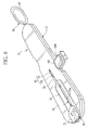
- a grip tab 71 is formed on an upper surface of the upper housing half 64 and positioned at its proximal end.
- the grip tab 71 has a concave surface for touch of a user's finger, and used for pull of the housing 14 out of the coupling device 15.
- the lower housing half 63 has plural ridges 74 and a key projection 75.
- the ridges 74 are four including two projecting from a distal end portion of the lower housing half 63 and two projecting from a proximal end portion of the same.
- the key projection 75 projects downwards.
- a concave surface 78 is formed in the coupling device 15, and disposed at its end with a reduced height.
- a stage groove 79 for housing reception is formed in a wall having the concave surface 78, has an inner diameter slightly greater than an outer diameter of the housing 14, and has an open upper side.
- the housing 14 is inserted in the stage groove 79.
- the housing 14 is removed from the stage groove 79 before inserting the flexible sheath 16 instead.
- An elongated slot 79a is a cavity extending from the stage groove 79, and causes the housing 14 or the flexible sheath 16 to appear in the concave surface 78.
- the housing 14 or the flexible sheath 16 mounted in the stage groove 79 is kept with the coupling device 15 through the elongated slot 79a.
- a receiving opening 82 is formed in the wall of the coupling device 15 and adjacent to the stage groove 79.
- the receiving opening 82 receives insertion of the operating wire 17 and the shaft head 52 after pulling of the multiple clip assembly 13 from the housing 14 into the coupling device 15, for mating the shaft head 52 with the mating structure 49 of the fastening clip device 23.
- the receiving opening 82 includes an access window 83 and a wire channel 84.
- the access window 83 receives insertion of the shaft head 52 in a direction perpendicular to the axial direction of the operating wire 17.
- the wire channel 84 receives insertion of the operating wire 17.
- the wire channel 84 extends to the stage groove 79 and also the access window 83.
- the access window 83 has a shape defined for pass through of the shaft head 52 as viewed in the transverse direction of the press-fit and greater than the same with a small difference.
- the access window 83 includes a first subsection 83a, a second subsection 83b and a third subsection 83c.
- the first subsection 83a receives the first hook projection 56.
- the second subsection 83b receives a portion of the operating wire 17 between the first and second hook projections 56 and 57.
- the third subsection 83c receives the second hook projection 57 and the coil 58.
- An internal projection 83d projects from an edge of the third subsection 83c for fitting in the peripheral groove 57a of the second hook projection 57, by way of a prevention device or keying device or anti-mismating device.
- the size of the access window 83 is only 0.1 mm greater than the profile of the shaft head 52 in relation of the total length of the peripheral edge. A shaft head having only a small difference in the shape cannot be inserted in the access window 83.
- the coupling device 15 is constituted by a lower casing 87 and an upper casing 88, each one of which has arcuate edges disposed at distal and proximal ends.
- the stage groove 79 and the elongated slot 79a are formed in respectively the lower casing 87 and the upper casing 88.
- a regulation groove 89 and a key way groove 90 are formed in a wall having the upper surface of the lower casing 87 and extend in an axial direction of the coupling device 15.
- the ridges 74 and the key projection 75 of the housing 14 are engaged with the regulation groove 89 and the key way groove 90.
- a fin bending channel 93 for closing is defined inside the coupling device 15 and positioned inwards from the stage groove 79 in a cylindrical shape.
- the fin bending channel 93 as a stage structure of the invention has a bore equal to that of the flexible sheath 16 and the barrel cavity 60, and is axially registered with the housing 14 inserted in the stage groove 79.
- An inner surface of the fin bending channel 93 is set in registration with that of the housing 14 and the flexible sheath 16 in the stage groove 79.
- the fin bending channel 93 contains the multiple clip assembly 13 entered from the barrel cavity 60, and depresses and stows the fins 39 with its inner surface.
- the receiving opening 82 described above is connected with the fin bending channel 93 inside the coupling device 15.
- a pull rod structure 96 is assembled with the coupling device 15.
- the coupling device 15 introduces the multiple clip assembly 13 from the housing 14 into the fin bending channel 93 when guided by the pull rod structure 96.
- the pull rod structure 96 includes a pull tab 97, a shank 98 and an end connector 99.
- the pull tab 97 protrudes from the coupling device 15 in its longitudinal direction, and has an elliptic shape.
- the shank 98 extends from the pull tab 97.
- the end connector 99 is formed with an end of the shank 98 (See Fig. 12 ) .
- the shank 98 is inserted in the fin bending channel 93 with its length enough for penetration.
- the end connector 99 is inserted in the barrel cavity 60, and engaged with the first clip device 21A.
- a release groove 102 is formed to extend horizontally from the fin bending channel 93.
- a slide channel 105 or auxiliary path is formed through a lateral wall of the coupling device 15, and extends in a direction perpendicular with the fin bending channel 93 under the receiving opening 82.
- the slide channel 105 extends in the transverse direction of the coupling device 15 toward its second lateral wall.
- the guide slider 106 is one piece molded from a plastic material, and includes a button head 109, a lower slide plate 110 and an upper slide plate 111.
- the button head 109 is operable for depression into the slide channel 105.
- the slide plates 110 and 111 are opposed to one another, and extend from the button head 109 horizontally.
- a main portion of the guide slider 106 protrudes laterally from the coupling device 15. See Fig. 8 .
- the pull rod structure 96 pulls the multiple clip assembly 13 into the fin bending channel 93 to insert the flexible sheath 16 into the stage groove 79 in place of the housing 14 and insert the operating wire 17 and the shaft head 52 in the receiving opening 82, then the guide slider 106 is pushed into the slide channel 105. Then the upper and lower slide plates 110 and 111 of the guide slider 106 come to sandwich the mating structure 49 and the shaft head 52 in a vertical direction. The first hook projection 56 and the operating wire 17 are pressed into the press-fit opening between the cavity walls 54 and the clamping walls 55, to couple the multiple clip assembly 13 with the operating wire 17.
- the handle device 12 includes the flexible sheath 16, the operating wire 17 and the wire handle 18.
- An example of the flexible sheath 16 is a flexible coil sheath in which a wire of metal is tightly wound in a coiled form.
- the flexible sheath 16 includes an inner tube 16a for wire insertion and an outer sleeve 16b for clip setting.
- the inner tube 16a is connected with the wire handle 18.
- the outer sleeve 16b is disposed at a distal end as free end.
- the inner tube 16a has an inner diameter sufficient for insertion of the operating wire 17, and constitutes a main part of the flexible sheath 16.
- the outer sleeve 16b has an inner diameter for disengaging the turn 29 of the clip device 21 from the claws 26 of a succeeding one of the clip devices 21.
- An inner diameter of the outer sleeve 16b is greater than a sum of a length of the claws 26 and a width of a portion of the turn 29 for engagement with the claws 26.
- the operating wire 17 is a part of metal, and inserted through the flexible sheath 16 and the wire handle 18 movably back and forth.
- the shaft head 52 of Fig. 7 is secured to a distal end of the operating wire 17.
- a proximal end of the first hook projection 56 pushes the clamping walls 55 to transmit force of pulling to the multiple clip assembly 13.
- a peripheral surface of the first hook projection 56 transmits rotations of the operating wire 17 to the cavity walls 54.
- a distal end of the second hook projection 57 pushes a proximal end of the clamping walls 55, and transmits force of push to the multiple clip assembly 13.
- the wire handle 18 includes a sheath handle 120, a slide mechanism 121, a regulating portion 122 and a sliding finger flange 123.
- the sheath handle 120 has a cylindrical shape.
- the slide mechanism 121 is mounted about the sheath handle 120 in a rotatable manner.
- the regulating portion 122 is a mechanism for regulating a stop position of the slide mechanism 121.
- the sliding finger flange 123 is mounted about the slide mechanism 121 and slidable in an axial direction.
- a thumb ring 124 is formed with a proximal end of the sheath handle 120. For example, a thumb of an operator or doctor is inserted in the thumb ring 124. His or her index finger and middle finger push the sliding finger flange 123 to slide the wire handle 18.
- a through hole and a slide groove are formed in the sheath handle 120.
- the through hole extends in the axial direction.
- the slide groove extends axially from the outer surface to the through hole.
- the operating wire 17 is inserted in the through hole.
- a guide pin 127 for sliding is fixed on the sliding finger flange 123, and inserted in the slide groove.
- a proximal end of the operating wire 17 is retained on the guide pin 127.
- the slide mechanism 121 has a sliding tube 131 and a guide barrel 132.
- Four guide grooves 130a, 130b, 130c and 130d are formed in the sliding tube 131, extend in the axial direction, and are positioned rotationally regularly.
- the guide barrel 132 rotates the sliding tube 131 about the sheath handle 120.
- the slide groove of the sheath handle 120 is set on a selected one of the guide grooves 130a-130d.
- the guide grooves 130a-130d have different lengths, any one of which is smaller than the length of the slide groove. An amount of sliding of the sliding finger flange 123 is changed according to one of the guide grooves 130a-130d where the slide groove is set.
- the sliding tube 131 is illustrated in a developed state.
- the guide pin 127 is in a home position (HP) out of the guide grooves 130a-130d.
- the guide groove 130a has a greatest length, and is used for loading the flexible sheath 16 with the multiple clip assembly 13 from the coupling device 15, or for removing the fastening clip device 23 from the operating wire 17 after use.
- the sliding finger flange 123 is slid for the guide pin 127 to contact an end of the guide groove 130a, the operating wire 17 and the shaft head 52 come to protrude from the distal opening of the flexible sheath 16.
- the guide groove 130b with the smallest length is used for tissue clamping with the first clip device 21A.
- the moving amount of the operating wire 17 is small because the first clip device 21A is disposed near to the distal opening of the flexible sheath 16.
- the guide grooves 130c and 130d are used for tissue clamping with respectively the clip devices 21B and 21C owing to greater lengths than the guide groove 130b.
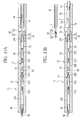
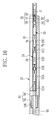
- FIGs. 14A-16 A method of loading of the multiple clip assembly 13 in the flexible sheath 16 from the multiple clip package 11 is described by referring to Figs. 14A-16 .
- the housing 14 and the coupling device 15 are retained together by use of the concave surface 78 to pull the pull tab 97 from the coupling device 15.
- the shank 98 is pulled out of the coupling device 15.
- the end connector 99 following the shank 98 moves into the fin bending channel 93.
- the multiple clip assembly 13 is pulled from the barrel cavity 60 into the fin bending channel 93 by the end connector 99.
- the fins 39 of the tubular shells 22A-22C are depressed and stowed by the inside of the fin bending channel 93.
- the tubular shells 22A-22C are regulated by contact of their proximal end on the side projections 30 of one of the clip devices 21B and 21C, no error in positioning will occur between the clip devices 21A-21C and the tubular shells 22A-22C.
- the arms 28 of the clip device 21A become released, to disengage the claws 26 from the end connector 99.
- the multiple clip assembly 13 is stopped in a position to set the fitting connector 53 of the mating structure 49 exactly at the access window 83 of the receiving opening 82.
- the housing 14 is moved away from the stage groove 79 in an axial direction.
- the guide groove 130a of the sliding tube 131 is positioned on the slide groove in the handle device 12.
- the sliding finger flange 123 is slid to a slide position where the guide pin 127 contacts an end of the guide groove 130a.
- the operating wire 17 and the shaft head 52 protrude from a distal opening of the flexible sheath 16.
- Fig. 14B the flexible sheath 16 is inserted in the stage groove 79 in place of the housing 14.
- the operating wire 17 and the shaft head 52 are inserted in the receiving opening 82 in a downward direction relative to the coupling device 15. After their insertion, the flexible sheath 16 and the coupling device 15 are retained together by use of the concave surface 78.
- Fig. 15B the shaft head 52 is mated by press-fit with the fitting connector 53.
- the access window 83 of the receiving opening 82 is slightly larger than the profile of the shaft head 52 for its pass through. In the access window 83, it is impossible to insert another shaft head with a different shape from that of the shaft head 52. This is effective in preventing mismatch of the multiple clip assembly 13.
- Fig. 15B the guide slider 106 is pushed into the slide channel 105.
- the upper and lower slide plates 110 and 111 on the guide slider 106 squeeze the shaft head 52 and the fitting connector 53 vertically.
- the first hook projection 56 and the operating wire 17 becomes fitted in the press-fit opening between the cavity walls 54 and the clamping walls 55.
- the second hook projection 57 contacts a proximal end of the mating structure 49.
- the operating wire 17 becomes coupled with the multiple clip assembly 13.
- the sliding finger flange 123 is slid in the proximal direction to move the guide pin 127 to the home position HP from the end of the guide groove 130a.
- the operating wire 17 is pulled to introduce the multiple clip assembly 13 into the flexible sheath 16 by advancing its proximal end.
- the inside of the flexible sheath 16 is in registration with the fin bending channel 93.
- the multiple clip assembly 13 can be moved only with a small resistance, because the fins 39 are depressed and stowed.
- the multiple clip assembly 13 can be loaded on the flexible sheath 16 without an error in positioning the clip devices 21A-21C and the tubular shells 22A-22C.
- the flexible sheath 16 is moved away from the flexible sheath 16 after loading of the multiple clip assembly 13.
- Fig. 17A Tissue clamping by use of the multiple clip assembly 13 is described now.
- the flexible sheath 16 having the outer sleeve 16b loaded with the multiple clip assembly 13 is inserted in an instrument channel in an endoscope entered in a body.
- a distal end of the flexible sheath 16 is advanced through a distal opening of the endoscope, and accesses affected tissue.
- the guide groove 130b of the sliding tube 131 is positioned on the slide groove in the handle device 12.
- the sliding finger flange 123 is slid to a slide position where the guide pin 127 contacts an end of the guide groove 130b.
- the first clip device 21A and the tubular shell 22B become protruded from the distal opening of the flexible sheath 16 by the operating wire 17.
- the arms 28 of the first clip device 21A become open by the resiliency.
- the fins 39 of the tubular shell 22A become deployed and engaged with the distal opening of the flexible sheath 16. Now the first clip device 21A is ready for use.
- the entirety of the wire handle 18 is moved to press the claws 26 of the first clip device 21A in the open position against affected tissue. Then the sliding finger flange 123 is slid in the proximal direction to pull the operating wire 17 at a predetermined amount. In response, the clip devices 21A-21C are pulled equally in a state engaged serially from the fastening clip device 23.
- the clip device 21A is released from push with the fins 39.
- the tubular shell 22A is prevented from moving back into the flexible sheath 16 by the fins 39.
- the clip device 21A is moved relative to the tubular shell 22A in the proximal direction by pull of the operating wire 17.
- the push sleeve 33 is pressed to a position directly under the side projections 30 of the clip device 21A, the clip device 21A is closed entirely by the tubular shell 22A.
- an engaged portion between the clip devices 21A and 21B is moved out of the proximal end of the tubular shell 22A.
- the arms 28 of the clip device 21B become open to contact the inside of the flexible sheath 16 by their resiliency.
- An interval between the claws 26 becomes greater than a width of the turn 29 of the clip device 21A, to disengage the clip device 21A from the clip device 21B.
- the entirety of the wire handle 18 is pulled to move the distal opening of the flexible sheath 16 back from the affected tissue.
- the clip device 21A and the tubular shell 22A are separated from the distal opening of the flexible sheath 16.
- tissue clamping by use of the clip devices 21B and 21C is carried out.
- the multiple clip applicator system 10 of the invention has the clip devices 21 of three sizes which are short, medium and long sizes with different lengths of arms. Any one of the three can be selected for use with affected tissue by consideration of its size.
- a plurality of the tubular shells 22 are prepared in consideration of the sizes of the clip devices 21.
- a hemostatic clip device 21M of a medium size is illustrated, and has arms 28M of a standard length.
- a second region in a support sleeve 34M has a size corresponding to the arms 28M in a tubular shell 22M for use with the clip device 21M.
- a total length of the tubular shell 22M is LM.
- the clip device 21M is structurally the same as the clip device 21 described above.
- the tubular shell 22M is structurally the same as the tubular shell 22.
- a hemostatic clip device 21S of a short size is illustrated. Arms 28S of the clip device 21S are shorter than those of the clip device 21M. An interval WS between claws 26S of the clip device 21S upon opening of the arms 28S is shorter than an interval WM between those of the clip device 21M, so that the clip device 21S is suitable for clamping of tissue of a small size.
- a tubular shell 22S is for use with the clip device 21S.
- a second region of a support sleeve 34S of the tubular shell 22S is longer than that of the support sleeve 34M in association with the arms 28S.
- a total length LS of the tubular shell 22S satisfies the condition LM > LS.
- a hemostatic clip device 21L of a long size is illustrated. Arms 28L of the clip device 21L are longer than those of the clip device 21M. An interval WL between claws 26L of the clip device 21L upon opening of the arms 28L is longer than an interval WM between those of the clip device 21M, so that the clip device 21L is suitable for clamping of tissue of a large size.
- a tubular shell 22L is for use with the clip device 21L.
- a second region of a support sleeve 34L of the tubular shell 22L is longer than that of the support sleeve 34M in association with the arms 28L.
- a total length LL of the tubular shell 22L satisfies the condition LL > LM > LS.
- the multiple clip applicator system 10 includes three multiple clip assemblies 13S, 13M and 13L or clip trains which respectively have the clip devices 21S, 21M and 21L and the tubular shells 22S, 22M and 22L.
- fastening clip devices 23S, 23M and 23L or dummy clip devices are used with respectively the multiple clip assemblies 13S, 13M and 13L.
- Clips 48S, 48M and 48L in the fastening clip devices 23S, 23M and 23L are different in the position for contact of the side projections 48c with a proximal end of the tubular shells 22S, 22M and 22L.
- the mating structure 49 is commonly included in each of the fastening clip devices 23S, 23M and 23L.
- the fastening clip device 23M is structurally the same as the fastening clip device 23.
- the multiple clip applicator system 10 of the invention has three types of the multiple clip package 11 of which the housing 14 and the coupling device 15 are structurally specialized for types of the clip assemblies.
- the positions of the fin receiving slots 67 and 68 are different in compliance with the positions of the fins 39 of the tubular shells 22S, 22M and 22L.
- the coupling device 15 the position of the release groove 102, the length of the pull rod structure 96 and the like are different in compliance with the total lengths of the multiple clip assemblies 13S, 13M and 13L.
- the multiple clip assemblies 13S, 13M and 13L are different from one another in the stroke of the operating wire 17 for tissue clamping.
- the slide mechanism 121 is used in the multiple clip applicator system 10 with the guide grooves 130a-130d which have different lengths according to the multiple clip assemblies 13S, 13M and 13L.
- the multiple clip assembly 13L of the long size may be combined with the handle device 12 for the short size.
- An amount of the advance of the clip device 21 relative to the flexible sheath 16 may be too great or too small. Failure in operation may occur, for example, the arms 28 of the clip device 21 do not open suitably, or fastening may be released before tissue clamping.
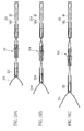
- the multiple clip applicator system 10 of one preferred embodiment of Figs. 20A-20C includes shaft heads 52S, 52M and 52L for hooking or press-fit and receiving openings 83S, 83M and 83L in combination in consideration of the multiple clip assemblies 13S, 13M and 13L.
- the mating structure 49 is a common element between the multiple clip assemblies 13S, 13M and 13L. So the first hook projection 56 is common between the shaft heads 52S, 52M and 52L.
- the first subsection 83a for insertion of the first hook projection 56 is the same between the receiving openings 83S, 83M and 83L.
- FIG. 20B the shaft head 52M corresponding to the multiple clip assembly 13M of the medium size is illustrated.
- a peripheral groove 57Ma is formed in a second hook projection 57M and near to its proximal end.
- a small diameter portion 57Mb is formed at a proximal end of the second hook projection 57M.
- the coil 58 is fitted on the small diameter portion 57Mb.
- the receiving opening 83M corresponding to the multiple clip assembly 13M of the medium size has a third subsection 83Mc for insertion.
- the third subsection 83Mc has a shape near to that of the second hook projection 57M and the coil 58.
- Two internal projections 83Md are formed with edges of the third subsection 83Mc for insertion into the peripheral groove 57Ma. Note that the shaft head 52M and the receiving opening 83M are structurally the same as the shaft head 52 and the receiving opening 82 with the access window 83.
- FIG. 20A the shaft head 52S corresponding to the multiple clip assembly 13S of the short size is illustrated.
- a peripheral groove 57Sa is formed in a second hook projection 57S structurally the same as the second hook projection 57M, and near to its proximal end.
- a small diameter portion 57Sb is formed at a proximal end of the second hook projection 57S.
- the coil 58 is fitted on the small diameter portion 57Sb.
- the receiving opening 83S corresponding to the multiple clip assembly 13S of the short size has a third subsection 83Sc for insertion.
- the third subsection 83Sc has a shape near to that of the second hook projection 57S and the coil 58.
- Two internal projections 83Sd are formed with edges of the third subsection 83Sc for insertion into the peripheral groove 57Sa, by way of a prevention device or keying device or anti-mismating device.
- the shaft head 52L corresponding to the multiple clip assembly 13L of the long size is cylindrical, and has a diameter equal to that of the second hook projections 57S and 57M. No peripheral groove is formed in the shaft head 52L.
- a second hook projection 57L has a proximal end where an inclined portion 57La is formed to have a decreasing diameter in a proximal direction.
- a total length of the second hook projection 57L is equal to that of the second hook projections 57S and 57M inclusive of the small diameter portions 57Sb and 57Mb.
- a third subsection 83Lc for insertion has a form near to the profile of the second hook projection 57L and enough to cover the same.
- the third subsection 83Lc is shorter than the third subsections 83Sc and 83Mc as the shaft head 52L is not provided with the coil 58.
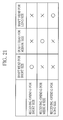
- Fig. 21 compatibility of the shaft heads 52S, 52M and 52L to the receiving openings 83S, 83M and 83L is indicated.
- a symbol of o denotes a matched status.
- a symbol of x denotes an unmatched status.
- the shaft heads 52S and 52M cannot be inserted in the third subsection 83Lc for the long size because of having the coil 58.
- the shaft head 52L cannot be inserted in any one of the third subsections 83Sc and 83Mc because the second hook projection 57L interferes with the internal projections 83Sd and 83Md.
- the shaft heads 52S and 52M are different from one another in relation to the positions of the peripheral grooves 57Sa and 57Ma and the internal projections 83Sd and 83Md. Even when one of the peripheral grooves is shifted for pass through of one of the internal projections, the first hook projection 56 operates for interference. Pass through of those with the receiving openings 83S and 83M is impossible. Thus, mismatch of the multiple clip assembly 13 on the handle device 12 can be prevented.
- peripheral grooves in the second shaft head and internal projections in the receiving opening are changed for types of the clip assemblies. Furthermore, it is possible to change the numbers of the peripheral grooves and internal projections or their size. Also, the number, width and length of the second shaft head may be changed.
- a second hook projection 141S in a shaft head 140S for the short size has a long and thin shape. Also, a shaft head 140M for the medium size has two second hook projections 141M. A shaft head 140L for the long size has three second hook projections 141L. The second hook projections 141M and 141L have forms with a greater thickness and smaller length than that of the shaft head 140S.
- Receiving openings 142S, 142M and 142L are defined for insertion of respectively the shaft heads 140S, 140M and 140L, and have a slightly greater size than matched shaft heads. Thus, mismatch can be prevented in a manner similar to the above embodiments.
- the number of parameters of structures of shaft heads in different forms may be equal to or more than the number of types of the clip assemblies.
- the types of the clip assemblies are different according to different sizes of the clip devices.
- forms of the shaft head and the receiving opening can be changed according to types of the clip assemblies being different in the number of serially connected clip devices therein.
- Various modifications are possible for the clip device package and multiple clip applicator system according to the invention.
Landscapes
- Health & Medical Sciences (AREA)
- Surgery (AREA)
- Life Sciences & Earth Sciences (AREA)
- Heart & Thoracic Surgery (AREA)
- Nuclear Medicine, Radiotherapy & Molecular Imaging (AREA)
- Vascular Medicine (AREA)
- Engineering & Computer Science (AREA)
- Biomedical Technology (AREA)
- Reproductive Health (AREA)
- Medical Informatics (AREA)
- Molecular Biology (AREA)
- Animal Behavior & Ethology (AREA)
- General Health & Medical Sciences (AREA)
- Public Health (AREA)
- Veterinary Medicine (AREA)
- Surgical Instruments (AREA)
Abstract
A multiple clip applicator system for tissue clamping of hemostasis includes clip devices (21, 21A-21C, 21S, 21M, 21L) of a train and a flexible sheath (16). To load the flexible sheath with clip devices, a coupling device (15) is used. A shaft head (52, 52S, 52M, 52L, 140, 140S, 140M, 140L) is positioned on an operating wire (17) in the flexible sheath. A receiving opening (82, 83S, 83M, 83L, 142S, 142M, 142L) is formed in the coupling device, for receiving insertion of the shaft head, for mating by press-fit with the fastening clip device (23). The shaft head is a selected one of plural shaft heads which are different in a shape according to the plural multiple clip assemblies (13). The receiving opening is a selected one of plural receiving openings having a shape according to corresponding shapes of the plural shaft heads, and adapted to preventing a second shaft head from entry in a first receiving opening and preventing a first shaft head from entry in a second receiving opening.
Description
- The present invention relates to a clip package, multiple clip applicator system, and prevention device for preventing mismatch. More particularly, the present invention relates to a clip package which includes a train of plural clip devices and in which mismatch of a multiple clip assembly on a handle device is prevented, and multiple clip applicator system, and prevention device for preventing mismatch.
- An applied use of an endoscope is known in the field of medicine, and used for treatment by entry of a long medical instrument in a patient's body. Tissue clamping is known as treatment of affected tissue with the endoscope, in which affected tissue in the body is clamped by a clip device, for example hemostasis. A pair of arms are included in the clip device, constituted by bending a strip of metal, and shiftable between open and closed positions. In a free state, the arms become open with the resiliency of the strip. Claws are formed at distal ends of the arms, for mesh with one another when closed.
- In a clip device applicator system, a handle device includes a flexible sheath and an operating wire. The flexible sheath is loaded with the clip device. The operating wire is coupled with a proximal end of the clip device within the flexible sheath. The flexible sheath with the clip device is entered in the body through an instrument channel which is defined within the endoscope. When the operating wire is pulled, the clip device is moved to protrude from a distal opening of the flexible sheath. The arms are opened in the clip device with their resiliency. When the claws of the clip device is pressed on the affected tissue, the operating wire is pulled. The distal opening of the flexible sheath or a tubular shell about the clip device closes the clip device, which is separated from the operating wire.
-
U.S.P. No. 6,814,742 (corresponding toJP-A 2007-222649 - It is preferable for the clip device to have as small a size as possible because of small influence to a body. However, tissue clamping may be impossible with a small size of the clip device as there are various sizes of affected tissue. Thus, a plurality of types of clip devices with different sizes are prepared in a system of a known clip applicator. An operator or doctor can select one of the clip devices with a suitable size according to the affected tissue or the like. Note that the size of the clip devices means a length of arms, or a width of opening of the arms. Examples of the sizes is a standard size, long size and short size.
- The well-known one-shot type of the clip applicator (See
U.S.P. No. 6,814,742 corresponding toJP-A 2007-222649 U.S.P. No. 7,081,121 (corresponding toJP-A 2002-272751 - Also, a multiple clip package has been suggested in the field of tissue clamping for the purpose of easily loading the flexible sheath with a plurality of the clip devices. The clip package includes a multiple clip assembly or clip train, which includes a plurality of the clip devices connected to one another, and is contained in the housing. The clip package operates for loading the flexible sheath with the multiple clip assembly from the housing.
- In the multiple clip applicator, a moving amount or stroke of the operating wire is different according to a sequence or positions of connecting the clip devices within the multiple clip assembly for the purpose of advancing the clip devices through a distal opening of the flexible sheath. For example, a handle device is constructed to advance the clip devices by moving the operating wire in a distal direction from its home position. The moving amount or stroke of the operating wire is greater for a final one of the clip devices than a first one of the clip devices. Also, the moving amount or stroke of the operating wire is influenced by a size of the clip devices, and differs between the types of the clip devices with the short, medium and long sizes.
- In the clip applicator of the one-shot type, a doctor or operator moves the operating wire by observing an image obtained by the endoscope. However, the moving amount or stroke of the operating wire for the multiple clip applicator is different for each of the clip devices for the purpose of the tissue clamping. Much care must be taken for operating the multiple clip applicator. In consideration of this problem, it is necessary to change over the moving amount or stroke of the operating wire by use of the handle device according to the position of the clip devices in the multiple clip assembly. Also, the handle device of a plurality of types may be conceivable for the multi size system with the short, medium and long sizes of the clip devices.
- When plural types of multiple clip assemblies are combined with plural types of handle devices, there occurs a problem of mismatch in that one of the handle device is loaded with an incorrect one of the multiple clip assembly. In such a situation, the distance of advancing the clip device relative to the flexible sheath is insufficient or excessive. Failure occurs in that the arms of the clip device do not open suitably, or that the clip device is disconnected unsuitably before the tissue clamping.
- As the clip devices have as small a length as several millimeters, it is highly difficult to discern the size of the clip devices by observing the appearance. If colors of the housing are predetermined distinctly for the types of the clip devices, prevention of mismatch cannot be complete. Types of the clip devices may be indicated on a surface of the housing and the handle device, but with a limit for effectively preventing mismatch. There is no suggestion of prevention of mismatch in the documents of
U.S.P. No. 6,814,742 (corresponding toJP-A 2007-222649 U.S.P. No. 7,081,121 (corresponding toJP-A 2002-272751 - In view of the foregoing problems, an object of the present invention is to provide a clip package which includes a train of plural clip devices and in which mismatch of a multiple clip assembly on a handle device is prevented, and multiple clip applicator system, and prevention device for preventing mismatch.
- In order to achieve the above and other objects and advantages of this invention, a clip package is provided, and includes a multiple clip assembly having plural clip devices connected with one another in a train by use of claws positioned at distal ends of openable arms, a fastening clip device connected with a final one of the clip devices, and a fitting connector, disposed on the fastening clip device, for mating with a shaft head in a direction transverse to a direction of the train of the clip devices at a distal end of an operating wire for operating the clip devices. A housing contains the multiple clip assembly. There is a coupling device including a stage portion for introducing the multiple clip assembly from the housing, to enable coupling with a flexible sheath through which the operating wire extends. A receiving opening has a form slightly larger than a profile of the shaft head and a portion of the operating wire as viewed in the transverse direction, for receiving insertion of the shaft head and the portion of the operating wire to mate the shaft head with the fitting connector on the stage portion. The coupling device operates upon pull of the operating wire after mating the shaft head with the fitting connector, to enter the multiple clip assembly from the stage portion into the flexible sheath in a proximal direction thereof.
- Also, a multiple clip applicator system is provided, and includes a multiple clip assembly having plural clip devices connected with one another in a train by use of claws positioned at distal ends of openable arms, a fastening clip device connected with a final one of the clip devices, and a fitting connector, disposed on the fastening clip device, for mating with a shaft head in a direction transverse to a direction of the train of the clip devices at a distal end of an operating wire for operating the clip devices. The multiple clip applicator system includes a housing for containing the multiple clip assembly. There is a coupling device including a stage portion for introducing the multiple clip assembly from the housing, to enable coupling with a flexible sheath through which the operating wire extends. A receiving opening has a form slightly larger than a profile of the shaft head and a portion of the operating wire as viewed in the transverse direction, for receiving insertion of the shaft head and the portion of the operating wire to mate the shaft head with the fitting connector on the stage portion. The coupling device operates upon pull of the operating wire after mating the shaft head with the fitting connector, to enter the multiple clip assembly from the stage portion into the flexible sheath in a proximal direction thereof. A handle device moves the operating wire relative to the flexible sheath with stroke according to a length of the arms and a sequence of the train, to carry out treatment with each one of the clip devices in the multiple clip assembly.
- The multiple clip assembly is a selected one of at least first and second multiple clip assemblies which are different in at least one of a length of the arms and a number of the clip devices in the train. The shaft head is a selected one of first and second shaft heads which are different in a shape in association with the first and second multiple clip assemblies. The receiving opening is selected from first and second receiving openings according to the first or second shaft head. Furthermore, a prevention device is positioned in at least one of the first and second receiving openings, for preventing the second shaft head from entry in the first receiving opening, and preventing the first shaft head from entry in the second receiving opening.
- The handle device is a selected one of first and second handle devices which are different in stroke of the shaft head and the operating wire in association with respectively the first and second multiple clip assemblies. The coupling device is a selected one of first and second coupling devices having respectively the first and second receiving openings.
- The shaft head includes a first hook projection, having a common shape between the first and second multiple clip assemblies, for engagement with the fitting connector. A second hook projection has a shape different between the first and second multiple clip assemblies.
- The second hook projection is positioned on a proximal side from the first hook projection.
- The second hook projection includes at least one peripheral groove of which a position, number or size is different between the first and second multiple clip assemblies. The prevention device includes an internal projection, formed with each of the first and second receiving openings, for insertion in the peripheral groove.
- The second hook projection includes a coil associated with at least one of the first and second multiple clip assemblies, and disposed about a distal end of the operating wire. The receiving opening has a width for passing the coil.
- In one preferred embodiment, the second hook projection is in a drum shape, and has a difference between the first and second multiple clip assemblies in at least one of a number, outer diameter and length thereof.
- The at least first and second multiple clip assemblies include a multiple clip assembly of a standard size, a multiple clip assembly of a long size having the clip devices of which the arms are longer than the arms in the standard size, and a multiple clip assembly of a short size having the clip devices of which the arms are shorter than the arms in the standard size.
- Also, a prevention device for preventing mismatch in a multiple clip applicator system is provided. The multiple clip applicator system includes a multiple clip assembly having plural clip devices and a fastening clip device, the clip devices being connected with one another in a train by use of claws positioned at distal ends of openable arms, the fastening clip device being connected with a final one of the clip devices. A handle device has a flexible sheath. A coupling device contains the multiple clip assembly and loading the flexible sheath with the multiple clip assembly. The multiple clip assembly is a selected one of at least first and second multiple clip assemblies which are different in at least one of a length of the arms and a number of the clip devices in the train, the coupling device is selected from first and second coupling devices according to the first or second multiple clip assembly, and the handle device is selected from first and second handle devices according to the first or second multiple clip assembly. The prevention device includes a shaft head, selected from first and second shaft heads which are different in a shape according to the first and second multiple clip assemblies, positioned on an operating wire in the flexible sheath. A receiving opening is selected from first and second receiving openings according to the first or second shaft head, formed in the coupling device, for receiving insertion of the shaft head, for mating with the fastening clip device. A prevention portion is positioned in at least one of the first and second receiving openings, for preventing the second shaft head from entry in the first receiving opening, and preventing the first shaft head from entry in the second receiving opening.
- There are two or more parameters for determining the first and second shaft heads in forms distinct from one another.
- The shaft head includes at least first and second hook projections disposed in an axial direction of the operating wire.
- Accordingly, mismatch of a multiple clip assembly on a handle device is prevented.
- The above objects and advantages of the present invention will become more apparent from the following detailed description when read in connection with the accompanying drawings, in which:
-
Fig. 1 is a perspective view illustrating a multiple clip applicator system; -
Fig. 2 is a perspective view illustrating a multiple clip assembly; -
Fig. 3 is a vertical section illustrating the multiple clip assembly; -
Fig. 4 is an exploded perspective view illustrating a clip device and a tubular shell; -
Fig. 5 is a vertical section illustrating the tubular shell; -
Fig. 6 is a bottom plan illustrating the tubular shell; -
Fig. 7 is a perspective view illustrating a fastening clip device and a shaft head; -
Fig. 8 is a perspective view illustrating a clip package; -
Fig. 9 is an exploded perspective view illustrating the clip package; -
Fig. 10 is an exploded perspective view illustrating a housing; -
Fig. 11 is an explanatory view in front elevation illustrating connection of a shaft head and a receiving opening; -
Fig. 12 is a vertical section illustrating the clip package before use; -
Fig. 13 is an explanatory view in development illustrating a sliding tube; -
Fig. 14A is a vertical section illustrating the clip package where the multiple clip assembly is entered in a coupling device; -
Fig. 14B is a vertical section illustrating access of the shaft head to the multiple clip assembly; -
Fig. 15A is a vertical section illustrating the clip package where the shaft head is mated with the fastening clip device; -
Fig. 15B is a vertical section illustrating the clip package where the mating of the shaft head is completed; -
Fig. 16 is a vertical section illustrating the clip package in introduction of the fastening clip device in the flexible sheath; -
Fig. 17A is a vertical section illustrating a state shortly before tissue clamping with a handle device; -
Figs. 17B, 17C and 17D are vertical sections illustrating the tissue clamping with the handle device; -
Fig. 18A is a side elevation illustrating the clip device and the tubular shell having different sizes; -
Figs. 18B and 18C are side elevations illustrating clip devices and tubular shells according to the medium size and long size; -
Fig. 19A is a vertical section illustrating a multiple clip assembly having the clip device and the tubular shell having the different sizes; -
Figs. 19B and 19C are vertical sections illustrating multiple clip assemblies having the clip device and the tubular shell according to the medium size and long size; -
Fig. 20A is an explanatory view in front elevation illustrating the shaft head and the receiving opening according to a type of the multiple clip assembly; -
Figs. 20B and 20C are explanatory views in front elevation illustrating shaft heads and receiving openings according to the medium size and long size; -
Fig. 21 is a table illustrating compatibility of a shaft head and a receiving opening; -
Fig. 22A is an explanatory view in front elevation illustrating another preferred combination of a shaft head and a receiving opening; -
Figs. 22B and 22C are explanatory views in front elevation illustrating combinations of a shaft head and a receiving opening according to the medium size and long size. - In
Fig. 1 , a multipleclip applicator system 10 or application apparatus includes amultiple clip package 11 or cartridge and ahandle device 12. Themultiple clip package 11 includes ahousing 14 or barrel and acoupling device 15. Amultiple clip assembly 13 or clip train ofFig. 2 is constituted by fastening plural clip devices. Thehousing 14 is a clip holder for holding and containing themultiple clip assembly 13. Thecoupling device 15 as a body of themultiple clip package 11 introduces themultiple clip assembly 13 from thehousing 14 for loading of themultiple clip assembly 13 on thehandle device 12. Thehandle device 12 includes a cylindricalflexible sheath 16, anoperating wire 17 and awire handle 18. Theflexible sheath 16 is loaded with themultiple clip assembly 13 from thecoupling device 15. Theoperating wire 17 is inserted through theflexible sheath 16, and coupled with a proximal end of themultiple clip assembly 13. The wire handle 18 moves theoperating wire 17 relative to theflexible sheath 16, for operating clips of themultiple clip assembly 13 for tissue clamping. - In
Figs. 2 and3 , themultiple clip assembly 13 includes threehemostatic clip devices tubular shells fastening clip device 23 or dummy clip device for retention. Theclip devices 21A-21C are used for tissue clamping with an endoscope. Thetubular shells 22A-22C are set about theclip devices 21A-21C. Thefastening clip device 23 is connected with a proximal end of theclip device 21C. Theclip devices 21A-21C are connected in series as a clip train. Thetubular shells 22A-22C retain the connected state between theclip devices 21A-21C. Thefastening clip device 23 is used for coupling with theoperating wire 17. - A
hemostatic clip device 21 constitutes each of theclip devices 21A-21C in an equal form. Atubular shell 22 constitutes each of thetubular shells 22A-22C in an equal form. InFig. 4 , twoclaws 26 are formed with theclip device 21. At first, an elongate strip of a single plate is bent at an angle of 180 degrees. Segment portions extending at ends of the strip are crossed over one another, and opposed to one another by curving, to define theclaws 26. Theclip device 21 includes acrossover portion 27,arms 28 and aturn 29. Thecrossover portion 27 is defined by crossing the strip. Thearms 28 are located at the free ends. Theturn 29 is constituted by the closed end.Side projections 30 are formed on edges of thearms 28, are positioned at an intermediate point, and partially define portions with a greater width. - When the
claws 26 of theclip device 21 are free without receiving external force, theclaws 26 are open and away from one another. Theclaws 26 become meshed with one another and are in a closed position for tissue clamping when thearms 28 are deformed toward one another. Theclaws 26 are a V-shaped projection and notch in the combination for the purpose of clamping body tissue. An example of material for theclip device 21 is metal with biocompatibility, for example stainless steel SUS 631 for springs. - In
Fig. 4 , thetubular shell 22 has a cylindrical shape with a cavity for insertion of theclip device 21. Thetubular shell 22 includes apush sleeve 33 and asupport sleeve 34. Thepush sleeve 33 clamps and closes theclaws 26. Thesupport sleeve 34 retains a fastened state of theclip device 21. Thepush sleeve 33 of metal is fitted on thesupport sleeve 34 at its distal end. Anarrow bore 33a is formed inside thepush sleeve 33. A diameter of thenarrow bore 33a is greater than a partial width of theclip device 21 at thecrossover portion 27, and smaller than a width of the area of theside projections 30. An example of material for thepush sleeve 33 is metal with biocompatibility, for example stainless steel SUS 304. - The
push sleeve 33 is set in an initial position to cover thecrossover portion 27. InFig. 3 , thearms 28 are in an open state when thepush sleeve 33 is in its initial position. Thepush sleeve 33 with thenarrow bore 33a pushes thearms 28 when moved to a position of contacting theside projections 30, to clamp and close theclaws 26. Theclaws 26 exert force of clamping when thearms 28 are pushed toward one another. - In
Fig. 5 , abore 34a is formed through thesupport sleeve 34 for receiving theturn 29 and thearms 28 of theclip device 21. There are afirst region 37 of deployment and asecond region 38 of flexibility in thesupport sleeve 34. A preferable example of the material for thesupport sleeve 34 is polyphenylsulfone (PPSU or PPS) as resin having biocompatibility and flexibility, so as to deform resiliently according to steering of a guide tube of an endoscope. - Two
fins 39 or skirt portions are formed on a peripheral surface of thesupport sleeve 34. Thefins 39 extend with an increasing diameter in a direction from the distal end toward the proximal end of thesupport sleeve 34. Thefins 39, when free without receiving external force, are deployed with their resiliency, and when depressed, become stowed by entry in thesupport sleeve 34. When depressed, thefins 39 clamp theclip device 21 contained in thesupport sleeve 34, and keep theclip device 21 positioned with thetubular shell 22 without an error. For tissue clamping with thehandle device 12, thefins 39 become open upon advance through the distal opening of theflexible sheath 16, to keep thetubular shell 22 stopped at the distal opening of theflexible sheath 16. - In
Figs. 5 and 6 , twogrooves 42 are formed in thebore 34a, located in thesecond region 38, opposed to one another, and positioned equally with thefins 39 in the rotational direction. The width of thegrooves 42 is slightly greater than the maximum width of thearms 28 of theclip device 21, and smaller than the width of the area of theside projections 30. A distance between wall surfaces of thegrooves 42 is equal to a sum of lengths of theclaws 26 of theclip device 21 in the opening direction. - A length of the
second region 38 is substantially equal to a distance at which thepush sleeve 33 moves from the initial position of theclip device 21 toward its distal end to contact theside projections 30, namely a distance required for terminating clamping of theclip device 21. Also, the length of thesecond region 38 is substantially equal to a length of a portion of theclip device 21 from theclaws 26 to an upper end of theside projections 30. - Two
end channels 45 are formed in thesecond region 38, and disposed with a difference from thefins 39 with an angle of 90 degrees. Theend channels 45 make thetubular shell 22 flexible. As an inner diameter of thesecond region 38 is enlarged because of theend channels 45, engagement of two of theclip devices 21 within thetubular shell 22 is facilitated in the course of assembly. - In
Figs. 3 and7 , thefastening clip device 23 includes aclip 48 and amating structure 49. Theclip 48 may be produced from a material the same as that for theclip devices 21. A pair ofarms 48a of theclip 48 are defined by bending a single elongate strip of a metal plate. Thearms 48a are in an open state if free without external force. In a manner similar to theclip devices 21,claws 48b are formed with ends of thearms 48a.Side projections 48c are formed with intermediate portions of thearms 48a. - The
mating structure 49 is a rod-shaped part formed from the same material as thesupport sleeve 34 in thetubular shell 22. Asupport recess 49a is formed in a distal end of themating structure 49 for receiving theclip 48 and keeping thearms 48a movable for opening and closing. Afitting connector 53 or press-fit connector is disposed at a proximal end of themating structure 49 for mating with theoperating wire 17. Ashaft head 52 for hooking or press-fit at a distal end of theoperating wire 17 is coupled with thefitting connector 53. Thefitting connector 53 includes a pair ofcavity walls 54 with resiliency, and a pair of clampingwalls 55. A press-fit opening is defined between thecavity walls 54 and the clampingwalls 55. Thecavity walls 54 are resilient in the radial direction of themating structure 49. The clampingwalls 55 are located at the end of thecavity walls 54. - The
shaft head 52 includes afirst hook projection 56, and asecond hook projection 57 disposed on a proximal side from thefirst hook projection 56. Thefirst hook projection 56 has a shape of substantially a quadrangular pyramid, and is inserted between thecavity walls 54 by moving laterally or crosswise to the axial direction of themating structure 49. Thesecond hook projection 57 has a cylindrical shape, and contacts a proximal end of the clampingwalls 55. InFig. 11 , thesecond hook projection 57 has aperipheral groove 57a and acoil 58 both for appropriate mating of theshaft head 52 with thefitting connector 53. Theperipheral groove 57a is formed in an outer surface of thesecond hook projection 57. Thecoil 58 is positioned at a proximal end of thesecond hook projection 57. Asmall diameter portion 57b is disposed at the proximal end of thesecond hook projection 57. Thecoil 58 is fitted around thesmall diameter portion 57b, and disposed around a distal end of theoperating wire 17. Thecoil 58 has a diameter equal to that of thesecond hook projection 57, and flexibility enough for bending together with theoperating wire 17. - The
multiple clip assembly 13 is constituted by connection of theclip devices 21A-21C, thetubular shells 22A-22C and thefastening clip device 23 in the following manner. InFig. 3 , theturn 29 of theclip device 21A is entered in thefirst region 37 of thetubular shell 22A through thenarrow bore 33a. Theclip device 21A is rotationally set with a difference of 90 degrees between an opening direction of thearms 28 and a deployment direction of thefins 39. Thetubular shell 22A is set in the initial position where thepush sleeve 33 covers thecrossover portion 27 of theclip device 21A. In theclip device 21A inside thetubular shell 22A, a proximal end of theturn 29 protrudes into thesecond region 38. Thearms 28 protrude externally from thetubular shell 22A and are in the open position. - In the
second region 38 of thetubular shell 22A, thearms 28 of theclip device 21B are inserted from the proximal end of thebore 34a. As theclip device 21B is rotationally positioned with an angular difference of 90 degrees of thearms 28 from theclip device 21A in thefirst region 37, thearms 28 are inserted in thegrooves 42. Theclip device 21B entered in thesecond region 38 engages theclaws 26 with theturn 29 of theclip device 21A. - The
clip device 21B is kept connected with theclip device 21A because thetubular shell 22A prevents theclaws 26 of theclip device 21B from shifting toward the open position. Theclip devices tubular shell 22A are axially regulated owing to the resiliency of thearms 28 of theclip device 21B inside thetubular shell 22A toward the open position and the contact of theside projections 30 of theclip device 21B with a proximal end of thetubular shell 22A. Also, theclip devices tubular shell 22A are rotationally regulated owing to insertion of thearms 28 of theclip device 21B in thegrooves 42 of thetubular shell 22A. - Fastening of the
clip device 21C to theclip device 21B, retention with thetubular shell 22B for fastening, fastening of thefastening clip device 23 to theclip device 21C, and retention with thetubular shell 22C for fastening are the same as the conditions of theclip devices tubular shell 22A. - The
multiple clip package 11 having themultiple clip assembly 13 according to the invention is described next. InFigs. 8 and9 , themultiple clip package 11 includes thehousing 14 and thecoupling device 15. Thehousing 14 contains themultiple clip assembly 13 in a state of keeping thefins 39 deployed in theclip devices 21A-21C. Thecoupling device 15 draws themultiple clip assembly 13 from thehousing 14, depresses and stows thefins 39, couples theoperating wire 17 with thefastening clip device 23, and loads theflexible sheath 16 with themultiple clip assembly 13. - The
housing 14 is mounted on thecoupling device 15 in a removable manner. Abarrel cavity 60 is defined in thehousing 14, and contains themultiple clip assembly 13. An outer diameter of thehousing 14 is substantially equal to an outer diameter of theflexible sheath 16. An inner diameter of thebarrel cavity 60 is substantially equal to the inner diameter of theflexible sheath 16. - In
Fig. 10 , thehousing 14 is constituted by alower housing half 63 and anupper housing half 64 or barrel halves. Aninner surface 63a of thelower housing half 63 and aninner surface 64a of theupper housing half 64 are semicylindrical, and combined to form thebarrel cavity 60 of the cylindrical shape. Thebarrel cavity 60 is open at both of two ends, which include a first end for containing adistal end 14a with a distal opening or exit opening of thehousing 14. The exit opening at the first end is open for advancing themultiple clip assembly 13 to the outside of thebarrel cavity 60. - The
multiple clip assembly 13 is contained in thebarrel cavity 60 while thefirst clip device 21A is disposed at adistal end 14a of thehousing 14 and thearms 28 of thefirst clip device 21A are open and closed laterally in the horizontal direction. Thefirst clip device 21A is set in the closed position by the inside of thebarrel cavity 60. As has been described heretofore, theclip devices 21A-21C are oriented with differences in the opening direction of thearms 28 with 90 degrees from one another. There is a difference between theclaws 26 and thefins 39 in the opening direction with 90 degrees. Thus, thefins 39 of thetubular shells fins 39 of thetubular shell 22B are movable for deployment horizontally in the depicted state. -
Fin receiving slots 67 are formed in the upper andlower housing halves fins 39 deployed from thetubular shells lower housing halves fin receiving slots 68 when joined, so as to receive thefins 39 deployed from thetubular shell 22B. This is effective in setting thefins 39 free from the pressing force toward the stowed position inside thehousing 14. The force of recovery of thefins 39 toward the deployed position can be kept without lowering. - A
grip tab 71 is formed on an upper surface of theupper housing half 64 and positioned at its proximal end. Thegrip tab 71 has a concave surface for touch of a user's finger, and used for pull of thehousing 14 out of thecoupling device 15. - The
lower housing half 63 hasplural ridges 74 and akey projection 75. Theridges 74 are four including two projecting from a distal end portion of thelower housing half 63 and two projecting from a proximal end portion of the same. Thekey projection 75 projects downwards. When thehousing 14 is set on thecoupling device 15, theridges 74 and thekey projection 75 become engaged with grooves or holes formed in thecoupling device 15, and keep thehousing 14 oriented suitably. - In
Fig. 8 , aconcave surface 78 is formed in thecoupling device 15, and disposed at its end with a reduced height. Astage groove 79 for housing reception is formed in a wall having theconcave surface 78, has an inner diameter slightly greater than an outer diameter of thehousing 14, and has an open upper side. Thehousing 14 is inserted in thestage groove 79. For the purpose of loading theflexible sheath 16 with themultiple clip assembly 13 from thecoupling device 15, thehousing 14 is removed from thestage groove 79 before inserting theflexible sheath 16 instead. - An
elongated slot 79a is a cavity extending from thestage groove 79, and causes thehousing 14 or theflexible sheath 16 to appear in theconcave surface 78. Thehousing 14 or theflexible sheath 16 mounted in thestage groove 79 is kept with thecoupling device 15 through theelongated slot 79a. - A receiving
opening 82 is formed in the wall of thecoupling device 15 and adjacent to thestage groove 79. The receivingopening 82 receives insertion of theoperating wire 17 and theshaft head 52 after pulling of themultiple clip assembly 13 from thehousing 14 into thecoupling device 15, for mating theshaft head 52 with themating structure 49 of thefastening clip device 23. The receivingopening 82 includes anaccess window 83 and awire channel 84. Theaccess window 83 receives insertion of theshaft head 52 in a direction perpendicular to the axial direction of theoperating wire 17. Thewire channel 84 receives insertion of theoperating wire 17. Thewire channel 84 extends to thestage groove 79 and also theaccess window 83. - In
Fig. 11 , a state of insertion of theoperating wire 17 and theshaft head 52 in the receivingopening 82 is illustrated. Theaccess window 83 has a shape defined for pass through of theshaft head 52 as viewed in the transverse direction of the press-fit and greater than the same with a small difference. Theaccess window 83 includes afirst subsection 83a, asecond subsection 83b and athird subsection 83c. Thefirst subsection 83a receives thefirst hook projection 56. Thesecond subsection 83b receives a portion of theoperating wire 17 between the first andsecond hook projections third subsection 83c receives thesecond hook projection 57 and thecoil 58. Aninternal projection 83d projects from an edge of thethird subsection 83c for fitting in theperipheral groove 57a of thesecond hook projection 57, by way of a prevention device or keying device or anti-mismating device. The size of theaccess window 83 is only 0.1 mm greater than the profile of theshaft head 52 in relation of the total length of the peripheral edge. A shaft head having only a small difference in the shape cannot be inserted in theaccess window 83. - In
Fig. 9 , thecoupling device 15 is constituted by alower casing 87 and an upper casing 88, each one of which has arcuate edges disposed at distal and proximal ends. Thestage groove 79 and theelongated slot 79a are formed in respectively thelower casing 87 and the upper casing 88. Aregulation groove 89 and akey way groove 90 are formed in a wall having the upper surface of thelower casing 87 and extend in an axial direction of thecoupling device 15. Theridges 74 and thekey projection 75 of thehousing 14 are engaged with theregulation groove 89 and thekey way groove 90. - In
Figs. 9 and12 , afin bending channel 93 for closing is defined inside thecoupling device 15 and positioned inwards from thestage groove 79 in a cylindrical shape. Thefin bending channel 93 as a stage structure of the invention has a bore equal to that of theflexible sheath 16 and thebarrel cavity 60, and is axially registered with thehousing 14 inserted in thestage groove 79. An inner surface of thefin bending channel 93 is set in registration with that of thehousing 14 and theflexible sheath 16 in thestage groove 79. Thefin bending channel 93 contains themultiple clip assembly 13 entered from thebarrel cavity 60, and depresses and stows thefins 39 with its inner surface. The receivingopening 82 described above is connected with thefin bending channel 93 inside thecoupling device 15. - A
pull rod structure 96 is assembled with thecoupling device 15. Thecoupling device 15 introduces themultiple clip assembly 13 from thehousing 14 into thefin bending channel 93 when guided by thepull rod structure 96. Thepull rod structure 96 includes apull tab 97, ashank 98 and anend connector 99. Thepull tab 97 protrudes from thecoupling device 15 in its longitudinal direction, and has an elliptic shape. Theshank 98 extends from thepull tab 97. Theend connector 99 is formed with an end of the shank 98 (SeeFig. 12 ) . Theshank 98 is inserted in thefin bending channel 93 with its length enough for penetration. Theend connector 99 is inserted in thebarrel cavity 60, and engaged with thefirst clip device 21A. When thepull tab 97 is pulled relative to thecoupling device 15, thefirst clip device 21A of themultiple clip assembly 13 is pulled by theend connector 99 and entered in thefin bending channel 93 through thebarrel cavity 60. - A
release groove 102 is formed to extend horizontally from thefin bending channel 93. When themultiple clip assembly 13 is pulled into thefin bending channel 93 by thepull rod structure 96 to set thefitting connector 53 of themating structure 49 under the receivingopening 82, thearms 28 of theclip 21A become open with its resiliency and disengaged from theend connector 99 by therelease groove 102. Thus, themultiple clip assembly 13 is set in a stationary manner. - In
Fig. 8 , aslide channel 105 or auxiliary path is formed through a lateral wall of thecoupling device 15, and extends in a direction perpendicular with thefin bending channel 93 under the receivingopening 82. Theslide channel 105 extends in the transverse direction of thecoupling device 15 toward its second lateral wall. There is aguide slider 106 inserted in theslide channel 105 in a slidable manner. Theguide slider 106 operates when pressed in theslide channel 105 for connecting thefastening clip device 23 with theshaft head 52. - In
Fig. 9 , theguide slider 106 is one piece molded from a plastic material, and includes abutton head 109, alower slide plate 110 and anupper slide plate 111. Thebutton head 109 is operable for depression into theslide channel 105. Theslide plates button head 109 horizontally. When themultiple clip package 11 is unused, a main portion of theguide slider 106 protrudes laterally from thecoupling device 15. SeeFig. 8 . - When the
pull rod structure 96 pulls themultiple clip assembly 13 into thefin bending channel 93 to insert theflexible sheath 16 into thestage groove 79 in place of thehousing 14 and insert theoperating wire 17 and theshaft head 52 in the receivingopening 82, then theguide slider 106 is pushed into theslide channel 105. Then the upper andlower slide plates guide slider 106 come to sandwich themating structure 49 and theshaft head 52 in a vertical direction. Thefirst hook projection 56 and theoperating wire 17 are pressed into the press-fit opening between thecavity walls 54 and the clampingwalls 55, to couple themultiple clip assembly 13 with theoperating wire 17. - The
handle device 12 is described next. InFig. 1 , thehandle device 12 includes theflexible sheath 16, theoperating wire 17 and thewire handle 18. An example of theflexible sheath 16 is a flexible coil sheath in which a wire of metal is tightly wound in a coiled form. Theflexible sheath 16 includes aninner tube 16a for wire insertion and anouter sleeve 16b for clip setting. Theinner tube 16a is connected with thewire handle 18. Theouter sleeve 16b is disposed at a distal end as free end. - The
inner tube 16a has an inner diameter sufficient for insertion of theoperating wire 17, and constitutes a main part of theflexible sheath 16. Theouter sleeve 16b has an inner diameter for disengaging theturn 29 of theclip device 21 from theclaws 26 of a succeeding one of theclip devices 21. An inner diameter of theouter sleeve 16b is greater than a sum of a length of theclaws 26 and a width of a portion of theturn 29 for engagement with theclaws 26. - The
operating wire 17 is a part of metal, and inserted through theflexible sheath 16 and the wire handle 18 movably back and forth. Theshaft head 52 ofFig. 7 is secured to a distal end of theoperating wire 17. When theoperating wire 17 is pulled, a proximal end of thefirst hook projection 56 pushes the clampingwalls 55 to transmit force of pulling to themultiple clip assembly 13. When theoperating wire 17 rotates, a peripheral surface of thefirst hook projection 56 transmits rotations of theoperating wire 17 to thecavity walls 54. Furthermore, when theoperating wire 17 moves forwards, a distal end of thesecond hook projection 57 pushes a proximal end of the clampingwalls 55, and transmits force of push to themultiple clip assembly 13. - The wire handle 18 includes a
sheath handle 120, aslide mechanism 121, a regulatingportion 122 and a slidingfinger flange 123. The sheath handle 120 has a cylindrical shape. Theslide mechanism 121 is mounted about thesheath handle 120 in a rotatable manner. The regulatingportion 122 is a mechanism for regulating a stop position of theslide mechanism 121. The slidingfinger flange 123 is mounted about theslide mechanism 121 and slidable in an axial direction. Athumb ring 124 is formed with a proximal end of thesheath handle 120. For example, a thumb of an operator or doctor is inserted in thethumb ring 124. His or her index finger and middle finger push the slidingfinger flange 123 to slide thewire handle 18. - A through hole and a slide groove (not shown) are formed in the
sheath handle 120. The through hole extends in the axial direction. The slide groove extends axially from the outer surface to the through hole. Theoperating wire 17 is inserted in the through hole. Aguide pin 127 for sliding is fixed on the slidingfinger flange 123, and inserted in the slide groove. A proximal end of theoperating wire 17 is retained on theguide pin 127. When the slidingfinger flange 123 is slid while guided by theguide pin 127 and the slide groove, theoperating wire 17 moves relative to theflexible sheath 16. - The
slide mechanism 121 has a slidingtube 131 and aguide barrel 132. Fourguide grooves tube 131, extend in the axial direction, and are positioned rotationally regularly. Theguide barrel 132 rotates the slidingtube 131 about thesheath handle 120. When theguide barrel 132 is manually rotated, the slide groove of thesheath handle 120 is set on a selected one of theguide grooves 130a-130d. Theguide grooves 130a-130d have different lengths, any one of which is smaller than the length of the slide groove. An amount of sliding of the slidingfinger flange 123 is changed according to one of theguide grooves 130a-130d where the slide groove is set. - In
Fig. 13 , the slidingtube 131 is illustrated in a developed state. When the slidingfinger flange 123 is slid and set at the proximal end of thesheath handle 120, theguide pin 127 is in a home position (HP) out of theguide grooves 130a-130d. Theguide groove 130a has a greatest length, and is used for loading theflexible sheath 16 with themultiple clip assembly 13 from thecoupling device 15, or for removing thefastening clip device 23 from theoperating wire 17 after use. When the slidingfinger flange 123 is slid for theguide pin 127 to contact an end of theguide groove 130a, theoperating wire 17 and theshaft head 52 come to protrude from the distal opening of theflexible sheath 16. - The
guide groove 130b with the smallest length is used for tissue clamping with thefirst clip device 21A. The moving amount of theoperating wire 17 is small because thefirst clip device 21A is disposed near to the distal opening of theflexible sheath 16. Theguide grooves clip devices guide groove 130b. - A method of loading of the
multiple clip assembly 13 in theflexible sheath 16 from themultiple clip package 11 is described by referring toFigs. 14A-16 . InFig. 8 , thehousing 14 and thecoupling device 15 are retained together by use of theconcave surface 78 to pull thepull tab 97 from thecoupling device 15. InFig. 14A , theshank 98 is pulled out of thecoupling device 15. Theend connector 99 following theshank 98 moves into thefin bending channel 93. Themultiple clip assembly 13 is pulled from thebarrel cavity 60 into thefin bending channel 93 by theend connector 99. - In the
multiple clip assembly 13 drawn in thefin bending channel 93, thefins 39 of thetubular shells 22A-22C are depressed and stowed by the inside of thefin bending channel 93. As thetubular shells 22A-22C are regulated by contact of their proximal end on theside projections 30 of one of theclip devices clip devices 21A-21C and thetubular shells 22A-22C. - When the
clip device 21A reaches therelease groove 102, thearms 28 of theclip device 21A become released, to disengage theclaws 26 from theend connector 99. Themultiple clip assembly 13 is stopped in a position to set thefitting connector 53 of themating structure 49 exactly at theaccess window 83 of the receivingopening 82. InFig. 14B , thehousing 14 is moved away from thestage groove 79 in an axial direction. - In
Figs. 1 and13 , theguide groove 130a of the slidingtube 131 is positioned on the slide groove in thehandle device 12. The slidingfinger flange 123 is slid to a slide position where theguide pin 127 contacts an end of theguide groove 130a. Thus, theoperating wire 17 and theshaft head 52 protrude from a distal opening of theflexible sheath 16. - In
Fig. 14B , theflexible sheath 16 is inserted in thestage groove 79 in place of thehousing 14. Theoperating wire 17 and theshaft head 52 are inserted in the receivingopening 82 in a downward direction relative to thecoupling device 15. After their insertion, theflexible sheath 16 and thecoupling device 15 are retained together by use of theconcave surface 78. InFig. 15B , theshaft head 52 is mated by press-fit with thefitting connector 53. - In
Fig. 11 , theaccess window 83 of the receivingopening 82 is slightly larger than the profile of theshaft head 52 for its pass through. In theaccess window 83, it is impossible to insert another shaft head with a different shape from that of theshaft head 52. This is effective in preventing mismatch of themultiple clip assembly 13. - In
Fig. 15B , theguide slider 106 is pushed into theslide channel 105. The upper andlower slide plates guide slider 106 squeeze theshaft head 52 and thefitting connector 53 vertically. Thefirst hook projection 56 and theoperating wire 17 becomes fitted in the press-fit opening between thecavity walls 54 and the clampingwalls 55. Thesecond hook projection 57 contacts a proximal end of themating structure 49. Finally, theoperating wire 17 becomes coupled with themultiple clip assembly 13. - In
Figs. 1 and13 , the slidingfinger flange 123 is slid in the proximal direction to move theguide pin 127 to the home position HP from the end of theguide groove 130a. InFig. 16 , theoperating wire 17 is pulled to introduce themultiple clip assembly 13 into theflexible sheath 16 by advancing its proximal end. During introduction of themultiple clip assembly 13, the inside of theflexible sheath 16 is in registration with thefin bending channel 93. Themultiple clip assembly 13 can be moved only with a small resistance, because thefins 39 are depressed and stowed. Themultiple clip assembly 13 can be loaded on theflexible sheath 16 without an error in positioning theclip devices 21A-21C and thetubular shells 22A-22C. Theflexible sheath 16 is moved away from theflexible sheath 16 after loading of themultiple clip assembly 13. - Tissue clamping by use of the
multiple clip assembly 13 is described now. InFig. 17A , theflexible sheath 16 having theouter sleeve 16b loaded with themultiple clip assembly 13 is inserted in an instrument channel in an endoscope entered in a body. A distal end of theflexible sheath 16 is advanced through a distal opening of the endoscope, and accesses affected tissue. - In
Figs. 1 and13 , theguide groove 130b of the slidingtube 131 is positioned on the slide groove in thehandle device 12. The slidingfinger flange 123 is slid to a slide position where theguide pin 127 contacts an end of theguide groove 130b. InFig. 17B , thefirst clip device 21A and thetubular shell 22B become protruded from the distal opening of theflexible sheath 16 by theoperating wire 17. Thearms 28 of thefirst clip device 21A become open by the resiliency. Thefins 39 of thetubular shell 22A become deployed and engaged with the distal opening of theflexible sheath 16. Now thefirst clip device 21A is ready for use. - When the
operating wire 17 moves forwards relative to theflexible sheath 16, friction occurs between theflexible sheath 16 and thetubular shells 22A-22C inside. However, thefins 39 in the stowed position keep thetubular shells 22A-22C engaged firmly with theclip devices 21A-21C. No offsetting occurs rotationally or in a forward or backward direction. Thetubular shells 22A-22C will not move relative to theclip devices 21A-21C. - The entirety of the wire handle 18 is moved to press the
claws 26 of thefirst clip device 21A in the open position against affected tissue. Then the slidingfinger flange 123 is slid in the proximal direction to pull theoperating wire 17 at a predetermined amount. In response, theclip devices 21A-21C are pulled equally in a state engaged serially from thefastening clip device 23. - As the
fins 39 are deployed in thetubular shell 22A advanced from the distal opening of theflexible sheath 16 in the state ofFigs. 17B and 17C , theclip device 21A is released from push with thefins 39. Thetubular shell 22A is prevented from moving back into theflexible sheath 16 by thefins 39. InFig. 17C , theclip device 21A is moved relative to thetubular shell 22A in the proximal direction by pull of theoperating wire 17. When thepush sleeve 33 is pressed to a position directly under theside projections 30 of theclip device 21A, theclip device 21A is closed entirely by thetubular shell 22A. - At the same time as the closing of the
clip device 21A, an engaged portion between theclip devices tubular shell 22A. Thearms 28 of theclip device 21B become open to contact the inside of theflexible sheath 16 by their resiliency. An interval between theclaws 26 becomes greater than a width of theturn 29 of theclip device 21A, to disengage theclip device 21A from theclip device 21B. InFig. 17D , the entirety of the wire handle 18 is pulled to move the distal opening of theflexible sheath 16 back from the affected tissue. Theclip device 21A and thetubular shell 22A are separated from the distal opening of theflexible sheath 16. Similarly, tissue clamping by use of theclip devices - The multiple
clip applicator system 10 of the invention has theclip devices 21 of three sizes which are short, medium and long sizes with different lengths of arms. Any one of the three can be selected for use with affected tissue by consideration of its size. A plurality of thetubular shells 22 are prepared in consideration of the sizes of theclip devices 21. InFig. 18B , ahemostatic clip device 21M of a medium size is illustrated, and hasarms 28M of a standard length. A second region in asupport sleeve 34M has a size corresponding to thearms 28M in atubular shell 22M for use with theclip device 21M. A total length of thetubular shell 22M is LM. Theclip device 21M is structurally the same as theclip device 21 described above. Thetubular shell 22M is structurally the same as thetubular shell 22. - In
Fig. 18A , ahemostatic clip device 21S of a short size is illustrated.Arms 28S of theclip device 21S are shorter than those of theclip device 21M. An interval WS betweenclaws 26S of theclip device 21S upon opening of thearms 28S is shorter than an interval WM between those of theclip device 21M, so that theclip device 21S is suitable for clamping of tissue of a small size. Atubular shell 22S is for use with theclip device 21S. A second region of asupport sleeve 34S of thetubular shell 22S is longer than that of thesupport sleeve 34M in association with thearms 28S. A total length LS of thetubular shell 22S satisfies the condition LM > LS. - In
Fig. 18C , ahemostatic clip device 21L of a long size is illustrated.Arms 28L of theclip device 21L are longer than those of theclip device 21M. An interval WL betweenclaws 26L of theclip device 21L upon opening of thearms 28L is longer than an interval WM between those of theclip device 21M, so that theclip device 21L is suitable for clamping of tissue of a large size. Atubular shell 22L is for use with theclip device 21L. A second region of asupport sleeve 34L of thetubular shell 22L is longer than that of thesupport sleeve 34M in association with thearms 28L. A total length LL of thetubular shell 22L satisfies the condition LL > LM > LS. - In
Figs. 19A, 19B and 19C , the multipleclip applicator system 10 includes threemultiple clip assemblies clip devices tubular shells fastening clip devices multiple clip assemblies Clips fastening clip devices side projections 48c with a proximal end of thetubular shells mating structure 49 is commonly included in each of thefastening clip devices fastening clip device 23M is structurally the same as thefastening clip device 23. - In the
multiple clip assemblies clip devices tubular shells multiple clip assemblies mating structure 49. Accordingly, the multipleclip applicator system 10 of the invention has three types of themultiple clip package 11 of which thehousing 14 and thecoupling device 15 are structurally specialized for types of the clip assemblies. For example, in thehousing 14, the positions of thefin receiving slots fins 39 of thetubular shells coupling device 15, the position of therelease groove 102, the length of thepull rod structure 96 and the like are different in compliance with the total lengths of themultiple clip assemblies - The
multiple clip assemblies operating wire 17 for tissue clamping. Thus, theslide mechanism 121 is used in the multipleclip applicator system 10 with theguide grooves 130a-130d which have different lengths according to themultiple clip assemblies handle device 12 with which a movable range of theoperating wire 17 is different. - If plural types of the
multiple clip package 11 and plural types of thehandle device 12 are combined for use, mismatch is likely to occur, for example, themultiple clip assembly 13L of the long size may be combined with thehandle device 12 for the short size. An amount of the advance of theclip device 21 relative to theflexible sheath 16 may be too great or too small. Failure in operation may occur, for example, thearms 28 of theclip device 21 do not open suitably, or fastening may be released before tissue clamping. - To solve the problem, the multiple
clip applicator system 10 of one preferred embodiment ofFigs. 20A-20C includes shaft heads 52S, 52M and 52L for hooking or press-fit and receivingopenings multiple clip assemblies mating structure 49 is a common element between themultiple clip assemblies first hook projection 56 is common between the shaft heads 52S, 52M and 52L. Thefirst subsection 83a for insertion of thefirst hook projection 56 is the same between the receivingopenings - In
Fig. 20B , theshaft head 52M corresponding to themultiple clip assembly 13M of the medium size is illustrated. A peripheral groove 57Ma is formed in asecond hook projection 57M and near to its proximal end. A small diameter portion 57Mb is formed at a proximal end of thesecond hook projection 57M. Thecoil 58 is fitted on the small diameter portion 57Mb. The receivingopening 83M corresponding to themultiple clip assembly 13M of the medium size has a third subsection 83Mc for insertion. The third subsection 83Mc has a shape near to that of thesecond hook projection 57M and thecoil 58. Two internal projections 83Md are formed with edges of the third subsection 83Mc for insertion into the peripheral groove 57Ma. Note that theshaft head 52M and the receivingopening 83M are structurally the same as theshaft head 52 and the receivingopening 82 with theaccess window 83. - In
Fig. 20A , theshaft head 52S corresponding to themultiple clip assembly 13S of the short size is illustrated. A peripheral groove 57Sa is formed in asecond hook projection 57S structurally the same as thesecond hook projection 57M, and near to its proximal end. A small diameter portion 57Sb is formed at a proximal end of thesecond hook projection 57S. Thecoil 58 is fitted on the small diameter portion 57Sb. The receivingopening 83S corresponding to themultiple clip assembly 13S of the short size has a third subsection 83Sc for insertion. The third subsection 83Sc has a shape near to that of thesecond hook projection 57S and thecoil 58. Two internal projections 83Sd are formed with edges of the third subsection 83Sc for insertion into the peripheral groove 57Sa, by way of a prevention device or keying device or anti-mismating device. - In
Fig. 20C , theshaft head 52L corresponding to themultiple clip assembly 13L of the long size is cylindrical, and has a diameter equal to that of thesecond hook projections shaft head 52L. Asecond hook projection 57L has a proximal end where an inclined portion 57La is formed to have a decreasing diameter in a proximal direction. A total length of thesecond hook projection 57L is equal to that of thesecond hook projections opening 83L corresponding to themultiple clip assembly 13L of the long size, a third subsection 83Lc for insertion has a form near to the profile of thesecond hook projection 57L and enough to cover the same. The third subsection 83Lc is shorter than the third subsections 83Sc and 83Mc as theshaft head 52L is not provided with thecoil 58. - In
Fig. 21 , compatibility of the shaft heads 52S, 52M and 52L to the receivingopenings coil 58. Theshaft head 52L cannot be inserted in any one of the third subsections 83Sc and 83Mc because thesecond hook projection 57L interferes with the internal projections 83Sd and 83Md. The shaft heads 52S and 52M are different from one another in relation to the positions of the peripheral grooves 57Sa and 57Ma and the internal projections 83Sd and 83Md. Even when one of the peripheral grooves is shifted for pass through of one of the internal projections, thefirst hook projection 56 operates for interference. Pass through of those with the receivingopenings multiple clip assembly 13 on thehandle device 12 can be prevented. - In the above embodiments, peripheral grooves in the second shaft head and internal projections in the receiving opening are changed for types of the clip assemblies. Furthermore, it is possible to change the numbers of the peripheral grooves and internal projections or their size. Also, the number, width and length of the second shaft head may be changed. In
Figs. 22A, 22B and 22C , asecond hook projection 141S in ashaft head 140S for the short size has a long and thin shape. Also, ashaft head 140M for the medium size has twosecond hook projections 141M. Ashaft head 140L for the long size has threesecond hook projections 141L. Thesecond hook projections shaft head 140S. Receivingopenings - In the above embodiment, the types of the clip assemblies are different according to different sizes of the clip devices. However, forms of the shaft head and the receiving opening can be changed according to types of the clip assemblies being different in the number of serially connected clip devices therein. Various modifications are possible for the clip device package and multiple clip applicator system according to the invention.
- Although the present invention has been fully described by way of the preferred embodiments thereof with reference to the accompanying drawings, various changes and modifications will be apparent to those having skill in this field. Therefore, unless otherwise these changes and modifications depart from the scope of the present invention, they should be construed as included therein.
Claims (14)
- A clip package comprising:a multiple clip assembly (13) having plural clip devices (21, 21A-21C, 21S, 21M, 21L) connected with one another in a train by use of claws (26) positioned at distal ends of openable arms (28), a fastening clip device (23) connected with a final one of said clip devices, and a fitting connector (53), disposed on said fastening clip device, for mating with a shaft head (52, 52S, 52M, 52L, 140, 140S, 140M, 140L) in a direction transverse to a direction of said train of said clip devices at a distal end of an operating wire (17) for operating said clip devices;a housing (14) for containing said multiple clip assembly;a coupling device (15), including:a stage portion (79) for introducing said multiple clip assembly from said housing, to enable coupling with a flexible sheath through which said operating wire extends;a receiving opening (82, 83S, 83M, 83L, 142S, 142M, 142L), having a form slightly larger than a profile of said shaft head and a portion of said operating wire as viewed in said transverse direction, for receiving insertion of said shaft head and said portion of said operating wire to mate said shaft head with said fitting connector on said stage portion;wherein said coupling device operates upon pull of said operating wire after mating said shaft head with said fitting connector, to enter said multiple clip assembly from said stage portion into said flexible sheath in a proximal direction thereof.
- A clip package as defined in claim 1, wherein said multiple clip assembly is a selected one of at least first and second multiple clip assemblies which are different in at least one of a length of said arms and a number of said clip devices in said train;
said shaft head is a selected one of first and second shaft heads which are different in a shape in association with said first and second multiple clip assemblies;
said receiving opening is selected from first and second receiving openings according to said first or second shaft head;
further comprising a prevention device, positioned in at least one of said first and second receiving openings, for preventing said second shaft head from entry in said first receiving opening, and preventing said first shaft head from entry in said second receiving opening. - A multiple clip applicator system, including a multiple clip assembly (13) having plural clip devices (21, 21A-21C, 21S, 21M, 21L) connected with one another in a train by use of claws (26) positioned at distal ends of openable arms (28), a fastening clip device (23) connected with a final one of said clip devices, and a fitting connector (53), disposed on said fastening clip device, for mating with a shaft head (52, 52S, 52M, 52L, 140, 140S, 140M, 140L) in a direction transverse to a direction of said train of said clip devices at a distal end of an operating wire (17) for operating said clip devices, said multiple clip applicator system comprising:a housing (14) for containing said multiple clip assembly;a coupling device (15), including:a stage portion (79) for introducing said multiple clip assembly from said housing, to enable coupling with a flexible sheath (16) through which said operating wire extends;a receiving opening (82, 83S, 83M, 83L, 142S, 142M, 142L), having a form slightly larger than a profile of said shaft head and a portion of said operating wire as viewed in said transverse direction, for receiving insertion of said shaft head and said portion of said operating wire to mate said shaft head with said fitting connector on said stage portion;wherein said coupling device operates upon pull of said operating wire after mating said shaft head with said fitting connector, to enter said multiple clip assembly from said stage portion into said flexible sheath in a proximal direction thereof;a handle device (12) for moving said operating wire relative to said flexible sheath with stroke according to a length of said arms and a sequence of said train, to carry out treatment with each one of said clip devices in said multiple clip assembly.
- A multiple clip applicator system as defined in claim 3, wherein said multiple clip assembly is a selected one of at least first and second multiple clip assemblies which are different in at least one of a length of said arms and a number of said clip devices in said train;
said shaft head is a selected one of first and second shaft heads which are different in a shape in association with said first and second multiple clip assemblies;
said receiving opening is selected from first and second receiving openings according to said first or second shaft head;
further comprising a prevention device, positioned in at least one of said first and second receiving openings, for preventing said second shaft head from entry in said first receiving opening, and preventing said first shaft head from entry in said second receiving opening. - A multiple clip applicator system as defined in claim 4, wherein said handle device is a selected one of first and second handle devices which are different in stroke of said shaft head and said operating wire in association with respectively said first and second multiple clip assemblies;
said coupling device is a selected one of first and second coupling devices having respectively said first and second receiving openings. - A multiple clip applicator system as defined in claim 5, wherein said shaft head includes:a first hook projection, having a common shape between said first and second multiple clip assemblies, for engagement with said fitting connector;a second hook projection having a shape different between said first and second multiple clip assemblies.
- A multiple clip applicator system as defined in claim 6, wherein said second hook projection is positioned on a proximal side from said first hook projection.
- A multiple clip applicator system as defined in claim 6, wherein said second hook projection includes at least one peripheral groove of which a position, number or size is different between said first and second multiple clip assemblies;
said prevention device includes an internal projection, formed with each of said first and second receiving openings, for insertion in said peripheral groove. - A multiple clip applicator system as defined in claim 6, wherein said second hook projection includes a coil associated with at least one of said first and second multiple clip assemblies, and disposed about a distal end of said operating wire;
said receiving opening has a width for passing said coil. - A multiple clip applicator system as defined in claim 6, wherein said second hook projection is in a drum shape, and has a difference between said first and second multiple clip assemblies in at least one of a number, outer diameter and length thereof.
- A multiple clip applicator system as defined in claim 6, wherein said at least first and second multiple clip assemblies include:a multiple clip assembly of a standard size;a multiple clip assembly of a long size having said clip devices of which said arms are longer than said arms in said standard size;a multiple clip assembly of a short size having said clip devices of which said arms are shorter than said arms in said standard size.
- A prevention device for preventing mismatch in a multiple clip applicator system;
said multiple clip applicator system including:a multiple clip assembly (13) having plural clip devices (21, 21A-21C, 21S, 21M, 21L) and a fastening clip device (23), said clip devices being connected with one another in a train by use of claws (26) positioned at distal ends of openable arms (28), said fastening clip device being connected with a final one of said clip devices;a handle device (12) having a flexible sheath (16);a coupling device (15) for containing said multiple clip assembly and loading said flexible sheath with said multiple clip assembly;wherein said multiple clip assembly is a selected one of at least first and second multiple clip assemblies which are different in at least one of a length of said arms and a number of said clip devices in said train, said coupling device is selected from first and second coupling devices according to said first or second multiple clip assembly, and said handle device is selected from first and second handle devices according to said first or second multiple clip assembly;said prevention device comprising:a shaft head (52, 52S, 52M, 52L, 140, 140S, 140M, 140L), selected from first and second shaft heads which are different in a shape according to said first and second multiple clip assemblies, positioned on an operating wire (17) in said flexible sheath;a receiving opening (82, 83S, 83M, 83L, 142S, 142M, 142L), selected from first and second receiving openings according to said first or second shaft head, formed in said coupling device, for receiving insertion of said shaft head, for mating with said fastening clip device;a prevention portion (83d, 83Sd, 83Md, 83Lc), positioned in at least one of said first and second receiving openings, for preventing said second shaft head from entry in said first receiving opening, and preventing said first shaft head from entry in said second receiving opening. - A prevention device as defined in claim 12, wherein there are two or more parameters for determining said first and second shaft heads in forms distinct from one another.
- A prevention device as defined in claim 13, wherein said shaft head includes at least first and second hook projections disposed in an axial direction of said operating wire.
Applications Claiming Priority (1)
| Application Number | Priority Date | Filing Date | Title |
|---|---|---|---|
| JP2009040255A JP2010193994A (en) | 2009-02-24 | 2009-02-24 | Clip package, multiple clip system, and mechanism for preventing mismatch of the multiple clip system |
Publications (1)
| Publication Number | Publication Date |
|---|---|
| EP2221010A1 true EP2221010A1 (en) | 2010-08-25 |
Family
ID=42201081
Family Applications (1)
| Application Number | Title | Priority Date | Filing Date |
|---|---|---|---|
| EP10153842A Withdrawn EP2221010A1 (en) | 2009-02-24 | 2010-02-17 | Clip package, multiple clip applicator system, and prevention device for preventing mismatch |
Country Status (4)
| Country | Link |
|---|---|
| US (1) | US20100217281A1 (en) |
| EP (1) | EP2221010A1 (en) |
| JP (1) | JP2010193994A (en) |
| CN (1) | CN101810500A (en) |
Cited By (3)
| Publication number | Priority date | Publication date | Assignee | Title |
|---|---|---|---|---|
| WO2014037134A1 (en) * | 2012-09-05 | 2014-03-13 | Aesculap Ag | Surgical, torque-transmitting instrument including associated tool |
| WO2018118613A1 (en) * | 2016-12-21 | 2018-06-28 | Ethicon Llc | Surgical stapling systems |
| US10123808B2 (en) | 2012-09-05 | 2018-11-13 | Aesculap Ag | Surgical, torque transferring instrument including associated tool |
Families Citing this family (402)
| Publication number | Priority date | Publication date | Assignee | Title |
|---|---|---|---|---|
| US9060770B2 (en) | 2003-05-20 | 2015-06-23 | Ethicon Endo-Surgery, Inc. | Robotically-driven surgical instrument with E-beam driver |
| US20070084897A1 (en) | 2003-05-20 | 2007-04-19 | Shelton Frederick E Iv | Articulating surgical stapling instrument incorporating a two-piece e-beam firing mechanism |
| US11998198B2 (en) | 2004-07-28 | 2024-06-04 | Cilag Gmbh International | Surgical stapling instrument incorporating a two-piece E-beam firing mechanism |
| US9072535B2 (en) | 2011-05-27 | 2015-07-07 | Ethicon Endo-Surgery, Inc. | Surgical stapling instruments with rotatable staple deployment arrangements |
| US11890012B2 (en) | 2004-07-28 | 2024-02-06 | Cilag Gmbh International | Staple cartridge comprising cartridge body and attached support |
| US8215531B2 (en) | 2004-07-28 | 2012-07-10 | Ethicon Endo-Surgery, Inc. | Surgical stapling instrument having a medical substance dispenser |
| US9237891B2 (en) | 2005-08-31 | 2016-01-19 | Ethicon Endo-Surgery, Inc. | Robotically-controlled surgical stapling devices that produce formed staples having different lengths |
| US7934630B2 (en) | 2005-08-31 | 2011-05-03 | Ethicon Endo-Surgery, Inc. | Staple cartridges for forming staples having differing formed staple heights |
| US7669746B2 (en) | 2005-08-31 | 2010-03-02 | Ethicon Endo-Surgery, Inc. | Staple cartridges for forming staples having differing formed staple heights |
| US11246590B2 (en) | 2005-08-31 | 2022-02-15 | Cilag Gmbh International | Staple cartridge including staple drivers having different unfired heights |
| US11484312B2 (en) | 2005-08-31 | 2022-11-01 | Cilag Gmbh International | Staple cartridge comprising a staple driver arrangement |
| US10159482B2 (en) | 2005-08-31 | 2018-12-25 | Ethicon Llc | Fastener cartridge assembly comprising a fixed anvil and different staple heights |
| US20070106317A1 (en) | 2005-11-09 | 2007-05-10 | Shelton Frederick E Iv | Hydraulically and electrically actuated articulation joints for surgical instruments |
| US8186555B2 (en) | 2006-01-31 | 2012-05-29 | Ethicon Endo-Surgery, Inc. | Motor-driven surgical cutting and fastening instrument with mechanical closure system |
| US8820603B2 (en) | 2006-01-31 | 2014-09-02 | Ethicon Endo-Surgery, Inc. | Accessing data stored in a memory of a surgical instrument |
| US20110290856A1 (en) | 2006-01-31 | 2011-12-01 | Ethicon Endo-Surgery, Inc. | Robotically-controlled surgical instrument with force-feedback capabilities |
| US11224427B2 (en) | 2006-01-31 | 2022-01-18 | Cilag Gmbh International | Surgical stapling system including a console and retraction assembly |
| US11793518B2 (en) | 2006-01-31 | 2023-10-24 | Cilag Gmbh International | Powered surgical instruments with firing system lockout arrangements |
| US8708213B2 (en) | 2006-01-31 | 2014-04-29 | Ethicon Endo-Surgery, Inc. | Surgical instrument having a feedback system |
| US7845537B2 (en) | 2006-01-31 | 2010-12-07 | Ethicon Endo-Surgery, Inc. | Surgical instrument having recording capabilities |
| US20110024477A1 (en) | 2009-02-06 | 2011-02-03 | Hall Steven G | Driven Surgical Stapler Improvements |
| US20120292367A1 (en) | 2006-01-31 | 2012-11-22 | Ethicon Endo-Surgery, Inc. | Robotically-controlled end effector |
| US7753904B2 (en) | 2006-01-31 | 2010-07-13 | Ethicon Endo-Surgery, Inc. | Endoscopic surgical instrument with a handle that can articulate with respect to the shaft |
| US11278279B2 (en) | 2006-01-31 | 2022-03-22 | Cilag Gmbh International | Surgical instrument assembly |
| US8992422B2 (en) | 2006-03-23 | 2015-03-31 | Ethicon Endo-Surgery, Inc. | Robotically-controlled endoscopic accessory channel |
| US8322455B2 (en) | 2006-06-27 | 2012-12-04 | Ethicon Endo-Surgery, Inc. | Manually driven surgical cutting and fastening instrument |
| US10568652B2 (en) | 2006-09-29 | 2020-02-25 | Ethicon Llc | Surgical staples having attached drivers of different heights and stapling instruments for deploying the same |
| US11980366B2 (en) | 2006-10-03 | 2024-05-14 | Cilag Gmbh International | Surgical instrument |
| US8632535B2 (en) | 2007-01-10 | 2014-01-21 | Ethicon Endo-Surgery, Inc. | Interlock and surgical instrument including same |
| US11291441B2 (en) | 2007-01-10 | 2022-04-05 | Cilag Gmbh International | Surgical instrument with wireless communication between control unit and remote sensor |
| US8684253B2 (en) | 2007-01-10 | 2014-04-01 | Ethicon Endo-Surgery, Inc. | Surgical instrument with wireless communication between a control unit of a robotic system and remote sensor |
| US11039836B2 (en) | 2007-01-11 | 2021-06-22 | Cilag Gmbh International | Staple cartridge for use with a surgical stapling instrument |
| US20080169332A1 (en) | 2007-01-11 | 2008-07-17 | Shelton Frederick E | Surgical stapling device with a curved cutting member |
| US8727197B2 (en) | 2007-03-15 | 2014-05-20 | Ethicon Endo-Surgery, Inc. | Staple cartridge cavity configuration with cooperative surgical staple |
| US11857181B2 (en) | 2007-06-04 | 2024-01-02 | Cilag Gmbh International | Robotically-controlled shaft based rotary drive systems for surgical instruments |
| US8931682B2 (en) | 2007-06-04 | 2015-01-13 | Ethicon Endo-Surgery, Inc. | Robotically-controlled shaft based rotary drive systems for surgical instruments |
| US7753245B2 (en) | 2007-06-22 | 2010-07-13 | Ethicon Endo-Surgery, Inc. | Surgical stapling instruments |
| US11849941B2 (en) | 2007-06-29 | 2023-12-26 | Cilag Gmbh International | Staple cartridge having staple cavities extending at a transverse angle relative to a longitudinal cartridge axis |
| US8636736B2 (en) | 2008-02-14 | 2014-01-28 | Ethicon Endo-Surgery, Inc. | Motorized surgical cutting and fastening instrument |
| RU2493788C2 (en) | 2008-02-14 | 2013-09-27 | Этикон Эндо-Серджери, Инк. | Surgical cutting and fixing instrument, which has radio-frequency electrodes |
| US8758391B2 (en) | 2008-02-14 | 2014-06-24 | Ethicon Endo-Surgery, Inc. | Interchangeable tools for surgical instruments |
| US7866527B2 (en) | 2008-02-14 | 2011-01-11 | Ethicon Endo-Surgery, Inc. | Surgical stapling apparatus with interlockable firing system |
| US7819298B2 (en) | 2008-02-14 | 2010-10-26 | Ethicon Endo-Surgery, Inc. | Surgical stapling apparatus with control features operable with one hand |
| US11986183B2 (en) | 2008-02-14 | 2024-05-21 | Cilag Gmbh International | Surgical cutting and fastening instrument comprising a plurality of sensors to measure an electrical parameter |
| US8573465B2 (en) | 2008-02-14 | 2013-11-05 | Ethicon Endo-Surgery, Inc. | Robotically-controlled surgical end effector system with rotary actuated closure systems |
| US9179912B2 (en) | 2008-02-14 | 2015-11-10 | Ethicon Endo-Surgery, Inc. | Robotically-controlled motorized surgical cutting and fastening instrument |
| US20130153641A1 (en) | 2008-02-15 | 2013-06-20 | Ethicon Endo-Surgery, Inc. | Releasable layer of material and surgical end effector having the same |
| US8210411B2 (en) | 2008-09-23 | 2012-07-03 | Ethicon Endo-Surgery, Inc. | Motor-driven surgical cutting instrument |
| US9005230B2 (en) | 2008-09-23 | 2015-04-14 | Ethicon Endo-Surgery, Inc. | Motorized surgical instrument |
| US9386983B2 (en) | 2008-09-23 | 2016-07-12 | Ethicon Endo-Surgery, Llc | Robotically-controlled motorized surgical instrument |
| US11648005B2 (en) | 2008-09-23 | 2023-05-16 | Cilag Gmbh International | Robotically-controlled motorized surgical instrument with an end effector |
| US8608045B2 (en) | 2008-10-10 | 2013-12-17 | Ethicon Endo-Sugery, Inc. | Powered surgical cutting and stapling apparatus with manually retractable firing system |
| US8517239B2 (en) | 2009-02-05 | 2013-08-27 | Ethicon Endo-Surgery, Inc. | Surgical stapling instrument comprising a magnetic element driver |
| JP2012517287A (en) | 2009-02-06 | 2012-08-02 | エシコン・エンド−サージェリィ・インコーポレイテッド | Improvement of driven surgical stapler |
| US8851354B2 (en) | 2009-12-24 | 2014-10-07 | Ethicon Endo-Surgery, Inc. | Surgical cutting instrument that analyzes tissue thickness |
| US8220688B2 (en) | 2009-12-24 | 2012-07-17 | Ethicon Endo-Surgery, Inc. | Motor-driven surgical cutting instrument with electric actuator directional control assembly |
| US8783543B2 (en) | 2010-07-30 | 2014-07-22 | Ethicon Endo-Surgery, Inc. | Tissue acquisition arrangements and methods for surgical stapling devices |
| CN103124530B (en) * | 2010-09-22 | 2016-03-30 | 富士胶片株式会社 | Apparatus for ligating and the clip unit used in this apparatus for ligating |
| US10945731B2 (en) | 2010-09-30 | 2021-03-16 | Ethicon Llc | Tissue thickness compensator comprising controlled release and expansion |
| US11925354B2 (en) | 2010-09-30 | 2024-03-12 | Cilag Gmbh International | Staple cartridge comprising staples positioned within a compressible portion thereof |
| US11298125B2 (en) | 2010-09-30 | 2022-04-12 | Cilag Gmbh International | Tissue stapler having a thickness compensator |
| US12213666B2 (en) | 2010-09-30 | 2025-02-04 | Cilag Gmbh International | Tissue thickness compensator comprising layers |
| US9320523B2 (en) | 2012-03-28 | 2016-04-26 | Ethicon Endo-Surgery, Llc | Tissue thickness compensator comprising tissue ingrowth features |
| US9629814B2 (en) | 2010-09-30 | 2017-04-25 | Ethicon Endo-Surgery, Llc | Tissue thickness compensator configured to redistribute compressive forces |
| US9241714B2 (en) | 2011-04-29 | 2016-01-26 | Ethicon Endo-Surgery, Inc. | Tissue thickness compensator and method for making the same |
| US11812965B2 (en) | 2010-09-30 | 2023-11-14 | Cilag Gmbh International | Layer of material for a surgical end effector |
| US10405854B2 (en) | 2010-09-30 | 2019-09-10 | Ethicon Llc | Surgical stapling cartridge with layer retention features |
| US9113865B2 (en) | 2010-09-30 | 2015-08-25 | Ethicon Endo-Surgery, Inc. | Staple cartridge comprising a layer |
| US8695866B2 (en) | 2010-10-01 | 2014-04-15 | Ethicon Endo-Surgery, Inc. | Surgical instrument having a power control circuit |
| BR112013027794B1 (en) | 2011-04-29 | 2020-12-15 | Ethicon Endo-Surgery, Inc | CLAMP CARTRIDGE SET |
| US11207064B2 (en) | 2011-05-27 | 2021-12-28 | Cilag Gmbh International | Automated end effector component reloading system for use with a robotic system |
| US9044230B2 (en) | 2012-02-13 | 2015-06-02 | Ethicon Endo-Surgery, Inc. | Surgical cutting and fastening instrument with apparatus for determining cartridge and firing motion status |
| CN104379068B (en) | 2012-03-28 | 2017-09-22 | 伊西康内外科公司 | Holding device assembly including tissue thickness compensation part |
| MX358135B (en) | 2012-03-28 | 2018-08-06 | Ethicon Endo Surgery Inc | Tissue thickness compensator comprising a plurality of layers. |
| MX350846B (en) | 2012-03-28 | 2017-09-22 | Ethicon Endo Surgery Inc | Tissue thickness compensator comprising capsules defining a low pressure environment. |
| US9101358B2 (en) | 2012-06-15 | 2015-08-11 | Ethicon Endo-Surgery, Inc. | Articulatable surgical instrument comprising a firing drive |
| US9282974B2 (en) | 2012-06-28 | 2016-03-15 | Ethicon Endo-Surgery, Llc | Empty clip cartridge lockout |
| BR112014032776B1 (en) | 2012-06-28 | 2021-09-08 | Ethicon Endo-Surgery, Inc | SURGICAL INSTRUMENT SYSTEM AND SURGICAL KIT FOR USE WITH A SURGICAL INSTRUMENT SYSTEM |
| US9226751B2 (en) | 2012-06-28 | 2016-01-05 | Ethicon Endo-Surgery, Inc. | Surgical instrument system including replaceable end effectors |
| US11197671B2 (en) | 2012-06-28 | 2021-12-14 | Cilag Gmbh International | Stapling assembly comprising a lockout |
| US9289256B2 (en) | 2012-06-28 | 2016-03-22 | Ethicon Endo-Surgery, Llc | Surgical end effectors having angled tissue-contacting surfaces |
| US9204879B2 (en) | 2012-06-28 | 2015-12-08 | Ethicon Endo-Surgery, Inc. | Flexible drive member |
| US20140001231A1 (en) | 2012-06-28 | 2014-01-02 | Ethicon Endo-Surgery, Inc. | Firing system lockout arrangements for surgical instruments |
| JP6290201B2 (en) | 2012-06-28 | 2018-03-07 | エシコン・エンド−サージェリィ・インコーポレイテッドEthicon Endo−Surgery,Inc. | Lockout for empty clip cartridge |
| US12383267B2 (en) | 2012-06-28 | 2025-08-12 | Cilag Gmbh International | Robotically powered surgical device with manually-actuatable reversing system |
| MX368026B (en) | 2013-03-01 | 2019-09-12 | Ethicon Endo Surgery Inc | Articulatable surgical instruments with conductive pathways for signal communication. |
| RU2669463C2 (en) | 2013-03-01 | 2018-10-11 | Этикон Эндо-Серджери, Инк. | Surgical instrument with soft stop |
| US9351726B2 (en) | 2013-03-14 | 2016-05-31 | Ethicon Endo-Surgery, Llc | Articulation control system for articulatable surgical instruments |
| US9629629B2 (en) | 2013-03-14 | 2017-04-25 | Ethicon Endo-Surgey, LLC | Control systems for surgical instruments |
| US9801626B2 (en) | 2013-04-16 | 2017-10-31 | Ethicon Llc | Modular motor driven surgical instruments with alignment features for aligning rotary drive shafts with surgical end effector shafts |
| BR112015026109B1 (en) | 2013-04-16 | 2022-02-22 | Ethicon Endo-Surgery, Inc | surgical instrument |
| MX369362B (en) | 2013-08-23 | 2019-11-06 | Ethicon Endo Surgery Llc | Firing member retraction devices for powered surgical instruments. |
| US20150053737A1 (en) | 2013-08-23 | 2015-02-26 | Ethicon Endo-Surgery, Inc. | End effector detection systems for surgical instruments |
| US9962161B2 (en) | 2014-02-12 | 2018-05-08 | Ethicon Llc | Deliverable surgical instrument |
| US20150272557A1 (en) | 2014-03-26 | 2015-10-01 | Ethicon Endo-Surgery, Inc. | Modular surgical instrument system |
| US10013049B2 (en) | 2014-03-26 | 2018-07-03 | Ethicon Llc | Power management through sleep options of segmented circuit and wake up control |
| US9750499B2 (en) | 2014-03-26 | 2017-09-05 | Ethicon Llc | Surgical stapling instrument system |
| US12232723B2 (en) | 2014-03-26 | 2025-02-25 | Cilag Gmbh International | Systems and methods for controlling a segmented circuit |
| BR112016021943B1 (en) | 2014-03-26 | 2022-06-14 | Ethicon Endo-Surgery, Llc | SURGICAL INSTRUMENT FOR USE BY AN OPERATOR IN A SURGICAL PROCEDURE |
| CN106456158B (en) | 2014-04-16 | 2019-02-05 | 伊西康内外科有限责任公司 | Fastener magazines including non-conforming fasteners |
| US20150297223A1 (en) | 2014-04-16 | 2015-10-22 | Ethicon Endo-Surgery, Inc. | Fastener cartridges including extensions having different configurations |
| US10561422B2 (en) | 2014-04-16 | 2020-02-18 | Ethicon Llc | Fastener cartridge comprising deployable tissue engaging members |
| CN106456176B (en) | 2014-04-16 | 2019-06-28 | 伊西康内外科有限责任公司 | Fastener Cartridge Including Extensions With Different Configurations |
| US10327764B2 (en) | 2014-09-26 | 2019-06-25 | Ethicon Llc | Method for creating a flexible staple line |
| JP6532889B2 (en) | 2014-04-16 | 2019-06-19 | エシコン エルエルシーEthicon LLC | Fastener cartridge assembly and staple holder cover arrangement |
| US9724094B2 (en) | 2014-09-05 | 2017-08-08 | Ethicon Llc | Adjunct with integrated sensors to quantify tissue compression |
| US11311294B2 (en) | 2014-09-05 | 2022-04-26 | Cilag Gmbh International | Powered medical device including measurement of closure state of jaws |
| BR112017004361B1 (en) | 2014-09-05 | 2023-04-11 | Ethicon Llc | ELECTRONIC SYSTEM FOR A SURGICAL INSTRUMENT |
| US10105142B2 (en) | 2014-09-18 | 2018-10-23 | Ethicon Llc | Surgical stapler with plurality of cutting elements |
| JP6648119B2 (en) | 2014-09-26 | 2020-02-14 | エシコン エルエルシーEthicon LLC | Surgical stapling buttress and accessory materials |
| US11523821B2 (en) | 2014-09-26 | 2022-12-13 | Cilag Gmbh International | Method for creating a flexible staple line |
| US10076325B2 (en) | 2014-10-13 | 2018-09-18 | Ethicon Llc | Surgical stapling apparatus comprising a tissue stop |
| US9924944B2 (en) | 2014-10-16 | 2018-03-27 | Ethicon Llc | Staple cartridge comprising an adjunct material |
| US11141153B2 (en) | 2014-10-29 | 2021-10-12 | Cilag Gmbh International | Staple cartridges comprising driver arrangements |
| US10517594B2 (en) | 2014-10-29 | 2019-12-31 | Ethicon Llc | Cartridge assemblies for surgical staplers |
| US9844376B2 (en) | 2014-11-06 | 2017-12-19 | Ethicon Llc | Staple cartridge comprising a releasable adjunct material |
| US10736636B2 (en) | 2014-12-10 | 2020-08-11 | Ethicon Llc | Articulatable surgical instrument system |
| US9844374B2 (en) | 2014-12-18 | 2017-12-19 | Ethicon Llc | Surgical instrument systems comprising an articulatable end effector and means for adjusting the firing stroke of a firing member |
| US9844375B2 (en) | 2014-12-18 | 2017-12-19 | Ethicon Llc | Drive arrangements for articulatable surgical instruments |
| US10245027B2 (en) | 2014-12-18 | 2019-04-02 | Ethicon Llc | Surgical instrument with an anvil that is selectively movable about a discrete non-movable axis relative to a staple cartridge |
| RU2703684C2 (en) | 2014-12-18 | 2019-10-21 | ЭТИКОН ЭНДО-СЕРДЖЕРИ, ЭлЭлСи | Surgical instrument with anvil which is selectively movable relative to staple cartridge around discrete fixed axis |
| US9987000B2 (en) | 2014-12-18 | 2018-06-05 | Ethicon Llc | Surgical instrument assembly comprising a flexible articulation system |
| US10085748B2 (en) | 2014-12-18 | 2018-10-02 | Ethicon Llc | Locking arrangements for detachable shaft assemblies with articulatable surgical end effectors |
| US11154301B2 (en) | 2015-02-27 | 2021-10-26 | Cilag Gmbh International | Modular stapling assembly |
| US9924961B2 (en) | 2015-03-06 | 2018-03-27 | Ethicon Endo-Surgery, Llc | Interactive feedback system for powered surgical instruments |
| US10245033B2 (en) | 2015-03-06 | 2019-04-02 | Ethicon Llc | Surgical instrument comprising a lockable battery housing |
| US9808246B2 (en) | 2015-03-06 | 2017-11-07 | Ethicon Endo-Surgery, Llc | Method of operating a powered surgical instrument |
| JP2020121162A (en) | 2015-03-06 | 2020-08-13 | エシコン エルエルシーEthicon LLC | Time dependent evaluation of sensor data to determine stability element, creep element and viscoelastic element of measurement |
| US10441279B2 (en) | 2015-03-06 | 2019-10-15 | Ethicon Llc | Multiple level thresholds to modify operation of powered surgical instruments |
| US9901342B2 (en) | 2015-03-06 | 2018-02-27 | Ethicon Endo-Surgery, Llc | Signal and power communication system positioned on a rotatable shaft |
| US10617412B2 (en) | 2015-03-06 | 2020-04-14 | Ethicon Llc | System for detecting the mis-insertion of a staple cartridge into a surgical stapler |
| US10687806B2 (en) | 2015-03-06 | 2020-06-23 | Ethicon Llc | Adaptive tissue compression techniques to adjust closure rates for multiple tissue types |
| US10548504B2 (en) | 2015-03-06 | 2020-02-04 | Ethicon Llc | Overlaid multi sensor radio frequency (RF) electrode system to measure tissue compression |
| US9993248B2 (en) | 2015-03-06 | 2018-06-12 | Ethicon Endo-Surgery, Llc | Smart sensors with local signal processing |
| US10390825B2 (en) | 2015-03-31 | 2019-08-27 | Ethicon Llc | Surgical instrument with progressive rotary drive systems |
| WO2017028037A1 (en) * | 2015-08-14 | 2017-02-23 | 杭州安杰思医学科技有限公司 | Soft tissue clamp |
| US11058425B2 (en) | 2015-08-17 | 2021-07-13 | Ethicon Llc | Implantable layers for a surgical instrument |
| US10105139B2 (en) | 2015-09-23 | 2018-10-23 | Ethicon Llc | Surgical stapler having downstream current-based motor control |
| US10238386B2 (en) | 2015-09-23 | 2019-03-26 | Ethicon Llc | Surgical stapler having motor control based on an electrical parameter related to a motor current |
| US10299878B2 (en) | 2015-09-25 | 2019-05-28 | Ethicon Llc | Implantable adjunct systems for determining adjunct skew |
| US11890015B2 (en) | 2015-09-30 | 2024-02-06 | Cilag Gmbh International | Compressible adjunct with crossing spacer fibers |
| US10736633B2 (en) | 2015-09-30 | 2020-08-11 | Ethicon Llc | Compressible adjunct with looping members |
| US10980539B2 (en) | 2015-09-30 | 2021-04-20 | Ethicon Llc | Implantable adjunct comprising bonded layers |
| US10172620B2 (en) | 2015-09-30 | 2019-01-08 | Ethicon Llc | Compressible adjuncts with bonding nodes |
| US10856883B2 (en) * | 2015-11-30 | 2020-12-08 | Kaneka Corporation | Medical clip cartridge |
| US10265068B2 (en) | 2015-12-30 | 2019-04-23 | Ethicon Llc | Surgical instruments with separable motors and motor control circuits |
| US10292704B2 (en) | 2015-12-30 | 2019-05-21 | Ethicon Llc | Mechanisms for compensating for battery pack failure in powered surgical instruments |
| US10368865B2 (en) | 2015-12-30 | 2019-08-06 | Ethicon Llc | Mechanisms for compensating for drivetrain failure in powered surgical instruments |
| BR112018016098B1 (en) | 2016-02-09 | 2023-02-23 | Ethicon Llc | SURGICAL INSTRUMENT |
| US11213293B2 (en) | 2016-02-09 | 2022-01-04 | Cilag Gmbh International | Articulatable surgical instruments with single articulation link arrangements |
| US10413291B2 (en) | 2016-02-09 | 2019-09-17 | Ethicon Llc | Surgical instrument articulation mechanism with slotted secondary constraint |
| US11224426B2 (en) | 2016-02-12 | 2022-01-18 | Cilag Gmbh International | Mechanisms for compensating for drivetrain failure in powered surgical instruments |
| US10448948B2 (en) | 2016-02-12 | 2019-10-22 | Ethicon Llc | Mechanisms for compensating for drivetrain failure in powered surgical instruments |
| CN105615938A (en) * | 2016-03-15 | 2016-06-01 | 沈阳尚贤微创医疗器械股份有限公司 | Disposable digestive tract soft tissue clamp |
| US10617413B2 (en) | 2016-04-01 | 2020-04-14 | Ethicon Llc | Closure system arrangements for surgical cutting and stapling devices with separate and distinct firing shafts |
| US10492783B2 (en) | 2016-04-15 | 2019-12-03 | Ethicon, Llc | Surgical instrument with improved stop/start control during a firing motion |
| US10828028B2 (en) | 2016-04-15 | 2020-11-10 | Ethicon Llc | Surgical instrument with multiple program responses during a firing motion |
| US10335145B2 (en) | 2016-04-15 | 2019-07-02 | Ethicon Llc | Modular surgical instrument with configurable operating mode |
| US11179150B2 (en) | 2016-04-15 | 2021-11-23 | Cilag Gmbh International | Systems and methods for controlling a surgical stapling and cutting instrument |
| US10357247B2 (en) | 2016-04-15 | 2019-07-23 | Ethicon Llc | Surgical instrument with multiple program responses during a firing motion |
| US11607239B2 (en) | 2016-04-15 | 2023-03-21 | Cilag Gmbh International | Systems and methods for controlling a surgical stapling and cutting instrument |
| US10426467B2 (en) | 2016-04-15 | 2019-10-01 | Ethicon Llc | Surgical instrument with detection sensors |
| US10456137B2 (en) | 2016-04-15 | 2019-10-29 | Ethicon Llc | Staple formation detection mechanisms |
| US10433840B2 (en) | 2016-04-18 | 2019-10-08 | Ethicon Llc | Surgical instrument comprising a replaceable cartridge jaw |
| US20170296173A1 (en) | 2016-04-18 | 2017-10-19 | Ethicon Endo-Surgery, Llc | Method for operating a surgical instrument |
| US11317917B2 (en) | 2016-04-18 | 2022-05-03 | Cilag Gmbh International | Surgical stapling system comprising a lockable firing assembly |
| US10500000B2 (en) | 2016-08-16 | 2019-12-10 | Ethicon Llc | Surgical tool with manual control of end effector jaws |
| US10617414B2 (en) | 2016-12-21 | 2020-04-14 | Ethicon Llc | Closure member arrangements for surgical instruments |
| JP7010957B2 (en) | 2016-12-21 | 2022-01-26 | エシコン エルエルシー | Shaft assembly with lockout |
| US10499914B2 (en) | 2016-12-21 | 2019-12-10 | Ethicon Llc | Staple forming pocket arrangements |
| US10758230B2 (en) | 2016-12-21 | 2020-09-01 | Ethicon Llc | Surgical instrument with primary and safety processors |
| JP2020501815A (en) | 2016-12-21 | 2020-01-23 | エシコン エルエルシーEthicon LLC | Surgical stapling system |
| CN110099619B (en) | 2016-12-21 | 2022-07-15 | 爱惜康有限责任公司 | Latching device for surgical end effector and replaceable tool assembly |
| US10918385B2 (en) | 2016-12-21 | 2021-02-16 | Ethicon Llc | Surgical system comprising a firing member rotatable into an articulation state to articulate an end effector of the surgical system |
| JP7010956B2 (en) | 2016-12-21 | 2022-01-26 | エシコン エルエルシー | How to staple tissue |
| MX2019007311A (en) | 2016-12-21 | 2019-11-18 | Ethicon Llc | Surgical stapling systems. |
| US10667811B2 (en) | 2016-12-21 | 2020-06-02 | Ethicon Llc | Surgical stapling instruments and staple-forming anvils |
| US20180168615A1 (en) | 2016-12-21 | 2018-06-21 | Ethicon Endo-Surgery, Llc | Method of deforming staples from two different types of staple cartridges with the same surgical stapling instrument |
| US10639035B2 (en) | 2016-12-21 | 2020-05-05 | Ethicon Llc | Surgical stapling instruments and replaceable tool assemblies thereof |
| US10779823B2 (en) | 2016-12-21 | 2020-09-22 | Ethicon Llc | Firing member pin angle |
| US10881401B2 (en) | 2016-12-21 | 2021-01-05 | Ethicon Llc | Staple firing member comprising a missing cartridge and/or spent cartridge lockout |
| US11090048B2 (en) | 2016-12-21 | 2021-08-17 | Cilag Gmbh International | Method for resetting a fuse of a surgical instrument shaft |
| US11134942B2 (en) | 2016-12-21 | 2021-10-05 | Cilag Gmbh International | Surgical stapling instruments and staple-forming anvils |
| US11419606B2 (en) | 2016-12-21 | 2022-08-23 | Cilag Gmbh International | Shaft assembly comprising a clutch configured to adapt the output of a rotary firing member to two different systems |
| CN110114014B (en) | 2016-12-21 | 2022-08-09 | 爱惜康有限责任公司 | Surgical instrument system including end effector and firing assembly lockout |
| US10568626B2 (en) | 2016-12-21 | 2020-02-25 | Ethicon Llc | Surgical instruments with jaw opening features for increasing a jaw opening distance |
| US20180168609A1 (en) * | 2016-12-21 | 2018-06-21 | Ethicon Endo-Surgery, Llc | Firing assembly comprising a fuse |
| US11653914B2 (en) | 2017-06-20 | 2023-05-23 | Cilag Gmbh International | Systems and methods for controlling motor velocity of a surgical stapling and cutting instrument according to articulation angle of end effector |
| US10980537B2 (en) | 2017-06-20 | 2021-04-20 | Ethicon Llc | Closed loop feedback control of motor velocity of a surgical stapling and cutting instrument based on measured time over a specified number of shaft rotations |
| US11090046B2 (en) | 2017-06-20 | 2021-08-17 | Cilag Gmbh International | Systems and methods for controlling displacement member motion of a surgical stapling and cutting instrument |
| US10881399B2 (en) | 2017-06-20 | 2021-01-05 | Ethicon Llc | Techniques for adaptive control of motor velocity of a surgical stapling and cutting instrument |
| USD879809S1 (en) | 2017-06-20 | 2020-03-31 | Ethicon Llc | Display panel with changeable graphical user interface |
| US11517325B2 (en) | 2017-06-20 | 2022-12-06 | Cilag Gmbh International | Closed loop feedback control of motor velocity of a surgical stapling and cutting instrument based on measured displacement distance traveled over a specified time interval |
| US12490980B2 (en) | 2017-06-20 | 2025-12-09 | Cilag Gmbh International | Surgical instrument having controllable articulation velocity |
| US11071554B2 (en) | 2017-06-20 | 2021-07-27 | Cilag Gmbh International | Closed loop feedback control of motor velocity of a surgical stapling and cutting instrument based on magnitude of velocity error measurements |
| US11382638B2 (en) | 2017-06-20 | 2022-07-12 | Cilag Gmbh International | Closed loop feedback control of motor velocity of a surgical stapling and cutting instrument based on measured time over a specified displacement distance |
| US10646220B2 (en) | 2017-06-20 | 2020-05-12 | Ethicon Llc | Systems and methods for controlling displacement member velocity for a surgical instrument |
| US10624633B2 (en) | 2017-06-20 | 2020-04-21 | Ethicon Llc | Systems and methods for controlling motor velocity of a surgical stapling and cutting instrument |
| US10779820B2 (en) | 2017-06-20 | 2020-09-22 | Ethicon Llc | Systems and methods for controlling motor speed according to user input for a surgical instrument |
| USD890784S1 (en) | 2017-06-20 | 2020-07-21 | Ethicon Llc | Display panel with changeable graphical user interface |
| US10813639B2 (en) | 2017-06-20 | 2020-10-27 | Ethicon Llc | Closed loop feedback control of motor velocity of a surgical stapling and cutting instrument based on system conditions |
| US10888321B2 (en) | 2017-06-20 | 2021-01-12 | Ethicon Llc | Systems and methods for controlling velocity of a displacement member of a surgical stapling and cutting instrument |
| US10307170B2 (en) | 2017-06-20 | 2019-06-04 | Ethicon Llc | Method for closed loop control of motor velocity of a surgical stapling and cutting instrument |
| US10881396B2 (en) | 2017-06-20 | 2021-01-05 | Ethicon Llc | Surgical instrument with variable duration trigger arrangement |
| USD879808S1 (en) | 2017-06-20 | 2020-03-31 | Ethicon Llc | Display panel with graphical user interface |
| US10772629B2 (en) | 2017-06-27 | 2020-09-15 | Ethicon Llc | Surgical anvil arrangements |
| US11090049B2 (en) | 2017-06-27 | 2021-08-17 | Cilag Gmbh International | Staple forming pocket arrangements |
| US11266405B2 (en) | 2017-06-27 | 2022-03-08 | Cilag Gmbh International | Surgical anvil manufacturing methods |
| US10856869B2 (en) | 2017-06-27 | 2020-12-08 | Ethicon Llc | Surgical anvil arrangements |
| US11324503B2 (en) | 2017-06-27 | 2022-05-10 | Cilag Gmbh International | Surgical firing member arrangements |
| US10993716B2 (en) | 2017-06-27 | 2021-05-04 | Ethicon Llc | Surgical anvil arrangements |
| EP4070740B1 (en) | 2017-06-28 | 2025-03-26 | Cilag GmbH International | Surgical instrument comprising selectively actuatable rotatable couplers |
| BR112019027065B1 (en) | 2017-06-28 | 2023-12-26 | Ethicon Llc | SURGICAL INSTRUMENT AND SURGICAL SYSTEM |
| US11246592B2 (en) | 2017-06-28 | 2022-02-15 | Cilag Gmbh International | Surgical instrument comprising an articulation system lockable to a frame |
| US10716614B2 (en) | 2017-06-28 | 2020-07-21 | Ethicon Llc | Surgical shaft assemblies with slip ring assemblies with increased contact pressure |
| US11000279B2 (en) | 2017-06-28 | 2021-05-11 | Ethicon Llc | Surgical instrument comprising an articulation system ratio |
| USD906355S1 (en) | 2017-06-28 | 2020-12-29 | Ethicon Llc | Display screen or portion thereof with a graphical user interface for a surgical instrument |
| US11259805B2 (en) | 2017-06-28 | 2022-03-01 | Cilag Gmbh International | Surgical instrument comprising firing member supports |
| US11564686B2 (en) | 2017-06-28 | 2023-01-31 | Cilag Gmbh International | Surgical shaft assemblies with flexible interfaces |
| US10765427B2 (en) | 2017-06-28 | 2020-09-08 | Ethicon Llc | Method for articulating a surgical instrument |
| US20190000461A1 (en) | 2017-06-28 | 2019-01-03 | Ethicon Llc | Surgical cutting and fastening devices with pivotable anvil with a tissue locating arrangement in close proximity to an anvil pivot axis |
| US10903685B2 (en) | 2017-06-28 | 2021-01-26 | Ethicon Llc | Surgical shaft assemblies with slip ring assemblies forming capacitive channels |
| US11007022B2 (en) | 2017-06-29 | 2021-05-18 | Ethicon Llc | Closed loop velocity control techniques based on sensed tissue parameters for robotic surgical instrument |
| US10932772B2 (en) | 2017-06-29 | 2021-03-02 | Ethicon Llc | Methods for closed loop velocity control for robotic surgical instrument |
| US10898183B2 (en) | 2017-06-29 | 2021-01-26 | Ethicon Llc | Robotic surgical instrument with closed loop feedback techniques for advancement of closure member during firing |
| US11304695B2 (en) | 2017-08-03 | 2022-04-19 | Cilag Gmbh International | Surgical system shaft interconnection |
| US11471155B2 (en) | 2017-08-03 | 2022-10-18 | Cilag Gmbh International | Surgical system bailout |
| US11944300B2 (en) | 2017-08-03 | 2024-04-02 | Cilag Gmbh International | Method for operating a surgical system bailout |
| US11974742B2 (en) | 2017-08-03 | 2024-05-07 | Cilag Gmbh International | Surgical system comprising an articulation bailout |
| US10729501B2 (en) | 2017-09-29 | 2020-08-04 | Ethicon Llc | Systems and methods for language selection of a surgical instrument |
| USD907647S1 (en) | 2017-09-29 | 2021-01-12 | Ethicon Llc | Display screen or portion thereof with animated graphical user interface |
| USD917500S1 (en) | 2017-09-29 | 2021-04-27 | Ethicon Llc | Display screen or portion thereof with graphical user interface |
| US10743872B2 (en) | 2017-09-29 | 2020-08-18 | Ethicon Llc | System and methods for controlling a display of a surgical instrument |
| USD907648S1 (en) | 2017-09-29 | 2021-01-12 | Ethicon Llc | Display screen or portion thereof with animated graphical user interface |
| US10765429B2 (en) | 2017-09-29 | 2020-09-08 | Ethicon Llc | Systems and methods for providing alerts according to the operational state of a surgical instrument |
| US11399829B2 (en) | 2017-09-29 | 2022-08-02 | Cilag Gmbh International | Systems and methods of initiating a power shutdown mode for a surgical instrument |
| US11134944B2 (en) | 2017-10-30 | 2021-10-05 | Cilag Gmbh International | Surgical stapler knife motion controls |
| US11090075B2 (en) | 2017-10-30 | 2021-08-17 | Cilag Gmbh International | Articulation features for surgical end effector |
| US10779903B2 (en) | 2017-10-31 | 2020-09-22 | Ethicon Llc | Positive shaft rotation lock activated by jaw closure |
| US10842490B2 (en) | 2017-10-31 | 2020-11-24 | Ethicon Llc | Cartridge body design with force reduction based on firing completion |
| US10869666B2 (en) | 2017-12-15 | 2020-12-22 | Ethicon Llc | Adapters with control systems for controlling multiple motors of an electromechanical surgical instrument |
| US11033267B2 (en) | 2017-12-15 | 2021-06-15 | Ethicon Llc | Systems and methods of controlling a clamping member firing rate of a surgical instrument |
| US10779825B2 (en) | 2017-12-15 | 2020-09-22 | Ethicon Llc | Adapters with end effector position sensing and control arrangements for use in connection with electromechanical surgical instruments |
| US11071543B2 (en) | 2017-12-15 | 2021-07-27 | Cilag Gmbh International | Surgical end effectors with clamping assemblies configured to increase jaw aperture ranges |
| US10966718B2 (en) | 2017-12-15 | 2021-04-06 | Ethicon Llc | Dynamic clamping assemblies with improved wear characteristics for use in connection with electromechanical surgical instruments |
| US10743874B2 (en) | 2017-12-15 | 2020-08-18 | Ethicon Llc | Sealed adapters for use with electromechanical surgical instruments |
| US10779826B2 (en) | 2017-12-15 | 2020-09-22 | Ethicon Llc | Methods of operating surgical end effectors |
| US10743875B2 (en) | 2017-12-15 | 2020-08-18 | Ethicon Llc | Surgical end effectors with jaw stiffener arrangements configured to permit monitoring of firing member |
| US11006955B2 (en) | 2017-12-15 | 2021-05-18 | Ethicon Llc | End effectors with positive jaw opening features for use with adapters for electromechanical surgical instruments |
| US11197670B2 (en) | 2017-12-15 | 2021-12-14 | Cilag Gmbh International | Surgical end effectors with pivotal jaws configured to touch at their respective distal ends when fully closed |
| US10687813B2 (en) | 2017-12-15 | 2020-06-23 | Ethicon Llc | Adapters with firing stroke sensing arrangements for use in connection with electromechanical surgical instruments |
| US10828033B2 (en) | 2017-12-15 | 2020-11-10 | Ethicon Llc | Handheld electromechanical surgical instruments with improved motor control arrangements for positioning components of an adapter coupled thereto |
| US10729509B2 (en) | 2017-12-19 | 2020-08-04 | Ethicon Llc | Surgical instrument comprising closure and firing locking mechanism |
| US11020112B2 (en) | 2017-12-19 | 2021-06-01 | Ethicon Llc | Surgical tools configured for interchangeable use with different controller interfaces |
| US11045270B2 (en) | 2017-12-19 | 2021-06-29 | Cilag Gmbh International | Robotic attachment comprising exterior drive actuator |
| US10835330B2 (en) | 2017-12-19 | 2020-11-17 | Ethicon Llc | Method for determining the position of a rotatable jaw of a surgical instrument attachment assembly |
| USD910847S1 (en) | 2017-12-19 | 2021-02-16 | Ethicon Llc | Surgical instrument assembly |
| US10716565B2 (en) | 2017-12-19 | 2020-07-21 | Ethicon Llc | Surgical instruments with dual articulation drivers |
| US11311290B2 (en) | 2017-12-21 | 2022-04-26 | Cilag Gmbh International | Surgical instrument comprising an end effector dampener |
| US11129680B2 (en) | 2017-12-21 | 2021-09-28 | Cilag Gmbh International | Surgical instrument comprising a projector |
| US12336705B2 (en) | 2017-12-21 | 2025-06-24 | Cilag Gmbh International | Continuous use self-propelled stapling instrument |
| US11751867B2 (en) | 2017-12-21 | 2023-09-12 | Cilag Gmbh International | Surgical instrument comprising sequenced systems |
| US11076853B2 (en) | 2017-12-21 | 2021-08-03 | Cilag Gmbh International | Systems and methods of displaying a knife position during transection for a surgical instrument |
| US10779821B2 (en) | 2018-08-20 | 2020-09-22 | Ethicon Llc | Surgical stapler anvils with tissue stop features configured to avoid tissue pinch |
| US10856870B2 (en) | 2018-08-20 | 2020-12-08 | Ethicon Llc | Switching arrangements for motor powered articulatable surgical instruments |
| US11253256B2 (en) | 2018-08-20 | 2022-02-22 | Cilag Gmbh International | Articulatable motor powered surgical instruments with dedicated articulation motor arrangements |
| US11291440B2 (en) | 2018-08-20 | 2022-04-05 | Cilag Gmbh International | Method for operating a powered articulatable surgical instrument |
| US11045192B2 (en) | 2018-08-20 | 2021-06-29 | Cilag Gmbh International | Fabricating techniques for surgical stapler anvils |
| US20200054321A1 (en) | 2018-08-20 | 2020-02-20 | Ethicon Llc | Surgical instruments with progressive jaw closure arrangements |
| US11083458B2 (en) | 2018-08-20 | 2021-08-10 | Cilag Gmbh International | Powered surgical instruments with clutching arrangements to convert linear drive motions to rotary drive motions |
| US10912559B2 (en) | 2018-08-20 | 2021-02-09 | Ethicon Llc | Reinforced deformable anvil tip for surgical stapler anvil |
| US11207065B2 (en) | 2018-08-20 | 2021-12-28 | Cilag Gmbh International | Method for fabricating surgical stapler anvils |
| USD914878S1 (en) | 2018-08-20 | 2021-03-30 | Ethicon Llc | Surgical instrument anvil |
| US10842492B2 (en) | 2018-08-20 | 2020-11-24 | Ethicon Llc | Powered articulatable surgical instruments with clutching and locking arrangements for linking an articulation drive system to a firing drive system |
| US11324501B2 (en) | 2018-08-20 | 2022-05-10 | Cilag Gmbh International | Surgical stapling devices with improved closure members |
| US11039834B2 (en) | 2018-08-20 | 2021-06-22 | Cilag Gmbh International | Surgical stapler anvils with staple directing protrusions and tissue stability features |
| US11147551B2 (en) | 2019-03-25 | 2021-10-19 | Cilag Gmbh International | Firing drive arrangements for surgical systems |
| US11147553B2 (en) | 2019-03-25 | 2021-10-19 | Cilag Gmbh International | Firing drive arrangements for surgical systems |
| US11172929B2 (en) | 2019-03-25 | 2021-11-16 | Cilag Gmbh International | Articulation drive arrangements for surgical systems |
| US11696761B2 (en) | 2019-03-25 | 2023-07-11 | Cilag Gmbh International | Firing drive arrangements for surgical systems |
| US11903581B2 (en) | 2019-04-30 | 2024-02-20 | Cilag Gmbh International | Methods for stapling tissue using a surgical instrument |
| US11432816B2 (en) | 2019-04-30 | 2022-09-06 | Cilag Gmbh International | Articulation pin for a surgical instrument |
| US11648009B2 (en) | 2019-04-30 | 2023-05-16 | Cilag Gmbh International | Rotatable jaw tip for a surgical instrument |
| US11253254B2 (en) | 2019-04-30 | 2022-02-22 | Cilag Gmbh International | Shaft rotation actuator on a surgical instrument |
| US11471157B2 (en) | 2019-04-30 | 2022-10-18 | Cilag Gmbh International | Articulation control mapping for a surgical instrument |
| US11426251B2 (en) | 2019-04-30 | 2022-08-30 | Cilag Gmbh International | Articulation directional lights on a surgical instrument |
| US11452528B2 (en) | 2019-04-30 | 2022-09-27 | Cilag Gmbh International | Articulation actuators for a surgical instrument |
| US11241235B2 (en) | 2019-06-28 | 2022-02-08 | Cilag Gmbh International | Method of using multiple RFID chips with a surgical assembly |
| US11464601B2 (en) | 2019-06-28 | 2022-10-11 | Cilag Gmbh International | Surgical instrument comprising an RFID system for tracking a movable component |
| US11376098B2 (en) | 2019-06-28 | 2022-07-05 | Cilag Gmbh International | Surgical instrument system comprising an RFID system |
| US11553971B2 (en) | 2019-06-28 | 2023-01-17 | Cilag Gmbh International | Surgical RFID assemblies for display and communication |
| US11298132B2 (en) | 2019-06-28 | 2022-04-12 | Cilag GmbH Inlernational | Staple cartridge including a honeycomb extension |
| US11246678B2 (en) | 2019-06-28 | 2022-02-15 | Cilag Gmbh International | Surgical stapling system having a frangible RFID tag |
| US11224497B2 (en) | 2019-06-28 | 2022-01-18 | Cilag Gmbh International | Surgical systems with multiple RFID tags |
| US11219455B2 (en) | 2019-06-28 | 2022-01-11 | Cilag Gmbh International | Surgical instrument including a lockout key |
| US11478241B2 (en) | 2019-06-28 | 2022-10-25 | Cilag Gmbh International | Staple cartridge including projections |
| US11497492B2 (en) | 2019-06-28 | 2022-11-15 | Cilag Gmbh International | Surgical instrument including an articulation lock |
| US12004740B2 (en) | 2019-06-28 | 2024-06-11 | Cilag Gmbh International | Surgical stapling system having an information decryption protocol |
| US11638587B2 (en) | 2019-06-28 | 2023-05-02 | Cilag Gmbh International | RFID identification systems for surgical instruments |
| US11660163B2 (en) | 2019-06-28 | 2023-05-30 | Cilag Gmbh International | Surgical system with RFID tags for updating motor assembly parameters |
| US11291451B2 (en) | 2019-06-28 | 2022-04-05 | Cilag Gmbh International | Surgical instrument with battery compatibility verification functionality |
| US11298127B2 (en) | 2019-06-28 | 2022-04-12 | Cilag GmbH Interational | Surgical stapling system having a lockout mechanism for an incompatible cartridge |
| US11259803B2 (en) | 2019-06-28 | 2022-03-01 | Cilag Gmbh International | Surgical stapling system having an information encryption protocol |
| US11627959B2 (en) | 2019-06-28 | 2023-04-18 | Cilag Gmbh International | Surgical instruments including manual and powered system lockouts |
| US11426167B2 (en) | 2019-06-28 | 2022-08-30 | Cilag Gmbh International | Mechanisms for proper anvil attachment surgical stapling head assembly |
| US11523822B2 (en) | 2019-06-28 | 2022-12-13 | Cilag Gmbh International | Battery pack including a circuit interrupter |
| US11051807B2 (en) | 2019-06-28 | 2021-07-06 | Cilag Gmbh International | Packaging assembly including a particulate trap |
| US11399837B2 (en) | 2019-06-28 | 2022-08-02 | Cilag Gmbh International | Mechanisms for motor control adjustments of a motorized surgical instrument |
| US11684434B2 (en) | 2019-06-28 | 2023-06-27 | Cilag Gmbh International | Surgical RFID assemblies for instrument operational setting control |
| US11771419B2 (en) | 2019-06-28 | 2023-10-03 | Cilag Gmbh International | Packaging for a replaceable component of a surgical stapling system |
| CN119606473A (en) | 2019-07-16 | 2025-03-14 | 波士顿科学国际有限公司 | Reloadable clip with flared capsule deformation |
| JP7241917B2 (en) * | 2019-07-16 | 2023-03-17 | ボストン サイエンティフィック サイムド,インコーポレイテッド | Crimp attachment of clips for reloadable hemostatic devices |
| US11529139B2 (en) | 2019-12-19 | 2022-12-20 | Cilag Gmbh International | Motor driven surgical instrument |
| US11607219B2 (en) | 2019-12-19 | 2023-03-21 | Cilag Gmbh International | Staple cartridge comprising a detachable tissue cutting knife |
| US11576672B2 (en) | 2019-12-19 | 2023-02-14 | Cilag Gmbh International | Surgical instrument comprising a closure system including a closure member and an opening member driven by a drive screw |
| US11304696B2 (en) | 2019-12-19 | 2022-04-19 | Cilag Gmbh International | Surgical instrument comprising a powered articulation system |
| US11911032B2 (en) | 2019-12-19 | 2024-02-27 | Cilag Gmbh International | Staple cartridge comprising a seating cam |
| US11559304B2 (en) | 2019-12-19 | 2023-01-24 | Cilag Gmbh International | Surgical instrument comprising a rapid closure mechanism |
| US12035913B2 (en) | 2019-12-19 | 2024-07-16 | Cilag Gmbh International | Staple cartridge comprising a deployable knife |
| US11291447B2 (en) | 2019-12-19 | 2022-04-05 | Cilag Gmbh International | Stapling instrument comprising independent jaw closing and staple firing systems |
| US11844520B2 (en) | 2019-12-19 | 2023-12-19 | Cilag Gmbh International | Staple cartridge comprising driver retention members |
| US11931033B2 (en) | 2019-12-19 | 2024-03-19 | Cilag Gmbh International | Staple cartridge comprising a latch lockout |
| US11701111B2 (en) | 2019-12-19 | 2023-07-18 | Cilag Gmbh International | Method for operating a surgical stapling instrument |
| US11234698B2 (en) | 2019-12-19 | 2022-02-01 | Cilag Gmbh International | Stapling system comprising a clamp lockout and a firing lockout |
| US11446029B2 (en) | 2019-12-19 | 2022-09-20 | Cilag Gmbh International | Staple cartridge comprising projections extending from a curved deck surface |
| US11504122B2 (en) | 2019-12-19 | 2022-11-22 | Cilag Gmbh International | Surgical instrument comprising a nested firing member |
| US11529137B2 (en) | 2019-12-19 | 2022-12-20 | Cilag Gmbh International | Staple cartridge comprising driver retention members |
| US11464512B2 (en) | 2019-12-19 | 2022-10-11 | Cilag Gmbh International | Staple cartridge comprising a curved deck surface |
| USD967421S1 (en) | 2020-06-02 | 2022-10-18 | Cilag Gmbh International | Staple cartridge |
| USD975850S1 (en) | 2020-06-02 | 2023-01-17 | Cilag Gmbh International | Staple cartridge |
| USD976401S1 (en) | 2020-06-02 | 2023-01-24 | Cilag Gmbh International | Staple cartridge |
| USD975278S1 (en) | 2020-06-02 | 2023-01-10 | Cilag Gmbh International | Staple cartridge |
| USD975851S1 (en) | 2020-06-02 | 2023-01-17 | Cilag Gmbh International | Staple cartridge |
| USD966512S1 (en) | 2020-06-02 | 2022-10-11 | Cilag Gmbh International | Staple cartridge |
| USD974560S1 (en) | 2020-06-02 | 2023-01-03 | Cilag Gmbh International | Staple cartridge |
| US11638582B2 (en) | 2020-07-28 | 2023-05-02 | Cilag Gmbh International | Surgical instruments with torsion spine drive arrangements |
| USD1013170S1 (en) | 2020-10-29 | 2024-01-30 | Cilag Gmbh International | Surgical instrument assembly |
| US11717289B2 (en) | 2020-10-29 | 2023-08-08 | Cilag Gmbh International | Surgical instrument comprising an indicator which indicates that an articulation drive is actuatable |
| US11617577B2 (en) | 2020-10-29 | 2023-04-04 | Cilag Gmbh International | Surgical instrument comprising a sensor configured to sense whether an articulation drive of the surgical instrument is actuatable |
| US11844518B2 (en) | 2020-10-29 | 2023-12-19 | Cilag Gmbh International | Method for operating a surgical instrument |
| US11779330B2 (en) | 2020-10-29 | 2023-10-10 | Cilag Gmbh International | Surgical instrument comprising a jaw alignment system |
| US11931025B2 (en) | 2020-10-29 | 2024-03-19 | Cilag Gmbh International | Surgical instrument comprising a releasable closure drive lock |
| US11452526B2 (en) | 2020-10-29 | 2022-09-27 | Cilag Gmbh International | Surgical instrument comprising a staged voltage regulation start-up system |
| US11517390B2 (en) | 2020-10-29 | 2022-12-06 | Cilag Gmbh International | Surgical instrument comprising a limited travel switch |
| US11896217B2 (en) | 2020-10-29 | 2024-02-13 | Cilag Gmbh International | Surgical instrument comprising an articulation lock |
| US12053175B2 (en) | 2020-10-29 | 2024-08-06 | Cilag Gmbh International | Surgical instrument comprising a stowed closure actuator stop |
| US11534259B2 (en) | 2020-10-29 | 2022-12-27 | Cilag Gmbh International | Surgical instrument comprising an articulation indicator |
| USD980425S1 (en) | 2020-10-29 | 2023-03-07 | Cilag Gmbh International | Surgical instrument assembly |
| US11678882B2 (en) | 2020-12-02 | 2023-06-20 | Cilag Gmbh International | Surgical instruments with interactive features to remedy incidental sled movements |
| US11849943B2 (en) | 2020-12-02 | 2023-12-26 | Cilag Gmbh International | Surgical instrument with cartridge release mechanisms |
| US11737751B2 (en) | 2020-12-02 | 2023-08-29 | Cilag Gmbh International | Devices and methods of managing energy dissipated within sterile barriers of surgical instrument housings |
| US11653915B2 (en) | 2020-12-02 | 2023-05-23 | Cilag Gmbh International | Surgical instruments with sled location detection and adjustment features |
| US11744581B2 (en) | 2020-12-02 | 2023-09-05 | Cilag Gmbh International | Powered surgical instruments with multi-phase tissue treatment |
| US11890010B2 (en) | 2020-12-02 | 2024-02-06 | Cllag GmbH International | Dual-sided reinforced reload for surgical instruments |
| US11653920B2 (en) | 2020-12-02 | 2023-05-23 | Cilag Gmbh International | Powered surgical instruments with communication interfaces through sterile barrier |
| US11627960B2 (en) | 2020-12-02 | 2023-04-18 | Cilag Gmbh International | Powered surgical instruments with smart reload with separately attachable exteriorly mounted wiring connections |
| US11944296B2 (en) | 2020-12-02 | 2024-04-02 | Cilag Gmbh International | Powered surgical instruments with external connectors |
| US12471982B2 (en) | 2020-12-02 | 2025-11-18 | Cilag Gmbh International | Method for tissue treatment by surgical instrument |
| US11950779B2 (en) | 2021-02-26 | 2024-04-09 | Cilag Gmbh International | Method of powering and communicating with a staple cartridge |
| US11793514B2 (en) | 2021-02-26 | 2023-10-24 | Cilag Gmbh International | Staple cartridge comprising sensor array which may be embedded in cartridge body |
| US11744583B2 (en) | 2021-02-26 | 2023-09-05 | Cilag Gmbh International | Distal communication array to tune frequency of RF systems |
| US11730473B2 (en) | 2021-02-26 | 2023-08-22 | Cilag Gmbh International | Monitoring of manufacturing life-cycle |
| US11980362B2 (en) | 2021-02-26 | 2024-05-14 | Cilag Gmbh International | Surgical instrument system comprising a power transfer coil |
| US11925349B2 (en) | 2021-02-26 | 2024-03-12 | Cilag Gmbh International | Adjustment to transfer parameters to improve available power |
| US11749877B2 (en) | 2021-02-26 | 2023-09-05 | Cilag Gmbh International | Stapling instrument comprising a signal antenna |
| US11696757B2 (en) | 2021-02-26 | 2023-07-11 | Cilag Gmbh International | Monitoring of internal systems to detect and track cartridge motion status |
| US12108951B2 (en) | 2021-02-26 | 2024-10-08 | Cilag Gmbh International | Staple cartridge comprising a sensing array and a temperature control system |
| US11701113B2 (en) | 2021-02-26 | 2023-07-18 | Cilag Gmbh International | Stapling instrument comprising a separate power antenna and a data transfer antenna |
| US12324580B2 (en) | 2021-02-26 | 2025-06-10 | Cilag Gmbh International | Method of powering and communicating with a staple cartridge |
| US11950777B2 (en) | 2021-02-26 | 2024-04-09 | Cilag Gmbh International | Staple cartridge comprising an information access control system |
| US11812964B2 (en) | 2021-02-26 | 2023-11-14 | Cilag Gmbh International | Staple cartridge comprising a power management circuit |
| US11723657B2 (en) | 2021-02-26 | 2023-08-15 | Cilag Gmbh International | Adjustable communication based on available bandwidth and power capacity |
| US11751869B2 (en) | 2021-02-26 | 2023-09-12 | Cilag Gmbh International | Monitoring of multiple sensors over time to detect moving characteristics of tissue |
| US11717291B2 (en) | 2021-03-22 | 2023-08-08 | Cilag Gmbh International | Staple cartridge comprising staples configured to apply different tissue compression |
| US11723658B2 (en) | 2021-03-22 | 2023-08-15 | Cilag Gmbh International | Staple cartridge comprising a firing lockout |
| US11759202B2 (en) | 2021-03-22 | 2023-09-19 | Cilag Gmbh International | Staple cartridge comprising an implantable layer |
| US11737749B2 (en) | 2021-03-22 | 2023-08-29 | Cilag Gmbh International | Surgical stapling instrument comprising a retraction system |
| US11806011B2 (en) | 2021-03-22 | 2023-11-07 | Cilag Gmbh International | Stapling instrument comprising tissue compression systems |
| US11826042B2 (en) | 2021-03-22 | 2023-11-28 | Cilag Gmbh International | Surgical instrument comprising a firing drive including a selectable leverage mechanism |
| US11826012B2 (en) | 2021-03-22 | 2023-11-28 | Cilag Gmbh International | Stapling instrument comprising a pulsed motor-driven firing rack |
| US11944336B2 (en) | 2021-03-24 | 2024-04-02 | Cilag Gmbh International | Joint arrangements for multi-planar alignment and support of operational drive shafts in articulatable surgical instruments |
| US11896218B2 (en) | 2021-03-24 | 2024-02-13 | Cilag Gmbh International | Method of using a powered stapling device |
| US12102323B2 (en) | 2021-03-24 | 2024-10-01 | Cilag Gmbh International | Rotary-driven surgical stapling assembly comprising a floatable component |
| US11849944B2 (en) | 2021-03-24 | 2023-12-26 | Cilag Gmbh International | Drivers for fastener cartridge assemblies having rotary drive screws |
| US11849945B2 (en) | 2021-03-24 | 2023-12-26 | Cilag Gmbh International | Rotary-driven surgical stapling assembly comprising eccentrically driven firing member |
| US11744603B2 (en) | 2021-03-24 | 2023-09-05 | Cilag Gmbh International | Multi-axis pivot joints for surgical instruments and methods for manufacturing same |
| US11786239B2 (en) | 2021-03-24 | 2023-10-17 | Cilag Gmbh International | Surgical instrument articulation joint arrangements comprising multiple moving linkage features |
| US11793516B2 (en) | 2021-03-24 | 2023-10-24 | Cilag Gmbh International | Surgical staple cartridge comprising longitudinal support beam |
| US11832816B2 (en) | 2021-03-24 | 2023-12-05 | Cilag Gmbh International | Surgical stapling assembly comprising nonplanar staples and planar staples |
| US11857183B2 (en) | 2021-03-24 | 2024-01-02 | Cilag Gmbh International | Stapling assembly components having metal substrates and plastic bodies |
| US11786243B2 (en) | 2021-03-24 | 2023-10-17 | Cilag Gmbh International | Firing members having flexible portions for adapting to a load during a surgical firing stroke |
| US11896219B2 (en) | 2021-03-24 | 2024-02-13 | Cilag Gmbh International | Mating features between drivers and underside of a cartridge deck |
| US11903582B2 (en) | 2021-03-24 | 2024-02-20 | Cilag Gmbh International | Leveraging surfaces for cartridge installation |
| US20220378425A1 (en) | 2021-05-28 | 2022-12-01 | Cilag Gmbh International | Stapling instrument comprising a control system that controls a firing stroke length |
| US12239317B2 (en) | 2021-10-18 | 2025-03-04 | Cilag Gmbh International | Anvil comprising an arrangement of forming pockets proximal to tissue stop |
| US11957337B2 (en) | 2021-10-18 | 2024-04-16 | Cilag Gmbh International | Surgical stapling assembly with offset ramped drive surfaces |
| US11980363B2 (en) | 2021-10-18 | 2024-05-14 | Cilag Gmbh International | Row-to-row staple array variations |
| US11877745B2 (en) | 2021-10-18 | 2024-01-23 | Cilag Gmbh International | Surgical stapling assembly having longitudinally-repeating staple leg clusters |
| US12432790B2 (en) | 2021-10-28 | 2025-09-30 | Cilag Gmbh International | Method and device for transmitting UART communications over a security short range wireless communication |
| US12089841B2 (en) | 2021-10-28 | 2024-09-17 | Cilag CmbH International | Staple cartridge identification systems |
| US11937816B2 (en) | 2021-10-28 | 2024-03-26 | Cilag Gmbh International | Electrical lead arrangements for surgical instruments |
| CN115444487B (en) * | 2022-09-21 | 2025-10-28 | 上海微创医疗机器人(集团)股份有限公司 | Hemostatic device tips, universal hemostatic devices, and laparoscopic surgery systems |
Citations (6)
| Publication number | Priority date | Publication date | Assignee | Title |
|---|---|---|---|---|
| JP2002272751A (en) | 2001-03-14 | 2002-09-24 | Olympus Optical Co Ltd | Biological tissue clip device |
| US6814742B2 (en) | 2000-10-16 | 2004-11-09 | Olympus Corporation | Physiological tissue clipping apparatus, clipping method and clip unit mounting method |
| JP2007222649A (en) | 2000-10-16 | 2007-09-06 | Olympus Corp | Biological tissue clipping apparatus |
| US20090318937A1 (en) * | 2008-06-24 | 2009-12-24 | Fujifilm Corporation | Clip coupling method and multiple clip package |
| EP2145589A2 (en) * | 2008-07-17 | 2010-01-20 | FUJIFILM Corporation | Manipulating handle for successive clipping device, successive clipping device, manipulating handle for clipping device, and clipping device |
| EP2156797A2 (en) * | 2008-08-21 | 2010-02-24 | FUJIFILM Corporation | Clip package for clip application apparatus |
Family Cites Families (8)
| Publication number | Priority date | Publication date | Assignee | Title |
|---|---|---|---|---|
| US6896683B1 (en) * | 1999-01-25 | 2005-05-24 | Applied Material Resources Corporation | Surgical instrument with improved handle assembly |
| EP2455010A3 (en) * | 2002-08-21 | 2017-09-13 | Olympus Corporation | Ligating device for biological tissue |
| JP2005218683A (en) * | 2004-02-06 | 2005-08-18 | Pentax Corp | Endoscope grasping forceps control unit |
| US8216255B2 (en) * | 2004-06-14 | 2012-07-10 | Ethicon Endo-Surgery, Inc. | Endoscopic clip applier actuator |
| JP2006158668A (en) * | 2004-12-07 | 2006-06-22 | Olympus Corp | Treatment instrument for endoscope |
| US8080021B2 (en) * | 2005-01-11 | 2011-12-20 | Boston Scientific Scimed, Inc. | Multiple clip deployment magazine |
| JP4160608B2 (en) * | 2006-08-03 | 2008-10-01 | オリンパスメディカルシステムズ株式会社 | Endoscopic treatment tool |
| JP2010046277A (en) * | 2008-08-21 | 2010-03-04 | Fujifilm Corp | Clip package |
-
2009
- 2009-02-24 JP JP2009040255A patent/JP2010193994A/en not_active Withdrawn
-
2010
- 2010-02-17 EP EP10153842A patent/EP2221010A1/en not_active Withdrawn
- 2010-02-19 US US12/709,130 patent/US20100217281A1/en not_active Abandoned
- 2010-02-24 CN CN201010126384A patent/CN101810500A/en active Pending
Patent Citations (7)
| Publication number | Priority date | Publication date | Assignee | Title |
|---|---|---|---|---|
| US6814742B2 (en) | 2000-10-16 | 2004-11-09 | Olympus Corporation | Physiological tissue clipping apparatus, clipping method and clip unit mounting method |
| JP2007222649A (en) | 2000-10-16 | 2007-09-06 | Olympus Corp | Biological tissue clipping apparatus |
| JP2002272751A (en) | 2001-03-14 | 2002-09-24 | Olympus Optical Co Ltd | Biological tissue clip device |
| US7081121B2 (en) | 2001-03-14 | 2006-07-25 | Olympus Corporation | Apparatus for ligating living tissues |
| US20090318937A1 (en) * | 2008-06-24 | 2009-12-24 | Fujifilm Corporation | Clip coupling method and multiple clip package |
| EP2145589A2 (en) * | 2008-07-17 | 2010-01-20 | FUJIFILM Corporation | Manipulating handle for successive clipping device, successive clipping device, manipulating handle for clipping device, and clipping device |
| EP2156797A2 (en) * | 2008-08-21 | 2010-02-24 | FUJIFILM Corporation | Clip package for clip application apparatus |
Cited By (5)
| Publication number | Priority date | Publication date | Assignee | Title |
|---|---|---|---|---|
| WO2014037134A1 (en) * | 2012-09-05 | 2014-03-13 | Aesculap Ag | Surgical, torque-transmitting instrument including associated tool |
| US10123808B2 (en) | 2012-09-05 | 2018-11-13 | Aesculap Ag | Surgical, torque transferring instrument including associated tool |
| US10772668B2 (en) | 2012-09-05 | 2020-09-15 | Aesculap Ag | Surgical torque-transferring instrument set and associated tool set |
| WO2018118613A1 (en) * | 2016-12-21 | 2018-06-28 | Ethicon Llc | Surgical stapling systems |
| EP3338690A3 (en) * | 2016-12-21 | 2018-07-04 | Ethicon LLC | Surgical stapling systems |
Also Published As
| Publication number | Publication date |
|---|---|
| JP2010193994A (en) | 2010-09-09 |
| US20100217281A1 (en) | 2010-08-26 |
| CN101810500A (en) | 2010-08-25 |
Similar Documents
| Publication | Publication Date | Title |
|---|---|---|
| EP2221010A1 (en) | Clip package, multiple clip applicator system, and prevention device for preventing mismatch | |
| US8262678B2 (en) | Clip package for clip application apparatus | |
| US20090318937A1 (en) | Clip coupling method and multiple clip package | |
| CN100493464C (en) | Insertion apparatus for endoscope | |
| US8211120B2 (en) | Manipulating handle for successive clipping device, successive clipping device, manipulating handle for clipping device, and clipping device | |
| US12357318B2 (en) | Clip unit, medical instrument, and attaching method of medical instrument | |
| WO2007056374A2 (en) | Combination endoscopic operative delivery system | |
| JP2017217206A (en) | Cartridge for clip unit and clip unit engagement method | |
| JPWO2016185949A1 (en) | Catheter assembly | |
| US20090223028A1 (en) | Magazine type clipping device | |
| EP2370017B1 (en) | Clip for handling an endoscopic device | |
| EP2113208A2 (en) | Multiple clip device and multiple clip application apparatus | |
| EP2151200A1 (en) | Successive clipping device | |
| JP6748090B2 (en) | Catheter assembly | |
| WO2018038029A1 (en) | Catheter assembly | |
| EP2156798A2 (en) | Clip package and clip loading method | |
| JP5065184B2 (en) | Repetitive clip treatment tool | |
| JP2009268637A (en) | Dummy clip, multiple clip package, and clip filling method | |
| JP2009189704A (en) | Endoscope clip attachment | |
| JP2010172663A (en) | Successive clipping system | |
| JP2010183936A (en) | Rapid-succession clip processing instrument, clip package, and package for the same | |
| JP2010000337A (en) | Successive-firing clip treatment instrument | |
| JP2004233403A (en) | Connector and its attachment / detachment tool | |
| JP7722727B2 (en) | Sample storage device for minimally invasive surgery | |
| JP5253011B2 (en) | Operation handle of repetitive clip treatment instrument and repetitive clip treatment instrument |
Legal Events
| Date | Code | Title | Description |
|---|---|---|---|
| PUAI | Public reference made under article 153(3) epc to a published international application that has entered the european phase |
Free format text: ORIGINAL CODE: 0009012 |
|
| AK | Designated contracting states |
Kind code of ref document: A1 Designated state(s): AT BE BG CH CY CZ DE DK EE ES FI FR GB GR HR HU IE IS IT LI LT LU LV MC MK MT NL NO PL PT RO SE SI SK SM TR |
|
| AX | Request for extension of the european patent |
Extension state: AL BA RS |
|
| 17P | Request for examination filed |
Effective date: 20101208 |
|
| 17Q | First examination report despatched |
Effective date: 20130408 |
|
| STAA | Information on the status of an ep patent application or granted ep patent |
Free format text: STATUS: THE APPLICATION IS DEEMED TO BE WITHDRAWN |
|
| 18D | Application deemed to be withdrawn |
Effective date: 20130820 |