EP2219794B1 - Vibrationstrennvorrichtungssiebbefestigung - Google Patents
Vibrationstrennvorrichtungssiebbefestigung Download PDFInfo
- Publication number
- EP2219794B1 EP2219794B1 EP08836086A EP08836086A EP2219794B1 EP 2219794 B1 EP2219794 B1 EP 2219794B1 EP 08836086 A EP08836086 A EP 08836086A EP 08836086 A EP08836086 A EP 08836086A EP 2219794 B1 EP2219794 B1 EP 2219794B1
- Authority
- EP
- European Patent Office
- Prior art keywords
- screen
- vertically disposed
- catch
- attachment
- latch
- Prior art date
- Legal status (The legal status is an assumption and is not a legal conclusion. Google has not performed a legal analysis and makes no representation as to the accuracy of the status listed.)
- Active
Links
Images


Classifications
-
- B—PERFORMING OPERATIONS; TRANSPORTING
- B07—SEPARATING SOLIDS FROM SOLIDS; SORTING
- B07B—SEPARATING SOLIDS FROM SOLIDS BY SIEVING, SCREENING, SIFTING OR BY USING GAS CURRENTS; SEPARATING BY OTHER DRY METHODS APPLICABLE TO BULK MATERIAL, e.g. LOOSE ARTICLES FIT TO BE HANDLED LIKE BULK MATERIAL
- B07B1/00—Sieving, screening, sifting, or sorting solid materials using networks, gratings, grids, or the like
- B07B1/46—Constructional details of screens in general; Cleaning or heating of screens
- B07B1/4609—Constructional details of screens in general; Cleaning or heating of screens constructional details of screening surfaces or meshes
- B07B1/4645—Screening surfaces built up of modular elements
-
- B—PERFORMING OPERATIONS; TRANSPORTING
- B07—SEPARATING SOLIDS FROM SOLIDS; SORTING
- B07B—SEPARATING SOLIDS FROM SOLIDS BY SIEVING, SCREENING, SIFTING OR BY USING GAS CURRENTS; SEPARATING BY OTHER DRY METHODS APPLICABLE TO BULK MATERIAL, e.g. LOOSE ARTICLES FIT TO BE HANDLED LIKE BULK MATERIAL
- B07B1/00—Sieving, screening, sifting, or sorting solid materials using networks, gratings, grids, or the like
- B07B1/46—Constructional details of screens in general; Cleaning or heating of screens
- B07B1/4609—Constructional details of screens in general; Cleaning or heating of screens constructional details of screening surfaces or meshes
- B07B1/4681—Meshes of intersecting, non-woven, elements
-
- B—PERFORMING OPERATIONS; TRANSPORTING
- B07—SEPARATING SOLIDS FROM SOLIDS; SORTING
- B07B—SEPARATING SOLIDS FROM SOLIDS BY SIEVING, SCREENING, SIFTING OR BY USING GAS CURRENTS; SEPARATING BY OTHER DRY METHODS APPLICABLE TO BULK MATERIAL, e.g. LOOSE ARTICLES FIT TO BE HANDLED LIKE BULK MATERIAL
- B07B2201/00—Details applicable to machines for screening using sieves or gratings
- B07B2201/02—Fastening means for fastening screens to their frames which do not stretch or sag the screening surfaces
-
- Y—GENERAL TAGGING OF NEW TECHNOLOGICAL DEVELOPMENTS; GENERAL TAGGING OF CROSS-SECTIONAL TECHNOLOGIES SPANNING OVER SEVERAL SECTIONS OF THE IPC; TECHNICAL SUBJECTS COVERED BY FORMER USPC CROSS-REFERENCE ART COLLECTIONS [XRACs] AND DIGESTS
- Y10—TECHNICAL SUBJECTS COVERED BY FORMER USPC
- Y10T—TECHNICAL SUBJECTS COVERED BY FORMER US CLASSIFICATION
- Y10T29/00—Metal working
- Y10T29/49—Method of mechanical manufacture
- Y10T29/49826—Assembling or joining
Definitions
- Embodiments disclosed herein relate generally to vibratory separator screen attachments. More specifically, embodiments disclosed herein relate to apparatuses and methods for joining adjacent vibratory separator screens disposed in a vibratory separator.
- Oilfield drilling fluid serves multiple purposes in the industry.
- the drilling mud acts as a lubricant to cool rotary drill bits and facilitate faster cutting rates.
- the mud is mixed at the surface and pumped downhole at high pressure to the drill bit through a bore of the drillstring. Once the mud reaches the drill bit, it exits through various nozzles and ports where it lubricates and cools the drill bit. After exiting through the nozzles, the "spent" fluid returns to the surface through an annulus formed between the drillstring and the drilled wellbore.
- drilling mud provides a column of hydrostatic pressure, or head, to prevent "blow out” of the well being drilled.
- This hydrostatic pressure offsets formation pressures, thereby preventing fluids from blowing out if pressurized deposits in the formation are breeched.
- Two factors contributing to the hydrostatic pressure of the drilling mud column are the height (or depth) of the column (i.e., the vertical distance from the surface to the bottom of the wellbore) and the density (or its inverse, specific gravity) of the fluid used.
- various weighting and lubrication agents are mixed into the drilling mud to obtain the right mixture.
- drilling mud weight is reported in "pounds,” short for pounds per gallon.
- An additional purpose of the drilling mud is to carry the cuttings away from the drill bit at the bottom of the borehole to the surface.
- a drill bit pulverizes or scrapes the rock formation at the bottom of the borehole, small pieces of solid material are left behind.
- the drilling fluid exiting the nozzles at the bit acts to stir-up and carry the solid particles of rock and formation to the surface within the annulus between the drillstring and the borehole. Therefore, the fluid exiting the borehole from the annulus is a slurry of formation cuttings in drilling mud. Before the mud can be recycled and re-pumped down through nozzles of the drill bit, the cutting particulates must be removed.
- shale shakers Apparatus in use today to remove cuttings and other solid particulates from drilling fluid are commonly referred to in the industry as "shale shakers.”
- a shale shaker also known as a vibratory separator, is a vibrating sieve-like table upon which returning solids laden drilling fluid is deposited and through which clean drilling fluid emerges.
- the shale shaker is an angled table with a generally perforated filter screen bottom. Returning drilling fluid is deposited at the feed end of the shale shaker. As the drilling fluid travels down length of the vibrating table, the fluid falls through the perforations to a reservoir below leaving the solid particulate material behind. The vibrating action of the shale shaker table conveys solid particles left behind until they fall off the discharge end of the shaker table.
- the above described apparatus is illustrative of one type of shale shaker known to those of ordinary skill in the art.
- the top edge of the shaker may be relatively closer to the ground than the lower end.
- the angle of inclination may require the movement of particulates in a generally upward direction.
- the table may not be angled, thus the vibrating action of the shaker alone may enable particle/fluid separation. Regardless, table inclination and/or design variations of existing shale shakers should not be considered a limitation of the present disclosure.
- a vibratory separator as described above, will generally have several perforated filter screens, across which solids travel and through which separated fluids pass.
- screens and/or filtering elements on the screens may need to be replaced and/or repaired.
- the replacement and repair of screens require removing each screen individually, which can be both labor intensive and inefficient.
- US 6 675 975 B1 describes screens for use as filters in vibratory filtration equipment.
- the filter screen is made of woven wire meshes stretched and bonded across a supporting frame. Supporting frames of different screens can be joined with two edges engaged/abutting through a nose inserted into an undercut.
- a screen for a vibratory separator including a screen frame and a screen attachment as defined in appended claim 1 is provided.
- a method of arranging vibratory separator screens including placing a first screen having a first vertically disposed latch into a vibratory separator as defined in appended claim 9 is provided.
- Figure 1 is a plan view of a vibratory separator screen according to one embodiment of the present disclosure.
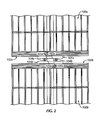
- Figure 2 is a top view of a vibratory separator screen attachment according to one embodiment of the present disclosure.
- Figure 3 is a perspective view of a screen attachment according to one embodiment of the present disclosure.
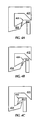
- Figures 4a-4c show an operational sequence of connecting screens according to one embodiment of the present disclosure.
- Figure 5A is a perspective view of a vibratory separator screen according to one embodiment of the present disclosure.
- Figure 5B is a close perspective view of Section B of Figure 5A according to one embodiment of the present disclosure.
- embodiments disclosed herein relate to screens used on vibratory separators. In other aspects, embodiments disclosed herein relate to vibratory separator screen attachments. In still other aspects, embodiments disclosed herein relate to apparatuses and methods used to attach multiple screens for use with oilfield vibratory separators.
- Screens 100 include screen frames 102 and generally include filtering elements (not shown), which are disposed on screen frames 102.
- a first screen 100a and a second screen 100b are illustrated disposed adjacent one another and attached via coupling of a first screen attachment 101a with a second screen attachment 101b.
- Screen attachments 101 are disposed on screen frames 102, such that when installed in a vibratory separator (not shown), the screen attachments form a force-transmitting connection.
- separator screens 100a and 100b also include corresponding frames 102a and 102b, as well as screen attachments 1 O1 a and 101b.
- Screen attachments 101a and 101b further include a vertically disposed latches 103a and 103b and vertically disposed catches 104a and 104b.
- screen attachments 101a and 101b include bearing surfaces 105a and 105b proximate respective catches 104a and 104b.
- latches 103, catches 104, and other components of screen attachments 101 disposed vertically refers to the orientation of the individual components, not the placement of the components on screens 100. Latches 103, catches 104, and the other components disclosed herein are illustrated on the side of screens 100. However, those of ordinary skill in the art will appreciate that in other embodiments, latches 103, catches 104, and other components may be disposed in vertical orientation on a top surface, bottom surface, or partially on a top surface, bottom surface, or side of screens 102.
- vertically disposed latches 103 are inserted into vertically disposed catches 104, such that latches 103 are held in place between catches 104 and bearing surfaces 105.
- latches 103 may contact bearing surfaces 105, such that latches 103 are directed to form a proper connection with catches 104.
- screen 100a includes both latch 103a and catch 104a, which correspond to catch 104b and latch 103b of screen 100b.
- a screen 100 could be configured to include multiple latches 103, catches 104, and bearing surfaces 105.
- a screen may include only latches 103 or only catches 104 and bearing surfaces 105.
- screen attachments 101 may include varied combinations of latches 103, catches 104, and bearing surfaces 105, so as to form a connection applicable to a specific separatory operation.
- Components of screen attachments 101 may be formed from a number of materials used in forming screen attachment mechanisms known to those of ordinary skill in the art. Examples of materials that may be used include steel, polypropylene, or other plastics.
- screen attachment 101 may be formed as an integral part of frame 102. In such an embodiment, screen attachment 101 may be formed from, for example, 20% glass reinforced polypropylene. Such a composition may provide a rigid screen attachment 101 that retains a required plasticity to contact bearing surface 105 and retain in catch 104.
- components of screen attachments 101 may be coated to further enhance the connective attributes established thereby.
- components of screen attachments 101 may be coated with polytetrafluoroethylene, fluorinated ethylene-propylene, perfluoroalkoxy polymer, or other coatings that provide low friction non-reactive properties to screen attachments 101.
- Such coatings may enhance the life of screen attachment 101 and/or provide for a better connection between latches 103 and catches 104.
- Such coatings may be of particular use if screen attachments 101 are composed of metals.
- screen attachments 101 formed from polypropylene may not require additional coatings.
- screen attachments 101 may be formed as an integral part of frames 102. However, in other embodiments, screen attachments 101 may be formed separate from frames 102, and later attached thereto. For example, screen attachments 101 may be mechanically fastened or chemically bonded to frames 102 after frames 102 have been formed. As such, those of ordinary skill in the art will appreciate that frames 102 may be formed from different materials than screen attachments 101. In still other embodiments, screen attachments 101 may be formed first, and then frame 102 may be molded around screen attachment 101. In such an embodiment, frame 102 may be formed around screen attachment 101 through, for example, injection molding. Additionally, because screen attachments 101 may be formed independent from frames 102, screen attachments 101 may be selectively installed on frames 102, or may be retrofitted to existing frames 102. Furthermore, screen attachments 101 may be selectively configured to frames 102 as vibratory operations require.
- both latches 103 and catches 104 are vertically oriented with respect to frames 102. Such vertical orientation allows an operator to slide a screen 100b into a vibratory separator (not shown), such that latch 103b self aligns with catch 104a.
- Bearing surface 105a may further provide a contact portion to direct latch 103b into catch 104a, should screen 100b be inserted at an inappropriate angle.
- vertically oriented screen attachments 101 are configured to prevent the retention of solids from interfering with the screen connection. For example, as solids pass over screens 100, solid particles may pass over screen attachment 101. Screen attachments 102, disposed to connect in horizontal orientation, allow solid particles from drilling waste to block the connection of latches 103 to catches 104. However, vertically orientated components allow solid particles to pass through screen attachment 102, thereby reducing interference therefrom. Additionally, should solid particles come in contact with screen attachment components, the vertical orientation of the components combined with the motion of the vibratory separator may prevent the solid particles from becoming lodged in place.
- screen attachments 301 include a first catch 304a corresponding to a first latch 303a and a second catch 304b corresponding to a second latch 303be
- screen attachment 301a also includes a first bearing surface 305a and a second bearing surface 305b.
- bearing surfaces 305 have a specialized profile, which includes a portion A. Aspects of the specialized profile may act as secondary or tertiary bearing surfaces, such that when latches 303 are inserted therein, the latches 303 contact multiple portions of bearing surfaces 305.
- bearing surfaces 305 may be varied to incorporate an optimized design for a particular attachment mechanism.
- bearing surfaces 305 may include angled, orthogonal, linear, triangular, conical, or other geometric shapes/profiles.
- bearing surfaces 305 may include profiles formed from specialized materials. In certain embodiments, it may be beneficial to increase the wear resistance, decrease friction during engagement, improve resistance to drill fluids, or otherwise improve other characteristics of bearing surfaces 305. In such embodiments, it may be beneficial to coat or form bearing surfaces from specialized materials. Exemplary materials include polytetrafluoroethylene, or other materials that may enhance the properties of bearing surfaces 305.
- latches 303 may not continuously contact catches 304. Rather, latches 303 may only contact catches 304 when an operator removes the screens from the vibratory separator (as illustrated in Figure 3 ). Such a configuration may thereby further decrease the wear on components of screen attachments 301. However, in other embodiments, latches 303 may be in substantially continuous contact with catches 304, such that motion of the screens in a lateral direction is restricted. Such a configuration may be beneficial in imparting consistent motion to all screens in the vibratory separator. Additionally, such a configuration may help prevent solid particles from falling between the screens.
- a screen attachment 301a may be configured to include two catches 304a and 304b, while a second screen attachment 301b is configured to include two latches 303a and 303b.
- a single screen (not individually illustrated) may include a first side having multiple catches 304 and a second side having multiple latches 303.
- a screen attachment 301 of a screen (not individually illustrated) may include both a catch 304 and a latch 303, a plurality of catches 304 and latches 303, or any other combination of both catches 304 and latches 303.
- catches 304 and latches 303 may be preferable.
- a screen having a screen attachment 301 including both a catch 304 and a latch 303 on each side may be substantially interchangeable, such that a drilling operator would not have to be concerned with ordering screens having attachments of appropriate configuration.
- other configurations may also allow for interchangeability, such as screens having only catches 304 on a first side, and only latches 303 on a second side.
- a number of configurations may be achieved by adjusting the number of screen attachment components, the placement of the components, and design variables of the individual components.
- latch 403 is inserted such that a distal end 406 of latch 403 contacts catch 404 (at Figure 4a ).
- contact with both catch 404 and bearing surface 405 causes latch 403 to elastically deform.
- Such deformation may thereby allow bearing surface 405 to guide latch 403 over catch 404, thereby deflecting latch 403 into a locked orientation (at Figure 4c ).
- Such a configuration may allow latch 403 to engage an attachment component of a screen by springing into place, thereby locking two screens together.
- latches 403 that elastically deform during engagement with catch 404 may provide particularly secure connections.
- the type of latch 403 used for a specific screen attachment may thus be varied according to any number of design considerations, such as, for example, the type of solids/fluid being processed, the wear rate of the screens, the type of motion used, the number of anticipated screen changes, etc.
- an operator will insert a vertically disposed latch of a first screen into a catch of a second screen.
- the inserting includes contacting the latch of the first screen with a bearing surface of the second screen, thereby providing planar alignment of the first screen to the second screen.
- a force-transmitting connection is formed, such that the connection allows the first screen and the second screen to be moved together (i.e., to allow the screens to slide in and/or out of a vibratory separator).
- an operator may simply remove the first screen, and because the screens are held together, all of the screens may be removed simultaneously.
- Such a configuration may provide for more efficient screen changes, resulting in less downtime of the vibratory separator.
- the screens may be held together, but still removed individually from the vibratory separator.
- the second screens slides toward the removal end. The operator may disengage the two screens, remove the first screen, then subsequently remove the second screen.
- the screens may more easily be removed from the separator because the screens remain engaged until the first screen is removed from the vibratory separator.
- more than two screens may also be slid together.
- three, four, or even more screens may be engaged during operation of the vibratory separator, and then removed according to the methods detailed above.
- the operator may separate the screens by, for example, angling one of the screens to allow the latch to slide out from the catch.
- the operator may slide one of the screens in a vertical plane (e.g., up or down) such that the latch may be removed from the catch.
- the later method of disengaging the screens may be preferable in embodiments having elastically deformable latches or catches.
- the operator may slide one of the screens in a horizontal plane (e.g., side-to-side) such that the latch may be removed from the catch.
- bearing surfaces of the screen attachments may provide for the alignment of screens during insertion into the vibratory separator.
- the first screen and the second screen may be aligned within the vibratory separator.
- the operator may be able to move multiple screens in unison, such that the screens may be moved into an optimal placement.
- FIG. 1 may depict screens having a screen attachment on a first side of the screen and no screen attachment on a second side of the screen.
- Such a configuration may be used as a back screen or a front screen (i.e., the screen first inserted or last inserted into a vibratory separator).
- Such back or front screens may further include a softer sealing material on the side of the screen not having a screen attachment to seal the screen against a side of the separator.
- screen attachments such as disclosed herein, may be included on one side, two sides, three sides, or all sides of the vibratory separator screen.
- screen attachments may further include a seal.
- the seal may be placed on a top side of the screen, spatially oriented above the catches and/or latches.
- the seal may prevent the drilling fluids and solid particles from contacting the screen attachment components, thereby extending the life of the components.
- a seal may further enhance the efficiency of the separatory operation by preventing drilling fluids and solid particles from passing between the screens (i.e., bypassing the screens without being filtered).
- exemplary seals may be formed from rubbers, plastics, thermoplastic elastomers ("TPE”), foams, polychloroprene, polypropylene, nylon, mylar, composites, and/or any combinations thereof.
- TPE thermoplastic elastomers
- sealing elements may extend to cover substantially all of or just a portion of the attachment components.
- at least one seal of opposing screens may interface to cover substantially all of opposing screen attachment components.
- screen 500 includes a plurality of screen attachments 501.
- Screen attachments 501 include a latch 503, a catch 504, and a bearing surface 505.
- bearing surface 505 is recessed into the screen frame. By recessing bearing surface 505 into the screen frame, as solid particles pass over the screen 500 during use, the likelihood of solid particles becoming trapped between components of screen attachment 501 may be decreased.
- a seal (not illustrated) may be affixed to the screen frame, as described above.
- screen 500 only includes screen attachments 501 one side of the screen frame. Such an embodiment may be used as a screen that is inserted into a vibratory separator as either the first screen or last screen. Because one side of the vibratory separator does not include screen attachments 501, the side without screen attachments 501 may better seal against an end of the vibratory separator. In other embodiments, screen 500 may be designed to include screen attachments 501 on two or more sides of screen 500. In such embodiments, the vibratory separator may include attachment components that correspond to screen attachments 501, thereby further securing screen 500 in place during operation.
- embodiments of the present disclosure may provide for screens for vibratory separators that allow for more efficient screen changes. Because the screen attachments of the present disclosure may allow an operator to remove multiple screens from a separator at the same time, the operator may be able to complete a screen change in less time. By decreasing the time required for screen changes, the downtime of a vibratory shaker may also be decreased, thereby allowing a greater of volume of drilling waste to be processed.
- embodiments of the present disclosure may provide for a screen attachment mechanism that is less likely to fail during operation.
- horizontally opposed screen attachments would be disengaged due to lodged solid particles between the individual attachment components. Because the latches and catches of the present screen attachments are vertically oriented, drilling waste that falls between screens may not get lodged between the individual screen attachment components, thereby retaining screen engagement.
- screens designed in accordance with the embodiments disclosed herein may include self-aligning features, further enhancing the separating efficiency of the vibratory operation. Because bearing surfaces of the present disclosure may provide for attachments that are locked together at an optimal orientation, less drilling waste may bypass the screens, thereby increasing the efficiency of the separatory process.
- embodiments of the present disclosure may incorporate screen attachment components that are configured such that a screen may be installed in a vibratory separator with either side of the screen being inserted first. As such, screens may be placed into a vibratory separator without regard to which end is being inserted first. Such design considerations may further expedite screen changes, thereby further increasing the efficiency of the vibratory operation.
Landscapes
- Combined Means For Separation Of Solids (AREA)
Claims (16)
- Sieb (100a, 500) für eine Vibrationstrenneinrichtung, wobei das Sieb umfasst:einen Siebrahmen (102); undeine Siebbefestigung (101a, 301a, 501), wobei die Siebbefestigung (101a, 301a, 501) umfasst:mindestens einen vertikal angeordneten Sperrhaken (103a, 303a, 403, 503) an dem Siebrahmen (102);mindestens einen vertikal angeordneten Greifhaken (104a, 304a, 404, 504) an dem Siebrahmen (102); undmindestens eine Führungsfläche (105a, 305a, 405, 505) in der Nähe des mindestens einen vertikal angeordneten Greifhakens (104a, 304a, 404, 504) und die dafür konfiguriert ist, den mindestens einen vertikal angeordneten Sperrhaken (103a, 303a, 403, 503) in den mindestens einen vertikalangeordneten Greifhaken (104a, 304a, 404, 504) einzuführen;dadurch gekennzeichnet, dass der mindestens eine vertikal angeordnete Sperrhaken (103a, 303a, 403, 503) elastisch verformbar ist.
- Sieb (100a, 500) nach Anspruch 1, das ferner umfasst:ein Filterelement, das an dem Siebrahmen (102) angeordnet ist.
- Sieb (100a, 500) nach Anspruch 1, das ferner umfasst:eine Siebdichtung, die über der Siebbefestigung (101a, 301a, 501) angeordnet ist.
- Sieb (100a, 500) nach Anspruch 1, das ferner umfasst:eine zweite Siebbefestigung (101b, 301b), die an einem Rahmenende, das der ersten Siebbefestigung (101a, 301a, 501) gegenüberliegt, angeordnet ist, wobei die zweite Siebbefestigung (101b, 301b) umfasst:mindestens einen vertikal angeordneten Sperrhaken (103b, 303b) an dem Siebrahmen (102);mindestens einen vertikal angeordneten Greifhaken (104b, 304b) an dem Siebrahmen (102); undmindestens eine Führungsfläche (105b, 305b) in der Nähe des mindestens einen vertikal angeordneten Greifhakens (104b, 304b) und die dafür konfiguriert ist, den mindestens einen vertikal angeordneten Sperrhaken (103a, 303a, 403, 503) in den mindestens einen vertikal angeordneten Greifhaken (104a, 304a, 404, 504) einzuführen.
- Siebbefestigung (101a, 301a, 501) nach Anspruch 1, bei der die Führungsfläche (105a, 305a, 405, 505) eine im Wesentlichen dreieckige Geometrie umfasst.
- Siebbefestigung (101a, 301a, 501) nach Anspruch 1, bei der die Führungsfläche (105a, 305a, 405, 505) eine im Wesentlichen unregelmäßige Geometrie umfasst.
- Siebbefestigung (101a, 301a, 501) nach Anspruch 1, bei der die Führungsfläche (105a, 305a, 405, 505) so konfiguriert ist, dass sie ein Selbstjustierungsmerkmal bereitstellt.
- Siebbefestigung (101a, 301a, 501) nach Anspruch 1, bei der der Greifhaken (104a, 304a, 404, 504) dafür konfiguriert ist, einen vertikal angeordneten Sperrhaken eines zweiten Siebs (100b) aufzunehmen.
- Verfahren zum Anordnen von Vibrationstrenneinrichtungs-Sieben (100, 500), wobei das Verfahren umfasst:Platzieren eines ersten Siebs (100a) mit einem ersten vertikal angeordneten Sperrhaken (103a, 303a) in einer Vibrationstrenneinrichtung;Platzieren eines zweiten Siebs (100b) mit einem vertikal angeordneten Greifhaken (104a, 304a) in der Vibrationstrenneinrichtung; undAusbilden einer Kraftübertragungsverbindung, wobei das Ausbilden umfasst:in Eingriff Bringen des ersten vertikal angeordneten Sperrhakens (103a, 3 03 a) mit dem ersten vertikal angeordneten Greifhaken (104a, 304a);dadurch gekennzeichnet, dass das Ausbilden ferner das elastische Verformen des ersten vertikal angeordneten Sperrhakens (103a, 303a) umfasst.
- Verfahren nach Anspruch 9, das ferner umfasst:Ausbilden einer planaren Ausrichtung des ersten Siebs (100a) auf ein zweites Sieb (100b); undAbdichten mindestens einer oberen Oberfläche des ersten und des zweiten Siebs (100a, 100b) an einer Grenzfläche von Rahmen (102a, 102b) des ersten und des zweiten Siebs (100a, 100b).
- Verfahren nach Anspruch 9, das ferner umfasst:Ausrichten des ersten Siebs (100a) auf das zweite Sieb (100b) durch Bewegen des ersten angeordneten Sperrhakens (103a, 303a) gegen eine Führungsfläche (105) des zweiten Siebs (100b).
- Verfahren nach Anspruch 11, bei dem das in Eingriff Bringen umfasst:Schieben des zweiten Siebs (100b) in planare Ausrichtung auf das erste Sieb (100a).
- Verfahren nach Anspruch 12, das ferner umfasst:Bewegen des ersten Siebs (100a) und des zweiten Siebs (100b) in funktionsfähige Anordnung in der Vibrationstrenneinrichtung.
- Verfahren nach Anspruch 12, das ferner umfasst:Entfernen des ersten Siebs (100a) von der Vibrationstrenneinrichtung, wobei die Bewegung des ersten Siebs (100a) eine Bewegung des zweiten Siebs (100b) veranlasst.
- Verfahren nach Anspruch 14, wobei das Verfahren ferner umfasst:Lösen des ersten Siebs von dem zweiten Sieb, wobei das Lösen das Schwenken des ersten Siebs (100a) um einen Winkel relativ zu dem zweiten Sieb (100b) umfasst,wobei der erste vertikal angeordnete Sperrhaken (103a, 303a) den ersten vertikal angeordneten Greifhaken (104a, 304a) löst.
- Verfahren nach Anspruch 9, bei dem das erste Sieb (100a) einen zweiten vertikal angeordneten Greifhaken (104b, 304b) aufweist und das zweite Sieb (100b) einen zweiten vertikal angeordneten Sperrhaken (103b, 303b) aufweist.
Applications Claiming Priority (2)
| Application Number | Priority Date | Filing Date | Title |
|---|---|---|---|
| US97789107P | 2007-10-05 | 2007-10-05 | |
| PCT/US2008/078301 WO2009046018A1 (en) | 2007-10-05 | 2008-09-30 | Vibratory separator screen attachment |
Publications (2)
| Publication Number | Publication Date |
|---|---|
| EP2219794A1 EP2219794A1 (de) | 2010-08-25 |
| EP2219794B1 true EP2219794B1 (de) | 2011-12-21 |
Family
ID=40349949
Family Applications (1)
| Application Number | Title | Priority Date | Filing Date |
|---|---|---|---|
| EP08836086A Active EP2219794B1 (de) | 2007-10-05 | 2008-09-30 | Vibrationstrennvorrichtungssiebbefestigung |
Country Status (11)
| Country | Link |
|---|---|
| US (1) | US8517179B2 (de) |
| EP (1) | EP2219794B1 (de) |
| CN (1) | CN101821022B (de) |
| AR (1) | AR068663A1 (de) |
| AT (1) | ATE537913T1 (de) |
| BR (1) | BRPI0817523B1 (de) |
| CA (1) | CA2701729C (de) |
| DK (1) | DK2219794T3 (de) |
| EA (1) | EA016069B1 (de) |
| MX (1) | MX2010003666A (de) |
| WO (1) | WO2009046018A1 (de) |
Cited By (1)
| Publication number | Priority date | Publication date | Assignee | Title |
|---|---|---|---|---|
| US12042822B2 (en) | 2012-05-25 | 2024-07-23 | Derrick Corporation | Injection molded screening apparatuses and methods |
Families Citing this family (14)
| Publication number | Priority date | Publication date | Assignee | Title |
|---|---|---|---|---|
| CA2701729C (en) * | 2007-10-05 | 2013-11-26 | M-I Llc | Vibratory separator screen attachment |
| GB2461726A (en) * | 2008-07-10 | 2010-01-13 | United Wire Ltd | Sifting Screen |
| CN109013296B (zh) * | 2012-05-25 | 2022-10-28 | 德里克公司 | 注塑成型的筛设备与方法 |
| US9409209B2 (en) | 2012-05-25 | 2016-08-09 | Derrick Corporation | Injection molded screening apparatuses and methods |
| US10576502B2 (en) | 2012-05-25 | 2020-03-03 | Derrick Corporation | Injection molded screening apparatuses and methods |
| WO2016077448A1 (en) * | 2014-11-12 | 2016-05-19 | M-I Drilling Fluids U.K. Ltd. | Apparatus, system and method for connecting filtration screens |
| US10065213B2 (en) * | 2015-05-21 | 2018-09-04 | M-I Drilling Fluids Uk Ltd | Vibratory separator screen adapter |
| CA2950365C (en) * | 2015-08-14 | 2018-06-12 | Syncrude Canada Ltd. | Slurry screen cloth |
| MX2019012763A (es) | 2017-04-28 | 2019-12-16 | Derrick Corp | Composiciones termoplasticas, metodos, aparato y usos. |
| US11505638B2 (en) | 2017-04-28 | 2022-11-22 | Derrick Corporation | Thermoplastic compositions, methods, apparatus, and uses |
| EP4163020A1 (de) | 2017-06-06 | 2023-04-12 | Derrick Corporation | Siebverfahren und siebvorrichtungen |
| US11213857B2 (en) | 2017-06-06 | 2022-01-04 | Derrick Corporation | Method and apparatus for screening |
| EP3581282A1 (de) * | 2018-06-14 | 2019-12-18 | Metso Minerals, Inc. | Screening-vorrichtung |
| WO2021127344A1 (en) * | 2019-12-20 | 2021-06-24 | Schlumberger Technology Corporation | Filter screens with curved feed and discharge surfaces |
Family Cites Families (12)
| Publication number | Priority date | Publication date | Assignee | Title |
|---|---|---|---|---|
| CH358573A (it) | 1958-04-21 | 1961-11-30 | Proserpi Ivan | Insieme di profilati accoppiabili tra di loro per costituire delle pareti |
| CH385461A (de) | 1960-04-11 | 1964-12-15 | Schweizer Werner | Satz von ineinander klemmbaren Profilschienen zur Verbindung von Bauteilen, z.B. Platten |
| NL138604C (de) | 1968-09-25 | |||
| US5227916A (en) * | 1992-05-13 | 1993-07-13 | Minnesota Mining And Manufacturing Company | Adjustable mounting mechanism for an optical filter screen |
| US6443310B1 (en) | 1993-04-30 | 2002-09-03 | Varco I/P, Inc. | Seal screen structure |
| ATE279268T1 (de) * | 1997-03-01 | 2004-10-15 | United Wire Ltd | Vorrichtung zum reparieren oder renovieren eines filtersiebes |
| GB0120862D0 (en) * | 2001-08-29 | 2001-10-17 | United Wire Ltd | Method and device for joining screens |
| US7063214B2 (en) * | 2003-02-04 | 2006-06-20 | Varco I/P, Inc. | Interlocking screens for vibratory separators |
| RU2007114078A (ru) * | 2004-09-15 | 2008-10-27 | Метсо Минералз (Веар Протекшн) Аб (Se) | Сито и элемент сита |
| US7731035B2 (en) * | 2005-02-07 | 2010-06-08 | Screenex Australia Pty Ltd | Ore screening panel frame system |
| CN2805955Y (zh) * | 2005-07-20 | 2006-08-16 | 崔艳 | 一种新型耐磨细筛筛片 |
| CA2701729C (en) * | 2007-10-05 | 2013-11-26 | M-I Llc | Vibratory separator screen attachment |
-
2008
- 2008-09-30 CA CA2701729A patent/CA2701729C/en active Active
- 2008-09-30 WO PCT/US2008/078301 patent/WO2009046018A1/en active Application Filing
- 2008-09-30 US US12/681,048 patent/US8517179B2/en active Active
- 2008-09-30 DK DK08836086.2T patent/DK2219794T3/da active
- 2008-09-30 MX MX2010003666A patent/MX2010003666A/es active IP Right Grant
- 2008-09-30 CN CN200880110325.8A patent/CN101821022B/zh active Active
- 2008-09-30 EP EP08836086A patent/EP2219794B1/de active Active
- 2008-09-30 BR BRPI0817523-3A patent/BRPI0817523B1/pt active Search and Examination
- 2008-09-30 EA EA201070432A patent/EA016069B1/ru not_active IP Right Cessation
- 2008-09-30 AT AT08836086T patent/ATE537913T1/de active
- 2008-10-03 AR ARP080104339A patent/AR068663A1/es active IP Right Grant
Cited By (1)
| Publication number | Priority date | Publication date | Assignee | Title |
|---|---|---|---|---|
| US12042822B2 (en) | 2012-05-25 | 2024-07-23 | Derrick Corporation | Injection molded screening apparatuses and methods |
Also Published As
| Publication number | Publication date |
|---|---|
| CA2701729C (en) | 2013-11-26 |
| EA201070432A1 (ru) | 2010-10-29 |
| US8517179B2 (en) | 2013-08-27 |
| US20100270215A1 (en) | 2010-10-28 |
| BRPI0817523B1 (pt) | 2019-09-24 |
| EA016069B1 (ru) | 2012-01-30 |
| CN101821022B (zh) | 2015-05-06 |
| EP2219794A1 (de) | 2010-08-25 |
| AR068663A1 (es) | 2009-11-25 |
| WO2009046018A1 (en) | 2009-04-09 |
| CN101821022A (zh) | 2010-09-01 |
| MX2010003666A (es) | 2010-06-02 |
| DK2219794T3 (da) | 2012-04-16 |
| ATE537913T1 (de) | 2012-01-15 |
| CA2701729A1 (en) | 2009-04-09 |
| BRPI0817523A2 (pt) | 2017-05-02 |
Similar Documents
| Publication | Publication Date | Title |
|---|---|---|
| EP2219794B1 (de) | Vibrationstrennvorrichtungssiebbefestigung | |
| US8561804B2 (en) | Screen clamp | |
| US8231009B2 (en) | Magnetic screen clamping | |
| US7753213B2 (en) | Composite screen | |
| USRE45746E1 (en) | Peripheral sealing system for pre-tensioned screens | |
| US8956543B2 (en) | Feeder with screen for shaker | |
| WO2009048783A2 (en) | Fluid distribution for a shaker | |
| US9957762B2 (en) | Fluid distribution system | |
| US20140166307A1 (en) | Self clamping shaker screens | |
| US9687878B2 (en) | Locating feature for screen | |
| WO2023196019A1 (en) | Shaker screen retention rail and channel system | |
| WO2013116716A1 (en) | Multi-deck vibratory separator with series and parallel fluid processing capabilities |
Legal Events
| Date | Code | Title | Description |
|---|---|---|---|
| PUAI | Public reference made under article 153(3) epc to a published international application that has entered the european phase |
Free format text: ORIGINAL CODE: 0009012 |
|
| 17P | Request for examination filed |
Effective date: 20100503 |
|
| AK | Designated contracting states |
Kind code of ref document: A1 Designated state(s): AT BE BG CH CY CZ DE DK EE ES FI FR GB GR HR HU IE IS IT LI LT LU LV MC MT NL NO PL PT RO SE SI SK TR |
|
| AX | Request for extension of the european patent |
Extension state: AL BA MK RS |
|
| 17Q | First examination report despatched |
Effective date: 20101115 |
|
| DAX | Request for extension of the european patent (deleted) | ||
| GRAP | Despatch of communication of intention to grant a patent |
Free format text: ORIGINAL CODE: EPIDOSNIGR1 |
|
| GRAS | Grant fee paid |
Free format text: ORIGINAL CODE: EPIDOSNIGR3 |
|
| GRAA | (expected) grant |
Free format text: ORIGINAL CODE: 0009210 |
|
| AK | Designated contracting states |
Kind code of ref document: B1 Designated state(s): AT BE BG CH CY CZ DE DK EE ES FI FR GB GR HR HU IE IS IT LI LT LU LV MC MT NL NO PL PT RO SE SI SK TR |
|
| REG | Reference to a national code |
Ref country code: GB Ref legal event code: FG4D |
|
| REG | Reference to a national code |
Ref country code: CH Ref legal event code: EP |
|
| REG | Reference to a national code |
Ref country code: AT Ref legal event code: REF Ref document number: 537913 Country of ref document: AT Kind code of ref document: T Effective date: 20120115 |
|
| REG | Reference to a national code |
Ref country code: IE Ref legal event code: FG4D |
|
| REG | Reference to a national code |
Ref country code: DE Ref legal event code: R096 Ref document number: 602008012243 Country of ref document: DE Effective date: 20120308 |
|
| REG | Reference to a national code |
Ref country code: NL Ref legal event code: T3 |
|
| REG | Reference to a national code |
Ref country code: DK Ref legal event code: T3 |
|
| PG25 | Lapsed in a contracting state [announced via postgrant information from national office to epo] |
Ref country code: LT Free format text: LAPSE BECAUSE OF FAILURE TO SUBMIT A TRANSLATION OF THE DESCRIPTION OR TO PAY THE FEE WITHIN THE PRESCRIBED TIME-LIMIT Effective date: 20111221 |
|
| REG | Reference to a national code |
Ref country code: NO Ref legal event code: T2 Effective date: 20111221 |
|
| LTIE | Lt: invalidation of european patent or patent extension |
Effective date: 20111221 |
|
| PG25 | Lapsed in a contracting state [announced via postgrant information from national office to epo] |
Ref country code: GR Free format text: LAPSE BECAUSE OF FAILURE TO SUBMIT A TRANSLATION OF THE DESCRIPTION OR TO PAY THE FEE WITHIN THE PRESCRIBED TIME-LIMIT Effective date: 20120322 Ref country code: HR Free format text: LAPSE BECAUSE OF FAILURE TO SUBMIT A TRANSLATION OF THE DESCRIPTION OR TO PAY THE FEE WITHIN THE PRESCRIBED TIME-LIMIT Effective date: 20111221 Ref country code: LV Free format text: LAPSE BECAUSE OF FAILURE TO SUBMIT A TRANSLATION OF THE DESCRIPTION OR TO PAY THE FEE WITHIN THE PRESCRIBED TIME-LIMIT Effective date: 20111221 Ref country code: SE Free format text: LAPSE BECAUSE OF FAILURE TO SUBMIT A TRANSLATION OF THE DESCRIPTION OR TO PAY THE FEE WITHIN THE PRESCRIBED TIME-LIMIT Effective date: 20111221 Ref country code: SI Free format text: LAPSE BECAUSE OF FAILURE TO SUBMIT A TRANSLATION OF THE DESCRIPTION OR TO PAY THE FEE WITHIN THE PRESCRIBED TIME-LIMIT Effective date: 20111221 |
|
| PG25 | Lapsed in a contracting state [announced via postgrant information from national office to epo] |
Ref country code: CY Free format text: LAPSE BECAUSE OF FAILURE TO SUBMIT A TRANSLATION OF THE DESCRIPTION OR TO PAY THE FEE WITHIN THE PRESCRIBED TIME-LIMIT Effective date: 20111221 Ref country code: BE Free format text: LAPSE BECAUSE OF FAILURE TO SUBMIT A TRANSLATION OF THE DESCRIPTION OR TO PAY THE FEE WITHIN THE PRESCRIBED TIME-LIMIT Effective date: 20111221 |
|
| PG25 | Lapsed in a contracting state [announced via postgrant information from national office to epo] |
Ref country code: IS Free format text: LAPSE BECAUSE OF FAILURE TO SUBMIT A TRANSLATION OF THE DESCRIPTION OR TO PAY THE FEE WITHIN THE PRESCRIBED TIME-LIMIT Effective date: 20120421 Ref country code: SK Free format text: LAPSE BECAUSE OF FAILURE TO SUBMIT A TRANSLATION OF THE DESCRIPTION OR TO PAY THE FEE WITHIN THE PRESCRIBED TIME-LIMIT Effective date: 20111221 Ref country code: CZ Free format text: LAPSE BECAUSE OF FAILURE TO SUBMIT A TRANSLATION OF THE DESCRIPTION OR TO PAY THE FEE WITHIN THE PRESCRIBED TIME-LIMIT Effective date: 20111221 Ref country code: BG Free format text: LAPSE BECAUSE OF FAILURE TO SUBMIT A TRANSLATION OF THE DESCRIPTION OR TO PAY THE FEE WITHIN THE PRESCRIBED TIME-LIMIT Effective date: 20120321 Ref country code: EE Free format text: LAPSE BECAUSE OF FAILURE TO SUBMIT A TRANSLATION OF THE DESCRIPTION OR TO PAY THE FEE WITHIN THE PRESCRIBED TIME-LIMIT Effective date: 20111221 |
|
| PG25 | Lapsed in a contracting state [announced via postgrant information from national office to epo] |
Ref country code: PL Free format text: LAPSE BECAUSE OF FAILURE TO SUBMIT A TRANSLATION OF THE DESCRIPTION OR TO PAY THE FEE WITHIN THE PRESCRIBED TIME-LIMIT Effective date: 20111221 Ref country code: RO Free format text: LAPSE BECAUSE OF FAILURE TO SUBMIT A TRANSLATION OF THE DESCRIPTION OR TO PAY THE FEE WITHIN THE PRESCRIBED TIME-LIMIT Effective date: 20111221 Ref country code: PT Free format text: LAPSE BECAUSE OF FAILURE TO SUBMIT A TRANSLATION OF THE DESCRIPTION OR TO PAY THE FEE WITHIN THE PRESCRIBED TIME-LIMIT Effective date: 20120423 |
|
| REG | Reference to a national code |
Ref country code: AT Ref legal event code: MK05 Ref document number: 537913 Country of ref document: AT Kind code of ref document: T Effective date: 20111221 |
|
| PLBE | No opposition filed within time limit |
Free format text: ORIGINAL CODE: 0009261 |
|
| STAA | Information on the status of an ep patent application or granted ep patent |
Free format text: STATUS: NO OPPOSITION FILED WITHIN TIME LIMIT |
|
| 26N | No opposition filed |
Effective date: 20120924 |
|
| REG | Reference to a national code |
Ref country code: DE Ref legal event code: R097 Ref document number: 602008012243 Country of ref document: DE Effective date: 20120924 |
|
| PG25 | Lapsed in a contracting state [announced via postgrant information from national office to epo] |
Ref country code: AT Free format text: LAPSE BECAUSE OF FAILURE TO SUBMIT A TRANSLATION OF THE DESCRIPTION OR TO PAY THE FEE WITHIN THE PRESCRIBED TIME-LIMIT Effective date: 20111221 |
|
| PG25 | Lapsed in a contracting state [announced via postgrant information from national office to epo] |
Ref country code: ES Free format text: LAPSE BECAUSE OF FAILURE TO SUBMIT A TRANSLATION OF THE DESCRIPTION OR TO PAY THE FEE WITHIN THE PRESCRIBED TIME-LIMIT Effective date: 20120401 Ref country code: MC Free format text: LAPSE BECAUSE OF NON-PAYMENT OF DUE FEES Effective date: 20120930 |
|
| REG | Reference to a national code |
Ref country code: CH Ref legal event code: PL |
|
| PG25 | Lapsed in a contracting state [announced via postgrant information from national office to epo] |
Ref country code: FI Free format text: LAPSE BECAUSE OF FAILURE TO SUBMIT A TRANSLATION OF THE DESCRIPTION OR TO PAY THE FEE WITHIN THE PRESCRIBED TIME-LIMIT Effective date: 20111221 |
|
| REG | Reference to a national code |
Ref country code: FR Ref legal event code: ST Effective date: 20130531 |
|
| REG | Reference to a national code |
Ref country code: IE Ref legal event code: MM4A |
|
| PG25 | Lapsed in a contracting state [announced via postgrant information from national office to epo] |
Ref country code: IE Free format text: LAPSE BECAUSE OF NON-PAYMENT OF DUE FEES Effective date: 20120930 Ref country code: LI Free format text: LAPSE BECAUSE OF NON-PAYMENT OF DUE FEES Effective date: 20120930 Ref country code: CH Free format text: LAPSE BECAUSE OF NON-PAYMENT OF DUE FEES Effective date: 20120930 |
|
| PG25 | Lapsed in a contracting state [announced via postgrant information from national office to epo] |
Ref country code: FR Free format text: LAPSE BECAUSE OF NON-PAYMENT OF DUE FEES Effective date: 20121001 |
|
| PG25 | Lapsed in a contracting state [announced via postgrant information from national office to epo] |
Ref country code: MT Free format text: LAPSE BECAUSE OF FAILURE TO SUBMIT A TRANSLATION OF THE DESCRIPTION OR TO PAY THE FEE WITHIN THE PRESCRIBED TIME-LIMIT Effective date: 20111221 |
|
| PG25 | Lapsed in a contracting state [announced via postgrant information from national office to epo] |
Ref country code: TR Free format text: LAPSE BECAUSE OF FAILURE TO SUBMIT A TRANSLATION OF THE DESCRIPTION OR TO PAY THE FEE WITHIN THE PRESCRIBED TIME-LIMIT Effective date: 20111221 |
|
| PG25 | Lapsed in a contracting state [announced via postgrant information from national office to epo] |
Ref country code: LU Free format text: LAPSE BECAUSE OF NON-PAYMENT OF DUE FEES Effective date: 20120930 |
|
| PG25 | Lapsed in a contracting state [announced via postgrant information from national office to epo] |
Ref country code: HU Free format text: LAPSE BECAUSE OF FAILURE TO SUBMIT A TRANSLATION OF THE DESCRIPTION OR TO PAY THE FEE WITHIN THE PRESCRIBED TIME-LIMIT Effective date: 20080930 |
|
| PGFP | Annual fee paid to national office [announced via postgrant information from national office to epo] |
Ref country code: EE Payment date: 20170926 Year of fee payment: 13 |
|
| PGFP | Annual fee paid to national office [announced via postgrant information from national office to epo] |
Ref country code: DK Payment date: 20170922 Year of fee payment: 10 |
|
| PGFP | Annual fee paid to national office [announced via postgrant information from national office to epo] |
Ref country code: DE Payment date: 20171130 Year of fee payment: 10 |
|
| REG | Reference to a national code |
Ref country code: DE Ref legal event code: R119 Ref document number: 602008012243 Country of ref document: DE |
|
| REG | Reference to a national code |
Ref country code: DK Ref legal event code: EBP Effective date: 20180930 |
|
| PG25 | Lapsed in a contracting state [announced via postgrant information from national office to epo] |
Ref country code: DE Free format text: LAPSE BECAUSE OF NON-PAYMENT OF DUE FEES Effective date: 20190402 Ref country code: IT Free format text: LAPSE BECAUSE OF NON-PAYMENT OF DUE FEES Effective date: 20180930 |
|
| PG25 | Lapsed in a contracting state [announced via postgrant information from national office to epo] |
Ref country code: DK Free format text: LAPSE BECAUSE OF NON-PAYMENT OF DUE FEES Effective date: 20180930 |
|
| PGFP | Annual fee paid to national office [announced via postgrant information from national office to epo] |
Ref country code: NL Payment date: 20230816 Year of fee payment: 16 |
|
| PGFP | Annual fee paid to national office [announced via postgrant information from national office to epo] |
Ref country code: NO Payment date: 20230911 Year of fee payment: 16 Ref country code: GB Payment date: 20230810 Year of fee payment: 16 |