EP2219254A1 - Cell for fuel battery, method for producing the same, and gas channel structure for fuel battery - Google Patents
Cell for fuel battery, method for producing the same, and gas channel structure for fuel battery Download PDFInfo
- Publication number
- EP2219254A1 EP2219254A1 EP08847650A EP08847650A EP2219254A1 EP 2219254 A1 EP2219254 A1 EP 2219254A1 EP 08847650 A EP08847650 A EP 08847650A EP 08847650 A EP08847650 A EP 08847650A EP 2219254 A1 EP2219254 A1 EP 2219254A1
- Authority
- EP
- European Patent Office
- Prior art keywords
- gas channel
- electrode assembly
- membrane electrode
- cell
- channel substrate
- Prior art date
- Legal status (The legal status is an assumption and is not a legal conclusion. Google has not performed a legal analysis and makes no representation as to the accuracy of the status listed.)
- Granted
Links
- 239000000446 fuel Substances 0.000 title claims abstract description 92
- 238000004519 manufacturing process Methods 0.000 title claims description 23
- 239000007789 gas Substances 0.000 claims abstract description 177
- 239000000758 substrate Substances 0.000 claims abstract description 86
- 239000012528 membrane Substances 0.000 claims abstract description 61
- 238000000465 moulding Methods 0.000 claims abstract description 61
- 239000004020 conductor Substances 0.000 claims abstract description 28
- 239000007769 metal material Substances 0.000 claims abstract description 23
- 239000000463 material Substances 0.000 claims abstract description 22
- 230000015572 biosynthetic process Effects 0.000 claims description 18
- 239000010931 gold Substances 0.000 abstract description 87
- PCHJSUWPFVWCPO-UHFFFAOYSA-N gold Chemical compound [Au] PCHJSUWPFVWCPO-UHFFFAOYSA-N 0.000 abstract description 47
- 229910052737 gold Inorganic materials 0.000 abstract description 47
- RTAQQCXQSZGOHL-UHFFFAOYSA-N Titanium Chemical compound [Ti] RTAQQCXQSZGOHL-UHFFFAOYSA-N 0.000 abstract description 16
- 239000010936 titanium Substances 0.000 abstract description 16
- 229910052719 titanium Inorganic materials 0.000 abstract description 15
- 239000010935 stainless steel Substances 0.000 abstract description 13
- 229910001220 stainless steel Inorganic materials 0.000 abstract description 13
- GWEVSGVZZGPLCZ-UHFFFAOYSA-N Titan oxide Chemical compound O=[Ti]=O GWEVSGVZZGPLCZ-UHFFFAOYSA-N 0.000 abstract description 11
- OGIDPMRJRNCKJF-UHFFFAOYSA-N titanium oxide Inorganic materials [Ti]=O OGIDPMRJRNCKJF-UHFFFAOYSA-N 0.000 abstract description 7
- 238000007747 plating Methods 0.000 description 37
- 229910052751 metal Inorganic materials 0.000 description 32
- 239000002184 metal Substances 0.000 description 32
- 230000000052 comparative effect Effects 0.000 description 25
- 238000000034 method Methods 0.000 description 24
- 238000010586 diagram Methods 0.000 description 16
- 239000003054 catalyst Substances 0.000 description 15
- 238000009792 diffusion process Methods 0.000 description 15
- 238000010248 power generation Methods 0.000 description 15
- BASFCYQUMIYNBI-UHFFFAOYSA-N platinum Chemical group [Pt] BASFCYQUMIYNBI-UHFFFAOYSA-N 0.000 description 11
- KRHYYFGTRYWZRS-UHFFFAOYSA-N Fluorane Chemical compound F KRHYYFGTRYWZRS-UHFFFAOYSA-N 0.000 description 10
- 238000000576 coating method Methods 0.000 description 10
- QAOWNCQODCNURD-UHFFFAOYSA-N Sulfuric acid Chemical compound OS(O)(=O)=O QAOWNCQODCNURD-UHFFFAOYSA-N 0.000 description 8
- 239000011248 coating agent Substances 0.000 description 8
- XLYOFNOQVPJJNP-UHFFFAOYSA-N water Substances O XLYOFNOQVPJJNP-UHFFFAOYSA-N 0.000 description 8
- 229910001868 water Inorganic materials 0.000 description 8
- 238000007598 dipping method Methods 0.000 description 7
- 239000003792 electrolyte Substances 0.000 description 7
- 230000001590 oxidative effect Effects 0.000 description 7
- 239000002253 acid Substances 0.000 description 6
- 239000003513 alkali Substances 0.000 description 6
- 238000009713 electroplating Methods 0.000 description 6
- 239000002737 fuel gas Substances 0.000 description 6
- 239000000126 substance Substances 0.000 description 6
- 238000005406 washing Methods 0.000 description 6
- 238000004140 cleaning Methods 0.000 description 5
- 238000005260 corrosion Methods 0.000 description 5
- 230000007797 corrosion Effects 0.000 description 5
- 239000001257 hydrogen Substances 0.000 description 5
- 229910052739 hydrogen Inorganic materials 0.000 description 5
- 230000003472 neutralizing effect Effects 0.000 description 5
- 239000007800 oxidant agent Substances 0.000 description 5
- 238000006722 reduction reaction Methods 0.000 description 5
- UFHFLCQGNIYNRP-UHFFFAOYSA-N Hydrogen Chemical compound [H][H] UFHFLCQGNIYNRP-UHFFFAOYSA-N 0.000 description 4
- QVGXLLKOCUKJST-UHFFFAOYSA-N atomic oxygen Chemical compound [O] QVGXLLKOCUKJST-UHFFFAOYSA-N 0.000 description 4
- 239000010949 copper Substances 0.000 description 4
- 238000005238 degreasing Methods 0.000 description 4
- 238000010030 laminating Methods 0.000 description 4
- 239000007788 liquid Substances 0.000 description 4
- 239000001301 oxygen Substances 0.000 description 4
- 229910052760 oxygen Inorganic materials 0.000 description 4
- 239000002245 particle Substances 0.000 description 4
- 238000005240 physical vapour deposition Methods 0.000 description 4
- 229910052697 platinum Inorganic materials 0.000 description 4
- 229920000642 polymer Polymers 0.000 description 4
- 239000007787 solid Substances 0.000 description 4
- KDLHZDBZIXYQEI-UHFFFAOYSA-N Palladium Chemical compound [Pd] KDLHZDBZIXYQEI-UHFFFAOYSA-N 0.000 description 3
- 238000010438 heat treatment Methods 0.000 description 3
- 238000002161 passivation Methods 0.000 description 3
- 230000009467 reduction Effects 0.000 description 3
- 238000004544 sputter deposition Methods 0.000 description 3
- 229920000049 Carbon (fiber) Polymers 0.000 description 2
- RYGMFSIKBFXOCR-UHFFFAOYSA-N Copper Chemical compound [Cu] RYGMFSIKBFXOCR-UHFFFAOYSA-N 0.000 description 2
- VEXZGXHMUGYJMC-UHFFFAOYSA-N Hydrochloric acid Chemical compound Cl VEXZGXHMUGYJMC-UHFFFAOYSA-N 0.000 description 2
- NBIIXXVUZAFLBC-UHFFFAOYSA-N Phosphoric acid Chemical compound OP(O)(O)=O NBIIXXVUZAFLBC-UHFFFAOYSA-N 0.000 description 2
- BQCADISMDOOEFD-UHFFFAOYSA-N Silver Chemical compound [Ag] BQCADISMDOOEFD-UHFFFAOYSA-N 0.000 description 2
- 229910001069 Ti alloy Inorganic materials 0.000 description 2
- 229910001566 austenite Inorganic materials 0.000 description 2
- 230000008901 benefit Effects 0.000 description 2
- 239000006229 carbon black Substances 0.000 description 2
- 239000004917 carbon fiber Substances 0.000 description 2
- 239000003575 carbonaceous material Substances 0.000 description 2
- 238000006243 chemical reaction Methods 0.000 description 2
- 238000005229 chemical vapour deposition Methods 0.000 description 2
- AYTAKQFHWFYBMA-UHFFFAOYSA-N chromium dioxide Chemical compound O=[Cr]=O AYTAKQFHWFYBMA-UHFFFAOYSA-N 0.000 description 2
- 229910052802 copper Inorganic materials 0.000 description 2
- 238000005520 cutting process Methods 0.000 description 2
- QDOXWKRWXJOMAK-UHFFFAOYSA-N dichromium trioxide Chemical compound O=[Cr]O[Cr]=O QDOXWKRWXJOMAK-UHFFFAOYSA-N 0.000 description 2
- 230000000694 effects Effects 0.000 description 2
- 238000003487 electrochemical reaction Methods 0.000 description 2
- 239000002657 fibrous material Substances 0.000 description 2
- 150000002739 metals Chemical class 0.000 description 2
- VNWKTOKETHGBQD-UHFFFAOYSA-N methane Chemical compound C VNWKTOKETHGBQD-UHFFFAOYSA-N 0.000 description 2
- 238000007254 oxidation reaction Methods 0.000 description 2
- SOQBVABWOPYFQZ-UHFFFAOYSA-N oxygen(2-);titanium(4+) Chemical class [O-2].[O-2].[Ti+4] SOQBVABWOPYFQZ-UHFFFAOYSA-N 0.000 description 2
- 239000010948 rhodium Substances 0.000 description 2
- 229910052709 silver Inorganic materials 0.000 description 2
- 239000004332 silver Substances 0.000 description 2
- 239000002002 slurry Substances 0.000 description 2
- 229910000859 α-Fe Inorganic materials 0.000 description 2
- 229910001020 Au alloy Inorganic materials 0.000 description 1
- LSNNMFCWUKXFEE-UHFFFAOYSA-M Bisulfite Chemical compound OS([O-])=O LSNNMFCWUKXFEE-UHFFFAOYSA-M 0.000 description 1
- OKTJSMMVPCPJKN-UHFFFAOYSA-N Carbon Chemical compound [C] OKTJSMMVPCPJKN-UHFFFAOYSA-N 0.000 description 1
- BVKZGUZCCUSVTD-UHFFFAOYSA-L Carbonate Chemical compound [O-]C([O-])=O BVKZGUZCCUSVTD-UHFFFAOYSA-L 0.000 description 1
- 229910001200 Ferrotitanium Inorganic materials 0.000 description 1
- KRHYYFGTRYWZRS-UHFFFAOYSA-M Fluoride anion Chemical compound [F-] KRHYYFGTRYWZRS-UHFFFAOYSA-M 0.000 description 1
- GRYLNZFGIOXLOG-UHFFFAOYSA-N Nitric acid Chemical compound O[N+]([O-])=O GRYLNZFGIOXLOG-UHFFFAOYSA-N 0.000 description 1
- 229910009973 Ti2O3 Inorganic materials 0.000 description 1
- 230000002378 acidificating effect Effects 0.000 description 1
- 230000004913 activation Effects 0.000 description 1
- 239000000654 additive Substances 0.000 description 1
- 239000000853 adhesive Substances 0.000 description 1
- 230000001070 adhesive effect Effects 0.000 description 1
- 229910000147 aluminium phosphate Inorganic materials 0.000 description 1
- 239000011230 binding agent Substances 0.000 description 1
- 229910052799 carbon Inorganic materials 0.000 description 1
- 229910000424 chromium(II) oxide Inorganic materials 0.000 description 1
- 150000001875 compounds Chemical class 0.000 description 1
- 230000003247 decreasing effect Effects 0.000 description 1
- 239000010432 diamond Substances 0.000 description 1
- 230000007613 environmental effect Effects 0.000 description 1
- 150000002431 hydrogen Chemical class 0.000 description 1
- -1 hydrogen ions Chemical class 0.000 description 1
- 230000002209 hydrophobic effect Effects 0.000 description 1
- 239000003014 ion exchange membrane Substances 0.000 description 1
- 238000007733 ion plating Methods 0.000 description 1
- 229910052741 iridium Inorganic materials 0.000 description 1
- GKOZUEZYRPOHIO-UHFFFAOYSA-N iridium atom Chemical compound [Ir] GKOZUEZYRPOHIO-UHFFFAOYSA-N 0.000 description 1
- 238000003754 machining Methods 0.000 description 1
- 230000000873 masking effect Effects 0.000 description 1
- 230000007935 neutral effect Effects 0.000 description 1
- 238000006386 neutralization reaction Methods 0.000 description 1
- 229910017604 nitric acid Inorganic materials 0.000 description 1
- 239000003960 organic solvent Substances 0.000 description 1
- 229910052763 palladium Inorganic materials 0.000 description 1
- 230000002093 peripheral effect Effects 0.000 description 1
- 230000001699 photocatalysis Effects 0.000 description 1
- 239000004033 plastic Substances 0.000 description 1
- NRTDAKURTMLAFN-UHFFFAOYSA-N potassium;gold(3+);tetracyanide Chemical compound [K+].[Au+3].N#[C-].N#[C-].N#[C-].N#[C-] NRTDAKURTMLAFN-UHFFFAOYSA-N 0.000 description 1
- 229910052703 rhodium Inorganic materials 0.000 description 1
- MHOVAHRLVXNVSD-UHFFFAOYSA-N rhodium atom Chemical compound [Rh] MHOVAHRLVXNVSD-UHFFFAOYSA-N 0.000 description 1
- ZWZLRIBPAZENFK-UHFFFAOYSA-J sodium;gold(3+);disulfite Chemical compound [Na+].[Au+3].[O-]S([O-])=O.[O-]S([O-])=O ZWZLRIBPAZENFK-UHFFFAOYSA-J 0.000 description 1
- 239000007784 solid electrolyte Substances 0.000 description 1
- TXEYQDLBPFQVAA-UHFFFAOYSA-N tetrafluoromethane Chemical compound FC(F)(F)F TXEYQDLBPFQVAA-UHFFFAOYSA-N 0.000 description 1
- GQUJEMVIKWQAEH-UHFFFAOYSA-N titanium(III) oxide Chemical compound O=[Ti]O[Ti]=O GQUJEMVIKWQAEH-UHFFFAOYSA-N 0.000 description 1
- 239000011882 ultra-fine particle Substances 0.000 description 1
- 238000007740 vapor deposition Methods 0.000 description 1
- 239000002759 woven fabric Substances 0.000 description 1
Images



Classifications
-
- H—ELECTRICITY
- H01—ELECTRIC ELEMENTS
- H01M—PROCESSES OR MEANS, e.g. BATTERIES, FOR THE DIRECT CONVERSION OF CHEMICAL ENERGY INTO ELECTRICAL ENERGY
- H01M8/00—Fuel cells; Manufacture thereof
- H01M8/02—Details
- H01M8/0202—Collectors; Separators, e.g. bipolar separators; Interconnectors
- H01M8/023—Porous and characterised by the material
- H01M8/0232—Metals or alloys
-
- H—ELECTRICITY
- H01—ELECTRIC ELEMENTS
- H01M—PROCESSES OR MEANS, e.g. BATTERIES, FOR THE DIRECT CONVERSION OF CHEMICAL ENERGY INTO ELECTRICAL ENERGY
- H01M8/00—Fuel cells; Manufacture thereof
- H01M8/02—Details
- H01M8/0202—Collectors; Separators, e.g. bipolar separators; Interconnectors
- H01M8/023—Porous and characterised by the material
- H01M8/0241—Composites
- H01M8/0245—Composites in the form of layered or coated products
-
- H—ELECTRICITY
- H01—ELECTRIC ELEMENTS
- H01M—PROCESSES OR MEANS, e.g. BATTERIES, FOR THE DIRECT CONVERSION OF CHEMICAL ENERGY INTO ELECTRICAL ENERGY
- H01M8/00—Fuel cells; Manufacture thereof
- H01M8/02—Details
- H01M8/0202—Collectors; Separators, e.g. bipolar separators; Interconnectors
- H01M8/0247—Collectors; Separators, e.g. bipolar separators; Interconnectors characterised by the form
-
- H—ELECTRICITY
- H01—ELECTRIC ELEMENTS
- H01M—PROCESSES OR MEANS, e.g. BATTERIES, FOR THE DIRECT CONVERSION OF CHEMICAL ENERGY INTO ELECTRICAL ENERGY
- H01M8/00—Fuel cells; Manufacture thereof
- H01M8/10—Fuel cells with solid electrolytes
- H01M2008/1095—Fuel cells with polymeric electrolytes
-
- Y—GENERAL TAGGING OF NEW TECHNOLOGICAL DEVELOPMENTS; GENERAL TAGGING OF CROSS-SECTIONAL TECHNOLOGIES SPANNING OVER SEVERAL SECTIONS OF THE IPC; TECHNICAL SUBJECTS COVERED BY FORMER USPC CROSS-REFERENCE ART COLLECTIONS [XRACs] AND DIGESTS
- Y02—TECHNOLOGIES OR APPLICATIONS FOR MITIGATION OR ADAPTATION AGAINST CLIMATE CHANGE
- Y02E—REDUCTION OF GREENHOUSE GAS [GHG] EMISSIONS, RELATED TO ENERGY GENERATION, TRANSMISSION OR DISTRIBUTION
- Y02E60/00—Enabling technologies; Technologies with a potential or indirect contribution to GHG emissions mitigation
- Y02E60/30—Hydrogen technology
- Y02E60/50—Fuel cells
-
- Y—GENERAL TAGGING OF NEW TECHNOLOGICAL DEVELOPMENTS; GENERAL TAGGING OF CROSS-SECTIONAL TECHNOLOGIES SPANNING OVER SEVERAL SECTIONS OF THE IPC; TECHNICAL SUBJECTS COVERED BY FORMER USPC CROSS-REFERENCE ART COLLECTIONS [XRACs] AND DIGESTS
- Y02—TECHNOLOGIES OR APPLICATIONS FOR MITIGATION OR ADAPTATION AGAINST CLIMATE CHANGE
- Y02P—CLIMATE CHANGE MITIGATION TECHNOLOGIES IN THE PRODUCTION OR PROCESSING OF GOODS
- Y02P70/00—Climate change mitigation technologies in the production process for final industrial or consumer products
- Y02P70/50—Manufacturing or production processes characterised by the final manufactured product
Definitions
- the present invention relates to a cell for a fuel cell and a method for producing the same, and relates more particularly to a cell for a fuel cell comprising a membrane electrode assembly, gas channel structures that are laminated to both surfaces of the membrane electrode assembly and form gas channels, and separators that are laminated to the gas channel structures and separate the gases between adjacent cells, as well as a method for producing such a cell for a fuel cell.
- Fuel cells have recently been highlighted as cells that exhibit a high level of efficiency and excellent environmental characteristics.
- a fuel cell generally, the oxygen within air, which functions as an oxidant gas, is subjected to an electrochemical reaction with hydrogen, which functions as a fuel gas, thereby generating electrical energy.
- hydrogen which functions as a fuel gas
- Varieties of fuel cell include phosphoric acid fuel cells, molten carbonate fuel cells, solid electrolyte fuel cells, alkali fuel cells and solid polymer fuel cells.
- solid polymer fuel cells which offer certain advantages such as ambient temperature startup and a rapid startup time, are attracting particular attention. This type of solid polymer fuel cell can be used as the power source for moving objects such as vehicles.
- a solid polymer fuel cell is assembled by laminating a plurality of unit cells, a current collector and an end plate and the like.
- Each unit cell for the fuel cell comprises an electrolyte membrane, catalyst layers, gas diffusion layers and separators.
- Patent Document 1 discloses a fuel cell having a structure in which a gas diffusion layer comprising a fibrous material is sandwiched between an electrode and a metal separator, wherein a layer of a corrosion-resistant conductive material such as gold (Au) or the like is formed by vapor deposition, sputtering or plating or the like on the gas diffusion layer side of the structure, without forming a plating layer of a corrosion-resistant conductive material such as gold (Au) or the like on the metal separator side of the structure.
- Patent Literature 1 JP 2004-178893 A
- a conductor having a high level of electrical conductivity such as gold (Au) or the like is typically coated onto the surface of the gas diffusion layer or the like, thereby reducing the contact resistance between the gas diffusion layer and the separator.
- a conductor such as gold (Au) or the like is coated onto the gas diffusion layer, because the gas diffusion layer is generally molded from a porous fibrous material, the gold (Au) or the like tends to penetrate into the interior of the gas diffusion layer, meaning even those regions that do not contact the separator may be coated with the gold (Au) or the like.
- conductors such as gold (Au) are generally very expensive, an increase in the usage amount of gold (Au) or the like may cause an increase in the production costs for the cell for a fuel cell. Furthermore, conductors such as gold (Au) are often hydrophobic, and may therefore impede the discharge of water generated during electric power generation by the fuel cell, resulting in a reduction in the electric power generation efficiency of the fuel cell.
- an advantage of the present invention is to provide a cell for a fuel cell that is capable of keeping production costs low and exhibits improved electric power generation efficiency, as well as a method for producing such a cell for a fuel cell.
- a cell for a fuel cell according to the present invention comprises a membrane electrode assembly, gas channel structures that are laminated to both surfaces of the membrane electrode assembly and form gas channels, and separators that are laminated to the gas channel structures and separate the gases between adjacent cells, wherein the gas channel structures have a gas channel substrate formed from a metal material, a conductive layer that is formed from a conductor on a contact portion of the gas channel substrate that contacts the membrane electrode assembly or the separator, and a hydrophilic layer that is formed from a hydrophilic material on the gas channel surface of the gas channel substrate.
- a method for producing a cell for a fuel cell according to the present invention is a method for producing a cell for a fuel cell that comprises a membrane electrode assembly, gas channel structures that are laminated to both surfaces of the membrane electrode assembly and form gas channels, and separators that are laminated to the gas channel structures and separate the gases between adjacent cells, wherein molding of the gas channel structures comprises a gas channel substrate formation step of forming a gas channel substrate from a metal material, a conductive layer formation step of forming a conductive layer of a conductor on a contact portion of the gas channel substrate that contacts the membrane electrode assembly or the separator, and a hydrophilic layer formation step of forming a hydrophilic layer of a hydrophilic material on the gas channel surface of the gas channel substrate.
- a method for producing a cell for a fuel cell is a method for producing a cell for a fuel cell that comprises a membrane electrode assembly, gas channel structures that are laminated to both surfaces of the membrane electrode assembly and form gas channels, and separators that are laminated to the gas channel structures and separate the gases between adjacent cells, wherein molding of the gas channel structures comprises a gas channel substrate formation step of forming a gas channel substrate from a metal material, a conductive layer formation step of forming a conductive layer of a conductor on a contact portion of the gas channel substrate that contacts the membrane electrode assembly or the separator, and a hydrophilic layer formation step of forming a hydrophilic layer on the gas channel surface of the gas channel substrate by performing a hydrophilic treatment.
- a gas channel structure for a fuel cell according to the present invention is laminated to both surfaces of a membrane electrode assembly and forms gas channels, wherein the gas channel structure has a gas channel substrate formed from a metal material, a conductive layer that is formed from a conductor on a contact portion of the gas channel substrate that contacts the membrane electrode assembly or a separator, and a hydrophilic layer that is formed from a hydrophilic material on the gas channel surface of the gas channel substrate.
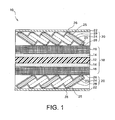
- FIG. 1 is a diagram illustrating a cross-section of a cell 10 for a fuel cell.
- the cell 10 for a fuel cell comprises a membrane electrode assembly (MEA) 18, which integrates an electrolyte membrane 12, catalyst layers 14 and gas diffusion layers 16, and forms an electrode or the like, as well as expanded moldings 20, which are gas channel structures that form gas channels, and separators 22 that separate the fuel gas or oxidant gas fromadjacent cells (not shown in the drawing).
- MEA membrane electrode assembly
- the electrolyte membrane 12 has a function of transporting hydrogen ions generated at the anode electrode side to the cathode electrode side.
- a chemically stable fluororesin such as a perfluorocarbon sulfonic acid ion exchange membrane or the like may be used as the material for the electrolyte membrane 12.
- the catalyst layers 14 have a function of accelerating the oxidation reaction of hydrogen at the anode electrode side and the reduction reaction of oxygen at the cathode electrode side.
- the catalyst layer 14 comprises a catalyst and a catalyst support. In order to maximize the electrode surface area available for reaction, the catalyst is generally in a particulate form that is adhered to the catalyst support.
- a platinum group element having a small activation overpotential such as platinum or the like may be used as the catalyst.
- a carbon material such as carbon black or the like may be used as the catalyst support.
- the gas diffusion layers 16 have a function of diffusing the fuel gas such as hydrogen gas and the oxidant gas such as air through to the respective catalyst layers 14, and a function of transporting electrons.
- a material that exhibits conductivity, such as a carbon fiber woven fabric or a carbon paper or the like, may be used for the gas diffusion layers 16.
- the expanded moldings 20 are laminated onto both surfaces of the membrane electrode assembly 18, and function as gas channel structures that form gas channels.
- the expanded molding 20 is laminated so as to contact the gas diffusion layer 16 of the membrane electrode assembly 18 and the separator 22, and is connected electrically to both the membrane electrode assembly 18 and the separator 22.
- the expanded molding 20 comprises a gas channel substrate 24 that forms gas channels, a conductive layer 26 that is formed on contact portions 25 of the gas channel substrate 24 that contact either the membrane electrode assembly 18 or the separator 22, and a hydrophilic layer 28 that is provided on the gas channel surfaces of the gas channel substrate 24 and is formed from a hydrophilic material.
- the gas channel substrate 24 has a mesh structure comprising a multitude of openings.
- the mesh formed within the gas channel substrate 24 functions as gas channels for the fuel gas or oxidant gas. Because the expanded molding 20 has a multitude of openings, a larger quantity of the fuel gas or the like can contact the membrane electrode assembly 18 and undergo chemical reaction, meaning the electric power generation efficiency of the cell 10 for a fuel cell can be increased.
- the gas channel substrate 24 has contact portions 25 that contact either the membrane electrode assembly 18 or the separator 22 along the length of the membrane electrode assembly 18 or the separator 22, thereby electrically connecting the membrane electrode assembly 18 and the separator 22.
- a plurality of these contact portions 25 may be provided with a predetermined spacing therebetween.
- the spacing between the contact portions 25 can be set, for example, within a range from 600 to 800 ⁇ m.
- the use of an expanded metal prescribed in JIS G 3351, or a metal lath or porous metal substance prescribed in JIS A 5505 or the like is preferable.
- these expanded metals and porous metal substances and the like comprise a multitude of openings.
- the gas channel substrate 24 is not necessarily restricted to expanded metals and the like, and may also employ some other form of molding such as a punched metal or the like.
- the gas channel substrate 24 is preferably formed from a titanium material such as titanium or a titanium alloy, or a stainless steel such as SUS316L or SUS304 or the like.
- a titanium material such as titanium or a titanium alloy, or a stainless steel such as SUS316L or SUS304 or the like.
- these metal materials have a high mechanical strength, and include an inactive coating such as a passivation film comprising a stable oxide (such as TiO, Ti 2 O 3 or TiO 2 , CrO 2 , CrO or Cr 2 O 3 ) formed on the metal surface, and therefore exhibit excellent corrosion resistance.
- a passivation film comprising a stable oxide (such as TiO, Ti 2 O 3 or TiO 2 , CrO 2 , CrO or Cr 2 O 3 ) formed on the metal surface, and therefore exhibit excellent corrosion resistance.
- a stable oxide such as TiO, Ti 2 O 3 or TiO 2 , CrO 2 , CrO or Cr 2 O 3
- the conductive layer 26 is formed from a conductor on the contact portions 25 of the gas channel substrate 24 that contact either the membrane electrode assembly 18 or the separator 22, and has the function of reducing the contact resistance between the expanded molding 20 and the membrane electrode assembly 18, and between the expanded molding 20 and the separator 22.
- the conductive layer 26 is preferably formed from a metal material. The reason for this preference is that metal materials are conductors, and because the gas channel substrate 24 is also formed from a metal material, forming the conductive layer 26 from a metal material yields improved adhesion between the gas channel substrate 24 and the conductive layer 26 compared with the case where the conductive layer 26 is formed from a different material such as a carbon material or the like. Of course, depending on other conditions, an organic conductor or the like may also be used for the conductive layer 26.
- the conductive layer 26 is preferably formed from a metal material conductor such as gold (Au), silver (Ag), copper (Cu), platinum (Pt), rhodium (Rh), iridium (Ir) or palladium (Pd) or the like.
- a metal material conductor such as gold (Au), silver (Ag), copper (Cu), platinum (Pt), rhodium (Rh), iridium (Ir) or palladium (Pd) or the like.
- gold (Au) exhibits superior corrosion resistance and also has excellent electrical conductivity, and is therefore particularly desirable as the metal material for forming the conductive layer 26.
- the conductive layer 26 may also be formed from an alloy of gold (Au) and platinum (Pt) or the like.
- the conductive layer 26 is formed on the contact portions 25 of the gas channel substrate 24 that contact the membrane electrode assembly 18 or the separator 22. In this manner, by forming the conductive layer 26 on the contact portions 25 of the gas channel substrate 24, the amount used of the conductor such as gold (Au) or the like can be reduced. Further, the conductive layer 26 is preferably formed only on the contact portions 25 of the gas channel substrate 24. By forming the conductive layer 26 only on the contact portions 25 of the gas channel substrate 24, the amount used of the conductor such as gold (Au) or the like can be further reduced.
- the conductive layer 26 is formed with a thickness of not less than 2 nm and not more than 500 nm, and is preferably formed with a thickness of not less than 10 nm and not more than 100 nm.
- the hydrophilic layer 28 is formed from a hydrophilic material on the gas channel surfaces of the gas channel substrate 24. By providing the hydrophilic layer 28 on the gas channel surfaces that do not contact the separator 22, the water discharge properties for the generated water can be improved, and the electric power generation efficiency of the cell 10 for a fuel cell can be enhanced.
- a titanium oxide such as titanium dioxide (TiO 2 ) may be used as the hydrophilic material. The reason for this preference is that titanium oxides exhibit a hydrophilic effect via a photocatalytic action. Of course, depending on other conditions, the hydrophilic material is not necessarily restricted to titanium oxides.
- the hydrophilic layer 28 is typically formed with a thickness of 0.1 to 1, 000 nm, and is preferably formed with a thickness of 2 to 10 nm.
- the separators 22 are laminated to the expanded moldings 20, and have the function of separating the fuel gas and oxidant gas in adjacent cells (not shown in the drawings). Furthermore, the separators 22 also have the function of electrically connecting adjacent cells (not shown in the drawings).
- the separators 22 are preferably molded from a titanium material such as titanium or a titanium alloy, or a stainless steel such as SUS316L or SUS304 or the like. As described above, the reason for this preference is that these metal materials have a high mechanical strength, and include an inactive coating such as a passivation film comprising a stable oxide formed on the metal surface, and therefore exhibit excellent corrosion resistance.
- an austenite stainless steel or ferrite stainless steel or the like may be used.
- the metal material that is molded to form the separators 22 need not necessarily be restricted to titanium and stainless steel and the like, and other metal materials may also be used.
- a titanium sheet or stainless steel sheet or the like is typically used for the separators 22.
- the membrane electrode assembly 18 is molded by laminating the catalyst layers 14 to both surfaces of the electrolyte membrane 12, laminating a gas diffusion layer 16 to each of the catalyst layers 14, and then performing thermocompression bonding with a heat press or the like.
- the method of molding the membrane electrode assembly 18 is not restricted to the above molding method.
- the method of molding the expanded moldings 20 comprises a gas channel substrate formation step, a pretreatment step, a conductive layer formation step, and a hydrophilic layer formation step.
- the gas channel substrate formation step is a step of forming the gas channel substrate 24 from a metal material.
- the gas channel substrate 24 such as an expanded metal is molded by subjecting a titanium sheet or stainless steel sheet or the like to cutting and expansion processing or the like.
- the expanded metal may be molded as a single integrated unit, for example, by inserting zigzag-shaped cuts within the titanium sheet or stainless steel sheet or the like, while simultaneously pushing and expanding the cuts to stretch the sheet into a mesh-like structure.
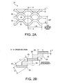
- FIG. 2A and FIG. 2B are diagrams illustrating the structure of a gas channel substrate 24 that employs an expanded metal, wherein FIG. 2A is a schematic illustration of the gas channel substrate 24, and FIG. 2B is a cross-sectional view along the direction A-A.
- the gas channel substrate 24 comprises a plurality of strand portions 30 and a plurality of bond portions 32, and has a mesh structure comprising a multitude of openings.
- FIG. 3 is a diagram illustrating the structure of a gas channel substrate 24 that uses a porous metal substance 34. As illustrated in FIG. 3 , a plurality of openings are provided within the porous metal substance 34 and form gas channels.
- the pretreatment step is a step of pretreating the gas channel substrate 24.
- the pretreatment of the gas channel substrate 24 includes a cleaning treatment, a neutralization treatment, and an acid washing treatment.
- the gas channel substrate 24 is subjected to a cleaning treatment by alkali dipping degreasing or the like, thereby removing oil components and the like adhered to the surface of the gas channel substrate 24.
- the cleaned gas channel substrate 24 is then dipped in a neutralizing solution to neutralize the alkali solution.
- a sulfuric acid solution, hydrochloric acid solution or nitric acid solution or the like may be used as the neutralizing solution.
- the neutralized gas channel substrate 24 is then subjected to an acid washing treatment, thereby removing the passivation film formed on the surface of the gas channel substrate 24.
- the acid washing treatment may be conducted by dipping the gas channel substrate 24 in a solution containing a fluoride, such as a nitric hydrofluoric acid solution or a hydrofluoric acid solution or the
- the conductive layer formation step is a step of forming the conductive layer 26 from a conductor such as gold (Au) or the like on the contact portions 25 of the pretreated gas channel substrate 24.
- This coating of gold (Au) or the like can be formed, for example, using an electroplating method.
- a typical gold (Au), silver (Ag) or copper (Cu) electroplating method may be used for the electroplating.
- a gold plating bath comprising gold potassium cyanide or gold sodium sulfite or the like may be used.
- an alkaline plating bath, a neutral plating bath or an acidic plating bath may be used for the gold plating bath.
- the particle size of the gold (Au) particles or the like that form the conductive layer 26 may be controlled by altering the current density or the plating treatment time, or by adding additives or the like.
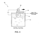
- FIG. 4 is a diagram illustrating the structure of a plating apparatus 50.
- the plating apparatus 50 comprises a plating liquid tank 52, a first roller 54 that lifts up the plating liquid, and a second roller 56 that opposes the first roller 54 with the gas channel substrate 24 sandwiched therebetween.
- the first roller 54 and the second roller 56 are connected to an electrical power source.
- a conductor is plated onto the contact portions 25 of the gas channel substrate 24.
- the other surface of the gas channel substrate 24 is also plated with the conductor via contact with the first roller 54.
- the conductive layer 26 is formed from the conductor on the contact portions 25 of the gas channel substrate 24 that contact the membrane electrode assembly 18 and the separator 22.
- the conductive layer 26 can be formed on the contact portions 25 without requiring masking or the like of the portions other than the contact portions 25, and therefore production costs can be reduced.
- FIG. 5 is a diagram illustrating the gas channel substrate 24 having the conductive layer 26 formed thereon.
- the conductive layer 26 of gold (Au) or the like is formed on the contact portions 25 that contact the membrane electrode assembly 18 and the separator 22.
- the technique used for forming the conductive layer is not restricted to the type of plating method described above, and other coating techniques such as physical vapor deposition methods (PVD methods), chemical vapor deposition methods (CVD methods), coating methods, and inkjet methods may also be used.
- PVD methods physical vapor deposition methods
- CVD methods chemical vapor deposition methods
- a sputtering or ion plating technique or the like can be used for forming the coating of gold (Au) or the like.
- a slurry may be prepared by dispersing particles of the gold (Au) or the like in a binder such as an organic solvent, and this slurry containing the dispersed particles of gold (Au) or the like may then be applied to form a coating.
- an inkjet method coating may be performed using a metal ink containing ultra fine particles of gold (Au) or the like dispersed therein.
- the hydrophilic layer formation step is a step of forming the hydrophilic layer 28, either from a hydrophilic material or via a hydrophilic treatment, on the gas channel surfaces of the gas channel substrate 24.
- the hydrophilic layer 28 may be formed, for example, by coating or sputtering a hydrophilic material onto the gas channel surfaces of the gas channel substrate 24.
- the hydrophilic layer 28 is preferably formed from titanium oxide (TiO 2 ), by subjecting the gas channel substrate 24 having the conductive layer 26 formed thereon to a hydrophilic treatment by heating at a temperature of 250 to 800°C within an oxidizing atmosphere.
- FIG. 6 is a diagram illustrating the structure of the expanded molding 20.
- the hydrophilic layer 28 is formed on the gas channel surfaces other than the contact portions 25.
- Molding of the separators 22 can generally be conducted by subjecting a metal material to machining such as cutting work or plastic working such as press working.
- machining such as cutting work or plastic working such as press working.
- the method used for molding the separators 22 is not restricted to the working methods mentioned above.
- the assembly step is a step of laminating together the membrane electrode assembly 18, the expanded moldings 20 and the separators 22, thus assembling a preliminary molding of the cell for a fuel cell.
- the expanded moldings 20 are first laminated to both surfaces of the membrane electrode assembly 18, and the separators 22 are then laminated to the expanded moldings 20 to complete assembly of the preliminary molding of the cell for a fuel cell.
- the cell 10 for a fuel cell is then produced by bonding the outer peripheral surfaces of this preliminary molding of the cell for a fuel cell with an adhesive or the like.
- the conductive layer of gold (Au) or the like is only formed on the contact portions with the membrane electrode assembly and the separator, the amount used of the conductor such as gold (Au) or the like can be reduced, enabling the production costs of the cell for a fuel cell to be kept low.
- An expanded metal formed from titanium was used as the gas channel substrate 24 of the expanded molding.
- the expanded metal was subjected to a pretreatment that included cleaning by alkali dipping degreasing, neutralizing using a sulfuric acid solution, and then acid washing in a nitric hydrofluoric acid solution.
- the contact portions of the pretreated expanded metal were plated by gold (Au) electroplating, thus forming a gold (Au) plating layer as the conductive layer.
- the plating apparatus illustrated in FIG. 4 was used for forming the gold (Au) plating layer.
- the thickness of the gold (Au) plating layer was set to 10 nm, whereas in the cell for a fuel cell of example 2 the thickness of the gold (Au) plating layer was set to 100 nm.
- the expanded metal having the gold (Au) plating layer formed thereon was then subjected to a heat treatment by being held for 10 minutes in an atmosphere at 300°C, thereby forming a titanium dioxide (TiO 2 ) layer as the hydrophilic layer on the gas channel surfaces other than the contact portions.
- TiO 2 titanium dioxide
- the membrane electrode assembly and the separators were the same as those used in the cells for fuel cells according to example 1 and example 2.
- An expanded metal molded from titanium was used as the gas channel substrate of the expanded molding.
- the expanded metal was subjected to a pretreatment that included cleaning by alkali dipping degreasing, neutralizing using a sulfuric acid solution, and then acid washing in a nitric hydrofluoric acid solution.
- the pretreated expanded metal were plated by gold (Au) electroplating, thus forming a gold (Au) plating layer as the conductive layer.
- the electroplating was conducted using a dipping method in which the pretreated expanded metal was dipped in a gold plating bath.
- the thickness of the gold (Au) plating layer was set to 10 nm
- the thickness of the gold (Au) plating layer was set to 100 nm.
- a titanium dioxide (TiO 2 ) layer was not formed as a hydrophilic layer.
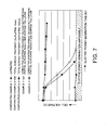
- FIG. 7 is a diagram illustrating the test results from evaluating the electric power generation performance.
- the electric power generation time was plotted along the horizontal axis and the cell voltage was plotted along the vertical axis, with the data for the cell for a fuel cell of example 1 shown as white circles, the data for the cell for a fuel cell of example 2 shown as black circles, the data for the cell for a fuel cell of comparative example 1 shown as black diamonds, the data for the cell for a fuel cell of comparative example 2 shown as white squares, and the data for the cell for a fuel cell of comparative example 3 shown as black squares.
- the cell voltage was low from the start of the test, and yielded a result that represented the lowest electric power generation performance of the five cells for fuel cells.
- the cell voltage decreased after a certain time had elapsed, and the results represented the next lowest electric power generation performance after the cell for a fuel cell according to comparative example 1.
- the cells for fuel cells of example 1 and example 2 suffered almost no reduction in the cell voltage even after a predetermined time had elapsed, and yielded excellent electric power generation performance. This is because in the cells for fuel cells according to example 1 and example 2, the titanium dioxide (TiO 2 ) layer was formed on the gas channel surfaces, thus improving the water discharge properties for the generated water.
- FIG. 8 is a diagram illustrating the comparison of the molding costs for the expanded moldings used within the cells for fuel cells according to example 1 and comparative example 2.
- the molding cost is illustrated along the vertical axis, and the molding costs of the expanded moldings used in the cells for fuel cells of comparative example 2 and example 1 are illustrated in the form of a bar graph.
- the molding costs of the expanded moldings were displayed by specifying the molding cost of the expanded molding used in the cell for a fuel cell according to comparative example 2 as a value of 100, and then determining the molding cost of the expanded molding used in the cell for a fuel cell according to example 1 as a relative value.
- the result revealed a molding cost for the expanded molding used in the cell for a fuel cell according to example 1 of 30, which represents a significantly reduced molding cost compared with that of the expanded molding used in the cell for a fuel cell according to comparative example 2.
- the gold plating was conducted by dipping the expanded metal in a gold plating solution.
- the gold plating layer was formed not only on the contact portions with the membrane electrode assembly and the separator, but also on the gas channel surfaces.
- the gold plating layer was formed only on the contact portions, and no gold plating layer was formed on the gas channel surfaces. Accordingly, in the expanded molding used in the cell for a fuel cell of example 1, the amount used of the plating solution or the like containing a gold (Au) compound or the like was able to be reduced, resulting in a reduction in the production costs.
- a fuel cell of the present invention is effective in any application that utilizes a fuel cell, and is ideal as a fuel cell for mounting in a motor vehicle.
Landscapes
- Chemical & Material Sciences (AREA)
- Life Sciences & Earth Sciences (AREA)
- Engineering & Computer Science (AREA)
- Manufacturing & Machinery (AREA)
- Sustainable Development (AREA)
- Sustainable Energy (AREA)
- Chemical Kinetics & Catalysis (AREA)
- Electrochemistry (AREA)
- General Chemical & Material Sciences (AREA)
- Composite Materials (AREA)
- Fuel Cell (AREA)
- Inert Electrodes (AREA)
Abstract
Description
- The present invention relates to a cell for a fuel cell and a method for producing the same, and relates more particularly to a cell for a fuel cell comprising a membrane electrode assembly, gas channel structures that are laminated to both surfaces of the membrane electrode assembly and form gas channels, and separators that are laminated to the gas channel structures and separate the gases between adjacent cells, as well as a method for producing such a cell for a fuel cell.
- Fuel cells have recently been highlighted as cells that exhibit a high level of efficiency and excellent environmental characteristics. In a fuel cell, generally, the oxygen within air, which functions as an oxidant gas, is subjected to an electrochemical reaction with hydrogen, which functions as a fuel gas, thereby generating electrical energy. As a result of the electrochemical reaction between the hydrogen and oxygen, water is generated.
- Varieties of fuel cell include phosphoric acid fuel cells, molten carbonate fuel cells, solid electrolyte fuel cells, alkali fuel cells and solid polymer fuel cells. Of these, solid polymer fuel cells, which offer certain advantages such as ambient temperature startup and a rapid startup time, are attracting particular attention. This type of solid polymer fuel cell can be used as the power source for moving objects such as vehicles.
- A solid polymer fuel cell is assembled by laminating a plurality of unit cells, a current collector and an end plate and the like. Each unit cell for the fuel cell comprises an electrolyte membrane, catalyst layers, gas diffusion layers and separators.
-
Patent Document 1 discloses a fuel cell having a structure in which a gas diffusion layer comprising a fibrous material is sandwiched between an electrode and a metal separator, wherein a layer of a corrosion-resistant conductive material such as gold (Au) or the like is formed by vapor deposition, sputtering or plating or the like on the gas diffusion layer side of the structure, without forming a plating layer of a corrosion-resistant conductive material such as gold (Au) or the like on the metal separator side of the structure.
Patent Literature 1:JP 2004-178893 A - However, when producing a cell for a fuel cell, as mentioned above, a conductor having a high level of electrical conductivity such as gold (Au) or the like is typically coated onto the surface of the gas diffusion layer or the like, thereby reducing the contact resistance between the gas diffusion layer and the separator. However, when a conductor such as gold (Au) or the like is coated onto the gas diffusion layer, because the gas diffusion layer is generally molded from a porous fibrous material, the gold (Au) or the like tends to penetrate into the interior of the gas diffusion layer, meaning even those regions that do not contact the separator may be coated with the gold (Au) or the like. Because conductors such as gold (Au) are generally very expensive, an increase in the usage amount of gold (Au) or the like may cause an increase in the production costs for the cell for a fuel cell. Furthermore, conductors such as gold (Au) are often hydrophobic, and may therefore impede the discharge of water generated during electric power generation by the fuel cell, resulting in a reduction in the electric power generation efficiency of the fuel cell.
- Accordingly, an advantage of the present invention is to provide a cell for a fuel cell that is capable of keeping production costs low and exhibits improved electric power generation efficiency, as well as a method for producing such a cell for a fuel cell.
- A cell for a fuel cell according to the present invention comprises a membrane electrode assembly, gas channel structures that are laminated to both surfaces of the membrane electrode assembly and form gas channels, and separators that are laminated to the gas channel structures and separate the gases between adjacent cells, wherein the gas channel structures have a gas channel substrate formed from a metal material, a conductive layer that is formed from a conductor on a contact portion of the gas channel substrate that contacts the membrane electrode assembly or the separator, and a hydrophilic layer that is formed from a hydrophilic material on the gas channel surface of the gas channel substrate.
- A method for producing a cell for a fuel cell according to the present invention is a method for producing a cell for a fuel cell that comprises a membrane electrode assembly, gas channel structures that are laminated to both surfaces of the membrane electrode assembly and form gas channels, and separators that are laminated to the gas channel structures and separate the gases between adjacent cells, wherein molding of the gas channel structures comprises a gas channel substrate formation step of forming a gas channel substrate from a metal material, a conductive layer formation step of forming a conductive layer of a conductor on a contact portion of the gas channel substrate that contacts the membrane electrode assembly or the separator, and a hydrophilic layer formation step of forming a hydrophilic layer of a hydrophilic material on the gas channel surface of the gas channel substrate.
- A method for producing a cell for a fuel cell according to another aspect of the present invention is a method for producing a cell for a fuel cell that comprises a membrane electrode assembly, gas channel structures that are laminated to both surfaces of the membrane electrode assembly and form gas channels, and separators that are laminated to the gas channel structures and separate the gases between adjacent cells, wherein molding of the gas channel structures comprises a gas channel substrate formation step of forming a gas channel substrate from a metal material, a conductive layer formation step of forming a conductive layer of a conductor on a contact portion of the gas channel substrate that contacts the membrane electrode assembly or the separator, and a hydrophilic layer formation step of forming a hydrophilic layer on the gas channel surface of the gas channel substrate by performing a hydrophilic treatment.
- A gas channel structure for a fuel cell according to the present invention is laminated to both surfaces of a membrane electrode assembly and forms gas channels, wherein the gas channel structure has a gas channel substrate formed from a metal material, a conductive layer that is formed from a conductor on a contact portion of the gas channel substrate that contacts the membrane electrode assembly or a separator, and a hydrophilic layer that is formed from a hydrophilic material on the gas channel surface of the gas channel substrate.
- As described above, in a cell for a fuel cell according to the present invention and in a method for producing such a cell for a fuel cell, by reducing the amount used of the conductor such as gold (Au) or the like, production costs can be kept low, and electric power generation efficiency can be improved.
-
-
FIG. 1 is a diagram illustrating a cross-section of a cell for a fuel cell according to an embodiment of the present invention. -
FIG. 2A is a diagram illustrating the structure of a gas channel substrate that uses an expanded metal according to an embodiment of the present invention. -
FIG. 2B is a cross-sectional view viewed along the direction A-A inFIG. 2A . -
FIG. 3 is a diagram illustrating the structure of a gas channel substrate that uses a porous metal substance according to an embodiment of the present invention. -
FIG. 4 is a diagram illustrating the structure of a plating apparatus used in an embodiment of the present invention. -
FIG. 5 is a diagram illustrating a gas channel substrate having a conductive layer formed thereon according to an embodiment of the present invention. -
FIG. 6 is a diagram illustrating the structure of an expanded molding according to an embodiment of the present invention. -
FIG. 7 is a diagram illustrating the test results from evaluating the electric power generation performance in an embodiment of the present invention. -
FIG. 8 is a diagram illustrating a comparison of the molding costs for expanded moldings used within cells for fuel cells prepared in an example 1 and a comparative example 2. -
- 10
- Cell for fuel cell
- 12
- Electrolyte membrane
- 14
- Catalyst layer
- 16
- Gas diffusion layer
- 18
- Membrane electrode assembly
- 20
- Expanded molding
- 22
- Separator
- 24
- Gas channel substrate
- 25
- Contact portion
- 26
- Conductive layer
- 28
- Hydrophilic layer
- 30
- Strand portion
- 32
- Bond portion
- 34
- Porous metal substance
- 50
- Plating apparatus
- 52
- Plating liquid tank
- 54
- First roller
- 56
- Second roller
- A detailed description of embodiments according to the present invention is provided below with reference to the drawings.
FIG. 1 is a diagram illustrating a cross-section of acell 10 for a fuel cell. Thecell 10 for a fuel cell comprises a membrane electrode assembly (MEA) 18, which integrates anelectrolyte membrane 12, catalyst layers 14 and gas diffusion layers 16, and forms an electrode or the like, as well as expandedmoldings 20, which are gas channel structures that form gas channels, andseparators 22 that separate the fuel gas or oxidant gas fromadjacent cells (not shown in the drawing). - The
electrolyte membrane 12 has a function of transporting hydrogen ions generated at the anode electrode side to the cathode electrode side. A chemically stable fluororesin such as a perfluorocarbon sulfonic acid ion exchange membrane or the like may be used as the material for theelectrolyte membrane 12. - The catalyst layers 14 have a function of accelerating the oxidation reaction of hydrogen at the anode electrode side and the reduction reaction of oxygen at the cathode electrode side. The
catalyst layer 14 comprises a catalyst and a catalyst support. In order to maximize the electrode surface area available for reaction, the catalyst is generally in a particulate form that is adhered to the catalyst support. For the oxidation reaction of hydrogen and the reduction reaction of oxygen, a platinum group element having a small activation overpotential such as platinum or the like may be used as the catalyst. A carbon material such as carbon black or the like may be used as the catalyst support. - The gas diffusion layers 16 have a function of diffusing the fuel gas such as hydrogen gas and the oxidant gas such as air through to the respective catalyst layers 14, and a function of transporting electrons. A material that exhibits conductivity, such as a carbon fiber woven fabric or a carbon paper or the like, may be used for the gas diffusion layers 16.
- The expanded
moldings 20 are laminated onto both surfaces of themembrane electrode assembly 18, and function as gas channel structures that form gas channels. The expandedmolding 20 is laminated so as to contact thegas diffusion layer 16 of themembrane electrode assembly 18 and theseparator 22, and is connected electrically to both themembrane electrode assembly 18 and theseparator 22. The expandedmolding 20 comprises agas channel substrate 24 that forms gas channels, aconductive layer 26 that is formed oncontact portions 25 of thegas channel substrate 24 that contact either themembrane electrode assembly 18 or theseparator 22, and ahydrophilic layer 28 that is provided on the gas channel surfaces of thegas channel substrate 24 and is formed from a hydrophilic material. - The
gas channel substrate 24 has a mesh structure comprising a multitude of openings. The mesh formed within thegas channel substrate 24 functions as gas channels for the fuel gas or oxidant gas. Because the expandedmolding 20 has a multitude of openings, a larger quantity of the fuel gas or the like can contact themembrane electrode assembly 18 and undergo chemical reaction, meaning the electric power generation efficiency of thecell 10 for a fuel cell can be increased. - The
gas channel substrate 24 hascontact portions 25 that contact either themembrane electrode assembly 18 or theseparator 22 along the length of themembrane electrode assembly 18 or theseparator 22, thereby electrically connecting themembrane electrode assembly 18 and theseparator 22. A plurality of thesecontact portions 25 may be provided with a predetermined spacing therebetween. The spacing between thecontact portions 25 can be set, for example, within a range from 600 to 800 µm. - For the
gas channel substrate 24, the use of an expanded metal prescribed in JIS G 3351, or a metal lath or porous metal substance prescribed in JIS A 5505 or the like is preferable. The reason for this preference is that these expanded metals and porous metal substances and the like comprise a multitude of openings. Of course, depending on other conditions, thegas channel substrate 24 is not necessarily restricted to expanded metals and the like, and may also employ some other form of molding such as a punched metal or the like. - The
gas channel substrate 24 is preferably formed from a titanium material such as titanium or a titanium alloy, or a stainless steel such as SUS316L or SUS304 or the like. The reason for this preference is that these metal materials have a high mechanical strength, and include an inactive coating such as a passivation film comprising a stable oxide (such as TiO, Ti2O3 or TiO2, CrO2, CrO or Cr2O3) formed on the metal surface, and therefore exhibit excellent corrosion resistance. For the stainless steel, an austenite stainless steel or ferrite stainless steel or the like may be used. - The
conductive layer 26 is formed from a conductor on thecontact portions 25 of thegas channel substrate 24 that contact either themembrane electrode assembly 18 or theseparator 22, and has the function of reducing the contact resistance between the expandedmolding 20 and themembrane electrode assembly 18, and between the expandedmolding 20 and theseparator 22. Theconductive layer 26 is preferably formed from a metal material. The reason for this preference is that metal materials are conductors, and because thegas channel substrate 24 is also formed from a metal material, forming theconductive layer 26 from a metal material yields improved adhesion between thegas channel substrate 24 and theconductive layer 26 compared with the case where theconductive layer 26 is formed from a different material such as a carbon material or the like. Of course, depending on other conditions, an organic conductor or the like may also be used for theconductive layer 26. - The
conductive layer 26 is preferably formed from a metal material conductor such as gold (Au), silver (Ag), copper (Cu), platinum (Pt), rhodium (Rh), iridium (Ir) or palladium (Pd) or the like. The reason for this preference is that these metal materials exhibit a high level of electrical conductivity, meaning the contact resistance can be further reduced. Of these metal materials, gold (Au) exhibits superior corrosion resistance and also has excellent electrical conductivity, and is therefore particularly desirable as the metal material for forming theconductive layer 26. Theconductive layer 26 may also be formed from an alloy of gold (Au) and platinum (Pt) or the like. - The
conductive layer 26 is formed on thecontact portions 25 of thegas channel substrate 24 that contact themembrane electrode assembly 18 or theseparator 22. In this manner, by forming theconductive layer 26 on thecontact portions 25 of thegas channel substrate 24, the amount used of the conductor such as gold (Au) or the like can be reduced. Further, theconductive layer 26 is preferably formed only on thecontact portions 25 of thegas channel substrate 24. By forming theconductive layer 26 only on thecontact portions 25 of thegas channel substrate 24, the amount used of the conductor such as gold (Au) or the like can be further reduced. Theconductive layer 26 is formed with a thickness of not less than 2 nm and not more than 500 nm, and is preferably formed with a thickness of not less than 10 nm and not more than 100 nm. - The
hydrophilic layer 28 is formed from a hydrophilic material on the gas channel surfaces of thegas channel substrate 24. By providing thehydrophilic layer 28 on the gas channel surfaces that do not contact theseparator 22, the water discharge properties for the generated water can be improved, and the electric power generation efficiency of thecell 10 for a fuel cell can be enhanced. A titanium oxide such as titanium dioxide (TiO2) may be used as the hydrophilic material. The reason for this preference is that titanium oxides exhibit a hydrophilic effect via a photocatalytic action. Of course, depending on other conditions, the hydrophilic material is not necessarily restricted to titanium oxides. Thehydrophilic layer 28 is typically formed with a thickness of 0.1 to 1, 000 nm, and is preferably formed with a thickness of 2 to 10 nm. - The
separators 22 are laminated to the expandedmoldings 20, and have the function of separating the fuel gas and oxidant gas in adjacent cells (not shown in the drawings). Furthermore, theseparators 22 also have the function of electrically connecting adjacent cells (not shown in the drawings). Theseparators 22 are preferably molded from a titanium material such as titanium or a titanium alloy, or a stainless steel such as SUS316L or SUS304 or the like. As described above, the reason for this preference is that these metal materials have a high mechanical strength, and include an inactive coating such as a passivation film comprising a stable oxide formed on the metal surface, and therefore exhibit excellent corrosion resistance. For the stainless steel, an austenite stainless steel or ferrite stainless steel or the like may be used. Of course, depending on other conditions, the metal material that is molded to form theseparators 22 need not necessarily be restricted to titanium and stainless steel and the like, and other metal materials may also be used. A titanium sheet or stainless steel sheet or the like is typically used for theseparators 22. - Next is a description of a method for producing the
cell 10 for a fuel cell. - The
membrane electrode assembly 18 is molded by laminating the catalyst layers 14 to both surfaces of theelectrolyte membrane 12, laminating agas diffusion layer 16 to each of the catalyst layers 14, and then performing thermocompression bonding with a heat press or the like. Of course, the method of molding themembrane electrode assembly 18 is not restricted to the above molding method. - Next is a description of a method of molding the expanded
moldings 20. The method of molding the expandedmoldings 20 comprises a gas channel substrate formation step, a pretreatment step, a conductive layer formation step, and a hydrophilic layer formation step. - The gas channel substrate formation step is a step of forming the
gas channel substrate 24 from a metal material. Thegas channel substrate 24 such as an expanded metal is molded by subjecting a titanium sheet or stainless steel sheet or the like to cutting and expansion processing or the like. The expanded metal may be molded as a single integrated unit, for example, by inserting zigzag-shaped cuts within the titanium sheet or stainless steel sheet or the like, while simultaneously pushing and expanding the cuts to stretch the sheet into a mesh-like structure. -
FIG. 2A and FIG. 2B are diagrams illustrating the structure of agas channel substrate 24 that employs an expanded metal, whereinFIG. 2A is a schematic illustration of thegas channel substrate 24, andFIG. 2B is a cross-sectional view along the direction A-A. As illustrated inFIG. 2A , thegas channel substrate 24 comprises a plurality ofstrand portions 30 and a plurality ofbond portions 32, and has a mesh structure comprising a multitude of openings. Molding may be performed with the plate thickness (t) of thestrand portions 30 within thegas channel substrate 24, the short way midpoint distance (SW) of the mesh, the long way midpoint distance (LW) of the mesh, the short way midpoint distance (SW), and the thickness (X) of thegas channel substrate 24 all set to predetermined values. Furthermore,FIG. 3 is a diagram illustrating the structure of agas channel substrate 24 that uses aporous metal substance 34. As illustrated inFIG. 3 , a plurality of openings are provided within theporous metal substance 34 and form gas channels. - The pretreatment step is a step of pretreating the
gas channel substrate 24. The pretreatment of thegas channel substrate 24 includes a cleaning treatment, a neutralization treatment, and an acid washing treatment. First, thegas channel substrate 24 is subjected to a cleaning treatment by alkali dipping degreasing or the like, thereby removing oil components and the like adhered to the surface of thegas channel substrate 24. The cleanedgas channel substrate 24 is then dipped in a neutralizing solution to neutralize the alkali solution. A sulfuric acid solution, hydrochloric acid solution or nitric acid solution or the like may be used as the neutralizing solution. The neutralizedgas channel substrate 24 is then subjected to an acid washing treatment, thereby removing the passivation film formed on the surface of thegas channel substrate 24. The acid washing treatment may be conducted by dipping thegas channel substrate 24 in a solution containing a fluoride, such as a nitric hydrofluoric acid solution or a hydrofluoric acid solution or the like. - The conductive layer formation step is a step of forming the
conductive layer 26 from a conductor such as gold (Au) or the like on thecontact portions 25 of the pretreatedgas channel substrate 24. This coating of gold (Au) or the like can be formed, for example, using an electroplating method. A typical gold (Au), silver (Ag) or copper (Cu) electroplating method may be used for the electroplating. For example, in the case where a gold (Au) plating layer is coated onto thecontact portions 25 of thegas channel substrate 24 as theconductive layer 26, a gold plating bath comprising gold potassium cyanide or gold sodium sulfite or the like may be used. Further, an alkaline plating bath, a neutral plating bath or an acidic plating bath may be used for the gold plating bath. Furthermore, the particle size of the gold (Au) particles or the like that form theconductive layer 26 may be controlled by altering the current density or the plating treatment time, or by adding additives or the like. -
FIG. 4 is a diagram illustrating the structure of aplating apparatus 50. Theplating apparatus 50 comprises aplating liquid tank 52, afirst roller 54 that lifts up the plating liquid, and asecond roller 56 that opposes thefirst roller 54 with thegas channel substrate 24 sandwiched therebetween. Thefirst roller 54 and thesecond roller 56 are connected to an electrical power source. By adjusting the conditions so that the plating liquid lifted up by thefirst roller 54 contacts thegas channel substrate 24, a conductor is plated onto thecontact portions 25 of thegas channel substrate 24. Following plating of the conductor onto one surface of thegas channel substrate 24 via contact with thefirst roller 54, the other surface of thegas channel substrate 24 is also plated with the conductor via contact with thefirst roller 54. As a result, theconductive layer 26 is formed from the conductor on thecontact portions 25 of thegas channel substrate 24 that contact themembrane electrode assembly 18 and theseparator 22. By using the plating apparatus described above, theconductive layer 26 can be formed on thecontact portions 25 without requiring masking or the like of the portions other than thecontact portions 25, and therefore production costs can be reduced.FIG. 5 is a diagram illustrating thegas channel substrate 24 having theconductive layer 26 formed thereon. Theconductive layer 26 of gold (Au) or the like is formed on thecontact portions 25 that contact themembrane electrode assembly 18 and theseparator 22. - Of course, the technique used for forming the conductive layer is not restricted to the type of plating method described above, and other coating techniques such as physical vapor deposition methods (PVD methods), chemical vapor deposition methods (CVD methods), coating methods, and inkjet methods may also be used. In a physical vapor deposition method (PVD method), a sputtering or ion plating technique or the like can be used for forming the coating of gold (Au) or the like. In a coating method, a slurry may be prepared by dispersing particles of the gold (Au) or the like in a binder such as an organic solvent, and this slurry containing the dispersed particles of gold (Au) or the like may then be applied to form a coating. Further, in an inkjet method, coating may be performed using a metal ink containing ultra fine particles of gold (Au) or the like dispersed therein.
- The hydrophilic layer formation step is a step of forming the
hydrophilic layer 28, either from a hydrophilic material or via a hydrophilic treatment, on the gas channel surfaces of thegas channel substrate 24. Thehydrophilic layer 28 may be formed, for example, by coating or sputtering a hydrophilic material onto the gas channel surfaces of thegas channel substrate 24. In those cases where thegas channel substrate 24 is formed from a titanium material, thehydrophilic layer 28 is preferably formed from titanium oxide (TiO2), by subjecting thegas channel substrate 24 having theconductive layer 26 formed thereon to a hydrophilic treatment by heating at a temperature of 250 to 800°C within an oxidizing atmosphere. Because the titanium material remains exposed in those regions where theconductive layer 26 has not been formed, the heat treatment in an oxidizing atmosphere oxidizes the titanium material and forms the titanium oxide. This method enables thehydrophilic layer 28 to be formed with comparative ease, enabling the production costs for thecell 10 for a fuel cell to be kept low.FIG. 6 is a diagram illustrating the structure of the expandedmolding 20. Thehydrophilic layer 28 is formed on the gas channel surfaces other than thecontact portions 25. - Next is a description of a method of molding the
separators 22. Molding of theseparators 22 can generally be conducted by subjecting a metal material to machining such as cutting work or plastic working such as press working. Of course, the method used for molding theseparators 22 is not restricted to the working methods mentioned above. - The assembly step is a step of laminating together the
membrane electrode assembly 18, the expandedmoldings 20 and theseparators 22, thus assembling a preliminary molding of the cell for a fuel cell. The expandedmoldings 20 are first laminated to both surfaces of themembrane electrode assembly 18, and theseparators 22 are then laminated to the expandedmoldings 20 to complete assembly of the preliminary molding of the cell for a fuel cell. Thecell 10 for a fuel cell is then produced by bonding the outer peripheral surfaces of this preliminary molding of the cell for a fuel cell with an adhesive or the like. - By adopting the configuration described above, because the conductive layer of gold (Au) or the like is only formed on the contact portions with the membrane electrode assembly and the separator, the amount used of the conductor such as gold (Au) or the like can be reduced, enabling the production costs of the cell for a fuel cell to be kept low.
- By adopting the configuration described above, because a hydrophilic layer such as a titanium oxide (TiO2) layer is formed on the gas channel surfaces of the gas channel structure, the water discharge properties for the generated water are improved, meaning the electric power generation efficiency of the cell for a fuel cell can be enhanced.
- Five types of cells for fuel cells were produced, and each cell was evaluated for electric power generation performance and the like.
- First is a description of the method used for producing the cells for fuel cells of example 1 and example 2. In the membrane electrode assembly, a fluororesin was used for the electrolyte membrane, platinum supported on carbon black was used for the catalyst layers, and carbon fiber was used for the gas diffusion layers. These items were laminated together, and thermocompression bonding using a hot press was used to complete the membrane electrode assembly. Further, a titanium sheet was used for the separators.
- An expanded metal formed from titanium was used as the
gas channel substrate 24 of the expanded molding. The expanded metal was subjected to a pretreatment that included cleaning by alkali dipping degreasing, neutralizing using a sulfuric acid solution, and then acid washing in a nitric hydrofluoric acid solution. Subsequently, the contact portions of the pretreated expanded metal were plated by gold (Au) electroplating, thus forming a gold (Au) plating layer as the conductive layer. The plating apparatus illustrated inFIG. 4 was used for forming the gold (Au) plating layer. In the cell for a fuel cell of example 1 the thickness of the gold (Au) plating layer was set to 10 nm, whereas in the cell for a fuel cell of example 2 the thickness of the gold (Au) plating layer was set to 100 nm. The expanded metal having the gold (Au) plating layer formed thereon was then subjected to a heat treatment by being held for 10 minutes in an atmosphere at 300°C, thereby forming a titanium dioxide (TiO2) layer as the hydrophilic layer on the gas channel surfaces other than the contact portions. Finally, the above membrane electrode assembly, the expanded moldings and the separators were laminated together and assembled, completing production of the cells for fuel cells according to example 1 and example 2. - Next is a description of the method used for producing a cell for a fuel cell according to comparative example 1. The membrane electrode assembly and the separators were the same as those used in the cells for fuel cells according to example 1 and example 2. An expanded metal formed from titanium was used as the gas channel substrate of the expanded molding. The expanded metal was subjected to a pretreatment that included cleaning by alkali dipping degreasing, neutralizing using a sulfuric acid solution, and then acid washing in a nitric hydrofluoric acid solution. However, in the cell for a fuel cell according to comparative example 1, a gold (Au) plating layer and a titanium dioxide (TiO2) layer were not formed on the expanded metal. The remaining production was conducted in the same manner as the production method described for the cells for fuel cells of example 1 and example 2.
- Next is a description of the method used for producing cells for fuel cells according to comparative example 2 and comparative example 3. The membrane electrode assembly and the separators were the same as those used in the cells for fuel cells according to example 1 and example 2. An expanded metal molded from titanium was used as the gas channel substrate of the expanded molding. The expanded metal was subjected to a pretreatment that included cleaning by alkali dipping degreasing, neutralizing using a sulfuric acid solution, and then acid washing in a nitric hydrofluoric acid solution. Subsequently, the pretreated expanded metal were plated by gold (Au) electroplating, thus forming a gold (Au) plating layer as the conductive layer. The electroplating was conducted using a dipping method in which the pretreated expanded metal was dipped in a gold plating bath. In the cell for a fuel cell of comparative example 2 the thickness of the gold (Au) plating layer was set to 10 nm, whereas in the cell for a fuel cell of comparative example 3 the thickness of the gold (Au) plating layer was set to 100 nm. In the cells for fuel cells according to comparative example 2 and comparative example 3, a titanium dioxide (TiO2) layer was not formed as a hydrophilic layer. Finally, the above membrane electrode assembly, the expanded moldings and the separators were laminated together and assembled, completing production of the cells for fuel cells according to comparative example 2 and comparative example 3.
- Tests were conducted to evaluate the electric power generation performance of each of the above five types of cells for fuel cells.
FIG. 7 is a diagram illustrating the test results from evaluating the electric power generation performance. As illustrated inFIG. 7 , the electric power generation time was plotted along the horizontal axis and the cell voltage was plotted along the vertical axis, with the data for the cell for a fuel cell of example 1 shown as white circles, the data for the cell for a fuel cell of example 2 shown as black circles, the data for the cell for a fuel cell of comparative example 1 shown as black diamonds, the data for the cell for a fuel cell of comparative example 2 shown as white squares, and the data for the cell for a fuel cell of comparative example 3 shown as black squares. - In the cell for a fuel cell according to comparative example 1, the cell voltage was low from the start of the test, and yielded a result that represented the lowest electric power generation performance of the five cells for fuel cells. In the cells for fuel cells of comparative example 2 and comparative example 3, the cell voltage decreased after a certain time had elapsed, and the results represented the next lowest electric power generation performance after the cell for a fuel cell according to comparative example 1. In contrast, the cells for fuel cells of example 1 and example 2 suffered almost no reduction in the cell voltage even after a predetermined time had elapsed, and yielded excellent electric power generation performance. This is because in the cells for fuel cells according to example 1 and example 2, the titanium dioxide (TiO2) layer was formed on the gas channel surfaces, thus improving the water discharge properties for the generated water.
- Next, a comparison was conducted of the molding costs for the expanded moldings used in the cells for fuel cells according to example 1 and comparative example 2.
FIG. 8 is a diagram illustrating the comparison of the molding costs for the expanded moldings used within the cells for fuel cells according to example 1 and comparative example 2. InFIG. 8 , the molding cost is illustrated along the vertical axis, and the molding costs of the expanded moldings used in the cells for fuel cells of comparative example 2 and example 1 are illustrated in the form of a bar graph. The molding costs of the expanded moldings were displayed by specifying the molding cost of the expanded molding used in the cell for a fuel cell according to comparative example 2 as a value of 100, and then determining the molding cost of the expanded molding used in the cell for a fuel cell according to example 1 as a relative value. The result revealed a molding cost for the expanded molding used in the cell for a fuel cell according to example 1 of 30, which represents a significantly reduced molding cost compared with that of the expanded molding used in the cell for a fuel cell according to comparative example 2. - In the expanded molding used in the cell for a fuel cell of comparative example 2, the gold plating was conducted by dipping the expanded metal in a gold plating solution. As a result, the gold plating layer was formed not only on the contact portions with the membrane electrode assembly and the separator, but also on the gas channel surfaces. In contrast, in the expanded molding used in the cell for a fuel cell of example 1, the gold plating layer was formed only on the contact portions, and no gold plating layer was formed on the gas channel surfaces. Accordingly, in the expanded molding used in the cell for a fuel cell of example 1, the amount used of the plating solution or the like containing a gold (Au) compound or the like was able to be reduced, resulting in a reduction in the production costs.
- The present invention has been described in detail above, but the scope of the present invention is not restricted by the above description.
- Further, the detailed description, claims, drawings and abstract of the inventions disclosed in Japanese Patent Application No.
2007-287352, filed on November 5, 2007 - A fuel cell of the present invention is effective in any application that utilizes a fuel cell, and is ideal as a fuel cell for mounting in a motor vehicle.
Claims (4)
- A cell for a fuel cell, comprising
a membrane electrode assembly,
gas channel structures that are laminated to both surfaces of the membrane electrode assembly and form gas channels, and
separators that are laminated to the gas channel structures and separate gases between adjacent cells, wherein
the gas channel structures comprise
a gas channel substrate formed from a metal material,
a conductive layer that is formed from a conductor on a contact portion of the gas channel substrate that contacts the membrane electrode assembly or the separator, and
a hydrophilic layer that is formed from a hydrophilic material on a gas channel surface of the gas channel substrate. - A method for producing a cell for a fuel cell that comprises a membrane electrode assembly,
gas channel structures that are laminated to both surfaces of the membrane electrode assembly and form gas channels, and
separators that are laminated to the gas channel structures and separate gases between adjacent cells, wherein
molding of the gas channel structures comprises
a gas channel substrate formation step of forming a gas channel substrate from a metal material,
a conductive layer formation step of forming a conductive layer of a conductor on a contact portion of the gas channel substrate that contacts the membrane electrode assembly or the separator,
and
a hydrophilic layer formation step of forming a hydrophilic layer of a hydrophilic material on a gas channel surface of the gas channel substrate. - A method for producing a cell for a fuel cell that comprises a membrane electrode assembly,
gas channel structures that are laminated to both surfaces of the membrane electrode assembly and form gas channels, and
separators that are laminated to the gas channel structures and separate gases between adjacent cells, wherein
molding of the gas channel structures comprises
a gas channel substrate formation step of forming a gas channel substrate from a metal material,
a conductive layer formation step of forming a conductive layer of a conductor on a contact portion of the gas channel substrate that contacts the membrane electrode assembly or the separator, and
a hydrophilic layer formation step of forming a hydrophilic layer on a gas channel surface of the gas channel substrate by performing a hydrophilic treatment. - A gas channel structure for a fuel cell that is laminated to both surfaces of a membrane electrode assembly and forms gas channels, wherein
the gas channel structure comprises
a gas channel substrate formed from a metal material,
a conductive layer that is formed from a conductor on a contact portion of the gas channel substrate that contacts the membrane electrode assembly or the separator, and
a hydrophilic layer that is formed from a hydrophilic material on a gas channel surface of the gas channel substrate.
Applications Claiming Priority (2)
| Application Number | Priority Date | Filing Date | Title |
|---|---|---|---|
| JP2007287352A JP4434264B2 (en) | 2007-11-05 | 2007-11-05 | Fuel cell, fuel cell manufacturing method and fuel cell gas flow channel structure |
| PCT/JP2008/070017 WO2009060816A1 (en) | 2007-11-05 | 2008-11-04 | Cell for fuel battery, method for producing the same, and gas channel structure for fuel battery |
Publications (3)
| Publication Number | Publication Date |
|---|---|
| EP2219254A1 true EP2219254A1 (en) | 2010-08-18 |
| EP2219254A4 EP2219254A4 (en) | 2012-01-11 |
| EP2219254B1 EP2219254B1 (en) | 2016-08-31 |
Family
ID=40625707
Family Applications (1)
| Application Number | Title | Priority Date | Filing Date |
|---|---|---|---|
| EP08847650.2A Not-in-force EP2219254B1 (en) | 2007-11-05 | 2008-11-04 | Cell for fuel cell, method for producing the same, and gas channel structure for fuel cell |
Country Status (6)
| Country | Link |
|---|---|
| US (1) | US8945796B2 (en) |
| EP (1) | EP2219254B1 (en) |
| JP (1) | JP4434264B2 (en) |
| CN (1) | CN101971396B (en) |
| CA (1) | CA2704776C (en) |
| WO (1) | WO2009060816A1 (en) |
Cited By (3)
| Publication number | Priority date | Publication date | Assignee | Title |
|---|---|---|---|---|
| DE102010003171B4 (en) * | 2009-03-23 | 2014-05-15 | Honda Motor Co., Ltd. | Manufacturing method for a fuel cell separator |
| WO2019029769A1 (en) * | 2017-08-11 | 2019-02-14 | Schaeffler Technologies AG & Co. KG | METHOD FOR PRODUCING COMPONENTS AND COMPONENTS PRODUCED THEREBY |
| EP4428959A1 (en) * | 2023-03-08 | 2024-09-11 | Melicon GmbH | Bipolar plate electrode assembly and method |
Families Citing this family (10)
| Publication number | Priority date | Publication date | Assignee | Title |
|---|---|---|---|---|
| US8506787B2 (en) | 2009-07-31 | 2013-08-13 | Infinity Fuel Cell And Hydrogen, Inc. | Electrochemical cell |
| KR101165542B1 (en) | 2009-08-21 | 2012-07-16 | 현대하이스코 주식회사 | Metal separator for fuel cell having coating film and method for the same |
| KR101319384B1 (en) | 2010-08-03 | 2013-10-22 | 삼성에스디아이 주식회사 | Separator for fuel cell, and fuel cell system including the same |
| JP5549478B2 (en) * | 2010-08-26 | 2014-07-16 | トヨタ紡織株式会社 | Fuel cell |
| KR101321463B1 (en) * | 2012-06-28 | 2013-10-28 | 주식회사 셀모티브 | Fuel cell and method of manufacturing thereof |
| KR101729037B1 (en) | 2015-12-17 | 2017-04-24 | 주식회사 포스코 | Stainless steel with improved hydrophilicity and corrosion resistance for pemfc separator and method of manufacturing the same |
| KR101742088B1 (en) | 2015-12-23 | 2017-06-01 | 주식회사 포스코 | Stainless steel with improved hydrophilicity and contact resistance for pemfc separator and method of manufacturing the same |
| JP6315007B2 (en) * | 2016-02-23 | 2018-04-25 | トヨタ自動車株式会社 | Battery module |
| KR102291510B1 (en) * | 2016-12-28 | 2021-08-19 | 닛폰세이테츠 가부시키가이샤 | Titanium Material, Separator, Cell, and Polymer Fuel Cell |
| WO2022114671A1 (en) | 2020-11-24 | 2022-06-02 | 주식회사 포스코 | Stainless steel for fuel cell separator with excellent surface hydrophilicity and electrical conductivity, and manufacturing method thereof |
Family Cites Families (22)
| Publication number | Priority date | Publication date | Assignee | Title |
|---|---|---|---|---|
| US3607411A (en) * | 1968-03-21 | 1971-09-21 | Exmet Corp | Prestretched expanded metal and method of making it |
| US6202271B1 (en) * | 1998-03-13 | 2001-03-20 | Matsushita Electric Industrial Co., Ltd. | Method and apparatus for manufacturing expanded mesh sheet and battery using this expanded mesh sheet |
| EP1009051A2 (en) | 1998-12-08 | 2000-06-14 | General Motors Corporation | Liquid cooled bipolar plate consisting of glued plates for PEM fuel cells |
| JP3997660B2 (en) * | 1998-12-21 | 2007-10-24 | トヨタ自動車株式会社 | Metal separator for fuel cell and manufacturing method thereof |
| JP2001093539A (en) | 1999-09-28 | 2001-04-06 | Matsushita Electric Ind Co Ltd | Solid polymer electrolyte fuel cell |
| WO2001059862A2 (en) | 2000-02-11 | 2001-08-16 | The Texas A & M University System | Electroconductive fuel cell component with directly bonded layers and method for making same |
| US6811918B2 (en) | 2001-11-20 | 2004-11-02 | General Motors Corporation | Low contact resistance PEM fuel cell |
| JP3891069B2 (en) | 2002-08-09 | 2007-03-07 | トヨタ自動車株式会社 | Fuel cell separator |
| JP4367062B2 (en) * | 2002-10-18 | 2009-11-18 | 日立電線株式会社 | Fuel cell separator |
| US20040081879A1 (en) * | 2002-10-18 | 2004-04-29 | Mineo Washima | Fuel cell bipolarplate |
| JP2004178893A (en) | 2002-11-26 | 2004-06-24 | Toyota Motor Corp | Gas diffusion layer for fuel cell and fuel cell having the gas diffusion layer |
| JP2005209470A (en) * | 2004-01-22 | 2005-08-04 | Equos Research Co Ltd | Fuel cell |
| DE102004009869B4 (en) * | 2004-02-26 | 2010-12-30 | Reinz-Dichtungs-Gmbh | Contact plate for fuel cells, fuel cell and fuel cell stack and method for producing a contact plate |
| US20050244689A1 (en) * | 2004-04-28 | 2005-11-03 | Munehisa Horiguchi | Separator and fuel cell system using that separator |
| JP2005340179A (en) | 2004-04-28 | 2005-12-08 | Equos Research Co Ltd | Separator and fuel cell device using the same |
| US7709145B2 (en) * | 2004-11-12 | 2010-05-04 | Gm Global Technology Operations, Inc. | Hydrophilic surface modification of bipolar plate |
| JP2007103075A (en) | 2005-09-30 | 2007-04-19 | Nikko Kinzoku Kk | Substrate and material for separator of polymer electrolyte fuel cell, and material therefor |
| JP2007134145A (en) * | 2005-11-10 | 2007-05-31 | Toyota Motor Corp | Metal separator for fuel cell and manufacturing method thereof |
| JP4859189B2 (en) | 2005-11-29 | 2012-01-25 | Jx日鉱日石金属株式会社 | Titanium or titanium alloy material with precious metal plating |
| JP4445934B2 (en) * | 2006-02-10 | 2010-04-07 | トヨタ車体株式会社 | Method for forming gas diffusion layer for fuel cell |
| US7740988B2 (en) * | 2006-03-31 | 2010-06-22 | Fuelcell Energy, Inc. | Fuel cell plate structure having baffles in wet seal area |
| JP4678359B2 (en) * | 2006-10-25 | 2011-04-27 | トヨタ車体株式会社 | Fuel cell |
-
2007
- 2007-11-05 JP JP2007287352A patent/JP4434264B2/en not_active Expired - Fee Related
-
2008
- 2008-11-04 WO PCT/JP2008/070017 patent/WO2009060816A1/en not_active Ceased
- 2008-11-04 CA CA2704776A patent/CA2704776C/en not_active Expired - Fee Related
- 2008-11-04 CN CN200880114180.9A patent/CN101971396B/en not_active Expired - Fee Related
- 2008-11-04 EP EP08847650.2A patent/EP2219254B1/en not_active Not-in-force
- 2008-11-04 US US12/741,286 patent/US8945796B2/en not_active Expired - Fee Related
Cited By (3)
| Publication number | Priority date | Publication date | Assignee | Title |
|---|---|---|---|---|
| DE102010003171B4 (en) * | 2009-03-23 | 2014-05-15 | Honda Motor Co., Ltd. | Manufacturing method for a fuel cell separator |
| WO2019029769A1 (en) * | 2017-08-11 | 2019-02-14 | Schaeffler Technologies AG & Co. KG | METHOD FOR PRODUCING COMPONENTS AND COMPONENTS PRODUCED THEREBY |
| EP4428959A1 (en) * | 2023-03-08 | 2024-09-11 | Melicon GmbH | Bipolar plate electrode assembly and method |
Also Published As
| Publication number | Publication date |
|---|---|
| CN101971396B (en) | 2015-01-21 |
| EP2219254B1 (en) | 2016-08-31 |
| CA2704776C (en) | 2013-05-28 |
| EP2219254A4 (en) | 2012-01-11 |
| WO2009060816A1 (en) | 2009-05-14 |
| US20100239949A1 (en) | 2010-09-23 |
| JP4434264B2 (en) | 2010-03-17 |
| CA2704776A1 (en) | 2009-05-14 |
| CN101971396A (en) | 2011-02-09 |
| JP2009117114A (en) | 2009-05-28 |
| US8945796B2 (en) | 2015-02-03 |
Similar Documents
| Publication | Publication Date | Title |
|---|---|---|
| EP2219254B1 (en) | Cell for fuel cell, method for producing the same, and gas channel structure for fuel cell | |
| US8815471B2 (en) | Method of manufacturing fuel cell separator, fuel cell separator and fuel cell, including gold plating | |
| US9793554B2 (en) | Fuel cell separator and fuel cell | |
| US6972162B2 (en) | Solid polymer electrolyte fuel cell unit | |
| EP2772974B1 (en) | Porous current collector, method for manufacturing same, and fuel cell that uses porous current collector | |
| JP2008243394A (en) | Method for manufacturing fuel cell | |
| EP1492186A1 (en) | Cell unit of solid polymeric electrolyte type fuel cell | |
| JP2002063914A (en) | Gas separator for fuel cell, method of manufacturing fuel cell separator, and fuel cell | |
| JP4488059B2 (en) | Manufacturing method of fuel cell separator | |
| JP2000048833A (en) | Fuel cell | |
| JP4482352B2 (en) | Polymer electrolyte fuel cell | |
| JP2009087909A (en) | Manufacturing method of fuel cell separator | |
| WO2009034845A1 (en) | Process for producing separator for fuel cell | |
| JP2007128908A (en) | Cell unit of solid polymer electrolyte fuel cell | |
| JP2009043504A (en) | Fuel cell and manufacturing method thereof | |
| JP5466269B2 (en) | Fuel cell separator and fuel cell | |
| JP2010092699A (en) | Fuel cell | |
| JPWO2004054019A1 (en) | Method for forming reaction layer on electrolyte membrane of fuel cell and electrolyte membrane | |
| JP2009104932A (en) | Fuel cell separator and method for producing the same | |
| JP5497865B2 (en) | Manufacturing method of fuel cell separator | |
| JPH04141957A (en) | Manufacture of oxygen gas electrode of solid electrolyte fuel cell |
Legal Events
| Date | Code | Title | Description |
|---|---|---|---|
| PUAI | Public reference made under article 153(3) epc to a published international application that has entered the european phase |
Free format text: ORIGINAL CODE: 0009012 |
|
| 17P | Request for examination filed |
Effective date: 20100607 |
|
| AK | Designated contracting states |
Kind code of ref document: A1 Designated state(s): AT BE BG CH CY CZ DE DK EE ES FI FR GB GR HR HU IE IS IT LI LT LU LV MC MT NL NO PL PT RO SE SI SK TR |
|
| AX | Request for extension of the european patent |
Extension state: AL BA MK RS |
|
| DAX | Request for extension of the european patent (deleted) | ||
| A4 | Supplementary search report drawn up and despatched |
Effective date: 20111213 |
|
| RIC1 | Information provided on ipc code assigned before grant |
Ipc: H01M 8/10 20060101ALI20111207BHEP Ipc: H01M 8/02 20060101AFI20111207BHEP |
|
| 17Q | First examination report despatched |
Effective date: 20120829 |
|
| RAP1 | Party data changed (applicant data changed or rights of an application transferred) |
Owner name: TOYOTA JIDOSHA KABUSHIKI KAISHA |
|
| RIN1 | Information on inventor provided before grant (corrected) |
Inventor name: OOMORI, HIDEYO Inventor name: MAEDA, KUROUDO |
|
| GRAP | Despatch of communication of intention to grant a patent |
Free format text: ORIGINAL CODE: EPIDOSNIGR1 |
|
| INTG | Intention to grant announced |
Effective date: 20160212 |
|
| GRAJ | Information related to disapproval of communication of intention to grant by the applicant or resumption of examination proceedings by the epo deleted |
Free format text: ORIGINAL CODE: EPIDOSDIGR1 |
|
| GRAP | Despatch of communication of intention to grant a patent |
Free format text: ORIGINAL CODE: EPIDOSNIGR1 |
|
| GRAR | Information related to intention to grant a patent recorded |
Free format text: ORIGINAL CODE: EPIDOSNIGR71 |
|
| GRAS | Grant fee paid |
Free format text: ORIGINAL CODE: EPIDOSNIGR3 |
|
| INTG | Intention to grant announced |
Effective date: 20160701 |
|
| GRAA | (expected) grant |
Free format text: ORIGINAL CODE: 0009210 |
|
| INTC | Intention to grant announced (deleted) | ||
| AK | Designated contracting states |
Kind code of ref document: B1 Designated state(s): AT BE BG CH CY CZ DE DK EE ES FI FR GB GR HR HU IE IS IT LI LT LU LV MC MT NL NO PL PT RO SE SI SK TR |
|
| INTG | Intention to grant announced |
Effective date: 20160722 |
|
| REG | Reference to a national code |
Ref country code: CH Ref legal event code: EP Ref country code: GB Ref legal event code: FG4D |
|
| REG | Reference to a national code |
Ref country code: IE Ref legal event code: FG4D |
|
| REG | Reference to a national code |
Ref country code: DE Ref legal event code: R096 Ref document number: 602008046051 Country of ref document: DE |
|
| REG | Reference to a national code |
Ref country code: FR Ref legal event code: PLFP Year of fee payment: 9 |
|
| REG | Reference to a national code |
Ref country code: AT Ref legal event code: REF Ref document number: 825679 Country of ref document: AT Kind code of ref document: T Effective date: 20161015 |
|
| REG | Reference to a national code |
Ref country code: LT Ref legal event code: MG4D |
|
| REG | Reference to a national code |
Ref country code: NL Ref legal event code: MP Effective date: 20160831 |
|
| REG | Reference to a national code |
Ref country code: AT Ref legal event code: MK05 Ref document number: 825679 Country of ref document: AT Kind code of ref document: T Effective date: 20160831 |
|
| PG25 | Lapsed in a contracting state [announced via postgrant information from national office to epo] |
Ref country code: FI Free format text: LAPSE BECAUSE OF FAILURE TO SUBMIT A TRANSLATION OF THE DESCRIPTION OR TO PAY THE FEE WITHIN THE PRESCRIBED TIME-LIMIT Effective date: 20160831 Ref country code: LT Free format text: LAPSE BECAUSE OF FAILURE TO SUBMIT A TRANSLATION OF THE DESCRIPTION OR TO PAY THE FEE WITHIN THE PRESCRIBED TIME-LIMIT Effective date: 20160831 Ref country code: NO Free format text: LAPSE BECAUSE OF FAILURE TO SUBMIT A TRANSLATION OF THE DESCRIPTION OR TO PAY THE FEE WITHIN THE PRESCRIBED TIME-LIMIT Effective date: 20161130 Ref country code: HR Free format text: LAPSE BECAUSE OF FAILURE TO SUBMIT A TRANSLATION OF THE DESCRIPTION OR TO PAY THE FEE WITHIN THE PRESCRIBED TIME-LIMIT Effective date: 20160831 |
|
| PG25 | Lapsed in a contracting state [announced via postgrant information from national office to epo] |
Ref country code: NL Free format text: LAPSE BECAUSE OF FAILURE TO SUBMIT A TRANSLATION OF THE DESCRIPTION OR TO PAY THE FEE WITHIN THE PRESCRIBED TIME-LIMIT Effective date: 20160831 Ref country code: LV Free format text: LAPSE BECAUSE OF FAILURE TO SUBMIT A TRANSLATION OF THE DESCRIPTION OR TO PAY THE FEE WITHIN THE PRESCRIBED TIME-LIMIT Effective date: 20160831 Ref country code: GR Free format text: LAPSE BECAUSE OF FAILURE TO SUBMIT A TRANSLATION OF THE DESCRIPTION OR TO PAY THE FEE WITHIN THE PRESCRIBED TIME-LIMIT Effective date: 20161201 Ref country code: AT Free format text: LAPSE BECAUSE OF FAILURE TO SUBMIT A TRANSLATION OF THE DESCRIPTION OR TO PAY THE FEE WITHIN THE PRESCRIBED TIME-LIMIT Effective date: 20160831 Ref country code: BE Free format text: LAPSE BECAUSE OF NON-PAYMENT OF DUE FEES Effective date: 20161130 Ref country code: SE Free format text: LAPSE BECAUSE OF FAILURE TO SUBMIT A TRANSLATION OF THE DESCRIPTION OR TO PAY THE FEE WITHIN THE PRESCRIBED TIME-LIMIT Effective date: 20160831 Ref country code: ES Free format text: LAPSE BECAUSE OF FAILURE TO SUBMIT A TRANSLATION OF THE DESCRIPTION OR TO PAY THE FEE WITHIN THE PRESCRIBED TIME-LIMIT Effective date: 20160831 |
|
| PG25 | Lapsed in a contracting state [announced via postgrant information from national office to epo] |
Ref country code: EE Free format text: LAPSE BECAUSE OF FAILURE TO SUBMIT A TRANSLATION OF THE DESCRIPTION OR TO PAY THE FEE WITHIN THE PRESCRIBED TIME-LIMIT Effective date: 20160831 Ref country code: RO Free format text: LAPSE BECAUSE OF FAILURE TO SUBMIT A TRANSLATION OF THE DESCRIPTION OR TO PAY THE FEE WITHIN THE PRESCRIBED TIME-LIMIT Effective date: 20160831 |
|
| PG25 | Lapsed in a contracting state [announced via postgrant information from national office to epo] |
Ref country code: SK Free format text: LAPSE BECAUSE OF FAILURE TO SUBMIT A TRANSLATION OF THE DESCRIPTION OR TO PAY THE FEE WITHIN THE PRESCRIBED TIME-LIMIT Effective date: 20160831 Ref country code: CZ Free format text: LAPSE BECAUSE OF FAILURE TO SUBMIT A TRANSLATION OF THE DESCRIPTION OR TO PAY THE FEE WITHIN THE PRESCRIBED TIME-LIMIT Effective date: 20160831 Ref country code: BG Free format text: LAPSE BECAUSE OF FAILURE TO SUBMIT A TRANSLATION OF THE DESCRIPTION OR TO PAY THE FEE WITHIN THE PRESCRIBED TIME-LIMIT Effective date: 20161130 Ref country code: PT Free format text: LAPSE BECAUSE OF FAILURE TO SUBMIT A TRANSLATION OF THE DESCRIPTION OR TO PAY THE FEE WITHIN THE PRESCRIBED TIME-LIMIT Effective date: 20170102 Ref country code: BE Free format text: LAPSE BECAUSE OF FAILURE TO SUBMIT A TRANSLATION OF THE DESCRIPTION OR TO PAY THE FEE WITHIN THE PRESCRIBED TIME-LIMIT Effective date: 20160831 Ref country code: DK Free format text: LAPSE BECAUSE OF FAILURE TO SUBMIT A TRANSLATION OF THE DESCRIPTION OR TO PAY THE FEE WITHIN THE PRESCRIBED TIME-LIMIT Effective date: 20160831 Ref country code: PL Free format text: LAPSE BECAUSE OF FAILURE TO SUBMIT A TRANSLATION OF THE DESCRIPTION OR TO PAY THE FEE WITHIN THE PRESCRIBED TIME-LIMIT Effective date: 20160831 |
|
| REG | Reference to a national code |
Ref country code: DE Ref legal event code: R097 Ref document number: 602008046051 Country of ref document: DE |
|
| PG25 | Lapsed in a contracting state [announced via postgrant information from national office to epo] |
Ref country code: IT Free format text: LAPSE BECAUSE OF FAILURE TO SUBMIT A TRANSLATION OF THE DESCRIPTION OR TO PAY THE FEE WITHIN THE PRESCRIBED TIME-LIMIT Effective date: 20160831 |
|
| REG | Reference to a national code |
Ref country code: CH Ref legal event code: PL |
|
| PLBE | No opposition filed within time limit |
Free format text: ORIGINAL CODE: 0009261 |
|
| STAA | Information on the status of an ep patent application or granted ep patent |
Free format text: STATUS: NO OPPOSITION FILED WITHIN TIME LIMIT |
|
| PG25 | Lapsed in a contracting state [announced via postgrant information from national office to epo] |
Ref country code: LI Free format text: LAPSE BECAUSE OF NON-PAYMENT OF DUE FEES Effective date: 20161130 Ref country code: CH Free format text: LAPSE BECAUSE OF NON-PAYMENT OF DUE FEES Effective date: 20161130 |
|
| 26N | No opposition filed |
Effective date: 20170601 |
|
| REG | Reference to a national code |
Ref country code: DE Ref legal event code: R084 Ref document number: 602008046051 Country of ref document: DE |
|
| REG | Reference to a national code |
Ref country code: IE Ref legal event code: MM4A |
|
| PG25 | Lapsed in a contracting state [announced via postgrant information from national office to epo] |
Ref country code: SI Free format text: LAPSE BECAUSE OF FAILURE TO SUBMIT A TRANSLATION OF THE DESCRIPTION OR TO PAY THE FEE WITHIN THE PRESCRIBED TIME-LIMIT Effective date: 20160831 |
|
| REG | Reference to a national code |
Ref country code: GB Ref legal event code: 746 Effective date: 20170822 |
|
| PG25 | Lapsed in a contracting state [announced via postgrant information from national office to epo] |
Ref country code: LU Free format text: LAPSE BECAUSE OF NON-PAYMENT OF DUE FEES Effective date: 20161130 |
|
| REG | Reference to a national code |
Ref country code: FR Ref legal event code: PLFP Year of fee payment: 10 |
|
| PG25 | Lapsed in a contracting state [announced via postgrant information from national office to epo] |
Ref country code: IE Free format text: LAPSE BECAUSE OF NON-PAYMENT OF DUE FEES Effective date: 20161104 |
|
| PG25 | Lapsed in a contracting state [announced via postgrant information from national office to epo] |
Ref country code: HU Free format text: LAPSE BECAUSE OF FAILURE TO SUBMIT A TRANSLATION OF THE DESCRIPTION OR TO PAY THE FEE WITHIN THE PRESCRIBED TIME-LIMIT; INVALID AB INITIO Effective date: 20081104 Ref country code: CY Free format text: LAPSE BECAUSE OF FAILURE TO SUBMIT A TRANSLATION OF THE DESCRIPTION OR TO PAY THE FEE WITHIN THE PRESCRIBED TIME-LIMIT Effective date: 20160831 |
|
| PG25 | Lapsed in a contracting state [announced via postgrant information from national office to epo] |
Ref country code: TR Free format text: LAPSE BECAUSE OF FAILURE TO SUBMIT A TRANSLATION OF THE DESCRIPTION OR TO PAY THE FEE WITHIN THE PRESCRIBED TIME-LIMIT Effective date: 20160831 Ref country code: IS Free format text: LAPSE BECAUSE OF FAILURE TO SUBMIT A TRANSLATION OF THE DESCRIPTION OR TO PAY THE FEE WITHIN THE PRESCRIBED TIME-LIMIT Effective date: 20160831 Ref country code: MC Free format text: LAPSE BECAUSE OF FAILURE TO SUBMIT A TRANSLATION OF THE DESCRIPTION OR TO PAY THE FEE WITHIN THE PRESCRIBED TIME-LIMIT Effective date: 20160831 |
|
| PG25 | Lapsed in a contracting state [announced via postgrant information from national office to epo] |
Ref country code: MT Free format text: LAPSE BECAUSE OF NON-PAYMENT OF DUE FEES Effective date: 20161104 |
|
| REG | Reference to a national code |
Ref country code: FR Ref legal event code: PLFP Year of fee payment: 11 |
|
| PGFP | Annual fee paid to national office [announced via postgrant information from national office to epo] |
Ref country code: GB Payment date: 20210930 Year of fee payment: 14 |
|
| PGFP | Annual fee paid to national office [announced via postgrant information from national office to epo] |
Ref country code: DE Payment date: 20210929 Year of fee payment: 14 |
|
| PGFP | Annual fee paid to national office [announced via postgrant information from national office to epo] |
Ref country code: FR Payment date: 20211018 Year of fee payment: 14 |
|
| REG | Reference to a national code |
Ref country code: DE Ref legal event code: R119 Ref document number: 602008046051 Country of ref document: DE |
|
| GBPC | Gb: european patent ceased through non-payment of renewal fee |
Effective date: 20221104 |
|
| PG25 | Lapsed in a contracting state [announced via postgrant information from national office to epo] |
Ref country code: GB Free format text: LAPSE BECAUSE OF NON-PAYMENT OF DUE FEES Effective date: 20221104 Ref country code: DE Free format text: LAPSE BECAUSE OF NON-PAYMENT OF DUE FEES Effective date: 20230601 |
|
| PG25 | Lapsed in a contracting state [announced via postgrant information from national office to epo] |
Ref country code: FR Free format text: LAPSE BECAUSE OF NON-PAYMENT OF DUE FEES Effective date: 20221130 |