EP2218898A1 - Fuel saving device - Google Patents
Fuel saving device Download PDFInfo
- Publication number
- EP2218898A1 EP2218898A1 EP09152611A EP09152611A EP2218898A1 EP 2218898 A1 EP2218898 A1 EP 2218898A1 EP 09152611 A EP09152611 A EP 09152611A EP 09152611 A EP09152611 A EP 09152611A EP 2218898 A1 EP2218898 A1 EP 2218898A1
- Authority
- EP
- European Patent Office
- Prior art keywords
- fuel
- magnetic components
- fuel saving
- pair
- reducing contaminants
- Prior art date
- Legal status (The legal status is an assumption and is not a legal conclusion. Google has not performed a legal analysis and makes no representation as to the accuracy of the status listed.)
- Withdrawn
Links
- 239000000446 fuel Substances 0.000 title claims abstract description 57
- 230000005291 magnetic effect Effects 0.000 claims abstract description 34
- 239000000356 contaminant Substances 0.000 claims abstract description 17
- 239000003302 ferromagnetic material Substances 0.000 claims 1
- 238000002485 combustion reaction Methods 0.000 abstract description 24
- 230000006872 improvement Effects 0.000 abstract description 9
- 230000005294 ferromagnetic effect Effects 0.000 abstract 1
- 230000006698 induction Effects 0.000 abstract 1
- 239000000463 material Substances 0.000 abstract 1
- 230000009467 reduction Effects 0.000 description 11
- 239000007788 liquid Substances 0.000 description 5
- 239000004215 Carbon black (E152) Substances 0.000 description 4
- 229930195733 hydrocarbon Natural products 0.000 description 4
- 150000002430 hydrocarbons Chemical class 0.000 description 4
- 238000000034 method Methods 0.000 description 4
- 230000009471 action Effects 0.000 description 3
- 238000002347 injection Methods 0.000 description 3
- 239000007924 injection Substances 0.000 description 3
- 230000008569 process Effects 0.000 description 3
- 239000000654 additive Substances 0.000 description 2
- 230000000694 effects Effects 0.000 description 2
- 239000012535 impurity Substances 0.000 description 2
- 239000004071 soot Substances 0.000 description 2
- XLYOFNOQVPJJNP-UHFFFAOYSA-N water Substances O XLYOFNOQVPJJNP-UHFFFAOYSA-N 0.000 description 2
- 235000008733 Citrus aurantifolia Nutrition 0.000 description 1
- 235000011941 Tilia x europaea Nutrition 0.000 description 1
- 239000004411 aluminium Substances 0.000 description 1
- XAGFODPZIPBFFR-UHFFFAOYSA-N aluminium Chemical compound [Al] XAGFODPZIPBFFR-UHFFFAOYSA-N 0.000 description 1
- 229910052782 aluminium Inorganic materials 0.000 description 1
- 238000000889 atomisation Methods 0.000 description 1
- 230000008859 change Effects 0.000 description 1
- 239000003638 chemical reducing agent Substances 0.000 description 1
- 230000000295 complement effect Effects 0.000 description 1
- 238000011109 contamination Methods 0.000 description 1
- 239000012530 fluid Substances 0.000 description 1
- 239000004571 lime Substances 0.000 description 1
- 239000011553 magnetic fluid Substances 0.000 description 1
- 238000004519 manufacturing process Methods 0.000 description 1
- 238000002156 mixing Methods 0.000 description 1
- 239000000203 mixture Substances 0.000 description 1
- 238000006213 oxygenation reaction Methods 0.000 description 1
- 238000000746 purification Methods 0.000 description 1
- 239000000725 suspension Substances 0.000 description 1
Images
Classifications
-
- F—MECHANICAL ENGINEERING; LIGHTING; HEATING; WEAPONS; BLASTING
- F02—COMBUSTION ENGINES; HOT-GAS OR COMBUSTION-PRODUCT ENGINE PLANTS
- F02M—SUPPLYING COMBUSTION ENGINES IN GENERAL WITH COMBUSTIBLE MIXTURES OR CONSTITUENTS THEREOF
- F02M27/00—Apparatus for treating combustion-air, fuel, or fuel-air mixture, by catalysts, electric means, magnetism, rays, sound waves, or the like
- F02M27/04—Apparatus for treating combustion-air, fuel, or fuel-air mixture, by catalysts, electric means, magnetism, rays, sound waves, or the like by electric means, ionisation, polarisation or magnetism
- F02M27/045—Apparatus for treating combustion-air, fuel, or fuel-air mixture, by catalysts, electric means, magnetism, rays, sound waves, or the like by electric means, ionisation, polarisation or magnetism by permanent magnets
Definitions
- the present invention relates to a device for fuel saving and reducing contamination and CO 2 , to be installed in a fuel distribution circuit, achieving a significant reduction of fuel consumption and also an improvement in the levels of contaminants and a reduction of CO 2 emitted.
- the object of the invention is the reduction in fuel consumption and of emission of contaminants by means of this device, which can be used in any combustion process, such as internal combustion motors, boilers, ovens, burners, turbines, etc. that make use of any type of hydrocarbon.
- Magnetic devices are known today that cause polarisation phenomena in techniques for treatment of liquids circulating through piping, particularly water or fuel.
- the purpose of this polarisation is to avoid problems caused in piping, such as the appearance of lime scale in water piping or the appearance of soot in the combustion produced in boilers and internal combustion engines.
- the fuel forms long chains therein that try to group together, hindering correct oxygenation after atomisation.
- the application of a magnetic field eliminates such groupings, allowing subsequent improvement in the mixing process, which results in higher efficiency.
- the ionic additives remain polarised by the presence of such a magnetic field, encouraging their mixture and maintaining them in suspension in such a way that their action on the fuel is more effective.
- the fuel saving device and reducer of contaminants and CO2 that is the object of this invention is designed to optimise hydrocarbon combustion processes, such as combustion processes in internal combustion engines, burners in ovens, boilers or turbines.
- the molecules of fuel, additives and impurities are reorganised at a molecular level and are caused to align.
- the second magnetic field After passing through the second magnetic field, with an orientation that is different to the first, the reorganisation and aligning are improved and these molecules are also given a rotational movement.
- the device (1) is installed just after the fuel pump by means of an input connector (2) and before the injection pump where the output connector (7) is connected.
- the fuel flows through the inside of an interior tube (3) and passes through the area in which this interior tube (3) is surrounded by a housing (4) where the magnet pairs (5) are located in bore holes (8) made in the housing (4).
- the housing (4) is encased in an external aluminium tube (6).
- the magnetic components (5) are out of phase by 90° and facing two by two with the poles opposed.
- the fuel flows through the internal tube (3) and passes through the area of influence of the magnetic field of the magnetic components (5) and ionises and disaggregates.
Landscapes
- Engineering & Computer Science (AREA)
- Chemical & Material Sciences (AREA)
- Chemical Kinetics & Catalysis (AREA)
- Combustion & Propulsion (AREA)
- Mechanical Engineering (AREA)
- General Engineering & Computer Science (AREA)
- Feeding And Controlling Fuel (AREA)
- Liquid Carbonaceous Fuels (AREA)
Abstract
Description
- The present invention relates to a device for fuel saving and reducing contamination and CO2, to be installed in a fuel distribution circuit, achieving a significant reduction of fuel consumption and also an improvement in the levels of contaminants and a reduction of CO2 emitted.
- The object of the invention is the reduction in fuel consumption and of emission of contaminants by means of this device, which can be used in any combustion process, such as internal combustion motors, boilers, ovens, burners, turbines, etc. that make use of any type of hydrocarbon.
- Magnetic devices are known today that cause polarisation phenomena in techniques for treatment of liquids circulating through piping, particularly water or fuel. The purpose of this polarisation is to avoid problems caused in piping, such as the appearance of lime scale in water piping or the appearance of soot in the combustion produced in boilers and internal combustion engines.
- In this latter field, not only is the reduction in the production of soot important but also that the application of appropriately designed magnetic fields for each application may also bring significant reduction in consumption due to the increase in the efficiency of combustion.
- The fuel forms long chains therein that try to group together, hindering correct oxygenation after atomisation. The application of a magnetic field eliminates such groupings, allowing subsequent improvement in the mixing process, which results in higher efficiency.
- Equally, the ionic additives remain polarised by the presence of such a magnetic field, encouraging their mixture and maintaining them in suspension in such a way that their action on the fuel is more effective.
- Among the documents referring to these types of devices, are the following Patents:
-
ES9001205 -
ES9001993 -
ES90304105 -
ES90305599 -
ES90901375 -
ES91114449 -
ES2153051 -
ES2099010 -
ES2248726 -
ES2241855 - And also the following Spanish utility models:
-
ES1021455 -
ES1021718 -
ES1051258 -
ES1049045 -
ES1026296 - These inventions did not achieve a correct disaggregation of the fuel, so their effectiveness was very limited and their use has not been popularised on the market to date.
- Also, a large number of these inventions listed above are only suitable for internal combustion engines, are their use is limited to liquid fuels.
- The fuel saving device and reducer of contaminants and CO2 that is the object of this invention is designed to optimise hydrocarbon combustion processes, such as combustion processes in internal combustion engines, burners in ovens, boilers or turbines.
- The device of the invention proposes to have at least two pairs of magnets that generate two magnetic fields, out of phase by 90°, in which the magnets of the same pair are facing each other and opposite in polarity, which causes the fuel to ionise and disaggregate with higher efficiency. They also give the fuel a rotational movement at a molecular level, which brings about an improvement in the combustion process. This results in a fuel saving at the same time as a reduction in contaminants and CO2 emitted.
- This improvement in combustion is effective in whatever process the combustion of hydrocarbon is required, no matter if this be liquid or gaseous, and independently of the type of machine in which the combustion takes place. For example, the device of the invention can be applied in internal combustion engines, ovens, boilers, burners, turbines, etc.
- This device ensures that the fuel improves its properties on reaching the combustion chamber so that it burns satisfactorily. As a consequence of the application of magnetic fields, a molecular reorganisation process takes place and the amount of impurities is reduced. As a consequence of the present invention, fuel qualities are improved to effect a better combustion, thus achieving a large percentage reduction in the amount of fuel required.
- Under the action of the first magnetic field, the molecules of fuel, additives and impurities are reorganised at a molecular level and are caused to align. After passing through the second magnetic field, with an orientation that is different to the first, the reorganisation and aligning are improved and these molecules are also given a rotational movement.
- The magnets of each magnet pair are preferably located perpendicularly to the direction of flow of the fuel and each pair of magnets is preferably located in bore holes made at different planes in a housing. Each magnet of each pair is situated in parallel with the other in such a way that their central axes are also perpendicular to the direction of fuel flow.
- This effect changes the properties of the fuel appreciably, achieving a considerable reduction in fuel consumption as well as an appreciable reduction in contaminants.
- All that described above results in a fuel saving and an improvement in the reduction of contaminant and CO2 levels emitted.
- In order to complement the description and with the aim of improving understanding the characteristics of the invention, in accordance with a preferred example of practical embodiment thereof, the description is accompanied by a set of figures, which are integral to the description, where for the purposes of illustration and without limiting the scope of the invention, the following are shown:
-
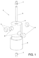
Figure 1 .- Exploded view of the device in isometric perspective. - A preferred embodiment of the device of the invention (1) is described with reference to the figures.
- In a first preferred embodiment of the invention, the device (1) is installed in internal combustion engines with an injection system.
- In this case, the device (1) is installed just after the fuel pump by means of an input connector (2) and before the injection pump where the output connector (7) is connected. Once the device (1) is connected, the fuel flows through the inside of an interior tube (3) and passes through the area in which this interior tube (3) is surrounded by a housing (4) where the magnet pairs (5) are located in bore holes (8) made in the housing (4). In order to prevent the magnetic components (5) from leaving the housing (4) and to consolidate the device (1), the housing (4) is encased in an external aluminium tube (6). The magnetic components (5) are out of phase by 90° and facing two by two with the poles opposed. The fuel flows through the internal tube (3) and passes through the area of influence of the magnetic field of the magnetic components (5) and ionises and disaggregates.
- The fuel in the internal tube (3) is subjected to the action of the magnetic components (5), causing the fuel to become ionised and disaggregates more effectively. It also causes a molecular change, giving the fuel a rotational movement at a molecular level that results in an improvement in the combustion process and an accompanying reduction in CO2 emission.
- In another embodiment of the invention, the device (1) is installed in gas burners, ovens, etc. In this case, the device (1) is installed at the entrance of the gas to the burner, as close as possible to the equipment.
- In a third embodiment of the invention, the device (1) is installed in internal combustion engines without an injection system; in this case the device (1) is installed at the entrance to the carburettor.
Claims (10)
- Device (1) for fuel saving and reducing contaminants and CO2 comprising:- a housing (4) that has at least two pairs of bore holes (8) opposed two by two, and- at least one pair of magnetic components (5) located in the bore holes (8) arranged with the central axes perpendicular to the housing (4),
characterised in that:- each pair of magnetic components (5) forms an angle with respect to another pair of magnetic components (5), with each pair of magnetic components (5) being in parallel planes, and each pair of magnetic components (5) generating a magnetic field out of phase with respect to another pair of magnetic components (5). - Device (1) for fuel saving and reducing contaminants and CO2 according to claim 1, characterised in that it additionally comprises an input connector (2) arranged coaxially to the housing (4) enabling the entrance of fuel.
- Device (1) for fuel saving and reducing contaminants and CO2 according to claim 1, characterised in that it additionally comprises an output connector (7) arranged coaxially to the housing (4) enabling the exit of fuel.
- Device (1) for fuel saving and reducing contaminants and CO2 according to claims 2 and 3, characterised in that it additionally comprises an internal tube (3) through which the fuel flows coupled by one end to the input connector (2) and by the other end to the output connector (7).
- Device (1) for fuel saving and reducing contaminants and CO2 according to claim 1, characterised in that it additionally comprises an external tube (6) encasing the assembly comprising the housing (4) and the magnetic components (5).
- Device (1) for fuel saving and reducing contaminants and CO2 according to claim 1, characterised in that the magnetic components (5) comprise: a magnet, an electromagnet or a combination of a magnet with a metallic part.
- Device (1) for fuel saving and reducing contaminants and CO2 according to claim 1, characterised in that the magnetic components (5) of each pair of magnetic components (5) are arranged with the opposite poles facing and the magnetisation axis perpendicular to the axis of the internal tube (3).
- Device (1) for fuel saving and reducing contaminants and CO2 according to claim 1, characterised in that the housing (4) comprises two parts.
- Device (1) for fuel saving and reducing contaminants and CO2 according to claim 1, characterised in that each pair of magnetic components (5) are arranged at an angle of 90° with respect to another pair of magnetic components (5).
- Device (1) for fuel saving and reducing contaminants and CO2 according to claim 1, characterised in that it additionally comprises some parts of ferromagnetic material extending from the magnetic components (5) in the bore holes (8) of the housing (4) for channelling the magnetic flows.
Priority Applications (1)
| Application Number | Priority Date | Filing Date | Title |
|---|---|---|---|
| EP09152611A EP2218898A1 (en) | 2009-02-11 | 2009-02-11 | Fuel saving device |
Applications Claiming Priority (1)
| Application Number | Priority Date | Filing Date | Title |
|---|---|---|---|
| EP09152611A EP2218898A1 (en) | 2009-02-11 | 2009-02-11 | Fuel saving device |
Publications (1)
| Publication Number | Publication Date |
|---|---|
| EP2218898A1 true EP2218898A1 (en) | 2010-08-18 |
Family
ID=40750866
Family Applications (1)
| Application Number | Title | Priority Date | Filing Date |
|---|---|---|---|
| EP09152611A Withdrawn EP2218898A1 (en) | 2009-02-11 | 2009-02-11 | Fuel saving device |
Country Status (1)
| Country | Link |
|---|---|
| EP (1) | EP2218898A1 (en) |
Cited By (3)
| Publication number | Priority date | Publication date | Assignee | Title |
|---|---|---|---|---|
| WO2013010197A1 (en) * | 2011-07-18 | 2013-01-24 | Eu-Trucktec Gmbh | Apparatus for the preparation of gaseous or liquid energy carriers |
| JP2015537152A (en) * | 2012-11-28 | 2015-12-24 | マリア ミヒャエラ バリリツ−グプタMaria Michaela Barilits−Gupta | Apparatus for magnetic treatment of fluids containing hydrocarbons |
| EP4700229A1 (en) | 2024-08-19 | 2026-02-25 | Yusuf Aberle | Emission reduction |
Citations (18)
| Publication number | Priority date | Publication date | Assignee | Title |
|---|---|---|---|---|
| ES1013801U (en) | 1990-04-11 | 1991-01-16 | Texido Serradell Magdalena | Device for improving the performance of internal combustión engines. (Machine-translation by Google Translate, not legally binding) |
| ES1014636U (en) | 1990-06-25 | 1991-04-16 | Creatividad Y Diseno, S.A. | Portable apparatus for irrigation toy. (Machine-translation by Google Translate, not legally binding) |
| ES1021455U (en) | 1992-05-29 | 1992-12-01 | Jacques Agosti, S.L. | Magnetic device for the treatment of liquid motor fuels and the like. (Machine-translation by Google Translate, not legally binding) |
| ES1021718U (en) | 1992-06-26 | 1993-01-01 | Soto Bertran Juan | Device for purifying fuel in motor vehicles. (Machine-translation by Google Translate, not legally binding) |
| ES2047849T3 (en) | 1989-04-17 | 1994-03-01 | Shinfuji Kogyo Kk | A METHOD FOR TREATING A LIQUID HYDROCARBON FUEL. |
| ES1026296U (en) | 1993-11-17 | 1994-04-01 | Rica Almazan | Fuel economizing device for boilers and engines. (Machine-translation by Google Translate, not legally binding) |
| ES2048970T3 (en) | 1989-05-26 | 1994-04-01 | Wribro Ltd | IMPROVING THE COMBUSTION PERFORMANCE OF A FUEL. |
| US5348050A (en) * | 1993-07-19 | 1994-09-20 | Ashton Thomas E | Magnetic fluid treatment device |
| DE9410122U1 (en) * | 1994-06-23 | 1994-09-22 | Olsen, Sven, 24943 Flensburg | Fuel activation device |
| ES2071176T3 (en) | 1990-08-28 | 1995-06-16 | Gekko International Inc | MAGNETIC APPARATUS FOR FUEL TREATMENT. |
| ES2099010A2 (en) | 1993-11-11 | 1997-05-01 | Felipe Ciriaco Jimenez | Fuel economizer |
| EP0852291A1 (en) * | 1997-01-06 | 1998-07-08 | Jean-Charles Henry Krings | Fuel saving device |
| ES2153051T3 (en) | 1994-10-25 | 2001-02-16 | Wenhao Wang | FUEL ECONOMIZING DEVICE. |
| ES1049045U (en) | 2001-04-18 | 2001-11-01 | Polarizador Ronser S L | Improved fuel economizer |
| ES1051258U (en) | 2002-02-18 | 2002-07-16 | Sanchis Fernando Beneyto | Fuel economizer. (Machine-translation by Google Translate, not legally binding) |
| WO2003021102A1 (en) * | 2001-09-04 | 2003-03-13 | Yugen Kaisha Plan Tec | Heat engine liquid fuel activation device |
| DE10255135A1 (en) * | 2001-12-03 | 2003-07-17 | Alfred Goetz | Automotive engine fuel delivered through cylindrical pipe feed with transverse array of permanent magnets for breaking down molecular clusters in the hydrocarbon fuel supply |
| ES2248726T3 (en) | 2002-01-29 | 2006-03-16 | AIR & D- SARL | ELIMINATION OR REDUCTION OF MALOLIENT SUBSTANCES IN THE AIR. |
-
2009
- 2009-02-11 EP EP09152611A patent/EP2218898A1/en not_active Withdrawn
Patent Citations (19)
| Publication number | Priority date | Publication date | Assignee | Title |
|---|---|---|---|---|
| ES2047849T3 (en) | 1989-04-17 | 1994-03-01 | Shinfuji Kogyo Kk | A METHOD FOR TREATING A LIQUID HYDROCARBON FUEL. |
| ES2048970T3 (en) | 1989-05-26 | 1994-04-01 | Wribro Ltd | IMPROVING THE COMBUSTION PERFORMANCE OF A FUEL. |
| ES1013801U (en) | 1990-04-11 | 1991-01-16 | Texido Serradell Magdalena | Device for improving the performance of internal combustión engines. (Machine-translation by Google Translate, not legally binding) |
| ES1014636U (en) | 1990-06-25 | 1991-04-16 | Creatividad Y Diseno, S.A. | Portable apparatus for irrigation toy. (Machine-translation by Google Translate, not legally binding) |
| ES2071176T3 (en) | 1990-08-28 | 1995-06-16 | Gekko International Inc | MAGNETIC APPARATUS FOR FUEL TREATMENT. |
| ES1021455U (en) | 1992-05-29 | 1992-12-01 | Jacques Agosti, S.L. | Magnetic device for the treatment of liquid motor fuels and the like. (Machine-translation by Google Translate, not legally binding) |
| ES1021718U (en) | 1992-06-26 | 1993-01-01 | Soto Bertran Juan | Device for purifying fuel in motor vehicles. (Machine-translation by Google Translate, not legally binding) |
| US5348050A (en) * | 1993-07-19 | 1994-09-20 | Ashton Thomas E | Magnetic fluid treatment device |
| ES2099010A2 (en) | 1993-11-11 | 1997-05-01 | Felipe Ciriaco Jimenez | Fuel economizer |
| ES1026296U (en) | 1993-11-17 | 1994-04-01 | Rica Almazan | Fuel economizing device for boilers and engines. (Machine-translation by Google Translate, not legally binding) |
| DE9410122U1 (en) * | 1994-06-23 | 1994-09-22 | Olsen, Sven, 24943 Flensburg | Fuel activation device |
| ES2153051T3 (en) | 1994-10-25 | 2001-02-16 | Wenhao Wang | FUEL ECONOMIZING DEVICE. |
| EP0852291A1 (en) * | 1997-01-06 | 1998-07-08 | Jean-Charles Henry Krings | Fuel saving device |
| ES1049045U (en) | 2001-04-18 | 2001-11-01 | Polarizador Ronser S L | Improved fuel economizer |
| ES2241855T3 (en) | 2001-04-18 | 2005-11-01 | Polarizador Ronser, S.L. | PERFECTED FUEL ECONOMIZER. |
| WO2003021102A1 (en) * | 2001-09-04 | 2003-03-13 | Yugen Kaisha Plan Tec | Heat engine liquid fuel activation device |
| DE10255135A1 (en) * | 2001-12-03 | 2003-07-17 | Alfred Goetz | Automotive engine fuel delivered through cylindrical pipe feed with transverse array of permanent magnets for breaking down molecular clusters in the hydrocarbon fuel supply |
| ES2248726T3 (en) | 2002-01-29 | 2006-03-16 | AIR & D- SARL | ELIMINATION OR REDUCTION OF MALOLIENT SUBSTANCES IN THE AIR. |
| ES1051258U (en) | 2002-02-18 | 2002-07-16 | Sanchis Fernando Beneyto | Fuel economizer. (Machine-translation by Google Translate, not legally binding) |
Cited By (3)
| Publication number | Priority date | Publication date | Assignee | Title |
|---|---|---|---|---|
| WO2013010197A1 (en) * | 2011-07-18 | 2013-01-24 | Eu-Trucktec Gmbh | Apparatus for the preparation of gaseous or liquid energy carriers |
| JP2015537152A (en) * | 2012-11-28 | 2015-12-24 | マリア ミヒャエラ バリリツ−グプタMaria Michaela Barilits−Gupta | Apparatus for magnetic treatment of fluids containing hydrocarbons |
| EP4700229A1 (en) | 2024-08-19 | 2026-02-25 | Yusuf Aberle | Emission reduction |
Similar Documents
| Publication | Publication Date | Title |
|---|---|---|
| US5664546A (en) | Fuel saving device | |
| Chaware | Review on effect of fuel magnetism by varying intensity on performance and emission of single cylinder four stroke diesel engine | |
| US9381520B2 (en) | Apparatus and method for magnetically treating fluids | |
| RU2671451C2 (en) | Device for treatment of liquid and gaseous substances containing hydrogen and carbon | |
| EP2218898A1 (en) | Fuel saving device | |
| EP0871820B1 (en) | Magnetic polarization device for treating fuel | |
| RU2082897C1 (en) | Liquid fuel magnetic activator | |
| EP1831533B1 (en) | Magnetic device for treating liquids and gases | |
| US20140099253A1 (en) | Method and apparatus for magnetic treament of fuel and fluids for combustiion efficiency and reduction of carbon emissions | |
| DK177981B1 (en) | Method and apparatus for increasing gaseous content of a hydrocarbon fuel | |
| KR20030000167A (en) | Heat engine for increasing combustibility of fuel | |
| Raut et al. | Experimental inspection by using the effect of magnetic field on the performance of diesel engine | |
| RU2613504C2 (en) | Treatment method of liquid environments with short low frequency electromagnetic pulses | |
| US20170074217A1 (en) | Fuel saver and contaminants reducer system and method | |
| RU166579U1 (en) | DEVICE FOR PREPARING A FUEL AND FUEL MIXTURE BEFORE BURNING IN A HEAT-POWER UNIT | |
| CN202117801U (en) | Magnetic treatment device | |
| RU44152U1 (en) | FUEL PROCESSING DEVICE | |
| WO2007119141A2 (en) | Polarizer apparatus for improving the combustion of liquid or gaseous fuels | |
| EP1179710A1 (en) | Fuel economiser for combustion devices | |
| RU2307258C2 (en) | Device for magnetic treatment of liquid fuel | |
| RU101034U1 (en) | MAGNETIC LIQUID TREATMENT DEVICE | |
| US20090095267A1 (en) | Magnetic apparatus comprising vanes and grooves for the treatment of supply fuels | |
| US20070071611A1 (en) | Apparatus for increasing efficiency in fluid delivery systems using magnetic fields | |
| KR20090010964U (en) | Liquid ionizer using both magnetic poles of permanent magnets | |
| RU2266427C1 (en) | Fuel corrector |
Legal Events
| Date | Code | Title | Description |
|---|---|---|---|
| PUAI | Public reference made under article 153(3) epc to a published international application that has entered the european phase |
Free format text: ORIGINAL CODE: 0009012 |
|
| AK | Designated contracting states |
Kind code of ref document: A1 Designated state(s): AT BE BG CH CY CZ DE DK EE ES FI FR GB GR HR HU IE IS IT LI LT LU LV MC MK MT NL NO PL PT RO SE SI SK TR |
|
| AX | Request for extension of the european patent |
Extension state: AL BA RS |
|
| AKY | No designation fees paid | ||
| REG | Reference to a national code |
Ref country code: DE Ref legal event code: R108 Effective date: 20110329 Ref country code: DE Ref legal event code: 8566 |
|
| STAA | Information on the status of an ep patent application or granted ep patent |
Free format text: STATUS: THE APPLICATION IS DEEMED TO BE WITHDRAWN |
|
| 18D | Application deemed to be withdrawn |
Effective date: 20110219 |