EP2218560B1 - Rotary cutter unit and printer device having the unit - Google Patents
Rotary cutter unit and printer device having the unit Download PDFInfo
- Publication number
- EP2218560B1 EP2218560B1 EP20100162651 EP10162651A EP2218560B1 EP 2218560 B1 EP2218560 B1 EP 2218560B1 EP 20100162651 EP20100162651 EP 20100162651 EP 10162651 A EP10162651 A EP 10162651A EP 2218560 B1 EP2218560 B1 EP 2218560B1
- Authority
- EP
- European Patent Office
- Prior art keywords
- rotating blade
- rotary cutter
- gear
- cutter unit
- comparative example
- Prior art date
- Legal status (The legal status is an assumption and is not a legal conclusion. Google has not performed a legal analysis and makes no representation as to the accuracy of the status listed.)
- Ceased
Links
Images



Classifications
-
- B—PERFORMING OPERATIONS; TRANSPORTING
- B41—PRINTING; LINING MACHINES; TYPEWRITERS; STAMPS
- B41J—TYPEWRITERS; SELECTIVE PRINTING MECHANISMS, i.e. MECHANISMS PRINTING OTHERWISE THAN FROM A FORME; CORRECTION OF TYPOGRAPHICAL ERRORS
- B41J11/00—Devices or arrangements of selective printing mechanisms, e.g. ink-jet printers or thermal printers, for supporting or handling copy material in sheet or web form
- B41J11/66—Applications of cutting devices
-
- B—PERFORMING OPERATIONS; TRANSPORTING
- B26—HAND CUTTING TOOLS; CUTTING; SEVERING
- B26D—CUTTING; DETAILS COMMON TO MACHINES FOR PERFORATING, PUNCHING, CUTTING-OUT, STAMPING-OUT OR SEVERING
- B26D7/00—Details of apparatus for cutting, cutting-out, stamping-out, punching, perforating, or severing by means other than cutting
- B26D7/26—Means for mounting or adjusting the cutting member; Means for adjusting the stroke of the cutting member
-
- B—PERFORMING OPERATIONS; TRANSPORTING
- B26—HAND CUTTING TOOLS; CUTTING; SEVERING
- B26D—CUTTING; DETAILS COMMON TO MACHINES FOR PERFORATING, PUNCHING, CUTTING-OUT, STAMPING-OUT OR SEVERING
- B26D1/00—Cutting through work characterised by the nature or movement of the cutting member or particular materials not otherwise provided for; Apparatus or machines therefor; Cutting members therefor
-
- B—PERFORMING OPERATIONS; TRANSPORTING
- B26—HAND CUTTING TOOLS; CUTTING; SEVERING
- B26D—CUTTING; DETAILS COMMON TO MACHINES FOR PERFORATING, PUNCHING, CUTTING-OUT, STAMPING-OUT OR SEVERING
- B26D1/00—Cutting through work characterised by the nature or movement of the cutting member or particular materials not otherwise provided for; Apparatus or machines therefor; Cutting members therefor
- B26D1/01—Cutting through work characterised by the nature or movement of the cutting member or particular materials not otherwise provided for; Apparatus or machines therefor; Cutting members therefor involving a cutting member which does not travel with the work
- B26D1/12—Cutting through work characterised by the nature or movement of the cutting member or particular materials not otherwise provided for; Apparatus or machines therefor; Cutting members therefor involving a cutting member which does not travel with the work having a cutting member moving about an axis
-
- B—PERFORMING OPERATIONS; TRANSPORTING
- B26—HAND CUTTING TOOLS; CUTTING; SEVERING
- B26D—CUTTING; DETAILS COMMON TO MACHINES FOR PERFORATING, PUNCHING, CUTTING-OUT, STAMPING-OUT OR SEVERING
- B26D1/00—Cutting through work characterised by the nature or movement of the cutting member or particular materials not otherwise provided for; Apparatus or machines therefor; Cutting members therefor
- B26D1/01—Cutting through work characterised by the nature or movement of the cutting member or particular materials not otherwise provided for; Apparatus or machines therefor; Cutting members therefor involving a cutting member which does not travel with the work
- B26D1/12—Cutting through work characterised by the nature or movement of the cutting member or particular materials not otherwise provided for; Apparatus or machines therefor; Cutting members therefor involving a cutting member which does not travel with the work having a cutting member moving about an axis
- B26D1/25—Cutting through work characterised by the nature or movement of the cutting member or particular materials not otherwise provided for; Apparatus or machines therefor; Cutting members therefor involving a cutting member which does not travel with the work having a cutting member moving about an axis with a non-circular cutting member
- B26D1/34—Cutting through work characterised by the nature or movement of the cutting member or particular materials not otherwise provided for; Apparatus or machines therefor; Cutting members therefor involving a cutting member which does not travel with the work having a cutting member moving about an axis with a non-circular cutting member moving about an axis parallel to the line of cut
- B26D1/38—Cutting through work characterised by the nature or movement of the cutting member or particular materials not otherwise provided for; Apparatus or machines therefor; Cutting members therefor involving a cutting member which does not travel with the work having a cutting member moving about an axis with a non-circular cutting member moving about an axis parallel to the line of cut and coacting with a fixed blade or other fixed member
- B26D1/385—Cutting through work characterised by the nature or movement of the cutting member or particular materials not otherwise provided for; Apparatus or machines therefor; Cutting members therefor involving a cutting member which does not travel with the work having a cutting member moving about an axis with a non-circular cutting member moving about an axis parallel to the line of cut and coacting with a fixed blade or other fixed member for thin material, e.g. for sheets, strips or the like
-
- B—PERFORMING OPERATIONS; TRANSPORTING
- B26—HAND CUTTING TOOLS; CUTTING; SEVERING
- B26D—CUTTING; DETAILS COMMON TO MACHINES FOR PERFORATING, PUNCHING, CUTTING-OUT, STAMPING-OUT OR SEVERING
- B26D5/00—Arrangements for operating and controlling machines or devices for cutting, cutting-out, stamping-out, punching, perforating, or severing by means other than cutting
- B26D5/02—Means for moving the cutting member into its operative position for cutting
-
- B—PERFORMING OPERATIONS; TRANSPORTING
- B26—HAND CUTTING TOOLS; CUTTING; SEVERING
- B26D—CUTTING; DETAILS COMMON TO MACHINES FOR PERFORATING, PUNCHING, CUTTING-OUT, STAMPING-OUT OR SEVERING
- B26D5/00—Arrangements for operating and controlling machines or devices for cutting, cutting-out, stamping-out, punching, perforating, or severing by means other than cutting
-
- B—PERFORMING OPERATIONS; TRANSPORTING
- B26—HAND CUTTING TOOLS; CUTTING; SEVERING
- B26D—CUTTING; DETAILS COMMON TO MACHINES FOR PERFORATING, PUNCHING, CUTTING-OUT, STAMPING-OUT OR SEVERING
- B26D5/00—Arrangements for operating and controlling machines or devices for cutting, cutting-out, stamping-out, punching, perforating, or severing by means other than cutting
- B26D5/20—Arrangements for operating and controlling machines or devices for cutting, cutting-out, stamping-out, punching, perforating, or severing by means other than cutting with interrelated action between the cutting member and work feed
-
- Y—GENERAL TAGGING OF NEW TECHNOLOGICAL DEVELOPMENTS; GENERAL TAGGING OF CROSS-SECTIONAL TECHNOLOGIES SPANNING OVER SEVERAL SECTIONS OF THE IPC; TECHNICAL SUBJECTS COVERED BY FORMER USPC CROSS-REFERENCE ART COLLECTIONS [XRACs] AND DIGESTS
- Y10—TECHNICAL SUBJECTS COVERED BY FORMER USPC
- Y10T—TECHNICAL SUBJECTS COVERED BY FORMER US CLASSIFICATION
- Y10T83/00—Cutting
- Y10T83/141—With means to monitor and control operation [e.g., self-regulating means]
- Y10T83/148—Including means to correct the sensed operation
-
- Y—GENERAL TAGGING OF NEW TECHNOLOGICAL DEVELOPMENTS; GENERAL TAGGING OF CROSS-SECTIONAL TECHNOLOGIES SPANNING OVER SEVERAL SECTIONS OF THE IPC; TECHNICAL SUBJECTS COVERED BY FORMER USPC CROSS-REFERENCE ART COLLECTIONS [XRACs] AND DIGESTS
- Y10—TECHNICAL SUBJECTS COVERED BY FORMER USPC
- Y10T—TECHNICAL SUBJECTS COVERED BY FORMER US CLASSIFICATION
- Y10T83/00—Cutting
- Y10T83/465—Cutting motion of tool has component in direction of moving work
- Y10T83/4766—Orbital motion of cutting blade
- Y10T83/4795—Rotary tool
- Y10T83/483—With cooperating rotary cutter or backup
-
- Y—GENERAL TAGGING OF NEW TECHNOLOGICAL DEVELOPMENTS; GENERAL TAGGING OF CROSS-SECTIONAL TECHNOLOGIES SPANNING OVER SEVERAL SECTIONS OF THE IPC; TECHNICAL SUBJECTS COVERED BY FORMER USPC CROSS-REFERENCE ART COLLECTIONS [XRACs] AND DIGESTS
- Y10—TECHNICAL SUBJECTS COVERED BY FORMER USPC
- Y10T—TECHNICAL SUBJECTS COVERED BY FORMER US CLASSIFICATION
- Y10T83/00—Cutting
- Y10T83/465—Cutting motion of tool has component in direction of moving work
- Y10T83/4766—Orbital motion of cutting blade
- Y10T83/4795—Rotary tool
- Y10T83/483—With cooperating rotary cutter or backup
- Y10T83/4838—With anvil backup
-
- Y—GENERAL TAGGING OF NEW TECHNOLOGICAL DEVELOPMENTS; GENERAL TAGGING OF CROSS-SECTIONAL TECHNOLOGIES SPANNING OVER SEVERAL SECTIONS OF THE IPC; TECHNICAL SUBJECTS COVERED BY FORMER USPC CROSS-REFERENCE ART COLLECTIONS [XRACs] AND DIGESTS
- Y10—TECHNICAL SUBJECTS COVERED BY FORMER USPC
- Y10T—TECHNICAL SUBJECTS COVERED BY FORMER US CLASSIFICATION
- Y10T83/00—Cutting
- Y10T83/869—Means to drive or to guide tool
- Y10T83/8798—With simple oscillating motion only
- Y10T83/8817—Axially entending cutting edge
Definitions
- the present invention relates to a rotary cutter unit having a mechanism for detecting a waiting position of the unit, and a printer device having the rotary cutter unit.
- a cutter having a V-shaped blade or a spiral blade is provided for cutting printing paper after printing.
- a rotary cutter having a spiral blade formed on a cylindrical rotating body, is arranged in a printer, the printer may be more compact than a printer having another type of cutter such as the V-shaped cutter.
- 2-167696 discloses a control device for cutting a sheet, having a detecting member 9 attached to the side of a knife rotor 4 and a detection sensor 10 capable of transmitting a stop command when detecting member 9 is positioned where the detecting member cannot be detected during deceleration, so that knife 8 does not stop at a position where the knife can cut a sheet.
- Japanese Examined Utility Model Publication (Kokoku) No. 7-1272 discloses a rotary cutter device, in which a disk 5 having a notch 5a formed thereon is attached to a rotation shaft of a rotating blade 1 and a photosensor 6 detects the position of notch 5a, whereby rotating blade 1 may be stopped at a rotational position within a predetermined range.
- disk 5 and photosensor 6 for detecting the rotational position of rotating blade 1 are arranged outside of rotating blade 1 in relation to the axial direction of the rotating blade, and therefore the printer inevitably has a wide width due to the volumes of disk 5a and photosensor 6.
- US 5,000,069 describes a paper cutter.
- the paper cutter has a cutter bar and rotary cutting blade that cooperate to slit a continuous web of paper passing therethrough across the entire width thereof.
- a cam is provided on one end of the cutter roll which lifts the cutter bar out of operative contact with the cutter roll and blade for a portion of a revolution of the cutter roll.
- the cutter bar is spring-urged into contact with the cutter roll and the cutter roll is axially shifted along the cutter bar to move the cam and into and out of contact with the cutter bar to selectively disable the slitting of the paper web for a small portion of the width thereof to allow discreet individual portions of the web to remain connected together for further operations at another location.
- the cutter roll is driven by a motor, and is axially shifted by solenoid lever arrangement to position it relative to the cutter bar.
- an object of the present invention is to provide a rotary cutter unit having a compact mechanism for detecting the home position thereof, and a printer device having the rotary cutter unit.
- a rotary cutter unit according to claim 1.
- the rotating blade has a gear for driving the rotating blade at one end portion thereof, and the detected part is a fin-shaped member formed on a shaft portion of the gear.
- a printer device comprising the rotary cutter unit of the invention.
- Fig. 1a is a perspective view of a thermal printer device 10 according to a preferable embodiment of the invention.
- Thermal printer 10 has a main frame 12 and a head module 14 configured to detachably attached to main frame 12, as shown in Fig. 2a .
- a platen roller (hereinafter, referred to as "platen") 16 having a rubber roller is contained in main frame 12, and platen 16 is rotatably driven by a pulse motor (not shown). Output power of the pulse motor is transmitted to platen 16 via a first pulley 18 (see Fig. 2b ) coupled to an output shaft of the pulse motor, a first timing belt 20, and a second pulley 24 attached to a first shaft portion 22 of platen 16.
- a rotating blade 26 of a rotary cutter unit for cutting printing paper (not shown) is contained in main frame 12, and rotating blade 26 is rotatably driven about a center axis L by means of a pulse motor (not shown).
- Output power of the pulse motor is transmitted to rotating blade 26 via a third pulley 28 coupled to an output shaft of the pulse motor, a second timing belt 30, a fourth pulley 34 attached to a second shaft portion 32 of platen 16, a first gear 36 formed integrally with fourth pulley 34, and a second gear 38 engaged with first gear 36.
- Rotating blade 26 can cut printing paper (not shown) in cooperation with a fixed blade 40 (as shown in Fig. 2b ) fixed to head module 14.
- an application of the rotary cutter unit of the present invention is not limited to such a printer device having a module-type thermal head.
- Fig. 3 is an enlarged view of a part "A" of Fig. 2a showing a first comparative example of a rotary cutter unit.
- a fin-shaped detected member 44 radially outwardly extending from an end portion 42 opposed to second gear 38 of rotating blade 26, is arranged.
- a detecting part or a photosensor 46 is arranged for detecting fin-shaped member 44 when rotating blade 26 is positioned at "a home position" ( Fig. 3 ).
- photosensor 46 is a transmissive-type photosensor having an U-shaped recess, configured so that detected member 44 is positioned in the recess when the rotating blade is at the home position.
- fin-shaped member 44 and photosensor 46 are not positioned outside (in Fig.
- the width of main frame 12 is not increased due to the volumes of fin-shaped member 44 and photosensor 46, whereby the printer device may be compact.
- Fig. 4 shows a modification of the constitution of Fig. 3 .
- the constitution of Fig. 4 is different from that of Fig. 3 in that photosensor 46 is positioned above rotating blade 26. As shown in Fig. 4 , it is not necessary to position photosensor 46 at the lower part of main frame 12. In other words, the position of photosensor may be properly determined in view of the location of the other components within the main frame.
- Fig. 5 shows a second comparative example of the rotary cutter unit.
- a mark 48 as a detected part is arranged on the lateral side of rotating blade 26, instead of fin-shaped member 44 of the first embodiment.
- the second comparative example uses a reflective-type photosensor 50 instead of transmissive photosensor 46 of the first comparative example.
- mark 48 is a mark having an arbitrary shape such as a line, a circle or a polygon, the color of which (for example, black or dark color) is different from the color of a part of the side of rotating blade 26 other than the mark.
- Reflective photosensor 50 is positioned at a place where the photosensor can detect mark 48 when rotating blade 26 is positioned at the home position.
- mark 48 When photosensor 50 faces mark 48, a light from the photosensor and reflected by the mark is weak in comparison to when photosensor 50 faces a part of rotating blade (generally having metallic or light color) other than the mark, whereby the photosensor may detect whether rotating blade 26 is positioned at the home position or not.
- mark 48 has not the volume substantially and reflective photosensor 50 is not positioned outside of end portion 42 of rotating blade 26. Therefore, the printer device may be compact.
- Fig. 6 shows a third comparative example of the rotary cutter unit.
- photosensor 46 of the first comparative example is replaced with a mechanical switch 52.
- Mechanical switch 52 has a body 54 and a knob 56 pivotably mounted on body 54.
- Knob 54 is upwardly biased and configured to be pushed down by contacting fin-shaped member 44 formed on end portion 42 of rotating blade 26.
- Fig. 7 shows a fourth comparative example of the rotary cutter unit.
- rotating blade 26 a part of which is removed, is used as the detected part, instead of the fin-shaped member.
- a part of end portion 42 of rotating blade 26 is removed or cut off, so as to form a generally D-shaped portion viewed in the axial direction of the rotating blade.
- Mechanical switch 52 is arranged so that knob 56 is pushed down by an arc 58 of the D-shaped portion as shown in Fig. 8a , and knob 56 is not pushed down by a chord 60 of the D-shaped portion as shown in Fig. 8b .
- a mechanism for detecting the waiting position or the home position of rotating blade 26 is positioned near end portion 42 opposed to second gear 38 fixed to the rotating blade.
- the mechanism for detection may be positioned near second gear 38.
- a fin-shaped detected member 64 similar to fin-shaped member 44 of the first embodiment, is arranged on a gear shaft 62 of rotating blade 26.
- gear shaft 62 is positioned inside relative to second gear 38 in the direction of the rotational axis of rotating blade 26.
- a transmissive-type photosensor 66 similar to transmissive photosensor 46 of the first comparative example, is arranged for detecting detected member 64. Since the thickness (or the dimension in the axial direction of rotating blade 26) of fin-shaped member 64 may be small, it is not necessary to increase the length of gear shaft 62 due to the presence of member 64 on gear shaft 62. Therefore, the printer device may be compact.
- Fig. 10 shows a fifth comparative example of the rotary cutter unit, similar to the third comparative example as shown in Fig. 3 .
- photosensor 66 of the embodiment is replaced with a mechanical switch 68.
- Mechanical switch 68 has a body 70 and a knob 72 pivotably mounted on body 70. Knob 72 is upwardly biased and configured to be pushed down by contacting fin-shaped member 64 formed on gear shaft 62 of rotating blade 26. By arranging mechanical switch 68 at a position where knob 72 of switch 68 is pushed down by fin-shaped member 64 when rotating blade 26 is positioned at the home position, it can be detected as to whether rotating blade 26 is positioned at the home position or not.
- Fig. 11 shows a sixth comparative example of the rotary cutter unit.
- a mechanical switch 68 similar to mechanical switch 52 of the third comparative example is used, a disk 74 fixed to gear shaft 62 is used as the detected part, instead of the fin-shaped member.
- disk 74 is a circular disk, a part of which is removed or cut off, so as to form a generally D-shaped thin plate.
- the sixth comparative example uses a feature generally the same as the fourth comparative example of Fig. 8 .
- mechanical switch 68 is arranged so that knob 72 of the switch is pushed down by an arc of the D-shaped plate, and knob 72 is not pushed down by a chord of the D-shaped plate.
- a gear is provided to the rotating blade to rotate or drive the rotating blade, the detected part is positioned on a gear shaft of the gear, therefore the printer device may be compact.
Landscapes
- Life Sciences & Earth Sciences (AREA)
- Forests & Forestry (AREA)
- Engineering & Computer Science (AREA)
- Mechanical Engineering (AREA)
- Handling Of Sheets (AREA)
Description
- The present invention relates to a rotary cutter unit having a mechanism for detecting a waiting position of the unit, and a printer device having the rotary cutter unit.
- In a conventional printer, printing paper unwound from a roll of paper is nipped between a platen roller and a thermal head, and printing is carried out by heating the thermal head during the feeding of the paper. In some printers, a cutter having a V-shaped blade or a spiral blade is provided for cutting printing paper after printing. When a rotary cutter, having a spiral blade formed on a cylindrical rotating body, is arranged in a printer, the printer may be more compact than a printer having another type of cutter such as the V-shaped cutter. For example, Japanese Unexamined Patent Publication (Kokai) No.
2-167696 detection sensor 10 capable of transmitting a stop command when detecting member 9 is positioned where the detecting member cannot be detected during deceleration, so that knife 8 does not stop at a position where the knife can cut a sheet. - Japanese Examined Utility Model Publication (Kokoku) No.
7-1272 - In a rotary cutter having a fixed blade and a rotating blade, when the blades contact each other or are positioned close to each other, it is difficult to smoothly insert printing paper between the blades, which may result in a paper jam. Therefore, when the rotating blade is stopped, it is necessary to control the stopping position of the rotating blade so that an edge of the rotating blade is away from the fixed blade by a certain distance (in other words, the rotating blade is positioned at a waiting position, a so-called "a home position"). In both Japanese Unexamined Patent Publication (Kokai) No.
2-167696 7-1272 - For example, in the printer of Japanese Examined Utility Model Publication (Kokoku) No.
7-1272 -
US 5,000,069 describes a paper cutter. The paper cutter has a cutter bar and rotary cutting blade that cooperate to slit a continuous web of paper passing therethrough across the entire width thereof. A cam is provided on one end of the cutter roll which lifts the cutter bar out of operative contact with the cutter roll and blade for a portion of a revolution of the cutter roll. The cutter bar is spring-urged into contact with the cutter roll and the cutter roll is axially shifted along the cutter bar to move the cam and into and out of contact with the cutter bar to selectively disable the slitting of the paper web for a small portion of the width thereof to allow discreet individual portions of the web to remain connected together for further operations at another location. The cutter roll is driven by a motor, and is axially shifted by solenoid lever arrangement to position it relative to the cutter bar. - Accordingly, an object of the present invention is to provide a rotary cutter unit having a compact mechanism for detecting the home position thereof, and a printer device having the rotary cutter unit.
- According to one aspect of the present invention, there is provided a rotary cutter unit according to claim 1.
- According to the invention the rotating blade has a gear for driving the rotating blade at one end portion thereof, and the detected part is a fin-shaped member formed on a shaft portion of the gear.
- According to another aspect of the present invention, there may be provided a printer device comprising the rotary cutter unit of the invention.
- The above and other objects, features and advantages of the present invention will be made more apparent by the following description of the preferred embodiments thereof, with reference to the accompanying drawings, wherein:
-
Fig. 1a is a perspective view of a printer device having a rotary cutter unit of the invention when a head module thereof is assembled; -
Fig. 1b is a side view viewed in the direction of anarrow 1 b ofFig. 1a ; -
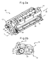
Fig. 2a is a perspective view of the printer device having the rotary cutter unit of the invention when the head module thereof is detached; -
Fig. 2b is a side view viewed in the direction of anarrow 2b ofFig. 2a ; -
Fig. 3 is an enlarged view of a rotary cutter unit according to a first comparative example; -
Fig. 4 is an enlarged view of a modification of the rotary cutter unit according to the first comparative example; -
Fig. 5 is an enlarged view of a rotary cutter unit according to a second comparative example; -
Fig. 6 is an enlarged view of a rotary cutter unit according to a third comparative example; -
Fig. 7 is an enlarged view of a rotary cutter unit according to a fourth comparative example; -
Fig. 8a is a schematic side view of the fourth comparative example in which an arc portion of a rotating blade contacts a knob of a mechanical switch; -
Fig. 8b is a schematic side view of the fourth comparative example in which a chord portion of a rotating blade contacts or is adjacent to a knob of a mechanical switch; -
Fig. 9 is an enlarged view of a rotary cutter unit according to an embodiment of the invention; -
Fig. 10 is an enlarged view of a rotary cutter unit according to a fifth comparative example; and -
Fig. 11 is an enlarged view of a rotary cutter unit according to a sixth comparative example. -
Fig. 1a is a perspective view of athermal printer device 10 according to a preferable embodiment of the invention.Thermal printer 10 has amain frame 12 and ahead module 14 configured to detachably attached tomain frame 12, as shown inFig. 2a . A platen roller (hereinafter, referred to as "platen") 16 having a rubber roller is contained inmain frame 12, andplaten 16 is rotatably driven by a pulse motor (not shown). Output power of the pulse motor is transmitted toplaten 16 via a first pulley 18 (seeFig. 2b ) coupled to an output shaft of the pulse motor, afirst timing belt 20, and asecond pulley 24 attached to a first shaft portion 22 ofplaten 16. - As shown in
Fig. 2a , a rotatingblade 26 of a rotary cutter unit for cutting printing paper (not shown) is contained inmain frame 12, and rotatingblade 26 is rotatably driven about a center axis L by means of a pulse motor (not shown). Output power of the pulse motor is transmitted to rotatingblade 26 via athird pulley 28 coupled to an output shaft of the pulse motor, asecond timing belt 30, afourth pulley 34 attached to asecond shaft portion 32 ofplaten 16, afirst gear 36 formed integrally withfourth pulley 34, and asecond gear 38 engaged withfirst gear 36. Rotatingblade 26 can cut printing paper (not shown) in cooperation with a fixed blade 40 (as shown inFig. 2b ) fixed tohead module 14. However, an application of the rotary cutter unit of the present invention is not limited to such a printer device having a module-type thermal head. -
Fig. 3 is an enlarged view of a part "A" ofFig. 2a showing a first comparative example of a rotary cutter unit. A fin-shaped detectedmember 44, radially outwardly extending from anend portion 42 opposed tosecond gear 38 ofrotating blade 26, is arranged. Withinmain frame 12, a detecting part or aphotosensor 46 is arranged for detecting fin-shapedmember 44 when rotatingblade 26 is positioned at "a home position" (Fig. 3 ). In particular,photosensor 46 is a transmissive-type photosensor having an U-shaped recess, configured so that detectedmember 44 is positioned in the recess when the rotating blade is at the home position. As shown, fin-shapedmember 44 andphotosensor 46 are not positioned outside (inFig. 3 , the right side) ofend portion 42 of rotating 26 in relation to the direction of the rotational axis (or the center axis) L of the rotating member. Therefore, the width ofmain frame 12 is not increased due to the volumes of fin-shapedmember 44 andphotosensor 46, whereby the printer device may be compact. -
Fig. 4 shows a modification of the constitution ofFig. 3 . The constitution ofFig. 4 is different from that ofFig. 3 in thatphotosensor 46 is positioned above rotatingblade 26. As shown inFig. 4 , it is not necessary to positionphotosensor 46 at the lower part ofmain frame 12. In other words, the position of photosensor may be properly determined in view of the location of the other components within the main frame. -
Fig. 5 shows a second comparative example of the rotary cutter unit. Amark 48 as a detected part is arranged on the lateral side ofrotating blade 26, instead of fin-shapedmember 44 of the first embodiment. Further, the second comparative example uses a reflective-type photosensor 50 instead oftransmissive photosensor 46 of the first comparative example. In particular,mark 48 is a mark having an arbitrary shape such as a line, a circle or a polygon, the color of which (for example, black or dark color) is different from the color of a part of the side ofrotating blade 26 other than the mark.Reflective photosensor 50 is positioned at a place where the photosensor can detectmark 48 when rotatingblade 26 is positioned at the home position. When photosensor 50 facesmark 48, a light from the photosensor and reflected by the mark is weak in comparison to whenphotosensor 50 faces a part of rotating blade (generally having metallic or light color) other than the mark, whereby the photosensor may detect whetherrotating blade 26 is positioned at the home position or not. In the second comparative example,mark 48 has not the volume substantially andreflective photosensor 50 is not positioned outside ofend portion 42 ofrotating blade 26. Therefore, the printer device may be compact. -
Fig. 6 shows a third comparative example of the rotary cutter unit. In the third comparative example, photosensor 46 of the first comparative example is replaced with amechanical switch 52.Mechanical switch 52 has abody 54 and aknob 56 pivotably mounted onbody 54.Knob 54 is upwardly biased and configured to be pushed down by contacting fin-shapedmember 44 formed onend portion 42 ofrotating blade 26. By arrangingmechanical switch 52 at a position whereknob 56 ofswitch 52 is pushed down by fin-shapedmember 44 when rotatingblade 26 is positioned at the home position, it can be detected as to whetherrotating blade 26 is positioned at the home position or not. -
Fig. 7 shows a fourth comparative example of the rotary cutter unit. In the fourth comparative example, although a mechanical switch similar tomechanical switch 52 of the third embodiment is used, rotatingblade 26, a part of which is removed, is used as the detected part, instead of the fin-shaped member. In particular, a part ofend portion 42 ofrotating blade 26 is removed or cut off, so as to form a generally D-shaped portion viewed in the axial direction of the rotating blade.Mechanical switch 52 is arranged so thatknob 56 is pushed down by anarc 58 of the D-shaped portion as shown inFig. 8a , andknob 56 is not pushed down by achord 60 of the D-shaped portion as shown inFig. 8b . By arrangingrotating blade 26 andmechanical switch 52 so that the positional relationship as shown inFig. 8b is realized when rotatingblade 26 is positioned at the home position, it can be detected as to whetherrotating blade 26 is positioned at the home position or not. - In the comparative examples as shown in
Figs. 3 to 8b , a mechanism for detecting the waiting position or the home position ofrotating blade 26 is positioned nearend portion 42 opposed tosecond gear 38 fixed to the rotating blade. However, as shown inFigs. 9 to 11 below, the mechanism for detection may be positioned nearsecond gear 38. First, in an embodiment as shown inFig. 9 , a fin-shaped detectedmember 64, similar to fin-shapedmember 44 of the first embodiment, is arranged on agear shaft 62 ofrotating blade 26. As shown,gear shaft 62 is positioned inside relative tosecond gear 38 in the direction of the rotational axis ofrotating blade 26. Further, a transmissive-type photosensor 66, similar totransmissive photosensor 46 of the first comparative example, is arranged for detecting detectedmember 64. Since the thickness (or the dimension in the axial direction of rotating blade 26) of fin-shapedmember 64 may be small, it is not necessary to increase the length ofgear shaft 62 due to the presence ofmember 64 ongear shaft 62. Therefore, the printer device may be compact. -
Fig. 10 shows a fifth comparative example of the rotary cutter unit, similar to the third comparative example as shown inFig. 3 . In the fifth comparative example, photosensor 66 of the embodiment is replaced with amechanical switch 68.Mechanical switch 68 has abody 70 and aknob 72 pivotably mounted onbody 70.Knob 72 is upwardly biased and configured to be pushed down by contacting fin-shapedmember 64 formed ongear shaft 62 ofrotating blade 26. By arrangingmechanical switch 68 at a position whereknob 72 ofswitch 68 is pushed down by fin-shapedmember 64 when rotatingblade 26 is positioned at the home position, it can be detected as to whetherrotating blade 26 is positioned at the home position or not. -
Fig. 11 shows a sixth comparative example of the rotary cutter unit. Although amechanical switch 68 similar tomechanical switch 52 of the third comparative example is used, adisk 74 fixed to gearshaft 62 is used as the detected part, instead of the fin-shaped member. In particular,disk 74 is a circular disk, a part of which is removed or cut off, so as to form a generally D-shaped thin plate. The sixth comparative example uses a feature generally the same as the fourth comparative example ofFig. 8 . In other words,mechanical switch 68 is arranged so thatknob 72 of the switch is pushed down by an arc of the D-shaped plate, andknob 72 is not pushed down by a chord of the D-shaped plate. By arrangingrotating blade 26 andmechanical switch 68 so that the chord the D-shaped portion is positioned close toknob 72 when rotatingblade 26 is positioned at the home position, it can be detected as to whetherrotating blade 26 is positioned at the home position or not. - A gear is provided to the rotating blade to rotate or drive the rotating blade, the detected part is positioned on a gear shaft of the gear, therefore the printer device may be compact.
Claims (3)
- A rotary cutter unit comprising:a rotating blade (26) having a cylindrical body configured to rotate about a center axis (L) and an edge formed on the cylindrical body, the rotating blade (26) having a gear (38) adapted to drive the rotating blade (26) at one end portion thereof;a detected part (64) formed on a shaft portion (62) of the gear (38); anda detecting part (66) for detecting the detected part (64),characterized in that the detecting part is a transmissive photosensor (66) adapted to detect the detected part (64), and the detected part is a fin-shaped member (64) radially outwardly extending from the shaft portion (62) of the gear (38).
- A printer device comprising a rotary cutter unit according to claim 1.
- The printer device according to claim 2, characterized in that the gear (38) of the rotating blade (26) is engaged with a gear (36) which is integrally formed with a platen roller (16).
Applications Claiming Priority (2)
| Application Number | Priority Date | Filing Date | Title |
|---|---|---|---|
| JP2007323458A JP5106080B2 (en) | 2007-12-14 | 2007-12-14 | Rotary cutter device and printer device provided with the rotary cutter device |
| EP20080105901 EP2070667B1 (en) | 2007-12-14 | 2008-12-01 | Rotary cutter unit and printer device having the unit |
Related Parent Applications (2)
| Application Number | Title | Priority Date | Filing Date |
|---|---|---|---|
| EP20080105901 Division-Into EP2070667B1 (en) | 2007-12-14 | 2008-12-01 | Rotary cutter unit and printer device having the unit |
| EP08105901.6 Division | 2008-12-01 |
Publications (3)
| Publication Number | Publication Date |
|---|---|
| EP2218560A2 EP2218560A2 (en) | 2010-08-18 |
| EP2218560A3 EP2218560A3 (en) | 2011-06-29 |
| EP2218560B1 true EP2218560B1 (en) | 2013-05-15 |
Family
ID=40373531
Family Applications (2)
| Application Number | Title | Priority Date | Filing Date |
|---|---|---|---|
| EP20100162651 Ceased EP2218560B1 (en) | 2007-12-14 | 2008-12-01 | Rotary cutter unit and printer device having the unit |
| EP20080105901 Ceased EP2070667B1 (en) | 2007-12-14 | 2008-12-01 | Rotary cutter unit and printer device having the unit |
Family Applications After (1)
| Application Number | Title | Priority Date | Filing Date |
|---|---|---|---|
| EP20080105901 Ceased EP2070667B1 (en) | 2007-12-14 | 2008-12-01 | Rotary cutter unit and printer device having the unit |
Country Status (5)
| Country | Link |
|---|---|
| US (2) | US9032850B2 (en) |
| EP (2) | EP2218560B1 (en) |
| JP (1) | JP5106080B2 (en) |
| KR (1) | KR101121129B1 (en) |
| CN (1) | CN101456300B (en) |
Families Citing this family (16)
| Publication number | Priority date | Publication date | Assignee | Title |
|---|---|---|---|---|
| US20100286818A1 (en) * | 2009-05-08 | 2010-11-11 | Georgia-Pacific Consumer Products Lp | Sheet product dispenser with sensor for sheet separation |
| CN104859316B (en) * | 2014-02-20 | 2017-06-13 | 东芝泰格有限公司 | Disk cutter sweep |
| JP2015174161A (en) * | 2014-03-13 | 2015-10-05 | 富士通コンポーネント株式会社 | CUTTING DEVICE, PRINTER DEVICE, AND CUTTING DEVICE CONTROL METHOD |
| ES2709024T3 (en) * | 2015-05-19 | 2019-04-12 | Aps Trading Ood | Compact platen roller movement system for thermal printing mechanism |
| US12150599B2 (en) | 2015-06-04 | 2024-11-26 | Kimberly-Clark Worldwide, Inc. | Dispenser for rolled sheet materials with motorized spindle |
| US11344165B2 (en) | 2015-06-04 | 2022-05-31 | Kimberly-Clark Worldwide, Inc. | Dispenser for rolled sheet materials with cutting system |
| US11109722B2 (en) | 2015-06-04 | 2021-09-07 | Charles Agnew Osborne, Jr. | Dispenser for rolled sheet materials |
| US12029355B2 (en) | 2015-06-04 | 2024-07-09 | Kimberly-Clark Worldwide, Inc. | Dispenser for rolled sheet materials with motorized spindle |
| EP3448640B1 (en) | 2016-04-26 | 2024-07-24 | Hewlett-Packard Development Company, L.P. | Cutting modules |
| US12358750B2 (en) | 2016-12-20 | 2025-07-15 | Charles Agnew Osborne, Jr. | Cutting system for a dispenser |
| EP3579732B1 (en) | 2017-03-17 | 2025-02-12 | Kimberly-Clark Worldwide, Inc. | Monitoring system for dispenser |
| CN111065500B (en) * | 2017-07-28 | 2022-06-14 | 克里卡特股份有限公司 | Part of a cutting apparatus of a manufacturing installation |
| US12268341B2 (en) | 2018-05-24 | 2025-04-08 | Charles Agnew Osborne, Jr. | Sheet material dispensing assembly with integrated gear clutch |
| WO2019226668A1 (en) | 2018-05-24 | 2019-11-28 | Osborne Charles Agnew Jr | Dispenser for rolled sheet materials |
| US11154166B2 (en) | 2018-05-24 | 2021-10-26 | Charles Agnew Osborne, Jr. | Dispenser for rolled sheet materials |
| EP3774363B1 (en) * | 2018-07-02 | 2025-11-19 | Hewlett-Packard Development Company, L.P. | Cutter module and method |
Family Cites Families (28)
| Publication number | Priority date | Publication date | Assignee | Title |
|---|---|---|---|---|
| US2432497A (en) * | 1945-10-04 | 1947-12-16 | Samuel M Langston Co | Cutoff mechanism |
| US3925786A (en) * | 1971-10-11 | 1975-12-09 | Bruker Physik Ag | Recorder with cutting mechanism |
| JPS51122882A (en) * | 1975-04-21 | 1976-10-27 | Hitachi Metals Ltd | Paper cutter control |
| GB1592857A (en) * | 1976-12-22 | 1981-07-08 | Stewart & Sons Hacklemakers | Cutting device |
| US4297930A (en) * | 1979-09-04 | 1981-11-03 | Cx Corporation | Strip cutter having rotatable cutting blade and strip deflecting means |
| JPS6032593B2 (en) * | 1980-05-28 | 1985-07-29 | 株式会社サト− | Printing machine web cutting device |
| JPS615593U (en) * | 1984-06-14 | 1986-01-14 | 三菱電機株式会社 | cutter drive device |
| JPS615593A (en) | 1984-06-20 | 1986-01-11 | Hitachi Ltd | Light emission electronic device and its manufacture |
| DE8716108U1 (en) * | 1987-12-05 | 1988-02-18 | Hengstler GmbH, 7209 Aldingen | Cutting device for data strips for machine output |
| JPH0688237B2 (en) | 1988-12-21 | 1994-11-09 | 新王子製紙株式会社 | Control device for stopping the sheet cutter |
| DE3918662A1 (en) * | 1989-06-08 | 1990-12-13 | Hengstler Gmbh | CUTTING DEVICE FOR MATERIAL STRIPS, LIKE PAPER OR FILM TAPE IN MACHINE DISPENSER WITH ELECTROMECHANICAL DRIVE |
| US5000069A (en) * | 1989-10-06 | 1991-03-19 | Ithaca Peripheral Inc. | Rotary cutter |
| JP2867643B2 (en) * | 1990-07-05 | 1999-03-08 | 株式会社リコー | Facsimile cutter control method |
| JPH071272A (en) | 1993-06-11 | 1995-01-06 | Okuma Mach Works Ltd | Tool magazine indexing device |
| US6145423A (en) * | 1995-09-15 | 2000-11-14 | Moore Business Forms, Inc. | Semi-automatic dispenser for linerless labels |
| JP2000501999A (en) * | 1995-12-18 | 2000-02-22 | ワシュー パトリック | Paper cutter for variable format |
| JP3687703B2 (en) * | 1996-07-18 | 2005-08-24 | 矢崎総業株式会社 | Pressure welding apparatus and pressure welding method |
| US6102596A (en) * | 1997-02-20 | 2000-08-15 | Matsushita Electric Industrial Co., Ltd. | Printing device with cutter |
| JPH115338A (en) * | 1997-06-18 | 1999-01-12 | Casio Comput Co Ltd | Printing device |
| EP1938923B1 (en) * | 1997-08-01 | 2012-06-13 | Nidek Co., Ltd. | Method of grinding eyeglass lens, and eyeglass lens grinding apparatus |
| US6408727B1 (en) * | 2000-01-12 | 2002-06-25 | International Business Machines Corporation | Paper cutter using a blade lifting mechanism |
| JP3730153B2 (en) * | 2001-10-18 | 2005-12-21 | セイコーインスツル株式会社 | Printer cutter device |
| JP2005046925A (en) * | 2003-07-30 | 2005-02-24 | Toshiba Tec Corp | Rotary cutter and printer |
| US7273325B2 (en) * | 2003-08-12 | 2007-09-25 | Fujitsu Component Limited | Thermal printer and cutter |
| JP4638167B2 (en) * | 2004-03-22 | 2011-02-23 | 富士通コンポーネント株式会社 | Printer device |
| JP3880007B2 (en) * | 2004-12-08 | 2007-02-14 | 東芝テック株式会社 | Printer |
| JP2007323458A (en) | 2006-06-02 | 2007-12-13 | Sony Corp | Image processing apparatus and image processing method |
| JP5001057B2 (en) * | 2007-04-23 | 2012-08-15 | 富士通コンポーネント株式会社 | Printer device |
-
2007
- 2007-12-14 JP JP2007323458A patent/JP5106080B2/en not_active Expired - Fee Related
-
2008
- 2008-12-01 EP EP20100162651 patent/EP2218560B1/en not_active Ceased
- 2008-12-01 EP EP20080105901 patent/EP2070667B1/en not_active Ceased
- 2008-12-10 KR KR1020080125289A patent/KR101121129B1/en not_active Expired - Fee Related
- 2008-12-12 CN CN2008101855321A patent/CN101456300B/en not_active Expired - Fee Related
- 2008-12-12 US US12/314,616 patent/US9032850B2/en not_active Expired - Fee Related
-
2015
- 2015-04-15 US US14/687,258 patent/US20150217473A1/en not_active Abandoned
Also Published As
| Publication number | Publication date |
|---|---|
| CN101456300B (en) | 2011-09-07 |
| EP2070667A1 (en) | 2009-06-17 |
| US20150217473A1 (en) | 2015-08-06 |
| JP5106080B2 (en) | 2012-12-26 |
| EP2218560A2 (en) | 2010-08-18 |
| CN101456300A (en) | 2009-06-17 |
| KR20090064313A (en) | 2009-06-18 |
| EP2218560A3 (en) | 2011-06-29 |
| KR101121129B1 (en) | 2012-03-19 |
| US20090151526A1 (en) | 2009-06-18 |
| JP2009142945A (en) | 2009-07-02 |
| US9032850B2 (en) | 2015-05-19 |
| EP2070667B1 (en) | 2014-11-12 |
Similar Documents
| Publication | Publication Date | Title |
|---|---|---|
| EP2070667B1 (en) | Rotary cutter unit and printer device having the unit | |
| KR100517839B1 (en) | Printer unit and printing apparatus incorporating the same | |
| EP0579477B1 (en) | Paper cutting device using a movable cutting wheel | |
| US8277134B2 (en) | Printer with cutter | |
| US9393817B2 (en) | Printer with a cutter | |
| JP5941657B2 (en) | Printer with cutter | |
| KR100395833B1 (en) | Half-cutting device and tape printing apparatus incorporating the same | |
| EP2631045B1 (en) | Printer and cutter apparatus | |
| EP2319665B1 (en) | Sheet material cutting device and printer using the same | |
| EP1250987B1 (en) | Paper cutter having a rotary knife and a stationary knife | |
| US5000069A (en) | Rotary cutter | |
| US8960064B2 (en) | Configurable cutter mechanism for a printer and method for configuring a cutter mechanism for a printer | |
| JP4405067B2 (en) | Tape printer | |
| JP3942862B2 (en) | Printer | |
| US20020060413A1 (en) | Paper discharge device for a printer | |
| JP6293428B2 (en) | Printer | |
| JP2007111999A (en) | Slit device and printer | |
| JP3713897B2 (en) | Printer | |
| JP3471521B2 (en) | Recording medium cutting device | |
| US20200264548A1 (en) | Medium cutting device and image formation apparatus | |
| JP2542437B2 (en) | Printer | |
| JP2008001065A (en) | Tape printer | |
| KR940003983Y1 (en) | Facsimile Paper Cutting Machine | |
| JP4370709B2 (en) | Half cutter and tape printer provided with the same | |
| JP5176901B2 (en) | Sheet punching apparatus, sheet conveying apparatus, sheet processing apparatus, image forming apparatus, sheet punching method, and computer program |
Legal Events
| Date | Code | Title | Description |
|---|---|---|---|
| PUAI | Public reference made under article 153(3) epc to a published international application that has entered the european phase |
Free format text: ORIGINAL CODE: 0009012 |
|
| AC | Divisional application: reference to earlier application |
Ref document number: 2070667 Country of ref document: EP Kind code of ref document: P |
|
| AK | Designated contracting states |
Kind code of ref document: A2 Designated state(s): DE FR GB |
|
| PUAL | Search report despatched |
Free format text: ORIGINAL CODE: 0009013 |
|
| AK | Designated contracting states |
Kind code of ref document: A3 Designated state(s): DE FR GB |
|
| 17P | Request for examination filed |
Effective date: 20111223 |
|
| 17Q | First examination report despatched |
Effective date: 20120326 |
|
| GRAP | Despatch of communication of intention to grant a patent |
Free format text: ORIGINAL CODE: EPIDOSNIGR1 |
|
| RIC1 | Information provided on ipc code assigned before grant |
Ipc: B26D 5/02 20060101ALI20120731BHEP Ipc: B26D 5/08 20060101ALN20120731BHEP Ipc: B26D 1/38 20060101AFI20120731BHEP Ipc: B26D 5/00 20060101ALN20120731BHEP |
|
| GRAP | Despatch of communication of intention to grant a patent |
Free format text: ORIGINAL CODE: EPIDOSNIGR1 |
|
| RIC1 | Information provided on ipc code assigned before grant |
Ipc: B26D 1/38 20060101AFI20130226BHEP Ipc: B26D 5/02 20060101ALI20130226BHEP Ipc: B26D 5/00 20060101ALN20130226BHEP Ipc: B26D 5/08 20060101ALN20130226BHEP |
|
| GRAS | Grant fee paid |
Free format text: ORIGINAL CODE: EPIDOSNIGR3 |
|
| GRAA | (expected) grant |
Free format text: ORIGINAL CODE: 0009210 |
|
| AC | Divisional application: reference to earlier application |
Ref document number: 2070667 Country of ref document: EP Kind code of ref document: P |
|
| AK | Designated contracting states |
Kind code of ref document: B1 Designated state(s): DE FR GB |
|
| REG | Reference to a national code |
Ref country code: GB Ref legal event code: FG4D |
|
| REG | Reference to a national code |
Ref country code: DE Ref legal event code: R096 Ref document number: 602008024670 Country of ref document: DE Effective date: 20130711 |
|
| PLBE | No opposition filed within time limit |
Free format text: ORIGINAL CODE: 0009261 |
|
| STAA | Information on the status of an ep patent application or granted ep patent |
Free format text: STATUS: NO OPPOSITION FILED WITHIN TIME LIMIT |
|
| 26N | No opposition filed |
Effective date: 20140218 |
|
| REG | Reference to a national code |
Ref country code: DE Ref legal event code: R097 Ref document number: 602008024670 Country of ref document: DE Effective date: 20140218 |
|
| REG | Reference to a national code |
Ref country code: FR Ref legal event code: PLFP Year of fee payment: 8 |
|
| REG | Reference to a national code |
Ref country code: FR Ref legal event code: PLFP Year of fee payment: 9 |
|
| REG | Reference to a national code |
Ref country code: FR Ref legal event code: PLFP Year of fee payment: 10 |
|
| PGFP | Annual fee paid to national office [announced via postgrant information from national office to epo] |
Ref country code: DE Payment date: 20181120 Year of fee payment: 11 |
|
| PGFP | Annual fee paid to national office [announced via postgrant information from national office to epo] |
Ref country code: FR Payment date: 20181120 Year of fee payment: 11 Ref country code: GB Payment date: 20181128 Year of fee payment: 11 |
|
| REG | Reference to a national code |
Ref country code: DE Ref legal event code: R119 Ref document number: 602008024670 Country of ref document: DE |
|
| GBPC | Gb: european patent ceased through non-payment of renewal fee |
Effective date: 20191201 |
|
| PG25 | Lapsed in a contracting state [announced via postgrant information from national office to epo] |
Ref country code: FR Free format text: LAPSE BECAUSE OF NON-PAYMENT OF DUE FEES Effective date: 20191231 Ref country code: GB Free format text: LAPSE BECAUSE OF NON-PAYMENT OF DUE FEES Effective date: 20191201 Ref country code: DE Free format text: LAPSE BECAUSE OF NON-PAYMENT OF DUE FEES Effective date: 20200701 |