EP2218472B2 - Vorrichtung zur extrakorporalen Blutbehandlung - Google Patents
Vorrichtung zur extrakorporalen Blutbehandlung Download PDFInfo
- Publication number
- EP2218472B2 EP2218472B2 EP09001890.4A EP09001890A EP2218472B2 EP 2218472 B2 EP2218472 B2 EP 2218472B2 EP 09001890 A EP09001890 A EP 09001890A EP 2218472 B2 EP2218472 B2 EP 2218472B2
- Authority
- EP
- European Patent Office
- Prior art keywords
- radiation source
- intensity
- dialysis fluid
- emitting diode
- electromagnetic radiation
- Prior art date
- Legal status (The legal status is an assumption and is not a legal conclusion. Google has not performed a legal analysis and makes no representation as to the accuracy of the status listed.)
- Active
Links
Images

Classifications
-
- A—HUMAN NECESSITIES
- A61—MEDICAL OR VETERINARY SCIENCE; HYGIENE
- A61M—DEVICES FOR INTRODUCING MEDIA INTO, OR ONTO, THE BODY; DEVICES FOR TRANSDUCING BODY MEDIA OR FOR TAKING MEDIA FROM THE BODY; DEVICES FOR PRODUCING OR ENDING SLEEP OR STUPOR
- A61M1/00—Suction or pumping devices for medical purposes; Devices for carrying-off, for treatment of, or for carrying-over, body-liquids; Drainage systems
- A61M1/14—Dialysis systems; Artificial kidneys; Blood oxygenators ; Reciprocating systems for treatment of body fluids, e.g. single needle systems for hemofiltration or pheresis
- A61M1/16—Dialysis systems; Artificial kidneys; Blood oxygenators ; Reciprocating systems for treatment of body fluids, e.g. single needle systems for hemofiltration or pheresis with membranes
- A61M1/1601—Control or regulation
- A61M1/1603—Regulation parameters
- A61M1/1605—Physical characteristics of the dialysate fluid
- A61M1/1609—Physical characteristics of the dialysate fluid after use, i.e. downstream of dialyser
-
- G—PHYSICS
- G01—MEASURING; TESTING
- G01J—MEASUREMENT OF INTENSITY, VELOCITY, SPECTRAL CONTENT, POLARISATION, PHASE OR PULSE CHARACTERISTICS OF INFRARED, VISIBLE OR ULTRAVIOLET LIGHT; COLORIMETRY; RADIATION PYROMETRY
- G01J3/00—Spectrometry; Spectrophotometry; Monochromators; Measuring colours
- G01J3/02—Details
- G01J3/027—Control of working procedures of a spectrometer; Failure detection; Bandwidth calculation
-
- G—PHYSICS
- G01—MEASURING; TESTING
- G01J—MEASUREMENT OF INTENSITY, VELOCITY, SPECTRAL CONTENT, POLARISATION, PHASE OR PULSE CHARACTERISTICS OF INFRARED, VISIBLE OR ULTRAVIOLET LIGHT; COLORIMETRY; RADIATION PYROMETRY
- G01J3/00—Spectrometry; Spectrophotometry; Monochromators; Measuring colours
- G01J3/02—Details
- G01J3/0286—Constructional arrangements for compensating for fluctuations caused by temperature, humidity or pressure, or using cooling or temperature stabilization of parts of the device; Controlling the atmosphere inside a spectrometer, e.g. vacuum
-
- G—PHYSICS
- G01—MEASURING; TESTING
- G01J—MEASUREMENT OF INTENSITY, VELOCITY, SPECTRAL CONTENT, POLARISATION, PHASE OR PULSE CHARACTERISTICS OF INFRARED, VISIBLE OR ULTRAVIOLET LIGHT; COLORIMETRY; RADIATION PYROMETRY
- G01J3/00—Spectrometry; Spectrophotometry; Monochromators; Measuring colours
- G01J3/28—Investigating the spectrum
- G01J3/42—Absorption spectrometry; Double beam spectrometry; Flicker spectrometry; Reflection spectrometry
-
- G—PHYSICS
- G01—MEASURING; TESTING
- G01N—INVESTIGATING OR ANALYSING MATERIALS BY DETERMINING THEIR CHEMICAL OR PHYSICAL PROPERTIES
- G01N21/00—Investigating or analysing materials by the use of optical means, i.e. using sub-millimetre waves, infrared, visible or ultraviolet light
- G01N21/17—Systems in which incident light is modified in accordance with the properties of the material investigated
- G01N21/25—Colour; Spectral properties, i.e. comparison of effect of material on the light at two or more different wavelengths or wavelength bands
- G01N21/27—Colour; Spectral properties, i.e. comparison of effect of material on the light at two or more different wavelengths or wavelength bands using photo-electric detection ; circuits for computing concentration
- G01N21/274—Calibration, base line adjustment, drift correction
- G01N21/278—Constitution of standards
-
- A—HUMAN NECESSITIES
- A61—MEDICAL OR VETERINARY SCIENCE; HYGIENE
- A61M—DEVICES FOR INTRODUCING MEDIA INTO, OR ONTO, THE BODY; DEVICES FOR TRANSDUCING BODY MEDIA OR FOR TAKING MEDIA FROM THE BODY; DEVICES FOR PRODUCING OR ENDING SLEEP OR STUPOR
- A61M2205/00—General characteristics of the apparatus
- A61M2205/33—Controlling, regulating or measuring
- A61M2205/3306—Optical measuring means
- A61M2205/3313—Optical measuring means used specific wavelengths
-
- A—HUMAN NECESSITIES
- A61—MEDICAL OR VETERINARY SCIENCE; HYGIENE
- A61M—DEVICES FOR INTRODUCING MEDIA INTO, OR ONTO, THE BODY; DEVICES FOR TRANSDUCING BODY MEDIA OR FOR TAKING MEDIA FROM THE BODY; DEVICES FOR PRODUCING OR ENDING SLEEP OR STUPOR
- A61M2205/00—General characteristics of the apparatus
- A61M2205/33—Controlling, regulating or measuring
- A61M2205/3317—Electromagnetic, inductive or dielectric measuring means
-
- A—HUMAN NECESSITIES
- A61—MEDICAL OR VETERINARY SCIENCE; HYGIENE
- A61M—DEVICES FOR INTRODUCING MEDIA INTO, OR ONTO, THE BODY; DEVICES FOR TRANSDUCING BODY MEDIA OR FOR TAKING MEDIA FROM THE BODY; DEVICES FOR PRODUCING OR ENDING SLEEP OR STUPOR
- A61M2205/00—General characteristics of the apparatus
- A61M2205/33—Controlling, regulating or measuring
- A61M2205/3324—PH measuring means
-
- A—HUMAN NECESSITIES
- A61—MEDICAL OR VETERINARY SCIENCE; HYGIENE
- A61M—DEVICES FOR INTRODUCING MEDIA INTO, OR ONTO, THE BODY; DEVICES FOR TRANSDUCING BODY MEDIA OR FOR TAKING MEDIA FROM THE BODY; DEVICES FOR PRODUCING OR ENDING SLEEP OR STUPOR
- A61M2205/00—General characteristics of the apparatus
- A61M2205/33—Controlling, regulating or measuring
- A61M2205/3368—Temperature
-
- A—HUMAN NECESSITIES
- A61—MEDICAL OR VETERINARY SCIENCE; HYGIENE
- A61M—DEVICES FOR INTRODUCING MEDIA INTO, OR ONTO, THE BODY; DEVICES FOR TRANSDUCING BODY MEDIA OR FOR TAKING MEDIA FROM THE BODY; DEVICES FOR PRODUCING OR ENDING SLEEP OR STUPOR
- A61M2205/00—General characteristics of the apparatus
- A61M2205/50—General characteristics of the apparatus with microprocessors or computers
Definitions
- the invention relates to a device for extracorporeal blood treatment according to the preamble of patent claim 1.
- waste products, including toxic substances are removed using renal replacement therapy, in which the patient's blood is fed from the patient to the artificial kidney or dialyzer via a blood supply line.
- the patient's blood is brought into contact with dialysis fluid via a semi-permeable membrane.
- the dialysis fluid contains different salts in such a concentration that the waste products, including toxic substances, are carried through the membrane from the patient's blood to the dialysis fluid by diffusion and convection.
- the blood which has been cleaned of waste products in this way, is fed back into the patient's bloodstream via a blood discharge line connected to the dialyzer.
- Kt/V model is a parameter for determining the effectiveness of renal replacement treatment, with the clearance K standing for the volume flow of the purified urinary substances, t for the treatment time and V for the distribution volume of the patient. Both K and V are each on related to the respective waste product.
- the efficiency of renal replacement treatment is described using urea as a waste product, so that K describes the urea clearance and V the urea distribution volume of the patient, which essentially corresponds to the patient's body water
- the absorption measurement in the used dialysis fluid during different treatments and also during a treatment time is based on changing radiation intensities of the radiation source and/or a changed output signal with a constant input signal of the detector system.
- the Kt/V value based on the absorption measurement or the reduction rate RR based on the absorption measurement for a specific waste product does not correspond to the actual conditions. Rather, the absorption measurement in the used dialysis fluid and thus the statement regarding the Kt/V value or the reduction rate RR for a specific waste product is falsified
- the object of the invention is therefore to further develop a device according to the preamble of patent claim 1 such that the absorption measurement provides reliable and unfalsified information about the Kt/V value or the reduction rate RR of a kidney replacement treatment.
- a further object of the invention is to provide a method by which reliable and unfalsified information about the Kt/V value or the reduction rate RR of a renal replacement treatment is obtained.
- the invention provides reliable and unbiased information about the Kt/V value or the reduction rate RR of a kidney replacement treatment by providing means for measuring the aging of the measuring device during the period of operation and any changes in the intensity of the electromagnetic radiation from the radiation source and/or to compensate for the sensitivity of the detector system during treatment time.
- the decreasing radiation intensity of the radiation source over its operating time is primarily due to an aging process of the radiation source. Since the working intensity I 0 of the radiation source in such devices is generally less than the maximum intensity I max of the radiation source, the decrease in radiation intensity due to the operating time can be compensated for simply by tracking the radiation intensity of the radiation source. The radiation intensity after absorption by unused dialysis fluid is thus measured by the detector system at the beginning of each treatment. As soon as this radiation intensity deviates from the radiation intensity of the predefined target value, this deviation is compensated for. As a result of this measure, the absorption measurements of the device according to the invention can be normalized over its entire operating time, since the same radiation intensity after absorption by unused dialysis fluid is always taken as a basis.
- a temperature control is therefore provided as a means for compensation, by means of which the temperature of the radiation source can be regulated to a predefined working temperature range ⁇ T 1 and/or the temperature of the detector system to a predefined working temperature range ⁇ T 2.
- electronic control is provided as a means for compensating for the aging process of the radiation source, with the aid of which the intensity I of the electromagnetic radiation from the radiation source can be controlled in such a way that intensities I 44 predefined on the detector system, after absorption by unused dialysis fluid, and/or or I 45 are detectable without absorption by unused dialysis fluid.
- the radiation source Since the absorption of urinary substances is very good in the UV range and essentially at 280 nm, it makes sense for the radiation source to be in the form of a light-emitting diode which, in its working temperature range ⁇ T 1 , emits electromagnetic radiation essentially with a wavelength of 280 nm.
- the detector system consists of at least one photodetector, preferably two photodetectors. If only one photodetector is used, however, it must be assumed that the signal intensity of the radiation emitted by the radiation source is not constant over time in order to always determine the absorption of the dialysis liquid on the same basis. It is therefore much better to use two detectors, one measuring the intensity of the radiation source and one measuring the intensity of the radiation after it has passed through the used dialysis fluid
- a particularly effective preferred embodiment of the invention is therefore that in the beam path of the electromagnetic radiation between the radiation source and the drain for used dialysis fluid, a partially transparent mirror or an optical device for beam splitting or deflection is arranged so that part of the electromagnetic radiation through the used dialysis fluid is routed to the first photodetector and the remaining part directly to the second detector.
- the controlled variable of the control circuit is the intensity of the electromagnetic radiation at the first detector and the manipulated variable is the electric current of the radiation source, with the intensity then determined being able to be stored at the second detector as a reference value for the respective kidney replacement treatment particularly good control of the radiation intensity of the electromagnetic radiation source is ensured throughout the entire operating time of the radiation source
- the intensity reference variable determined on the second detector during the respective renal replacement treatment is the controlled variable of a second control circuit and that the electric current of the radiation source is the manipulated variable of this second control circuit this reference variable can be compensated essentially without time delay.
- the temperature control In order to make the temperature control as simple and effective as possible, it has proven to be advantageous for the temperature control to have a heat sink for the light-emitting diode and/or the detector system or detectors
- the temperature control it is of course also possible for the temperature control to have water cooling for the light-emitting diode and/or the detectors.
- the temperature control can have one or more fans for the light-emitting diode and/or the detectors.
- the temperature control alternatively or additionally has one or more electrothermal converters, for example Peltier elements, for temperature control of the light-emitting diode and/or the detectors
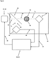
- FIG 1 an exemplary embodiment of a device according to the invention is shown in the state connected to a patient 1 .
- the patient 1 is connected to a dialyzer 10 by means of a blood supply line 14 .
- a blood discharge line 15 feeds the cleaned blood back into the patient's bloodstream.
- the dialyzer 10 is divided into two chambers 12, 13 by means of a semi-permeable membrane 11, with the blood of the patient 1 to be cleaned passing through the first chamber 13 and dialysis fluid containing the blood of the patient 1 passing through the second chamber 12 absorbing waste products and toxic substances.
- the waste products and toxic substances are transported from the patient's 1 blood into the dialysis fluid by means of diffusion and convection via the semipermeable membrane 11.
- the dialysis fluid is fed to the second chamber 12 of the dialyzer 10 by means of an inlet 20.
- a pump for conveying the dialysis fluid is provided in the inlet 20 as well as a valve 60 through which the dialysis fluid can be routed past the dialyzer 10 via a bypass into an outlet 30 for the dialysis fluid instead of into the dialyzer 10 .
- a valve 61 is also arranged in the outflow 30 and is connected to the valve 60 in the inflow 20 by means of the bypass 62
- this now used dialysis fluid is disposed of via the outlet 30 a light-emitting diode 43 working in the UV range, and a detector system 42, which in the present embodiment according to figure 2 consists of a semi-transparent mirror 46 and two photodetectors 44, 45, the absorption of the used dialysis fluid can be determined.
- the measuring device 40 and the detector system 42 is as follows: According to the principle of two-beam spectroscopy as described in figure 2 shown, the light-emitting diode 43 emits UV light with a wavelength of approx. A part 54 of the radiation 53 passes through the semi-transparent mirror 46 and the remaining part 56 of the radiation 53 is reflected by the semi-transparent mirror 46 onto the detector 45 . A certain proportion of the electromagnetic radiation of the part 54 is absorbed by the urinary substances contained in the used dialysis fluid 55 . The portion of portion 54 not absorbed by urinary substances is recorded by detector 44 . The part 56 of the electromagnetic radiation recorded on the detector 45 is thus independent of urinary substances in the dialysis liquid 55 and, via the semi-transparent mirror, is directly proportional to the intensity I of the radiation source.
- the dialysis fluid 55 in the outflow 30 contains urinary substances that were withdrawn from the blood in the dialyzer and these urinary substances absorb electromagnetic radiation with a wavelength of 280 nm
- the absorption of urinary substances in the outflow 30 can be determined using the intensity determined on the detector 44 . In this way, the course of the absorption by substances in the urine can be measured during the treatment, which serves as the basis for the calculation of the Kt/V.
- the signal at the detector 44 is reduced because the absorption increases.
- An e-function is then determined from the course of the absorption, from which the Kt/V value is calculated.
- the problem of aging can occur in particular with the radiation source 41 or the light-emitting diode 43, the outlet 30 and the detector system 42 or the two detectors 44 and 45 and cause a change in the properties.
- the electromagnetic radiation of the light-emitting diode 43 loses intensity as a result of aging at a constant current during the operating time and also reacts with an increase in temperature with a decreasing electromagnetic radiation. Aging also takes place at the detectors 44 Et 45. Due to aging, the semitransparent mirror also influences not only the permeability but also the ratio of the beam path between and I 0 and I 44 and I 45 . Likewise, the outflow 30 can have a constant turbidity.
- the measuring range or the resolution of the detector system 42 or of the detector 44 is optimally used by a predefined desired value I 44_Soll of the intensity of the electromagnetic radiation at the detector 44, at which the electromagnetic radiation has passed through pure dialysis fluid without urinary substances in the outflow 30.
- the regulation can also take place with any other type of regulation, but this would result in a slower transient process.
- the first control process at the beginning of the therapy takes place before the patient 1 is connected or in the bypass 62, in which the pure dialysis liquid is guided past the dialyzer 10 by appropriate adjustment of the valves 60 and 61, with pure dialysis liquid without urinary substances.
- the control process is carried out to the predefined target value of the radiation intensity 1 44_Soll ⁇ U 44_Soll at the detector 44. This compensates for aging by changing the electrical current intensity of the light-emitting diode 43. If necessary, the amplification factors of the electronic detector circuits on the detectors 44 and 45 are adapted, provided that the signal quality allows this.
- the measured value then present at detector 45 is stored as setpoint value U 45 for the second control process and serves as setpoint value during therapy in order to compensate for temperature fluctuations.
- the measured value of U 4t is recorded at the detector 44.
- this procedure also enables a constant measuring range and also a constant signal quality. Aging of the detectors 44 and 45 is negligible during a therapy, ie during a single kidney replacement treatment. During the kidney replacement treatment, the system is then regulated to the desired value U 45 on the detector 45, which enables a stable and constant emitted electromagnetic radiation independent of the dialysis liquid flow. In this way, the temperature drift of the light-emitting diode 43 or of the intensity I o can be compensated.
- the control value of the regulation is the electrical current of the light-emitting diode 43, which is proportional to the intensity I o of the radiation emitted by the light-emitting diode 43.
- purely controlling the detector 44 using a default value at the beginning does not make sense, since influences during the therapy cannot be compensated for.
- the specification of the predefined setpoint in the first control process serves to define the measuring range of the electronics and at the same time defines the measuring resolution of the absorption of the measuring signal.
- Amplifier circuits not shown in the figures within the electronic control 52 convert the signal from the detectors 44 and 45 into a measurement voltage, for which analog/digital converters with microprocessor measurement recording are available.
- This adaptation of the amplifier circuits which can only take place before each individual kidney replacement treatment, could take place automatically before the kidney replacement treatment, in parallel with the regulation of the current of the light-emitting diode 43 . During the treatment, however, only regulation of the current is possible.
- An optimal operating temperature is achieved for the light-emitting diode 43 and the detectors 44 and 45 with the aid of the temperature control.
- the current must be increased as the manipulated variable of the light-emitting diode 43 in order to keep the emitted electromagnetic radiation at a constant intensity as the temperatures rise.
- the current as the manipulated variable of the light-emitting diode 43 must be reduced when the temperatures drop.
- an increase in the current is only possible in the operating range of the light-emitting diode 43 and accelerates the aging process.
- the aim of the temperature control is to operate the light-emitting diode 43 and the detectors 44 & 45 in the optimum temperature range or to quickly reach the optimum temperature range for these components so that a change in temperature can be reduced to a minimum during therapy.
- increased temperatures can occur at the measuring device 40 or the light-emitting diode 43 and/or the detector system 42 or the detectors 44 and 45 due to the heating of the system.
- the self-heating of the system causes it to cool down, resulting in a very low temperature initially.
- the temperature is stabilized with a water-cooled heat sink, which couples the flow temperature of the dialysis fluid directly to the heat sink 43 of the LED and/or the detectors 44&45.
- the thermal capacity of the dialysis fluid is significantly higher than that of the heat sink of the light-emitting diode 43 and therefore defines the temperature, which is possible without additional technical effort. This makes it possible to keep the temperature approximately constant in the operating range of the components and to quickly bring the system into the optimum temperature range.
- the luminous intensity I o must also be stabilized in parallel with the electronic control 52 mentioned above.
- Cooling can also be performed with other active and passive cooling methods.
- passive cooling the temperature of the light-emitting diode 43 or the detectors 44 and 45 can be stabilized via the housing or water cooling.
- a fan can be used as active cooling, which can regulate the temperature depending on the ambient temperature. Direct control with a Peltier element or similar electrothermal converters for temperature stabilization is also possible.
Landscapes
- Physics & Mathematics (AREA)
- Health & Medical Sciences (AREA)
- Spectroscopy & Molecular Physics (AREA)
- General Physics & Mathematics (AREA)
- Engineering & Computer Science (AREA)
- General Health & Medical Sciences (AREA)
- Life Sciences & Earth Sciences (AREA)
- Heart & Thoracic Surgery (AREA)
- Urology & Nephrology (AREA)
- Mathematical Physics (AREA)
- Pathology (AREA)
- Immunology (AREA)
- Biochemistry (AREA)
- Analytical Chemistry (AREA)
- Chemical & Material Sciences (AREA)
- Theoretical Computer Science (AREA)
- Emergency Medicine (AREA)
- Veterinary Medicine (AREA)
- Public Health (AREA)
- Animal Behavior & Ethology (AREA)
- Vascular Medicine (AREA)
- Hematology (AREA)
- Biomedical Technology (AREA)
- Anesthesiology (AREA)
- External Artificial Organs (AREA)
- Surgical Instruments (AREA)
- Investigating Or Analysing Materials By Optical Means (AREA)
Description
- Die Erfindung betrifft eine Vorrichtung zur extrakorporalen Blutbehandlung nach dem Oberbegriff des Patentanspruchs 1.
- Bei Patienten mit reduzierter bzw. überhaupt keiner Nierenfunktion werden Abfallprodukte, einschließlich toxischer Substanzen, mittels einer Nierenersatzbehandlung beseitigt, wobei das Blut des Patienten über einer Blutzuführleitung vom Patienten der künstlichen Niere bzw. dem Dialysator zugeführt wird. In der künstlichen Niere bzw. dem Dialysator wird das Blut des Patienten über eine semipermeable Membran mit Dialysierflüssigkeit in Kontakt gebracht. Die Dialysierflüssigkeit enthält unterschiedliche Salze in einer solchen Konzentration, dass die Abfallprodukte, einschließlich der toxischen Substanzen, mittels Diffusion und Konvektion durch die Membran aus dem Blut des Patienten zur Dialysierflüssigkeit geführt werden. Das so von den Abfallprodukten bereinigte Blut wird über eine an dem Dialysator angeschlossenen Blutabführleitung wieder in den Blutkreislauf des Patienten zurückgeführt.
- Um das Ergebnis einer Nierenersatzbehandlung quantifizieren zu können, ist es notwendig, die Effizienz der Nierenersatzbehandlung unmittelbar bzw. online zu steuern. Deshalb wurde das so genannte Kt/V-Modell entwickelt. Der Kt/V-Wert ist dabei ein Parameter zur Bestimmung der Effektivität einer Nierenersatzbehandlung, wobei die Clearance K für den Volumenstrom der gereinigten harnpflichtigen Substanzen, t für die Behandlungszeit und V für das Verteilungsvolumen des Patienten steht Dabei sind sowohl K als auch V jeweils auf das auf das jeweilige Abfallprodukt bezogen. In der Regel wird die Effizienz bei einer Nierenersatzbehandlung anhand des Harnstoffes als Abfallprodukt beschrieben, so dass K die Harnstoffclearance und V das Harnstoffverteilungsvolumen des Patienten, welches im Wesentlichen dem Körperwassers des Patienten entspricht, beschreibt
- Aus der
EP 1 083 948 A1 und derEP 2 005 982 A1 ist es bekannt, mit Hilfe einer im Ablauf angeordneten Messeinrichtung spektralphotometrisch unter Verwendung von UV-Strahlung und deren Absorption durch harnpflichtige Substanzen in der Dialysierflüssigkeit den Kt/V-Wert bzw. die Reduktionsrate RR für ein bestimmtes Abfallprodukt während der Nierenersatzbehandlung zu bestimmen. - Bei diesen bekannten Vorrichtungen hat sich allerdings herausgestellt, dass eine gleichmäßige Strahlungsintensität der Strahlungsquelle und eine gleichmäßige Empfindlichkeit des Detektorsystems weder über die Betriebszeit der Strahlungsquelle noch während einer einzelnen Nierenersatzbehandlung gewährleistet werden konnte. Somit basiert die Absorptionsmessung in der verbrauchten Dialysierflüssigkeit während verschiedener Behandlungen und auch während einer Behandlungszeit auf veränderlichen Strahlungsintensitäten der Strahlungsquelle und/oder einem veränderten Ausgangssignal bei konstantem Eingangssignal des Detektorsystems. Dies hat zur Folge, dass der auf der Absorptionsmessung basierende Kt/V-Wert bzw. die auf der Absorptionsmessung basierende Reduktionsrate RR für ein bestimmtes Abfallprodukt nicht den tatsächlichen Gegebenheiten entsprechen. Vielmehr ist die Absorptionsmessung in der verbrauchten Dialysierflüssigkeit und damit die Aussage hinsichtlich des Kt/V-Wertes bzw. der Reduktionsrate RR für ein bestimmtes Abfallprodukt verfälscht
- Aufgabe der Erfindung ist es daher, eine Vorrichtung gemäß dem Oberbegriff des Patentanspruchs 1 derart weiterzubilden, dass durch die Absorptionsmessung eine zuverlässige und unverfälschte Aussage über den Kt/V-Wert bzw. der Reduktionsrate RR einer Nierenersatzbehandlung erhalten wird.
- Eine weitere Aufgabe der Erfindung ist es, ein Verfahren zur Verfügung zu stellen, wodurch eine zuverlässige und unverfälschte Aussage über den Kt/V-Wert bzw. der Reduktionsrate RR einer Nierenersatzbehandlung erhalten wird.
- Gelöst wird die vorrichtungsgemäße Aufgabe durch eine Vorrichtung mit den Merkmalen des Patentanspruchs 1. Vorteilhafte Ausgestaltungen der Endungen sind Gegenstand der Unteransprüche 2 bis 12.
- Durch die Erfindung wird eine zuverlässige und unverfälschte Aussage über den Kt/V-Wert bzw. der Reduktionsrate RR einer Nierenersatzbehandlung erhalten, indem Mittel vorgesehen sind, um Alterung der Messeinrichtung wahrend der Betriebszeit und auftretende Anderungen der Intensitat der elektromagnetischen Strahlung der Strahlungsquelle und/oder der Empfindlichkeit des Detektorsystems wahrend Behandlungszeit zu kompensieren.
- Es hat sich nämlich herausgestellt, dass die nachlassende Strahlungsintensität der Strahlungsquelle über deren Betriebszeit in erster Linie auf einen Alterungsprozess der Strahlungsquelle zurückzuführen ist.
Da die Arbeitsintensität I0 der Strahlungsquelle bei solchen Vorrichtungen in der Regel kleiner als die maximale Intensität Imax der Strahlungsquelle ist, lässt sich das auf die Betriebszeit zurückzuführende Nachlassen der Strahlungsintensität einfach durch ein Nachführen der Strahlungsintensität der Strahlungsquelle kompensieren. Durch das Detektorsystem wird somit zu Beginn jeder Behandlung die Strahlungsintensität nach Absorption durch unverbrauchte Dialysierflüssigkeit gemessen. Sobald Abweichungen dieser Strahlungsintensität von der Strahlungsintensität des vordefinierten Sollwerts auftreten, wir diese Abweichung kompensiert. Diese Maßnahme führt dazu, dass die Absorptionsmessungen der erfindungsgemäßen Vorrichtung über deren gesamte Betriebszeit normierbar sind, da immer die gleiche Strahlungsintensität nach Absorption durch unverbrauchte Dialysierflüssigkeit zu Grunde gelegt wird. - Weiterhin hat sich auch gezeigt, dass während einer Nierenersatzbehandlung eine Konstanz eines Referenzsignal der Strahlungsintensität, welches durch Detektion der Strahlungsintensität ohne Absorption generiert wird, ebenfalls nicht gewährleistet werden kann. Wie sich herausgestellt hat, liegt die Ursache hierfür in Temperaturschwankungen sowohl an der Strahlungsquelle als auch am Detektorsystem. Erfindungsgemäß ist deshalb als Mittel zur Kompensation eine Temperaturregelung vorgesehen, durch welche die Temperatur der Strahlungsquelle auf einen vordefinierten Arbeitstemperaturbereich ΔT1 und/oder die Temperatur des Detektorsystems auf einen vordefinierte Arbeitstemperaturbereich ΔT2 regelbar ist Durch diese Maßnahme hat sich eine deutliche Stabilisierung sowohl der Signalintensität der Strahlungsquelle als auch der Empfindlichkeit des Detektorssystems gezeigt, wobei durch Kombination der beiden alternativen Maßnahme die Stabilität und damit die Aussagekraft der letztendlich erhalten Ergebnisse der Kt/V-Werte und der Reduktionsrate RR nochmals signifikant gesteigert werden kann.
- Allein die Kompensation der Änderung der Intensität der elektromagnetischen Strahlung der Strahlungsquelle oder der Empfindlichkeit des Detektorsystems führt bereits zu deutlich verbesserten Aussagen über den Kt/V-Wert bzw. die Reduktionsrate RR für ein bestimmtes Abfallprodukt. Eine nochmals signifikante Verbesserung der dieser Aussagen lässt sich erreichen, wenn beide Maßnahmen - zum einen eine Kompensation der Änderung der Intensität der elektromagnetischen Strahlung der Strahlungsquelle und zum anderen eine Kompensation der Änderung Empfindlichkeit des Detektorsystems - in der erfindungsgemäßen Vorrichtung integriert sind.
- Erfindungsgemäß ist vorgesehen, dass als Mittel zur Kompensation des Alterungsprozesses der Strahlungsquelle eine elektronische Regelung vorgesehen ist, mit deren Hilfe die Intensität I der elektromagnetischen Strahlung der Strahlungsquelle derart regelbar ist, dass am Detektorsystem vordefinierte Intensitäten I44, nach Absorption durch unverbrauchte Dialysierflüssigkeit, und/oder I45, ohne Absorption durch unverbrauchte Dialysierflüssigkeit, detektierbar sind.
- Dabei hat es sich als vorteilhaft erwiesen, dass die elektronische Regelung als Regelkreis ausgebildet ist, da solche Regelkreise bereits technisch ausgereift und einfach handhabbar sind.
- Da die Absorption von harnpflichtige Substanzen im W-Bereich und im Wesentlichen bei 280nm sehr gut ist, bietet es sich an, dass die Strahlungsquelle als eine Leuchtdiode ausgebildet ist, welche in ihrem Arbeitstemperaturbereich ΔT1 elektromagnetische Strahlung im Wesentlichen der Wellenlänge 280nm emittiert.
- Vorteilhaft ist weiterhin, wenn das Detektorsystem aus wenigstens einem fotodetektor vorzugsweise aus zwei Fotodetektoren besteht. Bei Verwendung nur eines Fotodetektor muss allerdings davon ausgegangen werden, dass die Signalintensität der von der Strahlungsquelle emittierten Strahlung zeitlich nicht konstant ist, um die Absorption der Dialysierflüssigkeit immer auf derselben Basis zu bestimmen. Deutlich besser ist es deshalb zwei Detektoren zu verwenden, wobei einer die Intensität der Strahlungsquelle und einer die Intensität der Strahlung nach Durchgang durch die die verbrauchte Dialysierflüssigkeit misst
- Ein besonders effektive bevorzugte Ausgestaltung der Erfindung besteht daher darin, dass im Strahlengang der elektromagnetischen Strahlung zwischen der Strahlungsquelle und dem Abfluss für verbrauchte Dialysierflüssigkeit ein teildurchlässiger Spiegel oder eine optische Einrichtung zur Strahlaufteilung oder -umlenkung angeordnet ist, so dass ein Teil der elektromagnetischen Strahlung durch die verbrauchte Dialysierflüssigkeit auf den ersten Fotodetektor und der restliche Teil direkt auf den zweiten Detektor geleitet wird.
- Nach einer weiteren bevorzugten Ausgestaltung der Erfindung ist die Regelgröße des Regelkreises die Intensität der elektromagnetischen Strahlung am ersten Detektor und die Stellgröße der elektrische Strom der Strahlungsquelle, wobei die dann ermittelte Intensität am zweiten Detektor als Referenzwert für die jeweilige Nierenersatzbehandlung abspeicherbar ist Durch diese Maßnahme ist eine besonders gute Regelung der Strahlungsintensität der elektromagnetischen Strahlungsquelle während der gesamten Betriebszeit der Strahlungsquelle gewährleistet
- In diesem Zusammenhang hat es sich als besonders vorteilhaft erwiesen, dass die am zweiten Detektor ermittelte Referenzgröße der Intensität während der jeweiligen Nierenersatzbehandlung die Regelgröße eines zweiten Regelkreises ist und dass der elektrische Strom der Strahlungsquelle die Stellgröße dieses zweiten Regelkreises ist Dadurch kann während einer Nierenersatzbehandlung eine Änderung dieser Referenzgröße im Wesentlichen ohne Zeitverzögerung kompensiert werden.
- Um die Temperaturregelung möglichst einfach und effektiv zu gestalten, hat es sich als vorteilhaft erwiesen, dass die Temperaturregelung einen Kühlkörpers für die Leuchtdiode und/oder das Detektorsystem bzw. die Detektoren aufweist
- Alternativ oder zusätzlich ist es natürlich auch möglich, dass die Temperaturregelung eine Wasserkühlung für die Leuchtdiode und/oder die Detektoren aufweist.
- Weiterhin alternativ oder zusätzlich kann die Temperaturregelung einen oder mehrere Lüfter für die Leuchtdiode und/oder die Detektoren aufweisen.
- Als besonders vorteilhaft hat es sich erwiesen, wenn die Temperaturregelung alternativ oder zusätzlich einen oder mehrere elektrothermische Wandler, beispielsweise Peltier-Elemente zur Temperaturregelung der Leuchtdiode und/oder der Detektoren aufweist
- Weitere Ziele, Vorteile, Merkmale und Anwendungsmöglichkeiten der vorliegenden Erfindung ergeben sich aus der nachfolgenden Beschreibung der Ausführungsbeispiele anhand der Zeichnungen. Dabei bilden alle beschriebenen und/oder bildlich dargestellten Merkmale für sich oder in beliebiger sinnvoller Kombination den Gegenstand der vorliegenden Erfindung, auch unabhängig von ihrer Zusammenfassung in den Ansprüchen und deren Rückbeziehung.
-
- Figur 1:
- eine schematische Darstellung eines Ausführungsbeispiels einer erfindungsgemäßen Vorrichtung,
- Figur 2:
- eine schematische Darstellung eines Ausführungsbeispiels einer Messeinrichtung bzw. des Detektorsystems einer erfindungsgemäßen Vorrichtung,
- In
Figur 1 ist ein Ausführungsbeispiel einer erfindungsgemäßen Vorrichtung in an einen Patienten 1 angeschlossenen Zustand dargestellt. Dabei ist der Patient 1 mittels einer Blutzuführleitung 14 mit einen Dialysator 10 verbunden. Von dem Dialysator führt eine Blutabführleitung 15 das gereinigte Blut wieder dem Blutkreislauf des Patienten zu. - Der Dialysator 10 ist mittels einer semipermeablen Membran 11 in zwei Kammern 12, 13 geteilt, wobei durch die erste Kammer 13 das zu reinigende Blut des Patienten 1 und durch die zweite Kammer 12 Dialysierflüssigkeit, welche in der Lage ist die im Blut des Patienten 1 enthaltenen Abfallprodukte und toxische Substanzen aufzunehmen, geführt wird. Der Transport der Abfallprodukte und toxischen Substanzen vom Blut des Patienten 1 in die Dialysierflüssigkeit erfolgt mittels Diffusion und Konvektion über die semipermeable Membran 11. Die Dialysierflüssigkeit wird mittels eines Zulaufs 20 der zweiten Kammer 12 des Dialysators 10 zugeführt. Dabei ist im Zulauf 20 eine Pumpe für die Förderung der Dialysierflüssigkeit ebenso vorgesehen wie ein Ventil 60, durch welches die Dialysierflüssigkeit anstatt in den Dialysator 10 über einen Bypass an diesem vorbei in einen Abfluss 30 für die Dialysierflüssigkeit geleitet werden kann. Im Abfluss 30 ist ebenfalls ein Ventil 61 angeordnet, welches mittels dem Bypass 62 mit dem Ventil 60 im Zulauf 20 verbunden ist
- Nachdem im Dialysator 10 Abfallprodukte und toxische Substanzen vom Blut des Patienten 1 in die Dialysierflüssigkeit transportiert wurden, wird diese nunmehr verbrauchte Dialysierflüssigkeit über den Ablauf 30 entsorgt Im Ablauf 30 ist eine Messeinrichtung 40 angeordnet, mit welcher mittels einer Strahlungsquelle 41 für elektromagnetische Strahlung, insbesondere mit einer im UV-Bereich arbeitenden Leuchtdiode 43, und einem Detektorsystem 42, welches im vorliegenden Ausführungsbeispiel gemäß
Figur 2 aus einem halbdurchlässigen Spiegel 46 und zwei Fotodetektoren 44, 45 besteht, die Absorption der verbrauchten Dialysierflüssigkeit bestimmt werden kann. - Die Funktionsweise der Messeinrichtung 40 und des Detektorsystems 42 ist folgende: Nach dem Prinzip der Zweistrahlspektroskopie wie sie in
Figur 2 dargestellt ist emittiert die Leuchtdiode 43 als Strahlung 53 UV-Licht einer Wellenlänge von ca. 280nm, welches von dem halbdurchlässigen Spiegel 46 aufgeteilt wird. Ein Teil 54 der Strahlung 53 passiert den halbdurchlässigen Spiegel 46 und der restliche Teil 56 der Strahlung 53 wird von dem halbdurchlässigen Spiegel 46 auf den Detektor 45 reflektiert. Durch die in der verbrauchten Dialysierflüssigkeit 55 enthaltenen harnpflichtigen Substanzen wird ein gewisser Anteil der elektromagnetischen Strahlung des Teils 54 absorbiert. Der nicht von harnpflichtigen Subtanzen absorbierte Anteil des Teils 54 wird durch den Detektor 44 aufgezeichnet. Der am Detektor 45 aufgezeichnet Teil 56 der elektromagnetischen Strahlung ist somit unabhängig von harnpflichtigen Subtanzen in der Dialysierflüssigkeit 55 und über den halbdurchlässigen Spiegel direkt proportional zur Intensität I der Strahlungsquelle. - Da in der Dialysierflüssigkeit 55 im Abfluss 30 harnpflichtige Substanzen, die dem Blut im Dialysator entzogen wurden, enthalten sind und diese harnpflichtige Substanzen elektromagnetische Strahlung der Wellenlänge 280nm absorbieren kann mit Hilfe der am Detektor 44 bestimmten Intensität die Absorption von harnpflichtigen Substanzen im Abfluss 30 bestimmt werden. So ist der Verlauf der Absorption durch harnpflichtige Subtanzen während der Behandlung messbar, der als Grundlage zur Berechnung des Kt/V dient.
- Mit steigender Konzentration von harnpflichtigen Subtanzen in der Dialysierflüssigkeit 55 wird das Signal am Detektor 44 verringert, da sich die Absorption erhöht. Aus dem Verlauf der Absorption wird dann eine e-Funktion ermittelt, aus welcher der Kt/V-Wert berechnet wird.
- Um eine exakte Aussage über die Absorption während der Behandlungszeit zu bekommen, müssen allerdings Schwankungen der Intensität Io der Leuchtdiode 43 vermieden werden. Gewöhnlich erfolgt eine Kompensation von Schwankungen einer Lichtquelle bei einer Zweistrahlspektroskopie, wie Sie hier vorliegt, durch folgende Formel (bezogen auf die Absorption A), wobei die Intensitäten I44 und I45 an den Detektoren 44 und 45 in entsprechenden Signale umgewandelt werden:
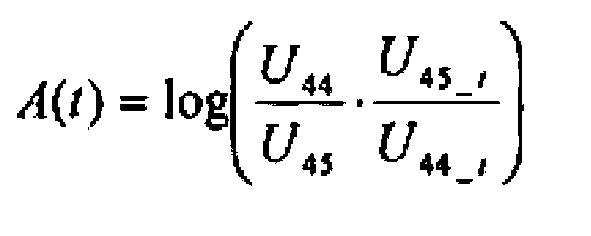
- mit U44 = Signal am Detektor 44 mit unverbrauchter Dialysierflüssigkeit
- U45 = Signal am Detektor 45 zu Beginn
- U44_t = Signal am Detektor 44 zum Zeitpunkt t während der Therapie
- U45_t = Signal am Detektor 45 zum Zeitpunkt t während der Therapie
- Mit der Vorrichtung gemäß den
Figuren 1 und2 wird die Intensität Io während der Therapie konstant gehalten, so dass U45=U45_t ∼ Io, wobei Io im Arbeitsbereich der Leuchtdiode frei wählbar ist Damit reduziert sich die Gleichung für die Absorption A auf:
- Die Absorption ergibt einen Kurvenverlauf, der durch eine e-Funktion beschrieben werden kann, aus der mit A(t) = a*exp(b*t) der Kt/V = 0b*t berechnet werden kann.
- Um die bei den bekannten Vorrichtungen auftretenden Messfehler, insbesondere durch Alterung und Temperaturinstabilität zu kompensieren gibt es zwei anspruchsgemäße Ansätze:
- Signalstabilität durch elektronische Regelung der emittierten elektromagnetischen Strahlung auf vordefinierte Level
- Temperaturstabilität durch Temperaturregelung
- Die Problematik der Alterung kann insbesondere bei der Strahlungsquelle 41 bzw. der Leuchtdiode 43, dem Ablauf 30 sowie den Detektorsystem 42 bzw. den beiden Detektoren 44 und 45 auftreten und eine Veränderung der Eigenschaften bewirken.
- Mit Hilfe der elektronischen Regelung ist es möglich, Veränderungen durch Alterung und Temperaturschwankungen sehr präzise zu kompensieren. Die elektromagnetische Strahlung der Leuchtdiode 43 verliert durch Alterung bei einem konstanten Strom während der Betriebszeit an Intensität und reagiert ebenfalls bei Erhöhung der Temperatur mit einer sinkenden elektromagnetischen Strahlung. Ebenso erfolgt eine Alterung an den Detektoren 44 Et 45. Der halbdurchlässige Spiegel beeinflusst durch Alterung neben der Durchlässigkeit auch das Verhältnis des Strahlengangs zwischen und I0 und I44 und I45. Ebenso kann es beim Abfluss 30 zu einer konstanten Trübung kommen.
- Durch einen vordefinierten Sollwert I44_Soll der Intensität der elektromagnetische Strahlung am Detektor 44, bei dem die elektromagnetische Strahlung reine Dialysierflüssigkeit ohne harnpflichtige Stoffe im Abfluss 30 durchquert hat, wird der Messbereich beziehungsweise die Auflösung des Detektorsystems 42 bzw. des Detektors 44 optimal genutzt. Dadurch werden Veränderungen im System durch Alterung erkannt und kompensiert, wobei dadurch auch eine Überprüfung der Leistungsfähigkeit des Messsystems erfolgt Damit wird gewährleistet, das die Signalqualität, der Messbereich, die Messauflösung und die Reproduzierbarkeit während der gesamten Lebensdauer konstant ist
- Die Gleichung für die Absorption ergibt sich daher mit dem Sollwert I44_Soll zu:

- Die elektrische Regelung erfolgt in zwei Schritten:
- Zu Beginn der Nierenersatzbehandlung vor Anschluss des Patienten bzw. im Bypass befindet sich reine Dialysierflüssigkeit ohne harnpflichtige Subtanzen im Abfluss 30. In diesem Betriebszustand erfolgt zunächst eine Regelung des elektrischen Stroms der Strahlungsquelle 41 als Stellgröße, so dass am Detektor 44 der vordefinierten Sollwert I44_Soll der Strahlungsintensität als Eingangssignal detektiert. Bei Erreichen des vordefinierten Sollwerts I44_Soll am Detektor 44 wird der Intensitätswert I45 von Detektor 45 gespeichert und dient in einer zweiten Regelung während der folgenden Nierenersatzbehandlung als Sollwert I45_Soll. Es erfolgt also nun eine Regelung des elektrischen Stroms der Strahlungsquelle 41 bzw. der Leuchtdiode als Stellgröße auf den Intensitätswert I45_Soll am Detektor 45.
- Die Regelung erfolgt mit einem adaptiven Regler, der zunächst automatisiert die von der Leuchtdiode 43, den Detektor 44, dem teildurchlässigen Spiegel 46 sowie dem Abfluss 30 abhängige Übertragungsfunktion F44(43,44,46,30))=U44 und die von der Leuchtdiode 43, den Detektor 45 und dem teildurchlässigen Spiegel 46 abhängige Übertragungsfunktion F45(43,46,45))=U45 des Systems erfasst. Die Regelung kann ebenfalls mit jeder anderen Art von Regelung erfolgen, was jedoch einen langsameren Einschwingvorgang zur Folge hätte.
- Der erste Regelvorgang zu Beginn der Therapie erfolgt vor dem Anschluss des Patienten 1 bzw. im Bypass 62, bei dem durch entsprechende Einstellung der Ventile 60 und 61 die reine Dialysierflüssigkeit an dem Dialysator 10 vorbeigeführt wird, mit reiner Dialysierflüssigkeit ohne harnpflichtige Subtanzen. Mit Hilfe der adaptiven Regelung und der Übertragungsfunktion F44 erfolgt der Regelvorgang auf den vordefinierten Sollwert der Strahlungsintensität 144_Soll ∼ U44_Soll am Detektor 44. Damit erfolgt die Kompensation der Alterung durch Änderung der elektrischen Stromstärke der Leuchtdiode 43. Wenn nötig können ebenfalls die Verstärkungsfaktoren der elektronischen Detektorschaltungen an den Detektoren 44 und 45 angepasst werden, sofern die Signalqualität dies zulässt. Der dann anliegende Messwert an Detektor 45 wird als Sollwert U45 für den zweiten Regelvorgang gespeichert und dient während der Therapie als Sollwert, um Temperaturschwankungen zu kompensieren. Dabei ist die Absorption A=0, da U44 = U44t.
Nach dem Anschluss des Patienten 1 erfolgt die Messwertaufnahme von U4t am Detektor 44. Durch harnpflichtige Substanzen ändert sich der Messwert am Detektor 44 und die Absorption ergibt sich aus:
- Neben der Kompensation von Temperaturschwankungen ermöglicht diese Vorgehensweise auch einen konstanten Messbereichs und ebenfalls eine gleich bleibende Signalqualität. Während einer Therapie, also während einer einzigen Nierenersatzbehandlung, ist eine Alterung der Detektoren 44 und 45 zu vernachlässigen. Das Systems wird während der Nierenersatzbehandlung dann auf den Sollwert U45 am Detektor 45 geregelt, der unabhängig vom Dialysierflüssigkeitsfluss eine stabile und konstante emittierte elektromagnetische Strahlung ermöglicht. Damit kann der Temperaturdrift der Leuchtdiode 43 bzw. der Intensität Io kompensiert werden. Der Stellwert der Regelung ist der elektrische Strom der Leuchtdiode 43, der proportional zur Intensität Io der durch die Leuchtdiode 43 emittierten Strahlung ist. Eine reine Regelung auf den Detektor 44 durch einen Vorgabewert zu Beginn ist jedoch nicht sinnvoll, da Einflüsse während der Therapie nicht kompensiert werden können.
- Die Vorgabe des vordefinierten Sollwert im ersten Regelungsprozess dient zur Definition des Messbereichs der Elektronik und definiert gleichzeitig die Messauflösung der Absorption des Messsignals.
- In den Figuren nicht dargestellte Verstärkerschaltungen innerhalb derelektronischen Regelung 52 wandeln das Signal der Detektoren 44 und 45 in eine Messspannung um, für die Analog-Digital-Wandler mit einer Mikroprozessor-Messwertaufnahme zur Verfügung stehen. Diese Anpassung der Verstärkerschaltungen, welche nur vor jeder einzelnen Nierenersatzbehandlung erfolgen kann, könnte automatisch vor der Nierenersatzbehandlung parallel zu Regelung des Stroms der Leuchtdiode 43 erfolgen. Während der Behandlung ist allerdings nur eine Regelung des Stroms möglich.
- Mit Hilfe der Temperaturregelung wird für die Leuchtdiode 43 und die Detektoren 44 und 45 eine optimale Betriebstemperatur erreicht. Bei hohen Temperaturen muss der Strom als Stellgröße der Leuchtdiode 43 erhöht werden, um die emittierte elektromagnetische Strahlung bei steigenden Temperaturen bei einer konstanten Intensität zu halten. Umgekehrt muss bei sinkenden Temperaturen der Strom als Stellgröße der Leuchtdiode 43 gesenkt werden. Eine Erhöhung des Stroms ist jedoch nur im Betriebsbereich der Leuchtdiode 43 möglich und beschleunigt den Alterungsprozess. In einem Dialysegerät treten erfahrungsgemäß ernorme Temperaturschwankungen auf. Deshalb ist es sinnvoll Temperaturschwankungen durch eine Temperaturregelung 51 zu kompensieren, so dass die Vorrichtung in dem optimalen Temperaturbereich betrieben werden kann. Durch solche Maßnahmen wird auch der Alterungsprozess verlangsamt
- Ziel der Temperaturregelung ist, die Leuchtdiode 43 und die Detektoren 44 & 45 im optimalen Temperaturbereich zu betreiben bzw. schnell den optimalen Temperaturbereich für diese Komponenten zu erreichen, damit während der Therapie eine Änderung der Temperatur auf ein Minimum reduziert werden kann. Nach der Desinfektion kann es durch Erhitzung des Systems zu erhöhten Temperaturen an der Messeinrichtung 40 bzw. der Leuchtdiode 43 und/oder dem Detektorsystem 42 bzw. den Detektoren 44 und 45 kommen. Ferner hat beim Einschalten der Vorrichtung aus dem kalten Zustand die Eigenerwärmung des Systems eine Abkühlung zur Folge, wodurch zu Beginn eine sehr geringe Temperatur vorhanden ist. Daher ist es notwendig die Temperatur so schnell wie möglich in den Betriebsbereich der Komponenten zu bringen, während die Vorrichtung zur Nierenersatzbehandlung vorbereitet wird, um zu Beginn der Therapie bzw. während der Identifikation des System durch die oben beschriebene elektronische Regelung 52 bereits im Sollbereich der Temperatur zu sein. Damit ist es möglich auch sehr geringe Abweichungen der Detektoren 44 und 45 bezüglich eines Signaldrifts durch Temperaturänderungen auf ein Minimum zu reduzieren.
- Die Temperaturstabilisierung erfolgt mit einem Kühlkörper mit Wasserkühlung, der die Flusstemperatur der Dialysierflüssigkeit direkt mit dem Kühlkörper 43 der LED und/oder die Detektoren 44&45 koppelt. Die Wärmekapazität der Dialysierflüssigkeit ist deutlich höher als die des Kühlkörpers der Leuchtdiode 43 und definiert daher die Temperatur, was ohne zusätzlichen technischen Aufwand möglich ist. Damit ist es möglich die Temperatur näherungsweise konstant im Betriebsbereich der Komponenten zu halten und das System schnell in den optimalen Temperaturbereich zu bringen.
- Ohne enormen zusätzlichen Aufwand ist es jedoch nicht möglich die Temperatur so stabil zu halten, dass sie keinen weiteren Einfluss auf die Intensität der durch die Leuchtdiode 43 emittierte Strahlung hat. Daher muss parallel noch eine Stabilisierung der Leuchtintensität Io mit der oben genannten elektronischen Regelung 52 erfolgen.
- Eine Kühlung kann ebenfalls mit anderen aktiven und passiven Kühlmethoden durchgeführt werden. Als passive Kühlung kann die Leuchtdiode 43 bzw. die Detektoren 44 und 45 über das Gehäuse oder eine Wasserkühlung temperaturstabilisiert werden. Als aktive Kühlung ist der Einsatz eines Lüfters möglich, der die Temperatur abhängig von der Umgebungstemperatur regeln kann. Ebenso ist eine direkte Regelung mit einem Peltier-Element oder ähnlichen elektrothermischen Wandlern zur Temperaturstabilisierung möglich.
-
- 1 --
- Patient
- 10 --
- Dialysator
- 11 --
- Membran
- 12 --
- Kammer
- 13 --
- Kammer
- 14 --
- Blutzuführleitung
- 15 --
- Blutabführleitung
- 20 --
- Zulauf
- 30 --
- Ablauf
- 40 --
- Messeinrichtung
- 41 --
- Strahlungsquelle
- 42 --
- Detektorsystem
- 43 --
- Leuchtdiode
- 44 --
- Detektor
- 45 --
- Detektor
- 46 --
- halbdurchlässiger Spiegel
- 50 --
- Mittel
- 51
- -- Temperaturregelung
- 52 --
- elektronische Regelung
- 53 --
- Strahlengang
- 54 --
- Teil der Strahlung
- 55 --
- verbrauchte Dialysierflüssigkeit
- 56 --
- Teil der Strahlung
- 57 --
- Signalleitung
- 58 --
- Signalleitung
- 59 --
- Signalleitung
- 60 --
- Ventil
- 61 --
- Ventil
- 62 --
- Bypass
- 63 --
- Pumpe
Claims (12)
- Vorrichtung zur extrakorporalen Blutbehandlung mit einem Dialysator (10), der durch eine semipermeable Membran (11) in eine erste und zweite Kammer geteilt ist, wobei die erste Kammer (12) in einem Dialysierflüssigkeitsweg angeordnet ist und die zweite Kammer (13) mittels einer Blutzuführleitung (14) und einer Blutabführleitung (15) mit dem Blutkreislauf eines Patienten (1) verbindbar ist,- einem Zulauf (20) für frische Dialysierflüssigkeit,- einem Ablauf (30) für verbrauchte Dialysierflüssigkeit,- einer in dem Ablauf (30) angeordneten Messeinrichtung (40) zur Bestimmung der Absorption der durch den Ablauf (30) fließenden verbrauchten Dialysierflüssigkeit, wobei die Messeinrichtung (40) wenigstens eine Strahlungsquelle (41) für im Wesentlichen monochromatische elektromagnetische Strahlung sowie ein Detektorsystem (42) zur Detektion der Intensität der elektromagnetischen Strahlung aufweist, dadurch gekennzeichnet, dassMittel (50) vorgesehen sind, um auftretende Änderungen der Intensität der elektromagnetischen Strahlung der Strahlungsquelle (41) und/oder der Empfindlichkeit des Detektorsystems (42) zu kompensieren, wobei
als Mittel (50) eine Temperaturregelung (51) vorgesehen ist, durch welche die Temperatur der Strahlungsquelle (41) auf vordefinierte Arbeitstemperaturen T1 und/oder die Temperatur des Detektorsystems (42) auf vordefinierte Arbeitstemperaturen T2 regelbar ist, wobei für das Mittel (50) zusätzlich eine elektronische Regelung (52) vorgesehen ist, mit deren Hilfe die Intensität I der elektromagnetischen Strahlung der Strahlungsquelle (41) derart regelbar ist, dass am Detektorsystem (42) vordefinierte Intensitäten I44, nach Absorption durch unverbrauchte Dialysierflüssigkeit, und/oder I45, ohne Absorption durch unverbrauchte Dialysierflüssigkeit, detektierbar sind. - Vorrichtung nach Anspruch 1, dadurch gekennzeichnet, dass die elektronische Regelung (52) als Regelkreis ausgebildet ist
- Vorrichtung nach einem der vorherigen Ansprüche, dadurch gekennzeichnet, dass die Strahlungsquelle (41) als eine Leuchtdiode (43) ausgebildet ist.
- Vorrichtung nach Anspruch 3, dadurch gekennzeichnet, dass die Leuchtdiode (43) im Wesentlichen elektromagnetische Strahlung der Wellenlänge 280nm emittiert.
- Vorrichtung nach einem der vorherigen Ansprüche, dadurch gekennzeichnet, dass das Detektorsystem (42) aus wenigstens einem Fotodetektor vorzugsweise aus zwei Fotodetektoren (44, 45) besteht.
- Vorrichtung nach Anspruch 5, dadurch gekennzeichnet, dass im Strahlengang der elektromagnetischen Strahlung zwischen Strahlungsquelle (41) und Abfluss (30) für verbrauchte Dialysierflüssigkeit ein teildurchlässiger Spiegel (46) oder eine optische Einrichtung zur Strahlaufteilung oder -umlenkung angeordnet ist.
- Vorrichtung nach einem der Ansprüche 3 bis 6, dadurch gekennzeichnet, dass die Regelgröße die Intensität I44 der elektromagnetischen Strahlung am ersten Detektor (44) ist und dass die Stellgröße der elektrische Strom der Strahlungsquelle (41, 43) ist und die Intensität I45 am Detektor (45) als Referenzwert I45 abspeicherbar ist.
- Vorrichtung nach Anspruch 7, dadurch gekennzeichnet, dass die Referenzgröße I45 die Regelgröße eines zweiten Regelkreises ist und dass die Stellgröße der elektrische Strom der Strahlungsquelle (41, 43) ist.
- Vorrichtung nach einem der vorherigen Ansprüche, dadurch gekennzeichnet, dass die Temperaturregelung (51) einen Kühlkörpers für die Leuchtdiode (43) und/oder das Detektorsystem (42) bzw. die Detektoren (44, 45) aufweist.
- Vorrichtung nach einem der Ansprüche 1 bis 7, dadurch gekennzeichnet, dass die Temperaturregelung (51) eine Wasserkühlung für die Leuchtdiode (43) und/oder die Detektoren (44, 45) aufweist.
- Vorrichtung nach einem der Ansprüche 1 bis 8, dadurch gekennzeichnet, dass die Temperaturregelung (51) einen oder mehrere Lüfter für die Leuchtdiode (43) und/oder die Detektoren (44, 45) aufweist.
- Vorrichtung nach einem der Ansprüche 1 bis 9, dadurch gekennzeichnet, dass die Temperaturregelung (51) einen oder mehrere elektrothermischen Wandler, beispielsweise Peltier-Elemente zur Temperaturregelung der Leuchtdiode (43) und/oder der Detektoren (44, 45) aufweist.
Priority Applications (12)
| Application Number | Priority Date | Filing Date | Title |
|---|---|---|---|
| AT09001890T ATE524205T1 (de) | 2009-02-11 | 2009-02-11 | Vorrichtung zur extrakorporalen blutbehandlung |
| ES09001890T ES2372563T5 (es) | 2009-02-11 | 2009-02-11 | Dispositivo para el tratamiento extracorporal de sangre |
| PL09001890.4T PL2218472T5 (pl) | 2009-02-11 | 2009-02-11 | Urządzenie do pozaustrojowej obróbki krwi |
| EP09001890.4A EP2218472B2 (de) | 2009-02-11 | 2009-02-11 | Vorrichtung zur extrakorporalen Blutbehandlung |
| DE202009017986U DE202009017986U1 (de) | 2009-02-11 | 2009-02-11 | Regelung und Kühlung des UV-Sensors zur Kompensation eines Temperaturdifts zu Erhaltung des Messbereichs |
| RU2011137416/14A RU2529692C2 (ru) | 2009-02-11 | 2010-02-05 | Устройство для экстракорпоральной очистки крови |
| CN201080007333.7A CN102325555B (zh) | 2009-02-11 | 2010-02-05 | 体外血液处理的设备 |
| EP10704748A EP2396051A1 (de) | 2009-02-11 | 2010-02-05 | Vorrichtung zur extrakorporalen blutbehandlung |
| BRPI1008085A BRPI1008085B8 (pt) | 2009-02-11 | 2010-02-05 | aparelho para tratamento extracorpóreo de sangue |
| PCT/EP2010/000737 WO2010091826A1 (de) | 2009-02-11 | 2010-02-05 | Vorrichtung zur extrakorporalen blutbehandlung |
| US13/148,371 US8834720B2 (en) | 2009-02-11 | 2010-02-05 | Apparatus for the extracorporeal treatment of blood |
| RU2014133177/14A RU2594440C2 (ru) | 2009-02-11 | 2010-02-05 | Устройство для экстракорпоральной очистки крови и способ компенсации изменений интенсивности источника электромагнитного излучения в нем |
Applications Claiming Priority (1)
| Application Number | Priority Date | Filing Date | Title |
|---|---|---|---|
| EP09001890.4A EP2218472B2 (de) | 2009-02-11 | 2009-02-11 | Vorrichtung zur extrakorporalen Blutbehandlung |
Publications (3)
| Publication Number | Publication Date |
|---|---|
| EP2218472A1 EP2218472A1 (de) | 2010-08-18 |
| EP2218472B1 EP2218472B1 (de) | 2011-09-14 |
| EP2218472B2 true EP2218472B2 (de) | 2022-03-16 |
Family
ID=40885966
Family Applications (2)
| Application Number | Title | Priority Date | Filing Date |
|---|---|---|---|
| EP09001890.4A Active EP2218472B2 (de) | 2009-02-11 | 2009-02-11 | Vorrichtung zur extrakorporalen Blutbehandlung |
| EP10704748A Withdrawn EP2396051A1 (de) | 2009-02-11 | 2010-02-05 | Vorrichtung zur extrakorporalen blutbehandlung |
Family Applications After (1)
| Application Number | Title | Priority Date | Filing Date |
|---|---|---|---|
| EP10704748A Withdrawn EP2396051A1 (de) | 2009-02-11 | 2010-02-05 | Vorrichtung zur extrakorporalen blutbehandlung |
Country Status (10)
| Country | Link |
|---|---|
| US (1) | US8834720B2 (de) |
| EP (2) | EP2218472B2 (de) |
| CN (1) | CN102325555B (de) |
| AT (1) | ATE524205T1 (de) |
| BR (1) | BRPI1008085B8 (de) |
| DE (1) | DE202009017986U1 (de) |
| ES (1) | ES2372563T5 (de) |
| PL (1) | PL2218472T5 (de) |
| RU (2) | RU2529692C2 (de) |
| WO (1) | WO2010091826A1 (de) |
Families Citing this family (38)
| Publication number | Priority date | Publication date | Assignee | Title |
|---|---|---|---|---|
| US9358331B2 (en) | 2007-09-13 | 2016-06-07 | Fresenius Medical Care Holdings, Inc. | Portable dialysis machine with improved reservoir heating system |
| US8040493B2 (en) | 2007-10-11 | 2011-10-18 | Fresenius Medical Care Holdings, Inc. | Thermal flow meter |
| US8597505B2 (en) | 2007-09-13 | 2013-12-03 | Fresenius Medical Care Holdings, Inc. | Portable dialysis machine |
| US8240636B2 (en) | 2009-01-12 | 2012-08-14 | Fresenius Medical Care Holdings, Inc. | Valve system |
| US8535522B2 (en) | 2009-02-12 | 2013-09-17 | Fresenius Medical Care Holdings, Inc. | System and method for detection of disconnection in an extracorporeal blood circuit |
| US9308307B2 (en) | 2007-09-13 | 2016-04-12 | Fresenius Medical Care Holdings, Inc. | Manifold diaphragms |
| US8105487B2 (en) | 2007-09-25 | 2012-01-31 | Fresenius Medical Care Holdings, Inc. | Manifolds for use in conducting dialysis |
| CA3057807C (en) | 2007-11-29 | 2021-04-20 | Thomas P. Robinson | System and method for conducting hemodialysis and hemofiltration |
| AU2009302327C1 (en) | 2008-10-07 | 2015-09-10 | Fresenius Medical Care Holdings, Inc. | Priming system and method for dialysis systems |
| CA2739807C (en) | 2008-10-30 | 2017-02-28 | Fresenius Medical Care Holdings, Inc. | Modular, portable dialysis system |
| WO2010114932A1 (en) | 2009-03-31 | 2010-10-07 | Xcorporeal, Inc. | Modular reservoir assembly for a hemodialysis and hemofiltration system |
| JP6027720B2 (ja) | 2009-12-14 | 2016-11-16 | 日機装株式会社 | 血液浄化装置 |
| JP2011120821A (ja) | 2009-12-14 | 2011-06-23 | Nikkiso Co Ltd | 血液浄化装置 |
| DE102010047215A1 (de) * | 2010-09-29 | 2012-03-29 | Bbraun Avitum Ag | Dialysat-Profiling gesteuert durch UV-Kontrolle |
| AT510631B1 (de) | 2010-10-20 | 2013-01-15 | Scan Messtechnik Ges M B H | Spektrometer |
| JP6049685B2 (ja) | 2011-03-23 | 2016-12-21 | ネクステージ メディカル インコーポレイテッド | 腹膜透析使い捨てユニット、コントローラ、腹膜透析システム |
| US9861733B2 (en) | 2012-03-23 | 2018-01-09 | Nxstage Medical Inc. | Peritoneal dialysis systems, devices, and methods |
| EP2510958B2 (de) | 2011-04-11 | 2023-02-15 | Fresenius Medical Care Deutschland GmbH | Verfahren und Vorrichtung zur Überwachung einer Behandlung eines Patienten, vorzugsweise zur Überwachung einer Hämodialyse, Hämodiafiltration und/oder Peritonealdialyse |
| EP3211402B1 (de) * | 2011-12-05 | 2018-07-11 | Rion Co., Ltd. | Zähler für lebendpartikel und system zur überwachung von dialyseflüssigkeit |
| JP5965151B2 (ja) * | 2012-01-16 | 2016-08-03 | リオン株式会社 | 透析用生物粒子計数器、透析用生物粒子計数方法、及び、透析液監視システム |
| EP2674103A1 (de) | 2012-06-15 | 2013-12-18 | Fresenius Medical Care Deutschland GmbH | Verfahren und Vorrichtung zur Überwachung einer extrakorporalen Blutbehandlung eines Patienten |
| WO2014018798A2 (en) | 2012-07-25 | 2014-01-30 | Nxstage Medical, Inc. | Fluid property measurement devices, methods, and systems |
| US9846085B2 (en) | 2012-07-25 | 2017-12-19 | Nxstage Medical, Inc. | Fluid property measurement devices, methods, and systems |
| US9201036B2 (en) | 2012-12-21 | 2015-12-01 | Fresenius Medical Care Holdings, Inc. | Method and system of monitoring electrolyte levels and composition using capacitance or induction |
| US9157786B2 (en) | 2012-12-24 | 2015-10-13 | Fresenius Medical Care Holdings, Inc. | Load suspension and weighing system for a dialysis machine reservoir |
| EP2996738B1 (de) * | 2013-05-17 | 2018-12-26 | Fresenius Medical Care Deutschland GmbH | Vorrichtung und verfahren zur optimierung des energieverbrauchs in einer medizinischen einrichtung |
| US9354640B2 (en) | 2013-11-11 | 2016-05-31 | Fresenius Medical Care Holdings, Inc. | Smart actuator for valve |
| ES2610984T3 (es) | 2014-09-15 | 2017-05-04 | Gambro Lundia Ab | Aparato para el tratamiento sanguíneo extracorpóreo y método de control de un dispositivo de calentamiento de sangre en un aparato de tratamiento sanguíneo extracorpóreo |
| CN106289522A (zh) * | 2016-07-28 | 2017-01-04 | 田雨庭 | 一种混合输入的单色仪 |
| US11826545B2 (en) | 2016-09-08 | 2023-11-28 | Fresenius Medical Care Holdings, Inc. | Optical blood detection system |
| DE102016119259A1 (de) * | 2016-10-10 | 2018-04-12 | B. Braun Avitum Ag | Vorrichtung und Verfahren zur Rezirkulationsmessung |
| DE102017003508B4 (de) * | 2017-04-11 | 2026-04-30 | Fresenius Medical Care Deutschland Gmbh | Vorrichtung zur extrakorporalen Blutbehandlung und Verfahren zurn Betreiben einer extrakorporalen Blutbehandlungsvorrichtung |
| WO2018237375A1 (en) | 2017-06-24 | 2018-12-27 | Nxstage Medical, Inc. | Peritoneal dialysis fluid preparation and/or treatment devices methods and systems |
| GB201720405D0 (en) * | 2017-12-07 | 2018-01-24 | Biosafe Sa | A bioprocessing system |
| US11364328B2 (en) | 2018-02-28 | 2022-06-21 | Nxstage Medical, Inc. | Fluid preparation and treatment devices methods and systems |
| DE102019203318A1 (de) * | 2019-03-12 | 2020-09-17 | Robert Bosch Gmbh | Thermische Regelung einer Sensorvorrichtung |
| EP4168062A4 (de) | 2020-06-23 | 2024-05-22 | NxStage Medical, Inc. | Elektrische isolationsvorrichtungen, verfahren und systeme |
| DE102021113519A1 (de) * | 2021-05-26 | 2022-12-01 | B.Braun Avitum Ag | Optischer Sensor zur Bestimmung einer Dialysedosis |
Family Cites Families (22)
| Publication number | Priority date | Publication date | Assignee | Title |
|---|---|---|---|---|
| SE415397B (sv) | 1978-06-02 | 1980-09-29 | Asea Ab | Fiberoptiskt metdon |
| SE424022B (sv) | 1980-10-21 | 1982-06-21 | Asea Ab | Fiberoptiskt metdon for spektralanalys |
| DE4128458C2 (de) * | 1991-08-28 | 1994-02-10 | Siemens Ag | Verfahren und Vorrichtung zur Bestimmung der Konzentration einer Komponente, insbesondere von Glucose, einer flüssigen optisch aktiven Substanz, insbesondere der Körperflüssigkeit eines Patienten, durch Polarimetrie |
| DE4235768A1 (de) * | 1992-10-24 | 1994-05-19 | Cho Ok Kyung | Modifizierte Halbleiterlaserdiode mit integriertem Temperaturregelungsteil |
| US5591344A (en) * | 1995-02-13 | 1997-01-07 | Aksys, Ltd. | Hot water disinfection of dialysis machines, including the extracorporeal circuit thereof |
| US5825399A (en) | 1996-02-28 | 1998-10-20 | Eastman Kodak Company | Data-dependent thermal compensation for an LED printhead |
| US6027256A (en) * | 1997-02-07 | 2000-02-22 | Coherent, Inc. | Composite laser diode enclosure and method for making the same |
| WO1999023479A1 (en) * | 1997-10-31 | 1999-05-14 | Technical Chemicals & Products, Inc. | Reflectometer |
| SE525639C2 (sv) * | 1998-06-04 | 2005-03-22 | Thore Falkvall | Bestämning av slaggprodukter i dialysvätska med hjälp av optisk sensor |
| US6087182A (en) * | 1998-08-27 | 2000-07-11 | Abbott Laboratories | Reagentless analysis of biological samples |
| DE10051943B4 (de) * | 2000-10-19 | 2015-01-15 | Fresenius Medical Care Deutschland Gmbh | Verfahren und Vorrichtung zur Pulswellenlaufzeitbestimmung und extrakorporale Blutbehandlungseinrichtung mit einer solchen Vorrichtung |
| US7002670B2 (en) * | 2002-06-12 | 2006-02-21 | Baxter International Inc. | Optical sensor and method for measuring concentration of a chemical constituent using its intrinsic optical absorbance |
| US20040000012A1 (en) | 2002-06-26 | 2004-01-01 | Borregaard Chemcell | Treatment of a mixture containing cellulose |
| US7326576B2 (en) * | 2003-04-09 | 2008-02-05 | Prescient Medical, Inc. | Raman spectroscopic monitoring of hemodialysis |
| CA2535258A1 (en) * | 2003-09-23 | 2005-03-31 | Gambro Lundia Ab | An apparatus, a system and a method relating to hemodialysis, hemodiafiltration, hemofiltration or peritoneal dialysis |
| JP2006178349A (ja) | 2004-12-24 | 2006-07-06 | Sanyo Electric Co Ltd | 背面投写型映像表示装置 |
| RU2306955C2 (ru) * | 2005-05-26 | 2007-09-27 | Государственное учреждение Российский научный центр хирургии РАМН (РНЦХ РАМН) | Способ биогемофильтрации организма и устройство для его осуществления |
| DE102005063263A1 (de) * | 2005-12-30 | 2007-07-05 | Opsolution Mobile Gmbh | Verfahren und System zur Generierung eines hinsichtlich der Präsenz eines Stoffes innerhalb einer Probe indikativen Messergebnisses auf Grundlage einer spektrometrischen Messung |
| DE102006029899B4 (de) * | 2006-06-29 | 2009-06-04 | Fresenius Medical Care Deutschland Gmbh | Spektroskopischer Detektor und Verfahren zur Bestimmung von Blut und biologischen Markersubstanzen in Flüssigkeiten |
| WO2008144577A1 (en) | 2007-05-18 | 2008-11-27 | Optiscan Biomedical Corporation | Fluid mixing systems and methods |
| ATE477824T1 (de) | 2007-06-20 | 2010-09-15 | Braun B Avitum Ag | Vorrichtung zur bestimmung des reduktionsverhältnisses oder des kt/v- verhältnisses einer nierenersatzbehandlung |
| MX344664B (es) * | 2011-05-24 | 2017-01-04 | Deka Products Lp | Sistemas y metodos de tratamiento de la sangre. |
-
2009
- 2009-02-11 EP EP09001890.4A patent/EP2218472B2/de active Active
- 2009-02-11 AT AT09001890T patent/ATE524205T1/de active
- 2009-02-11 DE DE202009017986U patent/DE202009017986U1/de not_active Expired - Lifetime
- 2009-02-11 ES ES09001890T patent/ES2372563T5/es active Active
- 2009-02-11 PL PL09001890.4T patent/PL2218472T5/pl unknown
-
2010
- 2010-02-05 RU RU2011137416/14A patent/RU2529692C2/ru active
- 2010-02-05 WO PCT/EP2010/000737 patent/WO2010091826A1/de not_active Ceased
- 2010-02-05 US US13/148,371 patent/US8834720B2/en active Active
- 2010-02-05 CN CN201080007333.7A patent/CN102325555B/zh active Active
- 2010-02-05 EP EP10704748A patent/EP2396051A1/de not_active Withdrawn
- 2010-02-05 BR BRPI1008085A patent/BRPI1008085B8/pt active IP Right Grant
- 2010-02-05 RU RU2014133177/14A patent/RU2594440C2/ru active
Non-Patent Citations (2)
| Title |
|---|
| Journal of Remal Care 2007, DOI: 10.111/j.1755-6686.2007.tb00037.x † |
| Nephzol Dial Transplant (2006) 21: 2225-2231, Advance Access Publication, 12 April 2006 † |
Also Published As
| Publication number | Publication date |
|---|---|
| RU2529692C2 (ru) | 2014-09-27 |
| RU2011137416A (ru) | 2013-03-20 |
| ES2372563T5 (es) | 2022-06-14 |
| US20110309019A1 (en) | 2011-12-22 |
| US8834720B2 (en) | 2014-09-16 |
| BRPI1008085B1 (pt) | 2020-09-15 |
| EP2218472B1 (de) | 2011-09-14 |
| EP2396051A1 (de) | 2011-12-21 |
| RU2594440C2 (ru) | 2016-08-20 |
| ATE524205T1 (de) | 2011-09-15 |
| CN102325555A (zh) | 2012-01-18 |
| BRPI1008085A2 (pt) | 2016-03-15 |
| ES2372563T3 (es) | 2012-01-23 |
| RU2014133177A (ru) | 2016-02-27 |
| PL2218472T3 (pl) | 2012-04-30 |
| BRPI1008085B8 (pt) | 2021-06-22 |
| CN102325555B (zh) | 2015-10-21 |
| WO2010091826A1 (de) | 2010-08-19 |
| DE202009017986U1 (de) | 2010-10-07 |
| PL2218472T5 (pl) | 2023-03-13 |
| EP2218472A1 (de) | 2010-08-18 |
Similar Documents
| Publication | Publication Date | Title |
|---|---|---|
| EP2218472B2 (de) | Vorrichtung zur extrakorporalen Blutbehandlung | |
| EP2605810B1 (de) | Vorrichtung zur extrakorporalen blutbehandlung | |
| DE69732442T2 (de) | Kontinuierlich arbeitendes Decontaminationssystem und -verfahren mit geschlossenem Kreislauf | |
| EP2413991B1 (de) | Vorrichtung zur ermittlung und regelung der konzentration mindestens eines gelösten stoffes in einem fluidkreislauf | |
| DE60206254T2 (de) | Überwachung und steuerung von verarbeitungstechniken mit wasserstoffperoxiddampf durch anwendung der mittelinfrarotspektroskopie | |
| DE68926686T2 (de) | Verfahren zur Bestimmung der Konzentration einer Substanz in Blut oder der dialysanz eines Dialysators | |
| EP2874678B1 (de) | Verfahren und vorrichtung zur einstellung der mengen oder der partialdrücke zweier gase in einer flüssigkeit | |
| EP3955988B1 (de) | Rezirkulationsmessung mittels diffusionsgleichgewicht | |
| EP2783715B1 (de) | Verfahren zur Erfassung einer Rezirkulation in einem arteriovenösen Shunt während laufender Hämodialyse und Dialysesystem | |
| DE102013104501A1 (de) | Vorrichtung zur extrakorporalen Blutbehandlung | |
| DE4240758A1 (de) | ||
| EP2416699A2 (de) | Vorrichtung und verfahren zur messung eines blutbestandteils im blut für eine extrakorporale blutbehandlungsvorrichtung | |
| DE102017116097A1 (de) | Vorrichtung und Verfahren zur Durchführung einer isonaträmischen Dialyse | |
| WO2013079169A1 (de) | Verfahren und vorrichtung zur bestimmung eines blutbestandteils | |
| DE2443435A1 (de) | Blutpegeldetektor | |
| DE102007045041A1 (de) | Einrichtung zur Sauerstoffkonzentrationssteuerung für einen Inkubator und Inkubator mit einer derartigen Einrichtung | |
| DE1444484B2 (de) | Verfahren zur absorption von schwefelwasserstoff und oder kohlendioxid aus wasserstoff und oder leichten kohlen wasserstoffen | |
| EP3400977B1 (de) | Online linearisierung eines optischen sensors | |
| EP2783716B1 (de) | Verfahren und Vorrichtung zur Erkennung einer Rezirkulation in einem Shunt | |
| AT515686A4 (de) | Kondensationspartikelzähler und Verfahren zur Steuerung des Kondensationspartikelzählers | |
| EP2767821A1 (de) | Fotometrische Messvorrichtung und Verfahren zum Messen einer optischen Absorbanz eines Fluids mit einer variablen Konzentration von mindestens einer Licht absorbierenden Substanz, sowie Blutbehandlungsvorrichtung mit einer derartigen Messvorrichtung | |
| EP4132604B1 (de) | Optischer sensor zur bestimmung einer dialysedosis | |
| DE4222369C2 (de) | Verfahren zum Betrieb einer Abwasser-Kläranlage und Vorrichtung zum Einspeisen eines Phosphat -Fällmittels | |
| EP4017554B1 (de) | Vorrichtung zur extrakorporalen blutbehandlung und verfahren zur bilanzregelung einer dialysierflüssigkeit bei einer extrakorporalen blutbehandlung | |
| EP3141896A1 (de) | Verfahren und system zum betreiben einer vorrichtung zur behandlung einer wässrigen flüssigkeit |
Legal Events
| Date | Code | Title | Description |
|---|---|---|---|
| PUAI | Public reference made under article 153(3) epc to a published international application that has entered the european phase |
Free format text: ORIGINAL CODE: 0009012 |
|
| AK | Designated contracting states |
Kind code of ref document: A1 Designated state(s): AT BE BG CH CY CZ DE DK EE ES FI FR GB GR HR HU IE IS IT LI LT LU LV MC MK MT NL NO PL PT RO SE SI SK TR |
|
| AX | Request for extension of the european patent |
Extension state: AL BA RS |
|
| 17P | Request for examination filed |
Effective date: 20110210 |
|
| AKX | Designation fees paid |
Designated state(s): AT BE BG CH CY CZ DE DK EE ES FI FR GB GR HR HU IE IS IT LI LT LU LV MC MK MT NL NO PL PT RO SE SI SK TR |
|
| GRAP | Despatch of communication of intention to grant a patent |
Free format text: ORIGINAL CODE: EPIDOSNIGR1 |
|
| RIC1 | Information provided on ipc code assigned before grant |
Ipc: G01N 21/33 20060101ALI20110513BHEP Ipc: A61M 1/16 20060101AFI20110513BHEP Ipc: G01J 3/42 20060101ALI20110513BHEP |
|
| GRAS | Grant fee paid |
Free format text: ORIGINAL CODE: EPIDOSNIGR3 |
|
| GRAA | (expected) grant |
Free format text: ORIGINAL CODE: 0009210 |
|
| AK | Designated contracting states |
Kind code of ref document: B1 Designated state(s): AT BE BG CH CY CZ DE DK EE ES FI FR GB GR HR HU IE IS IT LI LT LU LV MC MK MT NL NO PL PT RO SE SI SK TR |
|
| REG | Reference to a national code |
Ref country code: GB Ref legal event code: FG4D Free format text: NOT ENGLISH |
|
| REG | Reference to a national code |
Ref country code: CH Ref legal event code: EP |
|
| REG | Reference to a national code |
Ref country code: IE Ref legal event code: FG4D Free format text: LANGUAGE OF EP DOCUMENT: GERMAN |
|
| REG | Reference to a national code |
Ref country code: DE Ref legal event code: R096 Ref document number: 502009001344 Country of ref document: DE Effective date: 20111201 |
|
| REG | Reference to a national code |
Ref country code: CH Ref legal event code: PFA Owner name: B. BRAUN AVITUM AG Free format text: B. BRAUN AVITUM AG#PL-LA-DE08P SCHWARZENBERGER WEG 73-79#34212 MELSUNGEN (DE) -TRANSFER TO- B. BRAUN AVITUM AG#AM BUSCHBERG 1#34212 MELSUNGEN (DE) |
|
| REG | Reference to a national code |
Ref country code: SE Ref legal event code: TRGR |
|
| REG | Reference to a national code |
Ref country code: NL Ref legal event code: VDEP Effective date: 20110914 |
|
| REG | Reference to a national code |
Ref country code: ES Ref legal event code: FG2A Ref document number: 2372563 Country of ref document: ES Kind code of ref document: T3 Effective date: 20120123 |
|
| PG25 | Lapsed in a contracting state [announced via postgrant information from national office to epo] |
Ref country code: NO Free format text: LAPSE BECAUSE OF FAILURE TO SUBMIT A TRANSLATION OF THE DESCRIPTION OR TO PAY THE FEE WITHIN THE PRESCRIBED TIME-LIMIT Effective date: 20111214 Ref country code: HR Free format text: LAPSE BECAUSE OF FAILURE TO SUBMIT A TRANSLATION OF THE DESCRIPTION OR TO PAY THE FEE WITHIN THE PRESCRIBED TIME-LIMIT Effective date: 20110914 Ref country code: LT Free format text: LAPSE BECAUSE OF FAILURE TO SUBMIT A TRANSLATION OF THE DESCRIPTION OR TO PAY THE FEE WITHIN THE PRESCRIBED TIME-LIMIT Effective date: 20110914 Ref country code: FI Free format text: LAPSE BECAUSE OF FAILURE TO SUBMIT A TRANSLATION OF THE DESCRIPTION OR TO PAY THE FEE WITHIN THE PRESCRIBED TIME-LIMIT Effective date: 20110914 |
|
| LTIE | Lt: invalidation of european patent or patent extension |
Effective date: 20110914 |
|
| PG25 | Lapsed in a contracting state [announced via postgrant information from national office to epo] |
Ref country code: LV Free format text: LAPSE BECAUSE OF FAILURE TO SUBMIT A TRANSLATION OF THE DESCRIPTION OR TO PAY THE FEE WITHIN THE PRESCRIBED TIME-LIMIT Effective date: 20110914 Ref country code: GR Free format text: LAPSE BECAUSE OF FAILURE TO SUBMIT A TRANSLATION OF THE DESCRIPTION OR TO PAY THE FEE WITHIN THE PRESCRIBED TIME-LIMIT Effective date: 20111215 Ref country code: SI Free format text: LAPSE BECAUSE OF FAILURE TO SUBMIT A TRANSLATION OF THE DESCRIPTION OR TO PAY THE FEE WITHIN THE PRESCRIBED TIME-LIMIT Effective date: 20110914 Ref country code: CY Free format text: LAPSE BECAUSE OF FAILURE TO SUBMIT A TRANSLATION OF THE DESCRIPTION OR TO PAY THE FEE WITHIN THE PRESCRIBED TIME-LIMIT Effective date: 20110914 |
|
| REG | Reference to a national code |
Ref country code: IE Ref legal event code: FD4D |
|
| PG25 | Lapsed in a contracting state [announced via postgrant information from national office to epo] |
Ref country code: IE Free format text: LAPSE BECAUSE OF FAILURE TO SUBMIT A TRANSLATION OF THE DESCRIPTION OR TO PAY THE FEE WITHIN THE PRESCRIBED TIME-LIMIT Effective date: 20110914 Ref country code: SK Free format text: LAPSE BECAUSE OF FAILURE TO SUBMIT A TRANSLATION OF THE DESCRIPTION OR TO PAY THE FEE WITHIN THE PRESCRIBED TIME-LIMIT Effective date: 20110914 Ref country code: CZ Free format text: LAPSE BECAUSE OF FAILURE TO SUBMIT A TRANSLATION OF THE DESCRIPTION OR TO PAY THE FEE WITHIN THE PRESCRIBED TIME-LIMIT Effective date: 20110914 Ref country code: IS Free format text: LAPSE BECAUSE OF FAILURE TO SUBMIT A TRANSLATION OF THE DESCRIPTION OR TO PAY THE FEE WITHIN THE PRESCRIBED TIME-LIMIT Effective date: 20120114 |
|
| REG | Reference to a national code |
Ref country code: PL Ref legal event code: T3 |
|
| PG25 | Lapsed in a contracting state [announced via postgrant information from national office to epo] |
Ref country code: EE Free format text: LAPSE BECAUSE OF FAILURE TO SUBMIT A TRANSLATION OF THE DESCRIPTION OR TO PAY THE FEE WITHIN THE PRESCRIBED TIME-LIMIT Effective date: 20110914 Ref country code: NL Free format text: LAPSE BECAUSE OF FAILURE TO SUBMIT A TRANSLATION OF THE DESCRIPTION OR TO PAY THE FEE WITHIN THE PRESCRIBED TIME-LIMIT Effective date: 20110914 Ref country code: PT Free format text: LAPSE BECAUSE OF FAILURE TO SUBMIT A TRANSLATION OF THE DESCRIPTION OR TO PAY THE FEE WITHIN THE PRESCRIBED TIME-LIMIT Effective date: 20120116 Ref country code: RO Free format text: LAPSE BECAUSE OF FAILURE TO SUBMIT A TRANSLATION OF THE DESCRIPTION OR TO PAY THE FEE WITHIN THE PRESCRIBED TIME-LIMIT Effective date: 20110914 |
|
| PLBI | Opposition filed |
Free format text: ORIGINAL CODE: 0009260 |
|
| 26 | Opposition filed |
Opponent name: FRESENIUS MEDICAL CARE DEUTSCHLAND GMBH Effective date: 20120612 |
|
| PLAX | Notice of opposition and request to file observation + time limit sent |
Free format text: ORIGINAL CODE: EPIDOSNOBS2 |
|
| PG25 | Lapsed in a contracting state [announced via postgrant information from national office to epo] |
Ref country code: DK Free format text: LAPSE BECAUSE OF FAILURE TO SUBMIT A TRANSLATION OF THE DESCRIPTION OR TO PAY THE FEE WITHIN THE PRESCRIBED TIME-LIMIT Effective date: 20110914 |
|
| BERE | Be: lapsed |
Owner name: B. BRAUN AVITUM A.G. Effective date: 20120228 |
|
| REG | Reference to a national code |
Ref country code: DE Ref legal event code: R026 Ref document number: 502009001344 Country of ref document: DE Effective date: 20120612 |
|
| PG25 | Lapsed in a contracting state [announced via postgrant information from national office to epo] |
Ref country code: MC Free format text: LAPSE BECAUSE OF NON-PAYMENT OF DUE FEES Effective date: 20120229 |
|
| PLBB | Reply of patent proprietor to notice(s) of opposition received |
Free format text: ORIGINAL CODE: EPIDOSNOBS3 |
|
| PG25 | Lapsed in a contracting state [announced via postgrant information from national office to epo] |
Ref country code: BE Free format text: LAPSE BECAUSE OF NON-PAYMENT OF DUE FEES Effective date: 20120228 |
|
| PG25 | Lapsed in a contracting state [announced via postgrant information from national office to epo] |
Ref country code: MK Free format text: LAPSE BECAUSE OF FAILURE TO SUBMIT A TRANSLATION OF THE DESCRIPTION OR TO PAY THE FEE WITHIN THE PRESCRIBED TIME-LIMIT Effective date: 20110914 |
|
| PG25 | Lapsed in a contracting state [announced via postgrant information from national office to epo] |
Ref country code: BG Free format text: LAPSE BECAUSE OF FAILURE TO SUBMIT A TRANSLATION OF THE DESCRIPTION OR TO PAY THE FEE WITHIN THE PRESCRIBED TIME-LIMIT Effective date: 20111214 |
|
| PG25 | Lapsed in a contracting state [announced via postgrant information from national office to epo] |
Ref country code: MT Free format text: LAPSE BECAUSE OF FAILURE TO SUBMIT A TRANSLATION OF THE DESCRIPTION OR TO PAY THE FEE WITHIN THE PRESCRIBED TIME-LIMIT Effective date: 20110914 |
|
| PG25 | Lapsed in a contracting state [announced via postgrant information from national office to epo] |
Ref country code: TR Free format text: LAPSE BECAUSE OF FAILURE TO SUBMIT A TRANSLATION OF THE DESCRIPTION OR TO PAY THE FEE WITHIN THE PRESCRIBED TIME-LIMIT Effective date: 20110914 |
|
| PG25 | Lapsed in a contracting state [announced via postgrant information from national office to epo] |
Ref country code: LU Free format text: LAPSE BECAUSE OF NON-PAYMENT OF DUE FEES Effective date: 20120211 |
|
| PG25 | Lapsed in a contracting state [announced via postgrant information from national office to epo] |
Ref country code: HU Free format text: LAPSE BECAUSE OF FAILURE TO SUBMIT A TRANSLATION OF THE DESCRIPTION OR TO PAY THE FEE WITHIN THE PRESCRIBED TIME-LIMIT Effective date: 20090211 |
|
| REG | Reference to a national code |
Ref country code: DE Ref legal event code: R082 Ref document number: 502009001344 Country of ref document: DE Ref country code: DE Ref legal event code: R082 Ref document number: 502009001344 Country of ref document: DE Representative=s name: WINTER, BRANDL, FUERNISS, HUEBNER, ROESS, KAIS, DE |
|
| REG | Reference to a national code |
Ref country code: AT Ref legal event code: MM01 Ref document number: 524205 Country of ref document: AT Kind code of ref document: T Effective date: 20140211 |
|
| PG25 | Lapsed in a contracting state [announced via postgrant information from national office to epo] |
Ref country code: AT Free format text: LAPSE BECAUSE OF NON-PAYMENT OF DUE FEES Effective date: 20140211 |
|
| REG | Reference to a national code |
Ref country code: FR Ref legal event code: PLFP Year of fee payment: 8 |
|
| PLCK | Communication despatched that opposition was rejected |
Free format text: ORIGINAL CODE: EPIDOSNREJ1 |
|
| APBM | Appeal reference recorded |
Free format text: ORIGINAL CODE: EPIDOSNREFNO |
|
| APBP | Date of receipt of notice of appeal recorded |
Free format text: ORIGINAL CODE: EPIDOSNNOA2O |
|
| APAH | Appeal reference modified |
Free format text: ORIGINAL CODE: EPIDOSCREFNO |
|
| PLAB | Opposition data, opponent's data or that of the opponent's representative modified |
Free format text: ORIGINAL CODE: 0009299OPPO |
|
| APBQ | Date of receipt of statement of grounds of appeal recorded |
Free format text: ORIGINAL CODE: EPIDOSNNOA3O |
|
| R26 | Opposition filed (corrected) |
Opponent name: FRESENIUS MEDICAL CARE DEUTSCHLAND GMBH Effective date: 20120612 |
|
| REG | Reference to a national code |
Ref country code: FR Ref legal event code: PLFP Year of fee payment: 9 |
|
| REG | Reference to a national code |
Ref country code: FR Ref legal event code: PLFP Year of fee payment: 10 |
|
| PLAB | Opposition data, opponent's data or that of the opponent's representative modified |
Free format text: ORIGINAL CODE: 0009299OPPO |
|
| R26 | Opposition filed (corrected) |
Opponent name: FRESENIUS MEDICAL CARE DEUTSCHLAND GMBH Effective date: 20120612 |
|
| APBU | Appeal procedure closed |
Free format text: ORIGINAL CODE: EPIDOSNNOA9O |
|
| PUAH | Patent maintained in amended form |
Free format text: ORIGINAL CODE: 0009272 |
|
| STAA | Information on the status of an ep patent application or granted ep patent |
Free format text: STATUS: PATENT MAINTAINED AS AMENDED |
|
| 27A | Patent maintained in amended form |
Effective date: 20220316 |
|
| AK | Designated contracting states |
Kind code of ref document: B2 Designated state(s): AT BE BG CH CY CZ DE DK EE ES FI FR GB GR HR HU IE IS IT LI LT LU LV MC MK MT NL NO PL PT RO SE SI SK TR |
|
| REG | Reference to a national code |
Ref country code: DE Ref legal event code: R102 Ref document number: 502009001344 Country of ref document: DE |
|
| REG | Reference to a national code |
Ref country code: ES Ref legal event code: DC2A Ref document number: 2372563 Country of ref document: ES Kind code of ref document: T5 Effective date: 20220614 |
|
| REG | Reference to a national code |
Ref country code: SE Ref legal event code: RPEO |
|
| P01 | Opt-out of the competence of the unified patent court (upc) registered |
Effective date: 20230929 |
|
| PGFP | Annual fee paid to national office [announced via postgrant information from national office to epo] |
Ref country code: PL Payment date: 20250203 Year of fee payment: 17 |
|
| REG | Reference to a national code |
Ref country code: CH Ref legal event code: U11 Free format text: ST27 STATUS EVENT CODE: U-0-0-U10-U11 (AS PROVIDED BY THE NATIONAL OFFICE) Effective date: 20260301 |
|
| PGFP | Annual fee paid to national office [announced via postgrant information from national office to epo] |
Ref country code: SE Payment date: 20260218 Year of fee payment: 18 |
|
| PGFP | Annual fee paid to national office [announced via postgrant information from national office to epo] |
Ref country code: GB Payment date: 20260219 Year of fee payment: 18 |
|
| PGFP | Annual fee paid to national office [announced via postgrant information from national office to epo] |
Ref country code: ES Payment date: 20260319 Year of fee payment: 18 |
|
| PGFP | Annual fee paid to national office [announced via postgrant information from national office to epo] |
Ref country code: DE Payment date: 20260217 Year of fee payment: 18 |
|
| PGFP | Annual fee paid to national office [announced via postgrant information from national office to epo] |
Ref country code: IT Payment date: 20260227 Year of fee payment: 18 |
|
| PGFP | Annual fee paid to national office [announced via postgrant information from national office to epo] |
Ref country code: FR Payment date: 20260219 Year of fee payment: 18 |
|
| PGFP | Annual fee paid to national office [announced via postgrant information from national office to epo] |
Ref country code: CH Payment date: 20260301 Year of fee payment: 18 |