EP2218306B1 - Commande de pixels pour un dispositif d'affichage - Google Patents
Commande de pixels pour un dispositif d'affichage Download PDFInfo
- Publication number
- EP2218306B1 EP2218306B1 EP08847536.3A EP08847536A EP2218306B1 EP 2218306 B1 EP2218306 B1 EP 2218306B1 EP 08847536 A EP08847536 A EP 08847536A EP 2218306 B1 EP2218306 B1 EP 2218306B1
- Authority
- EP
- European Patent Office
- Prior art keywords
- pixel
- value
- display
- image
- pixels
- Prior art date
- Legal status (The legal status is an assumption and is not a legal conclusion. Google has not performed a legal analysis and makes no representation as to the accuracy of the status listed.)
- Not-in-force
Links
- 238000000034 method Methods 0.000 claims description 40
- 238000004590 computer program Methods 0.000 claims description 6
- 238000012545 processing Methods 0.000 claims description 3
- 235000019557 luminance Nutrition 0.000 description 42
- 238000009877 rendering Methods 0.000 description 20
- 230000001276 controlling effect Effects 0.000 description 15
- 239000004973 liquid crystal related substance Substances 0.000 description 11
- 230000000694 effects Effects 0.000 description 6
- 230000008901 benefit Effects 0.000 description 4
- 238000005516 engineering process Methods 0.000 description 4
- 230000002123 temporal effect Effects 0.000 description 4
- 239000003086 colorant Substances 0.000 description 3
- 238000010586 diagram Methods 0.000 description 3
- 230000006870 function Effects 0.000 description 3
- 230000003287 optical effect Effects 0.000 description 3
- 238000013139 quantization Methods 0.000 description 3
- 230000004044 response Effects 0.000 description 3
- 230000001419 dependent effect Effects 0.000 description 2
- 238000013461 design Methods 0.000 description 2
- 238000009826 distribution Methods 0.000 description 2
- 238000003780 insertion Methods 0.000 description 2
- 230000037431 insertion Effects 0.000 description 2
- 230000008447 perception Effects 0.000 description 2
- 230000009467 reduction Effects 0.000 description 2
- 238000012952 Resampling Methods 0.000 description 1
- 238000013459 approach Methods 0.000 description 1
- 230000008859 change Effects 0.000 description 1
- 230000000052 comparative effect Effects 0.000 description 1
- 230000021615 conjugation Effects 0.000 description 1
- 239000000284 extract Substances 0.000 description 1
- 238000000605 extraction Methods 0.000 description 1
- 238000010191 image analysis Methods 0.000 description 1
- 230000006872 improvement Effects 0.000 description 1
- 238000012986 modification Methods 0.000 description 1
- 230000004048 modification Effects 0.000 description 1
- 238000005457 optimization Methods 0.000 description 1
- 230000008569 process Effects 0.000 description 1
- 230000001105 regulatory effect Effects 0.000 description 1
- 230000003252 repetitive effect Effects 0.000 description 1
- 239000004065 semiconductor Substances 0.000 description 1
- 238000000926 separation method Methods 0.000 description 1
- 238000002834 transmittance Methods 0.000 description 1
- 238000009827 uniform distribution Methods 0.000 description 1
Images


Classifications
-
- G—PHYSICS
- G09—EDUCATION; CRYPTOGRAPHY; DISPLAY; ADVERTISING; SEALS
- G09G—ARRANGEMENTS OR CIRCUITS FOR CONTROL OF INDICATING DEVICES USING STATIC MEANS TO PRESENT VARIABLE INFORMATION
- G09G3/00—Control arrangements or circuits, of interest only in connection with visual indicators other than cathode-ray tubes
- G09G3/20—Control arrangements or circuits, of interest only in connection with visual indicators other than cathode-ray tubes for presentation of an assembly of a number of characters, e.g. a page, by composing the assembly by combination of individual elements arranged in a matrix no fixed position being assigned to or needed to be assigned to the individual characters or partial characters
- G09G3/34—Control arrangements or circuits, of interest only in connection with visual indicators other than cathode-ray tubes for presentation of an assembly of a number of characters, e.g. a page, by composing the assembly by combination of individual elements arranged in a matrix no fixed position being assigned to or needed to be assigned to the individual characters or partial characters by control of light from an independent source
- G09G3/36—Control arrangements or circuits, of interest only in connection with visual indicators other than cathode-ray tubes for presentation of an assembly of a number of characters, e.g. a page, by composing the assembly by combination of individual elements arranged in a matrix no fixed position being assigned to or needed to be assigned to the individual characters or partial characters by control of light from an independent source using liquid crystals
- G09G3/3611—Control of matrices with row and column drivers
-
- G—PHYSICS
- G09—EDUCATION; CRYPTOGRAPHY; DISPLAY; ADVERTISING; SEALS
- G09G—ARRANGEMENTS OR CIRCUITS FOR CONTROL OF INDICATING DEVICES USING STATIC MEANS TO PRESENT VARIABLE INFORMATION
- G09G2300/00—Aspects of the constitution of display devices
- G09G2300/04—Structural and physical details of display devices
- G09G2300/0439—Pixel structures
- G09G2300/0443—Pixel structures with several sub-pixels for the same colour in a pixel, not specifically used to display gradations
-
- G—PHYSICS
- G09—EDUCATION; CRYPTOGRAPHY; DISPLAY; ADVERTISING; SEALS
- G09G—ARRANGEMENTS OR CIRCUITS FOR CONTROL OF INDICATING DEVICES USING STATIC MEANS TO PRESENT VARIABLE INFORMATION
- G09G2310/00—Command of the display device
- G09G2310/02—Addressing, scanning or driving the display screen or processing steps related thereto
- G09G2310/0235—Field-sequential colour display
-
- G—PHYSICS
- G09—EDUCATION; CRYPTOGRAPHY; DISPLAY; ADVERTISING; SEALS
- G09G—ARRANGEMENTS OR CIRCUITS FOR CONTROL OF INDICATING DEVICES USING STATIC MEANS TO PRESENT VARIABLE INFORMATION
- G09G2320/00—Control of display operating conditions
- G09G2320/02—Improving the quality of display appearance
- G09G2320/0204—Compensation of DC component across the pixels in flat panels
-
- G—PHYSICS
- G09—EDUCATION; CRYPTOGRAPHY; DISPLAY; ADVERTISING; SEALS
- G09G—ARRANGEMENTS OR CIRCUITS FOR CONTROL OF INDICATING DEVICES USING STATIC MEANS TO PRESENT VARIABLE INFORMATION
- G09G2320/00—Control of display operating conditions
- G09G2320/02—Improving the quality of display appearance
- G09G2320/0247—Flicker reduction other than flicker reduction circuits used for single beam cathode-ray tubes
-
- G—PHYSICS
- G09—EDUCATION; CRYPTOGRAPHY; DISPLAY; ADVERTISING; SEALS
- G09G—ARRANGEMENTS OR CIRCUITS FOR CONTROL OF INDICATING DEVICES USING STATIC MEANS TO PRESENT VARIABLE INFORMATION
- G09G2320/00—Control of display operating conditions
- G09G2320/02—Improving the quality of display appearance
- G09G2320/0261—Improving the quality of display appearance in the context of movement of objects on the screen or movement of the observer relative to the screen
-
- G—PHYSICS
- G09—EDUCATION; CRYPTOGRAPHY; DISPLAY; ADVERTISING; SEALS
- G09G—ARRANGEMENTS OR CIRCUITS FOR CONTROL OF INDICATING DEVICES USING STATIC MEANS TO PRESENT VARIABLE INFORMATION
- G09G2320/00—Control of display operating conditions
- G09G2320/02—Improving the quality of display appearance
- G09G2320/0271—Adjustment of the gradation levels within the range of the gradation scale, e.g. by redistribution or clipping
- G09G2320/0276—Adjustment of the gradation levels within the range of the gradation scale, e.g. by redistribution or clipping for the purpose of adaptation to the characteristics of a display device, i.e. gamma correction
-
- G—PHYSICS
- G09—EDUCATION; CRYPTOGRAPHY; DISPLAY; ADVERTISING; SEALS
- G09G—ARRANGEMENTS OR CIRCUITS FOR CONTROL OF INDICATING DEVICES USING STATIC MEANS TO PRESENT VARIABLE INFORMATION
- G09G2320/00—Control of display operating conditions
- G09G2320/02—Improving the quality of display appearance
- G09G2320/028—Improving the quality of display appearance by changing the viewing angle properties, e.g. widening the viewing angle, adapting the viewing angle to the view direction
-
- G—PHYSICS
- G09—EDUCATION; CRYPTOGRAPHY; DISPLAY; ADVERTISING; SEALS
- G09G—ARRANGEMENTS OR CIRCUITS FOR CONTROL OF INDICATING DEVICES USING STATIC MEANS TO PRESENT VARIABLE INFORMATION
- G09G2320/00—Control of display operating conditions
- G09G2320/06—Adjustment of display parameters
- G09G2320/0613—The adjustment depending on the type of the information to be displayed
-
- G—PHYSICS
- G09—EDUCATION; CRYPTOGRAPHY; DISPLAY; ADVERTISING; SEALS
- G09G—ARRANGEMENTS OR CIRCUITS FOR CONTROL OF INDICATING DEVICES USING STATIC MEANS TO PRESENT VARIABLE INFORMATION
- G09G3/00—Control arrangements or circuits, of interest only in connection with visual indicators other than cathode-ray tubes
- G09G3/20—Control arrangements or circuits, of interest only in connection with visual indicators other than cathode-ray tubes for presentation of an assembly of a number of characters, e.g. a page, by composing the assembly by combination of individual elements arranged in a matrix no fixed position being assigned to or needed to be assigned to the individual characters or partial characters
- G09G3/2007—Display of intermediate tones
- G09G3/2018—Display of intermediate tones by time modulation using two or more time intervals
- G09G3/2022—Display of intermediate tones by time modulation using two or more time intervals using sub-frames
- G09G3/2029—Display of intermediate tones by time modulation using two or more time intervals using sub-frames the sub-frames having non-binary weights
-
- G—PHYSICS
- G09—EDUCATION; CRYPTOGRAPHY; DISPLAY; ADVERTISING; SEALS
- G09G—ARRANGEMENTS OR CIRCUITS FOR CONTROL OF INDICATING DEVICES USING STATIC MEANS TO PRESENT VARIABLE INFORMATION
- G09G3/00—Control arrangements or circuits, of interest only in connection with visual indicators other than cathode-ray tubes
- G09G3/20—Control arrangements or circuits, of interest only in connection with visual indicators other than cathode-ray tubes for presentation of an assembly of a number of characters, e.g. a page, by composing the assembly by combination of individual elements arranged in a matrix no fixed position being assigned to or needed to be assigned to the individual characters or partial characters
- G09G3/2007—Display of intermediate tones
- G09G3/2077—Display of intermediate tones by a combination of two or more gradation control methods
- G09G3/2081—Display of intermediate tones by a combination of two or more gradation control methods with combination of amplitude modulation and time modulation
Definitions
- the invention relates to driving pixels of a display.
- Flat panel displays may be using liquid crystal display technology.
- the image quality may be lower when viewing the display from an oblique viewing angle compared to when viewing the display from a viewing angle that is perpendicular to the plane of the display.
- Mid-range brightness values may be subject to gamma distortion when viewed from an oblique viewing angle. Accordingly, the image quality may be improved by using relatively low and/or relatively high brightness values.
- Mid-range brightness values may be rendered by rendering alternating low and high brightness values in a modified impulse driving method.
- Kimura et al. in "New technologies for large-sized high-quality LCD TV", which appeared in SID 2005 Digest, page 1734-1737 , referred to hereinafter as "Kimura et al.”, mentions impulse driving methods to improve moving picture quality, in particular backlight impulse driving method and liquid crystal (LC) impulse driving' method.
- the LC impulse driving method sacrifices the efficiency of backlights.
- Kimura et al. propose another impulse driving method based on a combination of half-frame rate driving and impulse driving method. Comparing to the conventional driving with 60Hz, Kimura et al.'s driving method involves dividing a frame into two sub-frames. The actual gray-levels can be realized by the combination of the two levels given in these sub-frames.
- the luminance of one sub-frame has a value between zero and the maximum value and in the case of levels from half gray-level to maximum, the luminance of another sub-frame also has values between zero and the maximum value.
- the total brightness of one pixel therefore becomes the summation of the luminances in such two sub-frames and the maximum brightness of this method is the same as a conventional LCD with the hold mode.
- this driving method provides almost the same effect as an impulse driving method (with black frame insertion) without sacrificing maximum brightness.
- artifacts such as a flickering effect, may occur for certain frequencies.
- the impulse driving method and the method of Kimura et al. render a sub-frame with all lower values followed by a sub-frame with all upper values. This may cause artifacts, for example flicker. Such artifacts may be overcome or at least reduced by, during a sub-frame, driving one pixel with one of the lower values and another pixel with one of the upper values. This causes a reduction of the artifacts.
- the pixel parameter may for example control a luminance of a particular sub-pixel of the display pixel. In another example, the pixel parameter may control the overall pixel luminance.
- Neighboring pixels are preferably located such that two neighboring pixels have less than fifteen pixels of a same color or type located between them in a particular direction (horizontally, vertically or diagonally). This distance ensures that a reduction of the mentioned artefacts is achieved.
- the two neighboring pixels are located such that they have less than three pixels of a same color or type located between them in a particular direction.
- the above mentioned operating mode of the means for driving is referred to as the first operating mode.
- the means for driving is further arranged for, in a second operating mode, driving the first pixel with the first upper value and driving the second pixel with the second lower value
- the system further comprises means for controlling the operating mode, alternating between the first operating mode and the second operating mode. This allows to alternate the role of the two groups. By alternating the role of the two groups, both upper values and lower values are displayed one after the other. Because one pixel is driven with a lower value and another pixel is driven with an upper value, the combined image intensity of the two pixels does not vary very much between the first and second operating mode. This prevents introduction of artifacts, such as flicker.
- the means for controlling the operating mode is arranged for alternating between the operating modes at a rate substantially half a frame rate of the display. This way, a DC build-up is avoided when the display employs a "plus, minus, plus, minus with time" electrode inversion scheme.
- the driver is arranged for driving the plurality of display pixels to render a sequence of images of a video sequence, wherein each image of the sequence of images is associated with a corresponding first pixel parameter value and a corresponding second pixel parameter value, the frame rate of the display being substantially two times the frame rate of the video sequence such that each image of the video sequence comprises a first and second display frame; and the means for controlling the operating mode is arranged for causing the driver to apply both the first operating mode and the second operating mode to each image. This way, both upper and lower values are effected for each image in the video sequence. This way, the correct luminance values are rendered for each image.
- the means for controlling the operating mode is arranged for causing the driver to apply both the first operating mode and the second operating mode to each image of the video sequence, successively applying the first operating mode to a first display frame of a first image of the video sequence, applying the second operating mode to a second display frame of the first image of the video sequence, applying the second operating mode to a first display frame of a second image of the video sequence, and applying the first operating mode to the second display frame of the second image of the video sequence, wherein the first image and the second image are sequential images of the video sequence.
- substantially each display pixel in the first one of the at least two groups of display pixels is adjacent to a display pixel in another one of the at least two groups of display pixels and substantially each display pixel in the second one of the at least two groups of display pixels is adjacent to a display pixel in another one of the at least two groups of display pixels. This ensures that the groups are finely distributed over the display, which reduces any artifacts.
- the adjacent display pixels of a given display pixel in horizontal and vertical direction are not in the same group as the given display pixel. This corresponds to a checkerboard pattern, which is highly effective for avoiding artifacts.
- the adjacent display pixels of a given display pixel in either one of horizontal and vertical direction are not in the same group as the given display pixel, but the adjacent display pixels of the given display pixel in another one of horizontal and vertical direction are in the same group as the given display pixel. This corresponds to a 'line' pattern, which is also very effective for avoiding artifacts and is relatively easy to implement.
- the value generator is arranged for further generating a third upper value and a third lower value, wherein the third upper value and the third lower value together correspond to a third pixel value, wherein the first pixel value and the third pixel value represent mutually different sub-pixels; and wherein the value generator is arranged for further generating a fourth upper value and a fourth lower value, wherein the fourth upper value and the fourth lower value together correspond to a fourth pixel value, wherein the second pixel value and the fourth pixel value represent mutually different sub-pixels.
- the lower and upper values may be very finely distributed, at the sub-pixel level. This further reduces the artifacts.
- the means for driving is arranged for driving, in the first operating mode, the first pixel with the first lower value and the third upper value and driving the second pixel with the second upper value and the fourth lower value and wherein the means for driving is arranged for driving, in the second operating mode, the first pixel with the first upper value and the third lower value and driving the second pixel with the second lower value and the fourth upper value.
- the display is a color sequential display.
- the value generator is arranged for generating upper and lower values for at least three pixel color parameters of a pixel, and wherein the means for driving is arranged for driving the pixel consecutively with the lower pixel color parameter values and for driving the pixel consecutively with the upper pixel color parameter values.
- the means for driving is arranged for driving the pixel consecutively with the lower pixel color parameter values and for driving the pixel consecutively with the upper pixel color parameter values.
- An embodiment comprises means arranged for identifying a first area of an image to be displayed and a second area of the image to be displayed, wherein the first area has more picture detail than the second area, wherein the area of the display comprising the first and second group of pixels corresponds to the first area of the image having more picture detail, and the system further comprises means for driving display pixels in an area of the display corresponding to the second area of the image having less picture detail with the upper values and the lower values in phase.
- An embodiment comprises a display device comprising a display and the driver according to claim 1.
- the display may be an LCD display or any other type of display benefiting from being driven according to the method of claim 11.
- the display may be for use in a direct view TV or monitor, for use in a rear projector or front projector, in a portable device such as PDA, mobile phone, or any other display application.
- the display may be a transmissive, reflective or transflective type.
- EP 1 818 903 describes a driver and driving method which do not describe amongst others two frames per image of the video sequence nor the application of operating modes as per the present invention.
- EP 2 056 286 which forms prior art under art 54(3) EPC, describes a driver and driving method without discussion two frames per image of the video sequence.
- US2006/221029 discloses a display having plural pixel groups each having plural color pixels.
- a first signal is provided in the first sub-period to a pixel of a given color in a first pixel group, and a second signal is provided to the pixel in the second sub-period.
- the first signal is set to one of a first polarity and a second polarity
- the second signal is set to one of the first polarity and second polarity, wherein the first signal and the second signal form a first sequence.
- a pixel of the given color in a second pixel group that is adjacent the first pixel group is driven with a second sequence of signals that is the same as the first sequence. That document does not disclose means for causing the driver to successively apply the first operating mode to a first display frame of a first image of the video sequence, applying the second operating mode to a second display frame of the first image of the video sequence, applying the second operating mode to a first display frame of a second image of the video sequence, and applying the first operating mode to the second display frame of the second image of the video sequence, wherein the first image and the second image are sequential images of the video sequence, and wherein the first display frame of the first image is rendered before the second display frame of the first image, which is rendered before the first display frame of the second image, which is rendered before the second display frame of the second image such that the first operating mode and the second operating mode alternate at a rate half a frame rate of the display.
- LCD displays The off-axis view of LCD displays is usually somewhat deteriorated from the view normal to the display surface. This may include the occurrence of gamma curve distortion and color shift. Liquid crystal displays (LCDs) may also suffer from motion blur.
- two sub frames may be defined that replace one frame of the display and that follow each other in temporal succession.
- the luminance is, if possible, displayed in only one single sub-frame and the second sub-frame is used for displaying the remainder of the luminance, if it was not possible to display the luminance in the single sub-frame. This leads to a bright frame followed by a dark frame and improves the motion blur similar to black frame insertion.
- each pixel may be divided into two sub-pixels and these sub-pixels may be driven at different luminance levels.
- a doubling of the frame rate from e.g. 60 Hz to 120Hz may be employed to reduce an off-axis color shift.
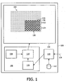
- Fig. 1 illustrates an embodiment of the invention.
- the figure illustrates a display device 100 comprising a display 102 with a plurality of pixels 104.
- the display 102 may be a liquid crystal display (LCD). However the invention is not limited to LCD displays.
- the display 102 may be for use in a direct view TV or monitor, for use in a rear projector or front projector, in a portable device such as PDA, mobile phone, or any other display application.
- the display may be a transmissive, reflective or transflective type.
- the pixels are indicated schematically by dots. In an area 120 the pixels are drawn using larger dots and circles for illustrating certain aspects of the invention.
- the sizes and positions of the dots do not relate to any physical dimensions of the actual pixels 104 of the display 102. Only some of the pixels 104 of the display 102 have been schematically drawn in fig. 1 . Normally the display 102 comprises many more pixels 104 than drawn in the figure.
- the display device 100 further comprises a source 110 for providing pixel parameter value data to be used in the display device 100 for rendering one or more images on the display 102.
- the display device 100 further comprises a driver 106 for driving the pixels 104 of the display 102.
- the driver 106 may comprise a means for driving 118, a value generator 116, and a means 108 for controlling an operating mode of the means for driving 118.
- the source 110 may obtain image and/or video data from an external source 114.
- the source 110 may comprise a video input, for example SCART or HDMI interface, or an analog (e.g. coaxial) video input.
- the source 110 may also obtain the image and/or video data from a storage medium 112.
- a storage medium 112 may comprise, for example, flash memory, a hard disk, an optical disc such as a DVD disc, or a video tape.
- the source 110 extracts pixel parameter values from the obtained image and/or video data and forwards these pixel parameter values to the driver 106. This extraction may include scaling to adapt the image and/or video data to the resolution and/or framerate of the display 102. Scaling may also be performed by the driver 106. In this case the pixel parameter values are the values after scaling in the driver 106.
- the pixels 104 are divided into a first group 122 (indicated by dark circles in the figure) and a second group 124 (indicated by white circles in the figure).
- the figure shows an example of how pixels may be allocated to the first group 122 and the second group 124 according to a checkerboard pattern.
- the driver 106 is constructed for supplying a first drive signal to a first pixel 126 which is one of the pixels out of the first group 122 and a second drive signal to a second pixel 128 which is one of the pixels out of the second group 124.
- the first pixel 126 and the second pixel 128 are neighboring pixels.
- the value generator 116 is arranged for generating a first upper value and a first lower value, wherein the first upper value and the first lower value together correspond to a first pixel value obtained from the source 110.
- the value generator is arranged for further generating a second upper value and a second lower value, wherein the second upper value and the second lower value together correspond to a second pixel value obtained from the source 110.
- These upper and lower values may be generated as explained above in relation to dark and bright sub-frames.
- the pixel values define values for a pixel, wherein a pixel value may be used to drive the luminance and/or color of a pixel.
- the pixel value controls the luminance of a sub-pixel, wherein the sub-pixel corresponds to a certain color, for example red, green, or blue.
- the means 118 for driving is arranged for driving the first pixel with the first lower value and driving the second pixel with the second upper value.
- the means 118 for driving may be implemented as a driver circuit in hardware and/or in the form of software, for example, as a controller or as a software module that is executed on a processor.
- the means 118 for driving is a part of the driver 106. It receives the upper and lower values from the value generator 116. Its operating mode may be controlled by the means 108 for controlling.
- the means 118 for driving controls the information content of the drive signals that are supplied to the pixels 104 based on the received upper and lower values and based on the operating mode.
- the means 118 for driving, the value generator 116 and/or the means 108 for controlling may be combined in one piece of hardware and/or one or more software modules.
- a means 108 for controlling an operating mode of the means for driving is provided.
- This means 108 for controlling an operating mode may be implemented, for example, as a controller or as a software module.
- the means 118 for driving drives the first pixel with the first lower value and drives the second pixel with the second upper value.
- the means 118 for driving drives the first pixel with the first upper value and drives the second pixel with the second lower value.
- the means 108 for controlling the operating mode is arranged for alternating between the first operating mode and the second operating mode.
- the means 108 for controlling the operating mode is arranged for alternating between the operating modes at a rate substantially half a frame rate of the display. Consequently, substantially after every second screen refresh, the operating mode is changed.
- the driver is arranged for driving the plurality of pixels 104 to render a sequence of images of a video sequence, wherein each image of the sequence of images is associated with a corresponding first pixel parameter value and a corresponding second pixel parameter.value, generated by the value generator 116.
- the means 108 for controlling the operating mode is arranged for causing the driver to apply both the first operating mode and the second operating mode to each image. This way, each image is rendered two times: in the first operating mode and in the second operating mode. This may be easily implemented if the frame rate of the display is substantially two times a frame rate of the video sequence.
- the means 108 for controlling the operating mode is arranged for successively applying the first operating mode to a first image of the video sequence, applying the second operating mode to the first image of the video sequence, applying the second operating mode to a second image of the video sequence, and applying the first operating mode to the second image of the video sequence, wherein the first image and the second image are sequential images of the video sequence.
- This pattern is repeated for the following images in the video sequence, so that an operating mode is applied two times before switching to the other operating mode.
- Some images are first rendered in the first operating mode and then in the second operating mode, whereas other images are first rendered in the second operating mode and then in the first operating mode. This may help prevent DC build-up to occur in the pixel's electrodes.
- substantially each pixel in the first one of the at least two groups of pixels is adjacent to at least one pixel in another one of the at least two groups of pixels.
- substantially each pixel in the second one of the at least two groups of pixels is adjacent to at least one pixel in another one of the at least two groups of pixels. This is, for example, the case in the illustrated area 120. More particularly, in the illustrated embodiment the adjacent pixels of a given pixel in both horizontal and vertical directions are in a different group than the given pixel. This may result in a checkerboard pattern.
- the adjacent pixels of a given pixel in either one of horizontal and vertical direction are not in the same group as the given pixel, but the adjacent pixels of the given pixel in another one of horizontal and vertical direction are in the same group as the given pixel. This may result in a line pattern. Line patterns and checkerboard patterns are discussed in more detail elsewhere in this description.
- the value generator 116 is arranged for further generating a third upper value and a third lower value.
- the third upper value and the third lower value together may correspond to a third pixel value.
- the first pixel parameter and the third pixel parameter may represent mutually different sub-pixels.
- the value generator (116) may be arranged for further generating a fourth upper value and a fourth lower value.
- the fourth upper value and the fourth lower value together may correspond to a fourth pixel value.
- the second pixel value and the fourth pixel value may represent mutually different sub-pixels.
- the first pixel value may represent a first sub-pixel of the first pixel 126
- the second pixel value may represent a first sub-pixel of the second pixel 1208
- the third pixel value may represent a second sub-pixel of the first pixel 126
- the fourth pixel value may represent a second sub-pixel of the second pixel 128.
- the first sub-pixel of the first pixel 126 and the first sub-pixel of the second pixel 128 have the same color, for example red.
- the second sub-pixel of the first pixel 126 and the second sub-pixel of the second pixel 128 may have a same color, for example blue.
- More sub-pixels may be defined having corresponding pixel parameters and corresponding to another color, for example green.
- Upper and lower values may be generated for these sub-pixels by the value generator and provided to the means for driving, wherein the latter will drive the pixels with the upper and/or lower values based on the operating mode.
- the means for driving may be arranged for driving the first pixel with the first lower value and the third upper value and driving the second pixel with the second upper value and the fourth lower value.
- the means for driving may be arranged for driving the first pixel with the first upper value and the third lower value and driving the second pixel with the second lower value and the fourth upper value.
- the display is a color sequential display.
- a color sequential display is arranged for rendering the different colors (e.g. red, green, or blue) of an image sequentially.
- color sequential displays are known in the art.
- a color sequential display may comprise a backlight modulated by an LCD panel.
- the backlight may quickly change its color according to a fixed, repetitive pattern, to enable rendering of a color image.
- the backlight may comprise different light sources (for example LED's) for the different colors, or it may comprise a white light source.
- a color filter wheel may be provided which is arranged for applying appropriate color filters sequentially. The color filter wheel and the white light source may be applied, for example, in a projection display.
- the value generator may be arranged for generating upper and lower values for at least three pixel color parameters of a pixel.
- the means for driving may be arranged for driving the pixel consecutively with the lower pixel color parameter values and for driving the pixel consecutively with the upper pixel color parameter values. Accordingly, the LCD experiences on average smaller jumps in the voltages applied to the electrodes of the pixel, which may result in reduced average latency.
- the means for driving may be arranged for driving the pixel consecutively with the lower pixel parameter values and for driving the pixel consecutively with the upper pixel parameter values. This way, the pixels need to switch less frequently from lower values to upper values and back.
- means are provided for identifying a first area of an image to be displayed and a second area of the image to be displayed, wherein the first area has more picture detail than the second area.
- This may be performed by means of image processing techniques. For example, the variance of luminance or of red, green, and/or blue parameters may be determined for an area, wherein a larger variance may be associated with more picture detail than a smaller variance.
- Other and more advanced methods of establishing the amount of picture detail in an area of the image are known by the skilled person. For example multi-scale image analysis techniques may be used.
- the area 120 of the display 102 corresponds to the area with more picture detail.
- the area of the display corresponding to the area of the image with less picture detail may be driven with the upper values and the lower values in phase.
- the driver 106 may be incorporated in a display device 100 comprising the display 102.
- the source 110 may be included in the display device 100.
- the source 110 and/or the storage means 112 may be provided in separate devices. It is also possible to implement the driver 106 as a separate device.
- the display 102 comprises a plurality of display pixels 104.
- Individual display pixels 126 have associated therewith at least one pixel parameter for controlling a luminance of at least a sub-pixel of the display pixel 126.
- the image may comprise a plurality of image pixels, individual image pixels having associated therewith a lower value and an upper value of the pixel parameter, the lower value being smaller than or equal to the upper value, the lower value and the upper value associated with an image pixel together corresponding to a pixel parameter, for example a luminance and/or color attribute of the image pixel.
- the lower value and the upper value may be selected for improving an off-axis image quality.
- the plurality of display pixels are divided into at least two groups 122 and 124 of display pixels, wherein the display pixels in the different groups 122 and 124 of display pixels are, preferably, evenly distributed over an area 120 of the display.
- the driver 106 is arranged for driving the plurality of display pixels to render the image by means of the means for driving 118.
- the means for driving 118 may be arranged for, in the first operating mode, driving respective display pixels 126 in a first one 122 of the at least two groups of display pixels 104 with the respective lower values of the respective image pixels, and for driving respective display pixels 128 in a second one 124 of the at least two groups of display pixels 104 with the respective upper values of the respective image pixels.
- the image to be displayed may be obtained after resampling an image obtained from the source 110 to.correspond to the pixel resolution of the display 102.
- a resolution converter or scaler (not shown) may be provided in the driver 106 and/or in the source 110.
- the means 118 for driving may be arranged for driving the respective display pixels 104 in the first one 122 of the at least two groups of display pixels 104 with the respective upper values of the respective image pixels and driving the respective display pixels 104 in the second one 124 of the at least two groups of display pixels with the respective lower values of the respective image pixels.
- the means 108 for controlling the operating mode may be arranged for alternating between the first operating mode and the second operating mode.
- a method of driving pixels 104 of a display in at least an area of the display, the pixels are divided into a first group and a second group.
- the method comprises supplying a first drive signal to a first pixel being one of the pixels out of the first group and a second drive signal to a second pixel being one of the pixels out of the second group, the first and second pixels being neighboring pixels.
- the method further comprises generating a first upper value and a first lower value, wherein the first upper value and the first lower value together correspond to a first pixel parameter value; and generating a second upper value and a second lower value, wherein the second upper value and the second lower value together correspond to a second pixel parameter value.
- the first pixel is driven with the first lower value and the second pixel is driven with the second upper value.
- At least two operating modes are provided: In the first operating mode, the method comprises driving the first pixel with the first lower value and driving the second pixel with the second upper value. In the second operating mode, the method comprises driving the first pixel with the first upper value and driving the second pixel with the second lower value. The method may comprise alternating between the first operating mode and the second operating mode.
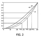
- the graph shown in fig. 2 schematically illustrates a suitable example of a relation between the normalized luminance (vertical axis) and the grey level signal (GLS, horizontal axis) for different examples of viewing angles of 0°, 30°, and 45° with respect to the normal (different curves marked 0°, 30°, and 45").
- the curves are provided for illustrating the concept of a gamma curve. The exact shapes of the curves may not be representative of actually manufactured displays. It can be seen that the off-axis luminance error (i.e.: the difference between the different curves) is relatively small at low and high drive values. So, here a situation is depicted where the distortion is more in the mid-grey level region and less at the extreme ends of the drive signal values. Such a situation occurs usually in vertical aligned (VA) panels.
- VA vertical aligned
- mid-grey drive values e.g. GLS f
- high and low drive values e.g. GLS 1 and GLS 2
- the resulting perceived luminance value corresponds to the original mid-grey luminance value GLS f or comes very close to it.
- An aim is that the distortion of the new resulting gamma curve may be reduced, especially for off-axis viewing angles.
- Both luminance levels e.g. GLS 1 and GLS 2
- GLS 1 and GLS 2 can be done via for example weight functions. Alternatively, for example a set of rules may be applied to distinguish between different ranges of luminance values. In another example, a look-up table is employed in which values of luminance GLS f are mapped into pairs of high and low drive values GLS 1 and GLS 2 .
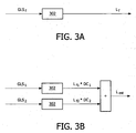
- Fig. 3 illustrates an example of an algorithm framework that may be used for choosing sub-frame luminance values.
- the use of two sub-frames is performed such that the overall Luminance value L f is preserved, as far as the viewer is concerned.
- L f L f 1 + l f 2 / 2 , wherein L f1 and L f2 correspond to the sub-frame luminance values, and wherein the duration of each of the sub-frames is 50% of the frame period.
- L f L f 1 + l f 2 / 2
- L f1 and L f2 correspond to the sub-frame luminance values
- the duration of each of the sub-frames is 50% of the frame period.
- this may not be the case, as explained below.
- Fig. 3A shows how a grey level signal (GLS f ) is used to drive a display 302, which results in a luminance L f .
- the display 302 is typically driven by grey level drive signals (GLS) having a certain bit precision (e.g. 8-bit precision), corresponding to a limited set of perceived luminance levels.
- GLS grey level drive signals
- Fig. 3B shows a sequential display of grey level signal GLS 1 having duty cycle DC 1 followed by grey level signal GLS 2 having duty cycle DC 2 .
- the luminance contribution when these grey level signals GLS 1 and GLS 2 are applied to the display 302 sequentially is L f1 * DC 1 and L 12 * DC 2 , respectively, wherein L f1 is the luminance of the display pixel 302 in response to grey level signal GLS 1 and L 12 is the luminance of the display pixel 302 in response to gray level signal GLS 2 .
- the estimated luminance L est may only be an estimate of the desired luminance L f which corresponds to gray level signal GLS f , for example because of quantization errors in selecting GLS 1 and GLS 2 .
- the value E should be set to any acceptable error level.
- E may be selected to be lower than the quantization error related to the display driver bit precision (or the perceived quantization error in multi-primary displays).
- a look-up table may be used that translates every grey level GLS f into a pair of two other grey levels GALS 1 and GLS 2 .
- the look-up table that translates GLS f into GLS 1 and GLS 2 can be calculated off-line; hence the generation of the LUT does not need to be implemented into the display, which saves computing power in the display.
- the generation of the LUT depends on the application of this versatile technique.
- One example is the minimization of the gamma curve distortion, which is outlined above.
- Another, related, example is minimization of color shift.
- the minimization of the gamma distortion uses only one single gamma function, which makes the method applicable to standard LCD panels.
- Other display technologies especially including TN, OCB, IPS, and FFS may also benefit from the principles underlying the above example.
- an image is displayed by using two frames, whereby one frame is bright and the second frame is dark. If these frames are displayed in temporal succession at for example 60 Hz it may cause flicker. Flicker is the perception of a modulation of the brightness. Therefore the image frame rate is increased to for example 120 Hz to reduce the flicker effect. This puts considerable requirements on the panel driving electronics and the liquid crystal (LC) response. However, by taking proper precautions discussed below, the described technology may also be applied at a low frame rate (such as 60 Hz), without introducing flicker. This allows the improvement of the viewing angle at a low frame rate. Motion blur may also be improved, for example if a dark frame succeeds a bright frame, and preferably using 120Hz driving.
- a low frame rate such as 60 Hz
- solutions are provided for reduced flicker and an improved off axis image quality by using a standard panel.
- Such an approach keeps implementation costs at a minimum.
- the flicker can be avoided by switching small pixels areas in opposite direction. This means one pixel (or a group of pixels) switches from a dark frame to a bright frame, whereas at the same time a neighboring pixel (or a group of pixels) switches from the bright frame to the dark frame. Both groups of pixels should be equally distributed across the screen in such a manner that the integral image (the perceived image frame, consisting of two sub-frames) does not flicker.
- the screen alters in a checkerboard fashion as depicted in fig. 4 .
- the tiles may have the size of one pixel.
- the tiles may also have the size of two adjacent pixels, or four adjacent pixels, e.g. a 2x2 square of pixels. Any size or shape of the tiles is allowable, however preferably the tiles are not too large in order to avoid the perception of artefacts.
- Fig. 4 illustrates an original image 702 (here a homogeneously grey image, for illustrational purpose), a bright sub-frame 704, a dark sub-frame 706, wherein the bright 704 and dark 706 sub-frames are derived from the original image 702 as set forth, and two modified sub-frames 708 and 710.
- the modified sub-frames show pieces of the bright sub-frame 704 and pieces of the dark sub-frame 706 in a checkerboard pattern, wherein the checkerboard pattern of the second modified sub-frame 710 has been inverted with respect to the first modified sub-frame 708.
- the screen alters in a line pattern as depicted in fig. 5 .
- Reference numerals 702-706 in fig. 5 point to items similar to those already described in relation to fig. 4 .
- the modified sub-frames 808 and 810 show vertical strips of pixels that are taken alternating from the dark sub-frame 706 and from the bright sub-frame 704.
- the line pattern of the second modified sub-frame 810 is inverted with respect to the first modified sub-frame 808.
- the width of the lines in pixels may be one or more pixels.
- the lines taken from the bright sub-frame 704 are as wide as the lines taken from the dark sub-frame 706.
- vertical lines are displayed, other line arrangements including horizontal or diagonal lines are also possible.
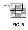
- one image frame is converted into two sub-frames and these sub-frames are shown in temporal succession. Consequently, the effective frame rate of the display is double the frame rate of a video sequence that is rendered.
- the information (the dark and the bright pixel values) on two adjacent pixels beside each other. These two display pixels together may thus render one image pixel. Although this reduces the image resolution, it may be a very useful technique to realize a gain in viewing angle. Because a standard display may be used at the normal refresh rate, this constitutes an embodiment that is particularly economic to realize.
- the principle is illustrated in fig. 6 . In this figure, bright and dark pixels are distributed in a checkerboard pattern, however, other arrangements are also possible. Two adjacent pixels 902 on the display may be used to render the dark and the bright values of the same image pixel.
- one of the sub-frames 708 and 710 is discarded and not rendered at all.
- rendering a video sequence for sequential image frames in the video sequence alternating either sub-frame 708 is rendered or sub-frame 710 is rendered. This has the advantage that the refresh rate of the display does not have to be doubled, and all of the pixels in the image frames do contribute to the end result, which increases the resolution and/or image quality of the rendering.
- the sequence of brigh and dark sub-frame pixel values is adapted to avoid a DC build-up in the LCD.
- the LCD's may be designed to employ an inversion scheme of plus, minus, plus, minus with time to avoid the DC build-up between electrodes within the LCD. This means, that the voltage applied to realize a certain colort in a pixel is positive in one frame and negative in the next, and so on, alternating between positive and negative voltage from frame to frame.
- the frames that are rendered are actually sub-frames having alternating high values and low values, the situation may occur that on the average, the positive voltage is in absolute value larger than the negative voltage. Also, the situation may occur that on the average, the negative voltage is in absolute value larger than the positive voltage. This may cause a DC build-up, which may be harmful for the LCD.
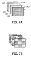
- the order of the sub-frames is slightly changed, as illustrated in fig. 7A and fig. 7B .
- Fig. 7A shows an order of rendering the sub-frames 1002, 1004, 1006, 1008 of sequential image frames 1010, 1012.
- the sign of the voltage applied to the electrodes regulating the pixels of the LCD has been indicated by means of a + sign or a - sign.
- the voltage follows a plus, minus, plus, minus scheme.
- the sub-frames are ordered dark, bright, bright, dark. This way, after a sequence of four images, one dark sub-frame and one bright sub-frame has been rendered in the "plus” mode. Also, one dark sub-frame and one bright sub-frame has been rendered in the "minus” mode. This way, on the average the DC component is zero or very close to zero.
- the sub-frames of a frame 1012 are rendered in inverse order compared to the sub-frames of the previous frame 1010. If the sub-frames 1002, 1004 of the previous frame are rendered in the order of first the dark sub-frame 1002, followed by the bright sub-frame 1004, then the sub-frames 1006, 1008 of the frame 1012 are rendered in the order of first the bright sub-frame 1006, followed by the dark sub-frame 1008. The next frame is rendered in the order of the frame 1010, and so on.
- Fig. 7B shows another ordering of the sub-frame rendering.
- the checkerboard pattern is used to divide the pixels into groups, wherein one group is for rendering portions of the dark sub-frame and the other group is for rendering portions of the bright sub-frame.
- Each group of pixels follows the rendering scheme that has been explained in relation to fig. 7A (dark, bright, bright, dark), however, whenever one group is rendering the dark values, the other group will render the bright values. This helps to reduce the flicker effect that may occur when rendering full bright subframes and full dark subframes.
- a line pattern or any other pattern may be used.
- the pixels in each group are uniformly distributed over the image, as explained before.
- each pixel may comprise a plurality of differently colored sub-pixels.
- the upper and lower luminance values and/or signal drive values may be determined separately, in the way discussed above.
- the pixels may be subdivided into the groups as discussed (e.g., a checkerboard pattern with one pixel in each checkerboard field), and each group may be driven alternating with upper drive values and lower drive values.
- the groups are defined on the sub-pixel level.
- the sub-pixels are individually assigned to one of the groups, wherein a sub-pixel represents a particular color of the pixel.
- the structure of the groups e.g., checkerboard pattern, line pattern
- the structure of the groups can be refined, making this structure even less visible and further reducing any possible artifact effect arising from the chosen pattern or the used inversion scheme.
- Fig. 8A and fig. 8B illustrate an embodiment wherein the checkerboard pattern is implemented at a sub-pixel level.
- the two figures show two sequential sub-frames are applied to a small portion of the display.
- Fig. 8A shows a diagram of a detail of a grid of pixels of a display.
- One pixel 1102 comprises a plurality of sub-pixels, in this case three sub-pixels are provided, each sub-pixel of the three sub-pixels can render a predetermined color, for example green (G), red (R), or blue (B).
- G green
- R red
- B blue
- the green sub-pixel (G) is driven with a lower value (of a dark sub-frame)
- the red sub-pixel (R) is driven with an upper value (of a bright sub-frame)
- the blue sub-pixel (B) is driven with an upper value of the bright sub-frame.
- the green sub-pixel (G) is driven with an upper value (of the bright sub-frame)
- the red sub-pixel (R) is driven with a lower value (of the dark sub-frame)
- the blue sub-pixel (B) is driven with a lower value of the dark sub-frame. This pattern is repeated, for example to form a checkerboard pattern.
- Fig. 8B shows the same portion of the display shown in fig. 8A , however the next sub-frame is shown.
- the role of each sub-pixel is exchanged: a sub-pixel displaying an upper value in fig. 8A is displaying a lower value in fig. 8B . This way the role of each sub-pixel is alternated for each sequential sub-frame that is rendered.
- LCD displays including, but not limited to, transflective, reflective, and transmissive displays, TV displays, mobile phone displays or PDA's.
- color sequential displays such as an RGB color sequential display
- each image that is to be rendered is separated in its color components (in this case RGB), to form a single color image frame for each color component.
- RGB color components
- These single color image frames are then displayed sequentially.
- Color sequential displays have some advantages, including the possibility to realize a higher resolution compared to a conventional panel at the same display size. Also, a higher possible transmittance may be realized (due to the omitted color filters). To avoid image flicker, such displays are often run at at least 180 Hz. Separating each color image in a bright and a dark frame can improve the off-axis image quality. This separation can be displayed spatially as well as temporally, as is further explained below.
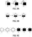
- Fig. 9A illustratively shows a pixel of a color sequential display which is driven to render a pixel of six sequential sub-frames, all relating to a single original image frame, indicatively shown by means of dark boxes (lower pixel values) and white boxes (upper pixel values), G, R, and B indicating green, red, and blue rendering, respectively.
- the successive rendering of upper pixel values and lower pixel values helps to improve the viewing angle of such systems.
- the pixels may be uniformly divided into groups, wherein the groups render the upper and lower pixel values at different times, i.e., when one group renders upper pixel values, the other group renders lower pixel values, and vice versa.
- the sequence upper, upper, lower, lower may be employed as set forth, in particular when using a display that follows a plus, minus, plus, minus electrode polarity inversion scheme.
- the frame rate (i.e., field rate) of the color sequential display is six times the frame rate of a video sequence to be rendered, because each frame of the video sequence is converted into six sub-frames as set forth.
- the pixel could be made up of two or more sub-pixels, which can be driven independently. This situation is shown in fig. 9B . In such a case, both the upper and lower drive values are rendered simultaneously, albeit spatially separated.
- two pixels of the display are used for rendering a single pixel of the image. Although this halves the resolution of the display, it is economic to realize as no special hardware is required.
- the pixels are first driven with their respective three upper RGB values, and then they are driven with their respective three lower RGB values. This could also be done in the other order, so first the lower three values followed by the upper three values. This way, the difference between successive drive values will, on the average, be smaller. This allows the liquid crystals to arrive at the desired transparency value more quickly, which allows to increase the duty cycle, and allows for longer backlight flashes. It also allows to increase the field rate and frame rate.
- the distribution of pixels of each group is performed also on the basis of the content of the image to be displayed.
- image areas having a large degree of picture detail may be rendered using the checkerboard pattern or the line pattern set forth herein.
- image areas having relatively little picture detail for example larger areas of approximately the same color, for example a blue sky, is rendered in the more traditional impulse driving method, wherein all pixels are driven with the upper values at the same time and all pixels are driven with the lower values at the same time. This could help to reduce artifacts further in some cases, for example at relatively low refresh rates. It is also possible to adapt the pattern of the even distribution of the groups to the level of picture detail.
- the invention also extends to computer programs, particularly computer programs on or in a carrier, adapted for putting the invention into practice.
- the program may be in the form of source code, object code, a code intermediate source and object code such as partially compiled form, or in any other form suitable for use in the implementation of the method according to the invention.
- a program may have many different architectural designs.
- a program code implementing the functionality of the method or system according to the invention may be subdivided into one or more subroutines. Many different ways to distribute the functionality among these subroutines will be apparent to the skilled person.
- the subroutines may be stored together in one executable file to form a self-contained program.
- Such an executable file may comprise computer executable instructions, for example processor instructions and/or interpreter instructions (e.g. Java interpreter instructions).
- one or more or all of the subroutines may be stored in at least one external library file and linked with a main program either statically or dynamically, e.g. at run-time.
- the main program contains at least one call to at least one of the subroutines.
- the subroutines may comprise function calls to each other.
- An embodiment relating to a computer program product comprises computer executable instructions corresponding to each of the processing steps of at least one of the methods set forth. These instructions may be subdivided into subroutines and/or be stored in one or more files that may be linked statically or dynamically.
- Another embodiment relating to a computer program product comprises computer executable instructions corresponding to each of the means of at least one of the systems and/or products set forth. These instructions may be subdivided into subroutines and/or be stored in one or more files that may be linked statically or dynamically.
- the carrier of a computer program may be any entity or device capable of carrying the program.
- the carrier may include a storage medium, such as a ROM, for example a CD ROM or a semiconductor ROM, or a magnetic recording medium, for example a floppy disc or hard disk.
- the carrier may be a transmissible carrier such as an electrical or optical signal, which may be conveyed via electrical or optical cable or by radio or other means.
- the carrier may be constituted by such cable or other device or means.
- the carrier may be an integrated circuit in which the program is embedded, the integrated circuit being adapted for performing, or for use in the performance of, the relevant method.
Landscapes
- Engineering & Computer Science (AREA)
- Chemical & Material Sciences (AREA)
- Crystallography & Structural Chemistry (AREA)
- Physics & Mathematics (AREA)
- Computer Hardware Design (AREA)
- General Physics & Mathematics (AREA)
- Theoretical Computer Science (AREA)
- Control Of Indicators Other Than Cathode Ray Tubes (AREA)
- Liquid Crystal Display Device Control (AREA)
- Liquid Crystal (AREA)
Claims (10)
- Pilote (106) destiné à commander des pixels (104) d'un dispositif d'affichage (102), dans lequel, dans au moins une zone (120) du dispositif d'affichage, les pixels sont divisés en un premier groupe et un second groupe ;
le pilote étant agencé pour commander la pluralité de pixels afin de rendre une séquence d'images d'une séquence vidéo, dans laquelle chaque image de la séquence d'images est associée à une première valeur de pixel correspondante et une deuxième valeur de pixel correspondante, la fréquence de trame du dispositif d'affichage étant sensiblement égale à deux fois la fréquence de trame de la séquence vidéo, de telle sorte que chaque image de la séquence vidéo comprend un premier et un second cadre d'affichage, afin de fournir un premier signal de commande à un premier pixel qui est l'un des pixels du premier groupe, et un second signal de commande à un deuxième pixel qui est l'un des pixels du second groupe, les premier et deuxième pixels étant des pixels adjacents et afin d'appliquer des tensions de commande au premier et au deuxième pixel qui alternent entre une tension positive et une tension négative, de trame en trame, pour la fréquence de trame du dispositif d'affichage ;
dans lequel le pilote (106) comprend :un générateur de valeur (116) agencé pour générer une première valeur supérieure et une première valeur inférieure, dans lequel la première valeur supérieure et la première valeur inférieure correspondent, ensemble, à la première valeur de pixel, le générateur de valeur étant agencé pour générer en outre une deuxième valeur supérieure et une deuxième valeur inférieure, dans lequel la deuxième valeur supérieure et la deuxième valeur inférieure correspondent, ensemble, à la deuxième valeur de pixel ;des organes (118) destinés à commander, dans un premier mode de fonctionnement, le premier pixel au moyen de la première valeur inférieure et à commander le deuxième pixel au moyen de la deuxième valeur supérieure, et, dans un second mode de fonctionnement, à commander le premier pixel au moyen de la première valeur supérieure et à commander le deuxième pixel au moyen de la deuxième valeur inférieure ; dans lequel le pilote comprenddes organes (108) servant à régler le mode de fonctionnement de telle sorte que le premier mode de fonctionnement alterne avec le second mode de fonctionnement et servant à provoquer l'application, par le pilote, à la fois du premier mode de fonctionnement et du second mode de fonctionnement à chaque image de la séquence vidéo,caractérisé en ce que les organes de réglage du mode de fonctionnement provoquent également l'application successive, par le pilote, du premier mode de fonctionnement à un premier cadre d'affichage d'une première image de la séquence vidéo, l'application du second mode de fonctionnement à un second cadre d'affichage de la première image de la séquence vidéo, l'application du second mode de fonctionnement à un premier cadre d'affichage de la seconde image de la séquence vidéo, et l'application du premier mode de fonctionnement au second cadre d'affichage de la seconde image de la séquence vidéo, dans lequel la première image et la seconde image sont des images séquentielles de la séquence vidéo, et dans lequel le premier cadre d'affichage de la première image est rendu avant le second cadre d'affichage de la première image, qui est rendu avant le premier cadre d'affichage de la seconde image, qui est rendu avant le second cadre d'affichage de la seconde image, de telle sorte que le premier mode de fonctionnement et le second mode de fonctionnement alternent à une fréquence égale à la moitié d'une fréquence de trame du dispositif d'affichage. - Pilote selon la revendication 1, dans lequel sensiblement chaque pixel dans le premier des au moins deux groupes de pixel est voisin d'au moins un pixel dans un autre des au moins deux groupes de pixels et sensiblement chaque pixel dans le second des au moins deux groupes de pixels est voisin d'au moins un pixel dans un autre des au moins deux groupes de pixels.
- Pilote selon la revendication 2, dans lequel les pixels voisins d'un pixel donné dans les directions horizontale et verticale ne se trouvent pas dans le même groupe que le pixel donné.
- Pilote selon la revendication 2, dans lequel les pixels voisins d'un pixel donné dans l'une ou l'autre des directions horizontale et verticale ne se trouvent pas dans le même groupe que le pixel donné, mais les pixels voisins du pixel donné dans une autre des directions horizontale et verticale se trouvent dans le même groupe que le pixel donné.
- Pilote selon la revendication 1,
comprenant en outre des organes agencés pour effectuer le traitement de l'image dans le but d'établir l'amplitude de la netteté de l'image dans des zones d'une image qui doit être affichée, et pour identifier une première zone et une seconde zone de l'image qui doit être affichée en se fondant sur l'amplitude de la netteté de l'image, de telle sorte que la première zone identifiée présente plus de netteté de l'image que la seconde zone identifiée ; dans lequel la zone de l'affichage comprenant les premier et second groupes de pixels correspond à la première zone de l'image présentant plus de netteté de l'image, et le pilote comprend en outre des organes, couplés aux dits organes destinés à identifier la première et la seconde zone, afin de commander en même temps, au moyen des valeurs supérieures ou des valeurs inférieures, tous les pixels dans la zone d'affichage correspondant à la seconde zone identifiée de l'image. - Dispositif d'affichage (100) comprenant un dispositif d'affichage (102) et le pilote (106) selon la revendication 1.
- Pilote selon la revendication 6, dans lequel les pixels comprennent des sous-pixels et dans lequel le générateur de valeur (116) est agencé de manière à générer également une troisième valeur supérieure et une troisième valeur inférieure, dans lequel la troisième valeur supérieure et la troisième valeur inférieure correspondent ensemble à une troisième valeur de pixel, dans lequel la première valeur de pixel et la troisième valeur de pixel représentent des sous-pixels différents les uns des autres au sein du même pixel ; et dans lequel le générateur de valeur (116) est agencé pour générer également une quatrième valeur supérieure et une quatrième valeur inférieure, dans lequel la quatrième valeur supérieure et la quatrième valeur inférieure correspondent, ensemble, à une quatrième valeur de pixel, dans lequel la deuxième valeur de pixel et la quatrième valeur de pixel représentent des sous-pixels différents les uns des autres au sein du même pixel, et dans lequel les organes de commande sont agencés de manière à commander, dans le premier mode de fonctionnement, le premier pixel au moyen de la première valeur inférieure et de la troisième valeur supérieure et à commander le deuxième pixel au moyen de la deuxième valeur supérieure et de la quatrième valeur inférieure, et dans lequel les organes de commande sont agencés de manière à commander, dans le second mode de fonctionnement, le premier pixel au moyen de la première valeur supérieure et de la troisième valeur inférieure et de commander le deuxième pixel au moyen de la deuxième valeur inférieure et de la quatrième valeur supérieure.
- Dispositif d'affichage selon la revendication 6, dans lequel l'affichage est un affichage séquentiel en couleur.
- Procédé de commande de pixels (104) d'un dispositif d'affichage (102), dans lequel, dans au moins une zone de l'affichage, les pixels sont divisés en un premier groupe et un second groupe ;
dans lequel le procédé comprend les étapes suivante
commander la pluralité de pixels afin de rendre une séquence d'images d'une séquence vidéo, dans lequel chaque image de la séquence d'images est associée à une première valeur de pixel correspondante et une deuxième valeur de pixel correspondante, la fréquence de trame du dispositif d'affichage étant sensiblement égale à deux fois la fréquence de trame de la séquence vidéo, de telle sorte que chaque image de la séquence vidéo comprend un premier et un second cadre d'affichage ;
fournir un premier signal de commande à un premier pixel qui est l'un des pixels du premier groupe, et un second signal de commande à un deuxième pixel qui est l'un des pixels du second groupe, les premier et deuxième pixels étant des pixels adjacents ;
dans lequel les tensions appliquées au premier et au deuxième pixel alternent entre une tension positive et une tension négative, de trame en trame, pour la fréquence de trame du dispositif d'affichage ;
la génération d'une première valeur supérieure et d'une première valeur inférieure, dans lequel la première valeur supérieure et la première valeur inférieure correspondent, ensemble, à la première valeur de pixel,
la génération d'une deuxième valeur supérieure et d'une deuxième valeur inférieure, dans lequel la deuxième valeur supérieure et la deuxième valeur inférieure correspondent, ensemble, à la deuxième valeur de pixel ;
commander, dans un premier mode de fonctionnement, le premier pixel au moyen de la première valeur inférieure et commander le deuxième pixel au moyen de la deuxième valeur supérieure, et, dans un second mode de fonctionnement, commander le premier pixel au moyen de la première valeur inférieure et commander le deuxième pixel au moyen de la deuxième valeur supérieure ;
régler le mode de fonctionnement de telle sorte que le premier mode de fonctionnement alterne avec le second mode de fonctionnement ; et
appliquer à la fois le premier mode de fonctionnement et le second mode de fonctionnement à chaque image de la séquence vidéo,
caractérisé en ce que le procédé comprend l'application successive du premier mode de fonctionnement à un premier cadre d'affichage d'une première image de la séquence vidéo, l'application du second mode de fonctionnement à un second cadre d'affichage de la première image de la séquence vidéo, l'application du second mode de fonctionnement à un premier cadre d'affichage de la seconde image de la séquence vidéo, et l'application du premier mode de fonctionnement au second cadre d'affichage de la seconde image de la séquence vidéo, dans lequel la première image et la seconde image sont des images séquentielles de la séquence vidéo, et dans lequel le premier cadre d'affichage de la première image est rendu avant le second cadre d'affichage de la première image, qui est rendu avant le premier cadre d'affichage de la seconde image, qui est rendu avant le second cadre d'affichage de la seconde image,
de telle sorte que le premier mode de fonctionnement et le second mode de fonctionnement alternent à une fréquence égale à la moitié d'une fréquence de trame du dispositif d'affichage. - Produit de programme informatique permettant d'afficher une image sur un dispositif d'affichage (102) comprenant un code logiciel conçu pour mettre en oeuvre le procédé selon la revendication 9.
Priority Applications (1)
| Application Number | Priority Date | Filing Date | Title |
|---|---|---|---|
| EP08847536.3A EP2218306B1 (fr) | 2007-11-08 | 2008-11-03 | Commande de pixels pour un dispositif d'affichage |
Applications Claiming Priority (3)
| Application Number | Priority Date | Filing Date | Title |
|---|---|---|---|
| EP07120268 | 2007-11-08 | ||
| EP08847536.3A EP2218306B1 (fr) | 2007-11-08 | 2008-11-03 | Commande de pixels pour un dispositif d'affichage |
| PCT/IB2008/054562 WO2009060372A2 (fr) | 2007-11-08 | 2008-11-03 | Commande de pixels pour un dispositif d'affichage |
Publications (2)
| Publication Number | Publication Date |
|---|---|
| EP2218306A2 EP2218306A2 (fr) | 2010-08-18 |
| EP2218306B1 true EP2218306B1 (fr) | 2016-10-12 |
Family
ID=40491076
Family Applications (1)
| Application Number | Title | Priority Date | Filing Date |
|---|---|---|---|
| EP08847536.3A Not-in-force EP2218306B1 (fr) | 2007-11-08 | 2008-11-03 | Commande de pixels pour un dispositif d'affichage |
Country Status (10)
| Country | Link |
|---|---|
| US (1) | US20100238203A1 (fr) |
| EP (1) | EP2218306B1 (fr) |
| JP (1) | JP2011504245A (fr) |
| KR (1) | KR20100096139A (fr) |
| CN (1) | CN101855665B (fr) |
| BR (1) | BRPI0819197A2 (fr) |
| MX (1) | MX2010004954A (fr) |
| RU (1) | RU2010123179A (fr) |
| TW (1) | TW200929132A (fr) |
| WO (1) | WO2009060372A2 (fr) |
Families Citing this family (35)
| Publication number | Priority date | Publication date | Assignee | Title |
|---|---|---|---|---|
| US8643595B2 (en) * | 2004-10-25 | 2014-02-04 | Sipix Imaging, Inc. | Electrophoretic display driving approaches |
| US8243013B1 (en) | 2007-05-03 | 2012-08-14 | Sipix Imaging, Inc. | Driving bistable displays |
| US20080303780A1 (en) | 2007-06-07 | 2008-12-11 | Sipix Imaging, Inc. | Driving methods and circuit for bi-stable displays |
| US9019318B2 (en) * | 2008-10-24 | 2015-04-28 | E Ink California, Llc | Driving methods for electrophoretic displays employing grey level waveforms |
| US9251736B2 (en) | 2009-01-30 | 2016-02-02 | E Ink California, Llc | Multiple voltage level driving for electrophoretic displays |
| US20100194789A1 (en) * | 2009-01-30 | 2010-08-05 | Craig Lin | Partial image update for electrophoretic displays |
| CN102460555B (zh) * | 2009-04-30 | 2014-01-01 | 夏普株式会社 | 显示控制装置及液晶显示装置 |
| US9460666B2 (en) * | 2009-05-11 | 2016-10-04 | E Ink California, Llc | Driving methods and waveforms for electrophoretic displays |
| US8576164B2 (en) * | 2009-10-26 | 2013-11-05 | Sipix Imaging, Inc. | Spatially combined waveforms for electrophoretic displays |
| US11049463B2 (en) * | 2010-01-15 | 2021-06-29 | E Ink California, Llc | Driving methods with variable frame time |
| US9224338B2 (en) * | 2010-03-08 | 2015-12-29 | E Ink California, Llc | Driving methods for electrophoretic displays |
| TWI507079B (zh) * | 2010-03-26 | 2015-11-01 | My Semi Inc | 發光二極體的驅動裝置與其驅動方法 |
| US9013394B2 (en) | 2010-06-04 | 2015-04-21 | E Ink California, Llc | Driving method for electrophoretic displays |
| TWI598672B (zh) | 2010-11-11 | 2017-09-11 | 希畢克斯幻像有限公司 | 電泳顯示器的驅動方法 |
| TWI412016B (zh) * | 2011-05-11 | 2013-10-11 | Au Optronics Corp | 液晶顯示裝置及其驅動方法 |
| WO2013019114A1 (fr) * | 2011-08-03 | 2013-02-07 | Tp Vision Holding B.V. | Télévision comportant une gradation en 2d pour un mode de visualisation en 3d |
| KR101885186B1 (ko) * | 2011-09-23 | 2018-08-07 | 삼성전자주식회사 | 공유 백 채널을 통한 데이터 전송 방법 및 데이터 전송을 위한 멀티 펑션 드라이버 회로 그리고 이를 채용한 디스플레이 구동 장치 |
| US20130169706A1 (en) * | 2011-12-28 | 2013-07-04 | Adam W. Harant | Methods for Measurement of Microdisplay Panel Optical Performance Parameters |
| JP2013186285A (ja) * | 2012-03-08 | 2013-09-19 | Panasonic Liquid Crystal Display Co Ltd | 液晶表示装置 |
| KR20130117525A (ko) * | 2012-04-18 | 2013-10-28 | 삼성디스플레이 주식회사 | 영상 표시 시스템 및 이의 구동방법 |
| GB2516637A (en) * | 2013-07-26 | 2015-02-04 | Sharp Kk | Display device and method of driving same |
| TWI550332B (zh) | 2013-10-07 | 2016-09-21 | 電子墨水加利福尼亞有限責任公司 | 用於彩色顯示裝置的驅動方法 |
| US10380931B2 (en) | 2013-10-07 | 2019-08-13 | E Ink California, Llc | Driving methods for color display device |
| US10726760B2 (en) | 2013-10-07 | 2020-07-28 | E Ink California, Llc | Driving methods to produce a mixed color state for an electrophoretic display |
| JP6346788B2 (ja) * | 2014-05-22 | 2018-06-20 | シャープ株式会社 | 液晶表示装置およびその制御方法 |
| US9728142B2 (en) * | 2015-07-15 | 2017-08-08 | Christie Digital Systems Usa, Inc. | Reduced blur, low flicker display system |
| CN104952412B (zh) * | 2015-07-15 | 2018-04-13 | 深圳市华星光电技术有限公司 | 液晶面板的驱动方法及驱动装置 |
| CN105096856B (zh) * | 2015-07-23 | 2018-03-20 | 深圳市华星光电技术有限公司 | 液晶面板的驱动方法及驱动装置 |
| TWI611392B (zh) * | 2015-09-17 | 2018-01-11 | 達意科技股份有限公司 | 彩色電泳式顯示裝置及其顯示驅動方法 |
| US10013908B2 (en) * | 2015-10-13 | 2018-07-03 | Shenzhen China Star Optoelectronics Technology Co., Ltd | Display devices and displaying methods |
| JP2020525813A (ja) * | 2017-06-22 | 2020-08-27 | コンパウンド フォトニクス ユー.エス. コーポレーション | ディスプレイ・デバイスを駆動するシステムおよび方法 |
| US11475841B2 (en) | 2019-08-22 | 2022-10-18 | Apple Inc. | Display circuitry including selectively-activated slew booster |
| TWI752550B (zh) * | 2020-07-13 | 2022-01-11 | 明基電通股份有限公司 | 顯示裝置 |
| KR20220019393A (ko) * | 2020-08-10 | 2022-02-17 | 삼성전자주식회사 | 디스플레이 장치 및 그 제어 방법 |
| JP2024143294A (ja) * | 2023-03-30 | 2024-10-11 | ソニーグループ株式会社 | 表示装置および表示方法、並びに、表示システム |
Citations (3)
| Publication number | Priority date | Publication date | Assignee | Title |
|---|---|---|---|---|
| EP0875881A2 (fr) * | 1997-04-30 | 1998-11-04 | SHARP Corporation | Modulateurs de lumière à matrice active, utilisation d'un modulateur de lumière à matrice active, et dispositif d'affichage |
| EP1818903A1 (fr) * | 2004-11-05 | 2007-08-15 | Sharp Kabushiki Kaisha | Appareil d'affichage à cristaux liquides et méthode pour piloter celui-ci |
| EP2056286A1 (fr) * | 2006-08-24 | 2009-05-06 | Sharp Kabushiki Kaisha | Dispositif d'affichage à cristaux liquides |
Family Cites Families (18)
| Publication number | Priority date | Publication date | Assignee | Title |
|---|---|---|---|---|
| WO1995001701A1 (fr) * | 1993-06-30 | 1995-01-12 | Philips Electronics N.V. | Systemes d'affichage a matrice et principes de fonctionnement de ces systemes |
| JP2003532148A (ja) * | 2000-04-26 | 2003-10-28 | ウルトラチップ インコーポレイテッド | 省電力lcd駆動方式 |
| TW502234B (en) * | 2001-05-21 | 2002-09-11 | Chi Mei Optoelectronics Corp | Sub-frame driving method |
| JP4044347B2 (ja) * | 2002-03-05 | 2008-02-06 | 松下電器産業株式会社 | 液晶表示装置の駆動方法 |
| JP2005215590A (ja) * | 2004-02-02 | 2005-08-11 | Matsushita Electric Ind Co Ltd | 液晶表示装置の駆動方法 |
| US20080272998A1 (en) * | 2004-07-16 | 2008-11-06 | Tomoya Yano | Image Display Device and Image Display Method |
| US20060114220A1 (en) * | 2004-11-01 | 2006-06-01 | Shih-Chung Wang | Method for controlling opeprations of a liquid crystal display to avoid flickering frames |
| JP2008076416A (ja) * | 2004-12-27 | 2008-04-03 | Sharp Corp | 表示パネルの駆動装置、表示パネル及びそれを備えた表示装置並びに表示パネルの駆動方法 |
| TWI256035B (en) * | 2004-12-31 | 2006-06-01 | Au Optronics Corp | Liquid crystal display with improved motion image quality and driving method therefor |
| KR20060089831A (ko) * | 2005-02-04 | 2006-08-09 | 삼성전자주식회사 | 표시 장치의 구동 장치 |
| TWI271695B (en) * | 2005-03-29 | 2007-01-21 | Chi Mei Optoelectronics Corp | Driving system for color display |
| JP4713225B2 (ja) * | 2005-05-27 | 2011-06-29 | シャープ株式会社 | 液晶表示装置 |
| KR100691324B1 (ko) * | 2005-07-22 | 2007-03-12 | 삼성전자주식회사 | 액정 디스플레이장치 |
| JP4600219B2 (ja) * | 2005-08-31 | 2010-12-15 | カシオ計算機株式会社 | 液晶表示装置の駆動方法 |
| JP4720408B2 (ja) * | 2005-09-30 | 2011-07-13 | カシオ計算機株式会社 | 液晶表示素子の駆動方法及び液晶表示装置 |
| TWI449009B (zh) * | 2005-12-02 | 2014-08-11 | Semiconductor Energy Lab | 顯示裝置和使用該顯示裝置的電子裝置 |
| KR20080054190A (ko) * | 2006-12-12 | 2008-06-17 | 삼성전자주식회사 | 표시장치 및 이의 구동방법 |
| US9024966B2 (en) * | 2007-09-07 | 2015-05-05 | Qualcomm Incorporated | Video blending using time-averaged color keys |
-
2008
- 2008-11-03 MX MX2010004954A patent/MX2010004954A/es not_active Application Discontinuation
- 2008-11-03 EP EP08847536.3A patent/EP2218306B1/fr not_active Not-in-force
- 2008-11-03 WO PCT/IB2008/054562 patent/WO2009060372A2/fr active Application Filing
- 2008-11-03 CN CN2008801152466A patent/CN101855665B/zh active Active
- 2008-11-03 JP JP2010532690A patent/JP2011504245A/ja active Pending
- 2008-11-03 BR BRPI0819197 patent/BRPI0819197A2/pt not_active IP Right Cessation
- 2008-11-03 KR KR1020107012465A patent/KR20100096139A/ko not_active Application Discontinuation
- 2008-11-03 US US12/741,049 patent/US20100238203A1/en not_active Abandoned
- 2008-11-03 RU RU2010123179/07A patent/RU2010123179A/ru not_active Application Discontinuation
- 2008-11-06 TW TW097142881A patent/TW200929132A/zh unknown
Patent Citations (3)
| Publication number | Priority date | Publication date | Assignee | Title |
|---|---|---|---|---|
| EP0875881A2 (fr) * | 1997-04-30 | 1998-11-04 | SHARP Corporation | Modulateurs de lumière à matrice active, utilisation d'un modulateur de lumière à matrice active, et dispositif d'affichage |
| EP1818903A1 (fr) * | 2004-11-05 | 2007-08-15 | Sharp Kabushiki Kaisha | Appareil d'affichage à cristaux liquides et méthode pour piloter celui-ci |
| EP2056286A1 (fr) * | 2006-08-24 | 2009-05-06 | Sharp Kabushiki Kaisha | Dispositif d'affichage à cristaux liquides |
Also Published As
| Publication number | Publication date |
|---|---|
| EP2218306A2 (fr) | 2010-08-18 |
| MX2010004954A (es) | 2010-05-14 |
| CN101855665A (zh) | 2010-10-06 |
| US20100238203A1 (en) | 2010-09-23 |
| RU2010123179A (ru) | 2011-12-20 |
| CN101855665B (zh) | 2013-03-27 |
| WO2009060372A2 (fr) | 2009-05-14 |
| KR20100096139A (ko) | 2010-09-01 |
| WO2009060372A3 (fr) | 2009-07-02 |
| JP2011504245A (ja) | 2011-02-03 |
| BRPI0819197A2 (pt) | 2015-05-05 |
| TW200929132A (en) | 2009-07-01 |
Similar Documents
| Publication | Publication Date | Title |
|---|---|---|
| EP2218306B1 (fr) | Commande de pixels pour un dispositif d'affichage | |
| US8115728B2 (en) | Image display device with reduced flickering and blur | |
| US6970148B2 (en) | Image display method | |
| EP1927974B1 (fr) | Affichage à cristaux liquides doté de rétroéclairage adaptatif | |
| US8648780B2 (en) | Motion adaptive black data insertion | |
| US8704744B2 (en) | Systems and methods for temporal subpixel rendering of image data | |
| US5479188A (en) | Method for driving liquid crystal display panel, with reduced flicker and with no sticking | |
| US20080198127A1 (en) | Display Apparatus | |
| JPWO2009054223A1 (ja) | 画像表示装置 | |
| JP2011514544A (ja) | ディスプレイの制御 | |
| JP3902031B2 (ja) | 液晶表示装置の駆動方法 | |
| JP2007225861A (ja) | 液晶表示装置 | |
| US6961379B2 (en) | Method for processing video pictures and apparatus for processing video pictures | |
| CN110827733B (zh) | 用于显示面板的显示方法与显示设备 | |
| KR20070067815A (ko) | 액정 표시부를 위한 영상 처리 장치 및 방법 | |
| US10068535B2 (en) | Display apparatus and driving method thereof | |
| US20110310136A1 (en) | Liquid crystal display and driving method thereof | |
| EP2109094A1 (fr) | Contrôle d'inversion LCD | |
| JP2008299270A (ja) | 表示装置の駆動装置、電子機器 | |
| JP6701147B2 (ja) | 液晶駆動装置、画像表示装置、液晶駆動方法および液晶駆動プログラム | |
| JP2008145909A (ja) | 液晶表示装置 | |
| JP2008304661A (ja) | 表示装置および表示方法 | |
| JP2009237323A (ja) | 液晶表示装置 | |
| WO2022030133A1 (fr) | Circuit d'attaque | |
| JP2011158645A (ja) | 液晶表示装置 |
Legal Events
| Date | Code | Title | Description |
|---|---|---|---|
| PUAI | Public reference made under article 153(3) epc to a published international application that has entered the european phase |
Free format text: ORIGINAL CODE: 0009012 |
|
| 17P | Request for examination filed |
Effective date: 20100608 |
|
| AK | Designated contracting states |
Kind code of ref document: A2 Designated state(s): AT BE BG CH CY CZ DE DK EE ES FI FR GB GR HR HU IE IS IT LI LT LU LV MC MT NL NO PL PT RO SE SI SK TR |
|
| AX | Request for extension of the european patent |
Extension state: AL BA MK RS |
|
| 17Q | First examination report despatched |
Effective date: 20101004 |
|
| DAX | Request for extension of the european patent (deleted) | ||
| RAP1 | Party data changed (applicant data changed or rights of an application transferred) |
Owner name: TP VISION HOLDING B.V. |
|
| RAP1 | Party data changed (applicant data changed or rights of an application transferred) |
Owner name: TP VISION HOLDING B.V. |
|
| REG | Reference to a national code |
Ref country code: DE Ref legal event code: R079 Ref document number: 602008046828 Country of ref document: DE Free format text: PREVIOUS MAIN CLASS: H05B0033080000 Ipc: G09G0003360000 |
|
| GRAP | Despatch of communication of intention to grant a patent |
Free format text: ORIGINAL CODE: EPIDOSNIGR1 |
|
| INTG | Intention to grant announced |
Effective date: 20160513 |
|
| RIC1 | Information provided on ipc code assigned before grant |
Ipc: G09G 3/36 20060101AFI20160429BHEP |
|
| RIN1 | Information on inventor provided before grant (corrected) |
Inventor name: BUDZELAAR, FRANCISCUS P. M. Inventor name: LANGENDIJK, ERNO H. A. Inventor name: STROEMER, JAN F. Inventor name: BELIK, OLEG Inventor name: DESSAUD, NATHALIE M. D. |
|
| GRAS | Grant fee paid |
Free format text: ORIGINAL CODE: EPIDOSNIGR3 |
|
| GRAA | (expected) grant |
Free format text: ORIGINAL CODE: 0009210 |
|
| AK | Designated contracting states |
Kind code of ref document: B1 Designated state(s): AT BE BG CH CY CZ DE DK EE ES FI FR GB GR HR HU IE IS IT LI LT LU LV MC MT NL NO PL PT RO SE SI SK TR |
|
| REG | Reference to a national code |
Ref country code: GB Ref legal event code: FG4D |
|
| REG | Reference to a national code |
Ref country code: CH Ref legal event code: EP |
|
| REG | Reference to a national code |
Ref country code: AT Ref legal event code: REF Ref document number: 837133 Country of ref document: AT Kind code of ref document: T Effective date: 20161015 |
|
| REG | Reference to a national code |
Ref country code: FR Ref legal event code: PLFP Year of fee payment: 9 |
|
| REG | Reference to a national code |
Ref country code: IE Ref legal event code: FG4D |
|
| REG | Reference to a national code |
Ref country code: DE Ref legal event code: R096 Ref document number: 602008046828 Country of ref document: DE |
|
| REG | Reference to a national code |
Ref country code: LT Ref legal event code: MG4D |
|
| REG | Reference to a national code |
Ref country code: NL Ref legal event code: MP Effective date: 20161012 |
|
| PG25 | Lapsed in a contracting state [announced via postgrant information from national office to epo] |
Ref country code: LV Free format text: LAPSE BECAUSE OF FAILURE TO SUBMIT A TRANSLATION OF THE DESCRIPTION OR TO PAY THE FEE WITHIN THE PRESCRIBED TIME-LIMIT Effective date: 20161012 Ref country code: BE Free format text: LAPSE BECAUSE OF NON-PAYMENT OF DUE FEES Effective date: 20161130 |
|
| REG | Reference to a national code |
Ref country code: AT Ref legal event code: MK05 Ref document number: 837133 Country of ref document: AT Kind code of ref document: T Effective date: 20161012 |
|
| PG25 | Lapsed in a contracting state [announced via postgrant information from national office to epo] |
Ref country code: LT Free format text: LAPSE BECAUSE OF FAILURE TO SUBMIT A TRANSLATION OF THE DESCRIPTION OR TO PAY THE FEE WITHIN THE PRESCRIBED TIME-LIMIT Effective date: 20161012 Ref country code: SE Free format text: LAPSE BECAUSE OF FAILURE TO SUBMIT A TRANSLATION OF THE DESCRIPTION OR TO PAY THE FEE WITHIN THE PRESCRIBED TIME-LIMIT Effective date: 20161012 Ref country code: GR Free format text: LAPSE BECAUSE OF FAILURE TO SUBMIT A TRANSLATION OF THE DESCRIPTION OR TO PAY THE FEE WITHIN THE PRESCRIBED TIME-LIMIT Effective date: 20170113 Ref country code: NO Free format text: LAPSE BECAUSE OF FAILURE TO SUBMIT A TRANSLATION OF THE DESCRIPTION OR TO PAY THE FEE WITHIN THE PRESCRIBED TIME-LIMIT Effective date: 20170112 |
|
| PG25 | Lapsed in a contracting state [announced via postgrant information from national office to epo] |
Ref country code: HR Free format text: LAPSE BECAUSE OF FAILURE TO SUBMIT A TRANSLATION OF THE DESCRIPTION OR TO PAY THE FEE WITHIN THE PRESCRIBED TIME-LIMIT Effective date: 20161012 Ref country code: AT Free format text: LAPSE BECAUSE OF FAILURE TO SUBMIT A TRANSLATION OF THE DESCRIPTION OR TO PAY THE FEE WITHIN THE PRESCRIBED TIME-LIMIT Effective date: 20161012 Ref country code: ES Free format text: LAPSE BECAUSE OF FAILURE TO SUBMIT A TRANSLATION OF THE DESCRIPTION OR TO PAY THE FEE WITHIN THE PRESCRIBED TIME-LIMIT Effective date: 20161012 Ref country code: BE Free format text: LAPSE BECAUSE OF FAILURE TO SUBMIT A TRANSLATION OF THE DESCRIPTION OR TO PAY THE FEE WITHIN THE PRESCRIBED TIME-LIMIT Effective date: 20161012 Ref country code: PT Free format text: LAPSE BECAUSE OF FAILURE TO SUBMIT A TRANSLATION OF THE DESCRIPTION OR TO PAY THE FEE WITHIN THE PRESCRIBED TIME-LIMIT Effective date: 20170213 Ref country code: NL Free format text: LAPSE BECAUSE OF FAILURE TO SUBMIT A TRANSLATION OF THE DESCRIPTION OR TO PAY THE FEE WITHIN THE PRESCRIBED TIME-LIMIT Effective date: 20161012 Ref country code: PL Free format text: LAPSE BECAUSE OF FAILURE TO SUBMIT A TRANSLATION OF THE DESCRIPTION OR TO PAY THE FEE WITHIN THE PRESCRIBED TIME-LIMIT Effective date: 20161012 Ref country code: FI Free format text: LAPSE BECAUSE OF FAILURE TO SUBMIT A TRANSLATION OF THE DESCRIPTION OR TO PAY THE FEE WITHIN THE PRESCRIBED TIME-LIMIT Effective date: 20161012 Ref country code: IS Free format text: LAPSE BECAUSE OF FAILURE TO SUBMIT A TRANSLATION OF THE DESCRIPTION OR TO PAY THE FEE WITHIN THE PRESCRIBED TIME-LIMIT Effective date: 20170212 |
|
| REG | Reference to a national code |
Ref country code: CH Ref legal event code: PL |
|
| REG | Reference to a national code |
Ref country code: DE Ref legal event code: R097 Ref document number: 602008046828 Country of ref document: DE |
|
| PG25 | Lapsed in a contracting state [announced via postgrant information from national office to epo] |
Ref country code: CH Free format text: LAPSE BECAUSE OF NON-PAYMENT OF DUE FEES Effective date: 20161130 Ref country code: LI Free format text: LAPSE BECAUSE OF NON-PAYMENT OF DUE FEES Effective date: 20161130 Ref country code: MC Free format text: LAPSE BECAUSE OF FAILURE TO SUBMIT A TRANSLATION OF THE DESCRIPTION OR TO PAY THE FEE WITHIN THE PRESCRIBED TIME-LIMIT Effective date: 20161012 Ref country code: EE Free format text: LAPSE BECAUSE OF FAILURE TO SUBMIT A TRANSLATION OF THE DESCRIPTION OR TO PAY THE FEE WITHIN THE PRESCRIBED TIME-LIMIT Effective date: 20161012 Ref country code: CZ Free format text: LAPSE BECAUSE OF FAILURE TO SUBMIT A TRANSLATION OF THE DESCRIPTION OR TO PAY THE FEE WITHIN THE PRESCRIBED TIME-LIMIT Effective date: 20161012 Ref country code: SK Free format text: LAPSE BECAUSE OF FAILURE TO SUBMIT A TRANSLATION OF THE DESCRIPTION OR TO PAY THE FEE WITHIN THE PRESCRIBED TIME-LIMIT Effective date: 20161012 Ref country code: RO Free format text: LAPSE BECAUSE OF FAILURE TO SUBMIT A TRANSLATION OF THE DESCRIPTION OR TO PAY THE FEE WITHIN THE PRESCRIBED TIME-LIMIT Effective date: 20161012 Ref country code: DK Free format text: LAPSE BECAUSE OF FAILURE TO SUBMIT A TRANSLATION OF THE DESCRIPTION OR TO PAY THE FEE WITHIN THE PRESCRIBED TIME-LIMIT Effective date: 20161012 |
|
| PLBE | No opposition filed within time limit |
Free format text: ORIGINAL CODE: 0009261 |
|
| STAA | Information on the status of an ep patent application or granted ep patent |
Free format text: STATUS: NO OPPOSITION FILED WITHIN TIME LIMIT |
|
| REG | Reference to a national code |
Ref country code: IE Ref legal event code: MM4A |
|
| PG25 | Lapsed in a contracting state [announced via postgrant information from national office to epo] |
Ref country code: BG Free format text: LAPSE BECAUSE OF FAILURE TO SUBMIT A TRANSLATION OF THE DESCRIPTION OR TO PAY THE FEE WITHIN THE PRESCRIBED TIME-LIMIT Effective date: 20170112 Ref country code: IT Free format text: LAPSE BECAUSE OF FAILURE TO SUBMIT A TRANSLATION OF THE DESCRIPTION OR TO PAY THE FEE WITHIN THE PRESCRIBED TIME-LIMIT Effective date: 20161012 |
|
| 26N | No opposition filed |
Effective date: 20170713 |
|
| PG25 | Lapsed in a contracting state [announced via postgrant information from national office to epo] |
Ref country code: LU Free format text: LAPSE BECAUSE OF NON-PAYMENT OF DUE FEES Effective date: 20161130 |
|
| REG | Reference to a national code |
Ref country code: FR Ref legal event code: PLFP Year of fee payment: 10 |
|
| PG25 | Lapsed in a contracting state [announced via postgrant information from national office to epo] |
Ref country code: SI Free format text: LAPSE BECAUSE OF FAILURE TO SUBMIT A TRANSLATION OF THE DESCRIPTION OR TO PAY THE FEE WITHIN THE PRESCRIBED TIME-LIMIT Effective date: 20161012 Ref country code: IE Free format text: LAPSE BECAUSE OF NON-PAYMENT OF DUE FEES Effective date: 20161103 |
|
| PG25 | Lapsed in a contracting state [announced via postgrant information from national office to epo] |
Ref country code: CY Free format text: LAPSE BECAUSE OF FAILURE TO SUBMIT A TRANSLATION OF THE DESCRIPTION OR TO PAY THE FEE WITHIN THE PRESCRIBED TIME-LIMIT Effective date: 20161012 Ref country code: HU Free format text: LAPSE BECAUSE OF FAILURE TO SUBMIT A TRANSLATION OF THE DESCRIPTION OR TO PAY THE FEE WITHIN THE PRESCRIBED TIME-LIMIT; INVALID AB INITIO Effective date: 20081103 |
|
| PG25 | Lapsed in a contracting state [announced via postgrant information from national office to epo] |
Ref country code: TR Free format text: LAPSE BECAUSE OF FAILURE TO SUBMIT A TRANSLATION OF THE DESCRIPTION OR TO PAY THE FEE WITHIN THE PRESCRIBED TIME-LIMIT Effective date: 20161012 |
|
| PG25 | Lapsed in a contracting state [announced via postgrant information from national office to epo] |
Ref country code: MT Free format text: LAPSE BECAUSE OF NON-PAYMENT OF DUE FEES Effective date: 20161103 |
|
| REG | Reference to a national code |
Ref country code: FR Ref legal event code: PLFP Year of fee payment: 11 |
|
| REG | Reference to a national code |
Ref country code: GB Ref legal event code: 732E Free format text: REGISTERED BETWEEN 20210708 AND 20210714 |
|
| REG | Reference to a national code |
Ref country code: DE Ref legal event code: R081 Ref document number: 602008046828 Country of ref document: DE Owner name: TOP VICTORY INVESTMENTS LIMITED, KWUN TONG, HK Free format text: FORMER OWNER: TP VISION HOLDING B.V., AMSTERDAM, NL Ref country code: DE Ref legal event code: R082 Ref document number: 602008046828 Country of ref document: DE |
|
| PGFP | Annual fee paid to national office [announced via postgrant information from national office to epo] |
Ref country code: GB Payment date: 20211013 Year of fee payment: 14 Ref country code: DE Payment date: 20211014 Year of fee payment: 14 |
|
| PGFP | Annual fee paid to national office [announced via postgrant information from national office to epo] |
Ref country code: FR Payment date: 20211013 Year of fee payment: 14 |
|
| REG | Reference to a national code |
Ref country code: DE Ref legal event code: R119 Ref document number: 602008046828 Country of ref document: DE |
|
| GBPC | Gb: european patent ceased through non-payment of renewal fee |
Effective date: 20221103 |
|
| PG25 | Lapsed in a contracting state [announced via postgrant information from national office to epo] |
Ref country code: GB Free format text: LAPSE BECAUSE OF NON-PAYMENT OF DUE FEES Effective date: 20221103 Ref country code: DE Free format text: LAPSE BECAUSE OF NON-PAYMENT OF DUE FEES Effective date: 20230601 |
|
| PG25 | Lapsed in a contracting state [announced via postgrant information from national office to epo] |
Ref country code: FR Free format text: LAPSE BECAUSE OF NON-PAYMENT OF DUE FEES Effective date: 20221130 |