EP2216639A1 - Blood fluidity measurement apparatus and blood fluidity measurement method - Google Patents
Blood fluidity measurement apparatus and blood fluidity measurement method Download PDFInfo
- Publication number
- EP2216639A1 EP2216639A1 EP08853229A EP08853229A EP2216639A1 EP 2216639 A1 EP2216639 A1 EP 2216639A1 EP 08853229 A EP08853229 A EP 08853229A EP 08853229 A EP08853229 A EP 08853229A EP 2216639 A1 EP2216639 A1 EP 2216639A1
- Authority
- EP
- European Patent Office
- Prior art keywords
- blood
- deformability
- velocity
- fluidity
- cells
- Prior art date
- Legal status (The legal status is an assumption and is not a legal conclusion. Google has not performed a legal analysis and makes no representation as to the accuracy of the status listed.)
- Withdrawn
Links
Images


Classifications
-
- G—PHYSICS
- G01—MEASURING; TESTING
- G01N—INVESTIGATING OR ANALYSING MATERIALS BY DETERMINING THEIR CHEMICAL OR PHYSICAL PROPERTIES
- G01N11/00—Investigating flow properties of materials, e.g. viscosity, plasticity; Analysing materials by determining flow properties
- G01N11/02—Investigating flow properties of materials, e.g. viscosity, plasticity; Analysing materials by determining flow properties by measuring flow of the material
- G01N11/04—Investigating flow properties of materials, e.g. viscosity, plasticity; Analysing materials by determining flow properties by measuring flow of the material through a restricted passage, e.g. tube, aperture
-
- G—PHYSICS
- G01—MEASURING; TESTING
- G01F—MEASURING VOLUME, VOLUME FLOW, MASS FLOW OR LIQUID LEVEL; METERING BY VOLUME
- G01F3/00—Measuring the volume flow of fluids or fluent solid material wherein the fluid passes through the meter in successive and more or less isolated quantities, the meter being driven by the flow
- G01F3/36—Measuring the volume flow of fluids or fluent solid material wherein the fluid passes through the meter in successive and more or less isolated quantities, the meter being driven by the flow with stationary measuring chambers having constant volume during measurement
-
- G—PHYSICS
- G01—MEASURING; TESTING
- G01N—INVESTIGATING OR ANALYSING MATERIALS BY DETERMINING THEIR CHEMICAL OR PHYSICAL PROPERTIES
- G01N15/00—Investigating characteristics of particles; Investigating permeability, pore-volume or surface-area of porous materials
- G01N15/10—Investigating individual particles
- G01N15/14—Optical investigation techniques, e.g. flow cytometry
- G01N15/1429—Signal processing
- G01N15/1433—Signal processing using image recognition
-
- G—PHYSICS
- G01—MEASURING; TESTING
- G01N—INVESTIGATING OR ANALYSING MATERIALS BY DETERMINING THEIR CHEMICAL OR PHYSICAL PROPERTIES
- G01N33/00—Investigating or analysing materials by specific methods not covered by groups G01N1/00 - G01N31/00
- G01N33/48—Biological material, e.g. blood, urine; Haemocytometers
- G01N33/483—Physical analysis of biological material
- G01N33/487—Physical analysis of biological material of liquid biological material
- G01N33/49—Blood
-
- G—PHYSICS
- G06—COMPUTING OR CALCULATING; COUNTING
- G06T—IMAGE DATA PROCESSING OR GENERATION, IN GENERAL
- G06T7/00—Image analysis
- G06T7/20—Analysis of motion
- G06T7/215—Motion-based segmentation
-
- G—PHYSICS
- G01—MEASURING; TESTING
- G01N—INVESTIGATING OR ANALYSING MATERIALS BY DETERMINING THEIR CHEMICAL OR PHYSICAL PROPERTIES
- G01N15/00—Investigating characteristics of particles; Investigating permeability, pore-volume or surface-area of porous materials
- G01N15/10—Investigating individual particles
- G01N2015/1027—Determining speed or velocity of a particle
-
- G—PHYSICS
- G01—MEASURING; TESTING
- G01N—INVESTIGATING OR ANALYSING MATERIALS BY DETERMINING THEIR CHEMICAL OR PHYSICAL PROPERTIES
- G01N15/00—Investigating characteristics of particles; Investigating permeability, pore-volume or surface-area of porous materials
- G01N15/10—Investigating individual particles
- G01N15/14—Optical investigation techniques, e.g. flow cytometry
- G01N2015/1493—Particle size
- G01N2015/1495—Deformation of particles
-
- G—PHYSICS
- G06—COMPUTING OR CALCULATING; COUNTING
- G06T—IMAGE DATA PROCESSING OR GENERATION, IN GENERAL
- G06T2207/00—Indexing scheme for image analysis or image enhancement
- G06T2207/30—Subject of image; Context of image processing
- G06T2207/30004—Biomedical image processing
- G06T2207/30101—Blood vessel; Artery; Vein; Vascular
- G06T2207/30104—Vascular flow; Blood flow; Perfusion
Definitions
- the present invention relates to a blood fluidity measurement apparatus and a blood fluidity measurement method.
- the fluidity is also called as the degree of smoothness, and it means that the higher the fluidity or the smoothness is the better in health.
- Patent Document 2 a method for capturing movements of white blood cells in an adherence phenomenon in which white blood cells adhere to blood veins which is particular to white blood cells. In this method, a moving velocity and so on ofblood cells in a process to adhere to blood veins can be calculated by digital processing the image capturing the movement of the white blood cell.
- Patent Document 1 Japanese Patent No. 2685544
- Patent Document 2 Japanese Patent Application Publication No. 2001-264318
- Non Patent Document 1 Tsutomu Tinikawa et al. "Visualization and Observation of Deformation of Human Red Blood Cell Passing Through a Micro-channel Array as a Model of Human blood Capillary", pages 84-91, December 2005, Vol.25 No.12 Transaction of the Visualization Society of Japan .
- Patent Document 1 it is not possible to make a quantitative evaluation for the blood fluidity, especially for deformability of blood.
- Patent Document 2 regarding to the movement of white blood cells, it is not possible to quantify the movement of white blood cells either.
- the operation of the quantification is time consuming because the operation is performed each by each for each blood cell although the quantification of the deformability is tried.
- the present invention has been achieved in consideration of the above problems, and it is an object of the invention to provide a blood fluidity measurement apparatus and a blood fluidity measurement method, which can evaluate the deformability ofblood cells which is a representative parameter of blood fluidity, in a short time.
- a blood fluidity measurement apparatus which measures a blood fluidity by flowing blood in a plurality of gates each of which is formed to be narrower than a blood diameter, comprises:
- the invention described in Claim 2 is the blood fluidity measurement apparatus described in Claim 1, characterized in that:
- the invention described in Claim 3 is the blood fluidity measurement apparatus described in Claim 1, characterized in that:
- the invention described in Claim 4 is the blood fluidity measurement apparatus described in Claim 1, characterized in that:
- the invention described in Claim 5 is the blood fluidity measurement apparatus described in Claim 3 or Claim 4, characterized in that:
- the invention described in Claim 6 is a blood fluidity measurement apparatus described in Claim 3 or Claim 4, characterized in that
- the invention described in Claim 7 is a blood fluidity measurement method characterized in that the method comprises measuring a blood fluidity using the blood fluidity measurement apparatus described in any one of Claim 1 through 6.
- an imaging means which takes an image of blood flow in each of any two areas of an internal area, an inlet area and an outlet area of the gate, or in each internal area of the plurality of the gates; a velocity calculation means which calculates a velocity ofblood cells in the blood by the image taken by the imaging means; and a deformability calculation means which calculates a deformability of blood cells as a blood fluidity, by the velocity, therefore, in case of a timing when an image is taken by the imaging means, deformability of all the blood included in the image can be calculated arbitrarily as blood fluidity from the velocity.
- the quantification operation is performed for each blood cell individually, the quantification of deformability ofblood cells can be performed in a shorter time.
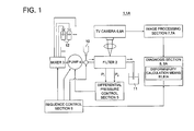
- Fig.1 shows a constitution diagram of a blood fluidity measurement apparatus 1 according to an embodiment of the present invention.
- the blood fluidity measurement apparatus 1 is an apparatus, which introduces blood injected from an inlet 10 into a discharge section 11 through a filter 2, and investigates blood fluidity using information obtained from the above process.
- the aforesaid apparatus is provided with a TV camera 6 as an imaging means which takes an image of blood flow in the filter 2, an image processing section 7 as a detection means of the state of blood flow to detect the state of blood flow from moving images taken by the above TV camera 6, and a diagnosis section 8 to diagnose the above state of blood flow.
- the blood fluidity measurement apparatus 1 not only introduces blood to the filter 2 as it is, but also is provided with a plurality of solution bottles 12 connected to a channel through a mixer 3 for the purpose of introducing blood to the filter 2 after mixing the blood with other solutions such as a physiological salt solution, and a physiological active substance.
- Blood and so on, which are introduced to the filter 2 are designed so that the desired amount ofblood and others are flowed, by controlling a pump 4 with a differential pressure controlling part 5 to regulate differential pressure in front of and behind the filter 2.
- the mixer 3, the pump 4, a valve of the inlet 10, and the diagnosis section 8 are integrated and controlled by a sequence control part 9.
- the blood fluidity measurement apparatus 1 and a fluidity measurement method which will be described later are not limited specifically, however it is preferable that they are employed in case of calculating a deformability of red blood cells which are hard to clog.
- the filter 2 is provided with apertures 23 composed of a group of fine channels between a silicon single crystal substrate 21 and a glass flat board 22, as shown in a cross section of Fig. 2 .
- a base board 24 and an external cylinder 25 are arranged in order to introduce blood into the above opening 23 and then discharge the blood.
- the base board 24 has an inlet port 26 and an outlet 27 ofblood, and the blood flows following arrows in the figure.
- Each pressure in front of and behind the opening 23 is detected by pressure sensors 28 and 29, and pressure signals P1 and P2 caused by the pressures are sent to the differential pressure control part 5 shown in Fig. 1 .
- the opening 23 the filter 2 comprises is, as shown in Figs. 3a and 3b , provided with a lot of gates 30 formed as a part sandwiched between two hexagonal banks 31.
- Fig. 3a is a top view of a part of the opening 23 when viewed from glass flat board 22, and Fig. 3b is a side view of opening 23 when viewed from a downstream side.
- the upper surface ofbank 31 is made flat, and is joined with the glass flat board 22, not shown in Figs. 3a and 3b .
- Constituents in blood introduced from the feed port 26, for example blood cells pass down through the gate 30 of Fig. 3a while being transformed.
- the above opening 23 is formed in the sizes shown in Figs. 3a and 3b , but is not particularly limited to them.
- the width of the gate 30 (6.4 ⁇ m in Fig. 3a ) is required to be smaller than the size of an object, in which transformation is observed, for example a blood cell size of a red blood cell (about 8
- the TV camera 6 is, for example, a digital CCD camera, and a high-speed camera having enough resolution to take moving images of blood flow.
- the above TV camera 6 is arranged at the upper part of the filter 2, and takes images, from a side of the glass flat board 22, of blood flow passing through the opening 23.
- the area of taking an image may, as shown in Fig. 3a , be an area including the internal area A, the inlet area B, and the outlet area C of a plurality of gates 30. However, the area of taking an image may includes any two of areas A through C of at least one gate 30 or may include every internal area A for the plurality of gates 30. It is designed that the moving images ofblood flow obtained by the TV camera 6 can be displayed on a not illustrated display.
- the above TV camera may be a camera for taking a still image.
- the image processing section 7 is provided with an analytical means such as a CPU or a memory means such as a semiconductor memory, and is electrically connected with the TV camera 6.
- the image processing section 7 processes moving images of blood flow obtained by the TV camera 6, and calculates a velocity of blood cells in blood at each area of areas A through C in the plurality og gates 30.
- the calculation in this case, in alt least one gate 30, may be performed for any two of areas A through C.
- the calculated blood velocity can be displayed on a not illustrated display.
- a diagnosis section 8 is provided with a deformability calculation means 81, which calculates a deformability ofblood cells by the velocity ofblood cells obtained by the image processing section 7, in addition to an analytical means such as a CPU or a memory means such as a semiconductor memory, and is electrically connected with the image processing section 7.
- the diagnosis section 8 calculates the deformability ofblood cells such as a ratio of velocities R and velocity difference D which are described later, as a fluidity of blood and diagnoses a degree of health ofblood by the deformability of blood. Further the diagnosis section 8 is provided with data which are necessary for judging the degree of health of blood.
- the calculated deformability and the diagnosis result can be displayed on a not illustrated display.
- the diagnosis section 8 may be constituted in an integrated fashion with the image processing section 7 using a PC or other means.
- blood for measurement is charged into the inlet 10, and at the same time, a physiological salt solution or others is added to a solution bottle 12, as needed. Then, blood and a physiological salt solution or others (hereinafter, referred to as blood) are flowed to the filter 2 by putting differential pressure on the filter 2, and at the same time, images ofblood flow passing through the gate 30 are taken by the TV camera 6.
- a physiological salt solution or others hereinafter, referred to as blood
- one of the gates 30 to be inspected is set (S1). Then the velocity ofblood cells at the set gate 30 is calculated by the image processing section 7(S2).
- a velocity V A at internal area A, a velocity V B at internal area B, a velocity V C at internal area C of gate 30 are calculated.
- the state of blood flow at the outlet area C of the gate 30 is measured (S3).
- the velocity to be calculated can be value represented by one blood cell each for each area or can be a mean value of calculated velocities of a plurality of blood cells.
- V A and V B For the calculation of velocity, as described above, the calculation of two velocities among velocities V A , V B , V C suffices. It is preferable to calculate V A and V B because it is difficult for the flow of V C to flow in the direction of the centerline of gate 30.
- a ratio of the speed ratio R and so on with the blood of a standard degree of health may be calculated.
- a ratio of the speed ratio R and so on with normal saline of which speeds at each of areas A through C of gate 30 should not change may be calculated.
- a conversion table of the deformability and speed ratio R obtained by a filtration method is kept as data, and deformability of the object blood may be calculated from the speed ration by using the table.
- the filtration is a known method which obtains the deformability from changes of pressure.
- the above described deformability can be arbitrarily calculated for the blood cells included in the image by the step of calculation. Therefore the deformability of bloods can be quantified in a short time, without requiring the operation of the deformability calculation for the individual blood cells as the conventional method.
- the processing is, for example, a processing which obtains a representative value for the deformability by calculating the average value for all gates, and is performed at the diagnosis section 8. In ca se when a plurality of types of deformability are calculated, the processing is performed each by each.
- the diagnosis section 8 diagnoses regarding to the deformability (S6).
- the speed ratio R and the speed difference D is compared with the speed ration R S and the speed difference D S of standard blood. If the speed ratio R is larger than the speed ration R S of the standard blood, the blood is superior in the deformability and it can be said that the blood has a higher degree of health than the standard blood. Further, if the speed difference D is larger than the speed difference D S of the standard blood, similarly, the blood is superior in the deformability and it can be said that the blood has a higher degree of health than the standard blood.
- the deformability which has been obtained as a ratio with the standard blood is diagnosed, for example, it can be regarded that it is superior when the speed ratio R/R S is larger than 1, and that it is inferior when the speed ratio R/R S is smaller than 1. Further, in case when the deformability which has been obtained as a ratio with the normal saline is diagnosed, for example, it can be regarded that it is superior when the speed ratio is nearer to 1, and that it is inferior when the speed ratio is nearer to 0.
- the above apparatus is provided with the TV camera 6 which takes an image of a flow of the blood at any two areas among areas A through C, the image processing section 7 which calculates the velocity ofblood cells in the blood by the image taken by the TV camera 6, and the deformability calculation means 81 which calculates the deformability ofblood cells as a fluidity of blood, therefore in case of a timing when an image is taken by the TV camera 6, deformability of all the blood included in the image can be calculated arbitrarily as blood fluidity from the velocity.
- the quantification operation is not needed to perform for each blood cell individually as the conventional method, the quantification of deformability ofblood cells can be performed in a shorter time.
- the blood fluidity measurement apparatus 1A is, as shown in Fig.1 , provided with a TV camera 6A in the above-described embodiment, an image processing section 7A, a diagnosis section 8A, and a modified deformability calculation means 81.
- the blood fluidity measurement apparatus 1A in the modified example of the embodiment and a fluidity measuring method using the blood fluidity measurement apparatus which will be described later is not particularly limited. However it is desirable to be used for calculating de deformability of white blood cells which are larger in diameter than red blood cells and is easy to clog at the gate 30.
- TV 6A when the area of taking picture of the TV 6A includes at least the internal area A of each of the plurality of gates 30. Other locations than this area of talking picture, too, are configured as same as TV 6 of above described embodiment
- the image processing section 7A is provided with an analytical means such as CPU and a memory means such as a semiconductor memory, and is electrically connected with the TV camera 6A.
- the image processing section 7A processes moving images of blood flow obtained by the TV camera 6A, and calculates a velocity of blood cells in blood at each area of areas A in the plurality of gates 30. The calculated blood velocity can be displayed on a not illustrated display.
- the image processing section 7A is further provided with data of a velocity of blood cells of the blood of the standard health at the internal area A.
- a diagnosis section 8A is provided with the deformability calculation means 81, which calculates the deformability of blood cells by the velocity of blood cells obtained by the image processing section 7A, in addition to the analytical means such as a CPU or the memory means such as a semiconductor memory, and is electrically connected with the image processing section 7A.
- the diagnosis section 8A calculates the deformability ofblood cells such as a gate number N which will be described later and gate number ratio L of velocities R, as a fluidity ofblood and diagnoses the degree of health ofblood by the deformability. Further the diagnosis section 8A is provided with data which are necessary for judging the degree of health ofblood.
- the diagnosis section 8A may be constituted in an integrated fashion with the image processing section 7A using a PC or other means.
- the blood fluidity measurement method via the blood fluidity measurement apparatus 1 A according to the modified embodiment will be described.
- steps until a step of taking an image of blood flow after blood is flowed in the filter 2 is same as the embodiment described above.
- One example of the image ofblood flow taken in the steps is shown in Fig. 6 .
- clogs of white blood cells happen at the gate 30 where the color of the area A is light.
- White blood is easy to clog at the gate 30 because the diameter of white blood cells is larger than the red blood cells.
- one of the gates 30 to be inspected is set (S1). Then the velocity ofblood cells at the set gate 30 is calculated by the image processing section 7A (S2).
- the velocity to be calculated can be a value represented by one blood cell for each area or can be a mean value of calculated velocities of a plurality of blood cells.
- the clog at gate 30 is detected by the image processing section 7A (S3). This is to detect a state like the state described above in which white blood cells clog at gate 30.
- the gate 30 becomes to be this state of clog, the blood flow is blocked and the velocity of the blood flow becomes extremely low. Therefore, the clog can be detected by comparing the velocity V A ofblood cells at the internal area A with a predetermined threshold value.
- the predetermined threshold value as a preferable value is a half of a velocity V S of blood cells in blood when blood having a standard fluidity flows in the internal area and is, more preferably 5% of the velocity V S of blood cells in blood when blood having a standard fluidity flows in the internal area.
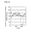
- Fig. 8 shows a change of the velocity ofblood cells at the internal area A when the standard blood is flown.
- the solid line and the broken line in the figure are respectively a velocity of different gates, and the horizontal line represents frame numbers of moving image of blood flow.
- the velocity ofblood cells shown by the solid line keeps approximately constant over all the frames, however the velocity ofblood cells shown by the broken line keeps goes down extremely temporarily.
- the temporal going down of the velocity of blood cells represents that white blood cells clog at a position where they advance with some extent in the internal area A. Therefore the ratio of the velocity of white blood cells (about 4 cm/ms) when they are clogged, to the velocity (about 70 cm/ms) at the part where blood cells flow healthily can be said threshold value to detect clog.
- steps up to here are performed for all gates 30.
- the deformability ofblood cells is calculated by the deformability calculation means 81 as a fluidity of blood (S5). Specifically, the gate number N where the clogs happen, and/or the gate number ratio L which is a ratio of the gate number N to the total number of all gates 30 are calculated, as the deformability.
- the deformability of white blood cells can be quantified in a short time, by detecting clogs at the gate 30 and calculating the gate number N and/or the gate number ratio L as the deformability. Further the quantification of the deformability can be achieved only by one or two drops ofblood.
- diagnosis section 8A performs the diagnosis for the deformability (S6).
- the diagnosis is performed by comparing the gate number N and/or the gate number ratio L obtained as the deformabilities with similar deformabilities of the blood of a standard degree of health. These deformabilities are diagnosed as higher degree of health then a standard, when they are smaller than the similar deformabilities of the blood of the standard degree of health.
- the deformability of white blood cells can be quantified in a short time only with a small quantity of blood, because the velocity V A of blood at the internal area of gate 30 is calculated, the gate number N where the velocity V A is lower than the predetermined threshold value and/or the gate number ratio L which is the ratio of the gate number N to the total number of all gates 30 a as the deformability are calculated by the image processing section 7A.
Landscapes
- Health & Medical Sciences (AREA)
- Engineering & Computer Science (AREA)
- Life Sciences & Earth Sciences (AREA)
- Physics & Mathematics (AREA)
- Chemical & Material Sciences (AREA)
- General Physics & Mathematics (AREA)
- Biomedical Technology (AREA)
- General Health & Medical Sciences (AREA)
- Immunology (AREA)
- Pathology (AREA)
- Biochemistry (AREA)
- Analytical Chemistry (AREA)
- Hematology (AREA)
- Food Science & Technology (AREA)
- Molecular Biology (AREA)
- Ecology (AREA)
- Medicinal Chemistry (AREA)
- Urology & Nephrology (AREA)
- Biophysics (AREA)
- Multimedia (AREA)
- Theoretical Computer Science (AREA)
- Computer Vision & Pattern Recognition (AREA)
- Signal Processing (AREA)
- Dispersion Chemistry (AREA)
- Fluid Mechanics (AREA)
- Investigating Or Analysing Biological Materials (AREA)
- Measuring Pulse, Heart Rate, Blood Pressure Or Blood Flow (AREA)
- Investigating Or Analysing Materials By Optical Means (AREA)
- Measurement Of The Respiration, Hearing Ability, Form, And Blood Characteristics Of Living Organisms (AREA)
Abstract
Description
- The present invention relates to a blood fluidity measurement apparatus and a blood fluidity measurement method.
- In recent years, along with increasing awareness of health, blood fluidity has been paid attention as a health barometer. The fluidity is also called as the degree of smoothness, and it means that the higher the fluidity or the smoothness is the better in health.
- As a method for investigating the above blood fluidity, it has been known that, as described for example in
Patent Document 1, blood is allowed to pass through a filter with fine grooves, and the time required for passing through the filter is measured. Further, it is also possible for the method ofPatent Document 1 to grasp visually the blood fluidity by observing with a camera blood cells passing through the filter using a filter substrate made of a transparent glass. Further, as described inNon Patent Document 1, a method for evaluating a deformability (ease of deformation) of blood cells which is a representative parameter ofblood fluidity, by an image capturing deforming blood in a filter has been proposed. - These methods are methods for investigating mainly fluidity of blood cells. For example, in
Patent Document 2, a method for capturing movements of white blood cells in an adherence phenomenon in which white blood cells adhere to blood veins which is particular to white blood cells. In this method, a moving velocity and so on ofblood cells in a process to adhere to blood veins can be calculated by digital processing the image capturing the movement of the white blood cell.
Patent Document 1: Japanese Patent No.2685544
Patent Document 2: Japanese Patent Application Publication No.2001-264318
Non Patent Document 1: Tsutomu Tajikawa et al. "Visualization and Observation of Deformation of Human Red Blood Cell Passing Through a Micro-channel Array as a Model of Human blood Capillary", pages 84-91, December 2005, Vol.25 No.12 Transaction of the Visualization Society of Japan. - However, with the method described in
Patent Document 1, it is not possible to make a quantitative evaluation for the blood fluidity, especially for deformability of blood. With the technology described inPatent Document 2 regarding to the movement of white blood cells, it is not possible to quantify the movement of white blood cells either. Further, with the technology ofNon Patent Document 1, the operation of the quantification is time consuming because the operation is performed each by each for each blood cell although the quantification of the deformability is tried. - The present invention has been achieved in consideration of the above problems, and it is an object of the invention to provide a blood fluidity measurement apparatus and a blood fluidity measurement method, which can evaluate the deformability ofblood cells which is a representative parameter of blood fluidity, in a short time.
- To solve the above-described problems, the invention described in
Claim 1 is characterized in that a blood fluidity measurement apparatus which measures a blood fluidity by flowing blood in a plurality of gates each of which is formed to be narrower than a blood diameter, comprises: - an imaging means which takes an image of blood flow in each of any two areas of an internal area, an inlet area and an outlet area of the gate, or in each internal area of the plurality of the gates;
- a velocity calculation means which calculates a velocity of blood cells in the blood by the image taken by the imaging means; and
- a deformability calculation means which calculates a deformability ofblood cells as a blood fluidity, by the velocity.
- The invention described in
Claim 2 is the blood fluidity measurement apparatus described inClaim 1, characterized in that: - the imaging means takes an image ofblood flow in any two areas of an internal area, an inlet area and an outlet area of the gate,
- the velocity calculation means calculates a velocity of blood cells of each of the two areas at least at one gate; and
- the deformability calculation means calculates a difference or a ration of velocities as a deformability of blood cells.
- The invention described in
Claim 3 is the blood fluidity measurement apparatus described inClaim 1, characterized in that: - the imaging means takes an image of blood flow in each internal area of the plurality of the gates;
- the velocity calculation means calculates a velocity of blood cells in each area;
- the deformability calculation means calculates a number of gates in which the velocity is less than or equal to a predetermined threshold value, as a deformability of blood.
- The invention described in
Claim 4 is the blood fluidity measurement apparatus described inClaim 1, characterized in that: - the imaging means takes an image ofblood flow in each internal area of the plurality of the gates;
- the velocity calculation means calculates a velocity of blood cells in each area;
- the deformability calculation means calculates a ratio of a number of gates in which the velocity is less than or equal to a predetermined threshold value, to a total number of the gates, as a deformability of blood.
- The invention described in
Claim 5 is the blood fluidity measurement apparatus described inClaim 3 orClaim 4, characterized in that: - the deformability calculation means employs the a half of a velocity ofblood cells in blood when blood having a standard fluidity flows in the internal area, as the predetermined threshold value.
- The invention described in Claim 6 is a blood fluidity measurement apparatus described in
Claim 3 orClaim 4, characterized in that - the deformability calculation means employs 5% of a velocity ofblood cells in blood when blood having a standard fluidity flows in the internal area, as the predetermined threshold value.
- The invention described in Claim 7 is a blood fluidity measurement method characterized in that the method comprises measuring a blood fluidity using the blood fluidity measurement apparatus described in any one of
Claim 1 through 6. - According to the invention described in
Claim 1, since there are provided an imaging means which takes an image of blood flow in each of any two areas of an internal area, an inlet area and an outlet area of the gate, or in each internal area of the plurality of the gates; a velocity calculation means which calculates a velocity ofblood cells in the blood by the image taken by the imaging means; and a deformability calculation means which calculates a deformability of blood cells as a blood fluidity, by the velocity, therefore, in case of a timing when an image is taken by the imaging means, deformability of all the blood included in the image can be calculated arbitrarily as blood fluidity from the velocity. As a result, compared to conventional cases in which the quantification operation is performed for each blood cell individually, the quantification of deformability ofblood cells can be performed in a shorter time. -
-
Fig.1 is a schematic constitution diagram of a blood fluidity measurement apparatus according to an embodiment of the present invention. -
Fig. 2 is a cross section of a filter according to an embodiment of the present invention. -
Fig. 3a is a partial top view of a gate according to an embodiment of the present invention, andFig. 3b is a side view when viewed from a downstream side of the gate. -
Fig. 4 is a flow chart of a step in which moving images of blood flow is image processed to investigate fluidity. -
Fig. 5 is a figure showing a blood cell flowing in each area of the gate. -
Fig. 6 is a figure showing an example of an image of blood flow, in which a gate is clogged. -
Fig. 7 is a flow chart of a step in which moving images of blood flow is processed to investigate fluidity. -
Fig. 8 is a figure showing a change of a velocity of blood cell in standard blood which flow in an internal area of the gate. -
- 1, 1A, and 1B:
- blood fluidity measurement apparatus
- 6, 6A, and 1B:
- TV camera (a means for taking an image)
- 7:
- Image processing section (a detection means for the state of blood flow)
- 30:
- Gate
- A:
- Internal area
- B:
- Inlet area
- C:
- Outlet area
- D:
- Speed difference
- L:
- Ratio of gate numbers
- N:
- Gate number
- R
- Velocity ratio
- VA:
- Velocity of blood cell at internal area
- Embodiments of the present invention will hereinafter be descried with reference to figures.
- First, regarding the blood fluidity measurement apparatus according to the present embodiment, an outline of a constitution thereof will be described
-
Fig.1 shows a constitution diagram of a bloodfluidity measurement apparatus 1 according to an embodiment of the present invention. The bloodfluidity measurement apparatus 1 is an apparatus, which introduces blood injected from aninlet 10 into adischarge section 11 through afilter 2, and investigates blood fluidity using information obtained from the above process. The aforesaid apparatus is provided with a TV camera 6 as an imaging means which takes an image of blood flow in thefilter 2, an image processing section 7 as a detection means of the state of blood flow to detect the state of blood flow from moving images taken by the above TV camera 6, and a diagnosis section 8 to diagnose the above state of blood flow. - Further, the blood
fluidity measurement apparatus 1 not only introduces blood to thefilter 2 as it is, but also is provided with a plurality ofsolution bottles 12 connected to a channel through amixer 3 for the purpose of introducing blood to thefilter 2 after mixing the blood with other solutions such as a physiological salt solution, and a physiological active substance. Blood and so on, which are introduced to thefilter 2, are designed so that the desired amount ofblood and others are flowed, by controlling apump 4 with a differentialpressure controlling part 5 to regulate differential pressure in front of and behind thefilter 2. Themixer 3, thepump 4, a valve of theinlet 10, and the diagnosis section 8 are integrated and controlled by asequence control part 9. - Further, the blood
fluidity measurement apparatus 1 and a fluidity measurement method which will be described later are not limited specifically, however it is preferable that they are employed in case of calculating a deformability of red blood cells which are hard to clog. - Next, major elements among the constituent elements of the above-described blood
fluidity measurement apparatus 1 will be detailed. - The
filter 2 is provided withapertures 23 composed of a group of fine channels between a siliconsingle crystal substrate 21 and a glassflat board 22, as shown in a cross section ofFig. 2 . In order to introduce blood into theabove opening 23 and then discharge the blood, abase board 24 and anexternal cylinder 25 are arranged. Thebase board 24 has aninlet port 26 and anoutlet 27 ofblood, and the blood flows following arrows in the figure. Each pressure in front of and behind theopening 23 is detected bypressure sensors pressure control part 5 shown inFig. 1 . - The
opening 23 thefilter 2 comprises is, as shown inFigs. 3a and 3b , provided with a lot ofgates 30 formed as a part sandwiched between twohexagonal banks 31.Fig. 3a is a top view of a part of theopening 23 when viewed from glassflat board 22, andFig. 3b is a side view ofopening 23 when viewed from a downstream side. Theupper surface ofbank 31 is made flat, and is joined with the glassflat board 22, not shown inFigs. 3a and 3b . Constituents in blood introduced from thefeed port 26, for example blood cells, pass down through thegate 30 ofFig. 3a while being transformed. Theabove opening 23 is formed in the sizes shown inFigs. 3a and 3b , but is not particularly limited to them. However, the width of the gate 30 (6.4 µ m inFig. 3a ) is required to be smaller than the size of an object, in which transformation is observed, for example a blood cell size of a red blood cell (about 8 µ m). - The TV camera 6 is, for example, a digital CCD camera, and a high-speed camera having enough resolution to take moving images of blood flow. The above TV camera 6 is arranged at the upper part of the
filter 2, and takes images, from a side of the glassflat board 22, of blood flow passing through theopening 23. The area of taking an image may, as shown inFig. 3a , be an area including the internal area A, the inlet area B, and the outlet area C of a plurality ofgates 30. However, the area of taking an image may includes any two of areas A through C of at least onegate 30 or may include every internal area A for the plurality ofgates 30. It is designed that the moving images ofblood flow obtained by the TV camera 6 can be displayed on a not illustrated display. The above TV camera may be a camera for taking a still image. - The image processing section 7 is provided with an analytical means such as a CPU or a memory means such as a semiconductor memory, and is electrically connected with the TV camera 6. The image processing section 7 processes moving images of blood flow obtained by the TV camera 6, and calculates a velocity of blood cells in blood at each area of areas A through C in the plurality og
gates 30. The calculation in this case, in alt least onegate 30, may be performed for any two of areas A through C. The calculated blood velocity can be displayed on a not illustrated display. - A diagnosis section 8 is provided with a deformability calculation means 81, which calculates a deformability ofblood cells by the velocity ofblood cells obtained by the image processing section 7, in addition to an analytical means such as a CPU or a memory means such as a semiconductor memory, and is electrically connected with the image processing section 7. The diagnosis section 8 calculates the deformability ofblood cells such as a ratio of velocities R and velocity difference D which are described later, as a fluidity of blood and diagnoses a degree of health ofblood by the deformability of blood. Further the diagnosis section 8 is provided with data which are necessary for judging the degree of health of blood. The calculated deformability and the diagnosis result can be displayed on a not illustrated display. The diagnosis section 8 may be constituted in an integrated fashion with the image processing section 7 using a PC or other means.
- Next, a blood fluidity measurement method via the blood
fluidity measurement apparatus 1 according to an embodiment of the present invention will be described. - First, steps until a step of taking an image of blood flow after blood is flowed in the
filter 2 will be described. - First, blood for measurement is charged into the
inlet 10, and at the same time, a physiological salt solution or others is added to asolution bottle 12, as needed. Then, blood and a physiological salt solution or others (hereinafter, referred to as blood) are flowed to thefilter 2 by putting differential pressure on thefilter 2, and at the same time, images ofblood flow passing through thegate 30 are taken by the TV camera 6. - Next, a process, in which images of moving images of blood flow are processed to investigate the fluidity, will be described. This process is executed following steps shown in
Fig. 4 . - First, one of the
gates 30 to be inspected is set (S1). Then the velocity ofblood cells at theset gate 30 is calculated by the image processing section 7(S2). - In calculating the velocity of blood cells, as shown in
Fig.5 , a velocity VA at internal area A, a velocity VB at internal area B, a velocity VC at internal area C ofgate 30 are calculated. At this occasion, it is preferable to calculate the velocity of bloods on the center line of thegate 30. After that, the state of blood flow at the outlet area C of thegate 30 is measured (S3). To calculating the above speeds, methods described in Japanese Patent Application Publications No.H2-257931 H6-18539 2001-264318 2006-223761 gate 30. - After the above calculation of blood cells (S2 of
Fig. 4 ), the deformability calculation means 81 calculates a deformability ofblood cells as a fluidity of blood (S3). Specifically, a speed ratio R and a speed difference D are calculated. At least one of R1 =VA/VB, R2 =VAVC, R3 =VC/VB as the speed ratio R, and D1 =VA-VB, D2 =VA-VC, D3 =VC/VB as the speed difference D are each calculated. Only either one of the speed ratio R and the speed ratio D may be calculated. - Further as the deformability of the blood cells, a ratio of the speed ratio R and so on with the blood of a standard degree of health may be calculated. In more details, a velocity VS, a speed ratio RS and a speed difference D1 of standard blood at the internal area A are stored in advance or kept as data, and each of ratios with the standard blood that is at least one of =VA/VS, R/RS, and D/Ds may be calculated, though it is necessary that the speed ratio or the speed difference are calculated for the velocities of the standard blood and the object blood at the same area, when the speed ratio or the speed difference are calculated.
- Further as the deformability of the blood cells, a ratio of the speed ratio R and so on with normal saline of which speeds at each of areas A through C of
gate 30 should not change may be calculated. In more details, a velocity Vo, a speed ratio RO and a speed difference DO of normal saline at the internal area A are stored in advance or kept as data, and each of ratios with the normal saline that is at least one of =VO/VA and RO/R may be calculated, though it is necessary that the speed ratio R and RO are calculated for the velocities of the normal saline and the object blood at the same area, when the ratio of the speed ratio is calculated. - Further a conversion table of the deformability and speed ratio R obtained by a filtration method is kept as data, and deformability of the object blood may be calculated from the speed ration by using the table. Here, the filtration is a known method which obtains the deformability from changes of pressure.
- At a timing when an image is taken by a TV camera 6, the above described deformability can be arbitrarily calculated for the blood cells included in the image by the step of calculation. Therefore the deformability of bloods can be quantified in a short time, without requiring the operation of the deformability calculation for the individual blood cells as the conventional method.
- After calculating the deformability, the steps till now (S1 through S3) are performed for all gates 30 (S4), subsequently, a static calculation processing is performed (S5). The processing is, for example, a processing which obtains a representative value for the deformability by calculating the average value for all gates, and is performed at the diagnosis section 8. In ca se when a plurality of types of deformability are calculated, the processing is performed each by each.
- Finally, the diagnosis section 8 diagnoses regarding to the deformability (S6). In the diagnosis, the speed ratio R and the speed difference D is compared with the speed ration RS and the speed difference DS of standard blood. If the speed ratio R is larger than the speed ration RS of the standard blood, the blood is superior in the deformability and it can be said that the blood has a higher degree of health than the standard blood. Further, if the speed difference D is larger than the speed difference DS of the standard blood, similarly, the blood is superior in the deformability and it can be said that the blood has a higher degree of health than the standard blood.
- Further, in case when the deformability which has been obtained as a ratio with the standard blood is diagnosed, for example, it can be regarded that it is superior when the speed ratio R/RS is larger than 1, and that it is inferior when the speed ratio R/RS is smaller than 1. Further, in case when the deformability which has been obtained as a ratio with the normal saline is diagnosed, for example, it can be regarded that it is superior when the speed ratio is nearer to 1, and that it is inferior when the speed ratio is nearer to 0.
- As described above, according to the blood
fluidity measurement apparatus 1 of the present embodiment, the above apparatus is provided with the TV camera 6 which takes an image of a flow of the blood at any two areas among areas A through C, the image processing section 7 which calculates the velocity ofblood cells in the blood by the image taken by the TV camera 6, and the deformability calculation means 81 which calculates the deformability ofblood cells as a fluidity of blood, therefore in case of a timing when an image is taken by the TV camera 6, deformability of all the blood included in the image can be calculated arbitrarily as blood fluidity from the velocity. As a result, the quantification operation is not needed to perform for each blood cell individually as the conventional method, the quantification of deformability ofblood cells can be performed in a shorter time. - Subsequently, an modified example of the blood
fluidity measurement apparatus 1 will be described. Any constituent element similar to the above embodiment will be denoted by the same reference numerals, and their descriptions will be omitted. - The blood fluidity measurement apparatus 1A is, as shown in
Fig.1 , provided with a TV camera 6A in the above-described embodiment, an image processing section 7A, a diagnosis section 8A, and a modified deformability calculation means 81. - The blood fluidity measurement apparatus 1A in the modified example of the embodiment and a fluidity measuring method using the blood fluidity measurement apparatus which will be described later is not particularly limited. However it is desirable to be used for calculating de deformability of white blood cells which are larger in diameter than red blood cells and is easy to clog at the
gate 30. - It is fine for TV 6A, when the area of taking picture of the TV 6A includes at least the internal area A of each of the plurality of
gates 30. Other locations than this area of talking picture, too, are configured as same as TV 6 of above described embodiment - The image processing section 7A is provided with an analytical means such as CPU and a memory means such as a semiconductor memory, and is electrically connected with the TV camera 6A. The image processing section 7A processes moving images of blood flow obtained by the TV camera 6A, and calculates a velocity of blood cells in blood at each area of areas A in the plurality of
gates 30. The calculated blood velocity can be displayed on a not illustrated display. The image processing section 7A is further provided with data of a velocity of blood cells of the blood of the standard health at the internal area A. - A diagnosis section 8A is provided with the deformability calculation means 81, which calculates the deformability of blood cells by the velocity of blood cells obtained by the image processing section 7A, in addition to the analytical means such as a CPU or the memory means such as a semiconductor memory, and is electrically connected with the image processing section 7A. The diagnosis section 8A calculates the deformability ofblood cells such as a gate number N which will be described later and gate number ratio L of velocities R, as a fluidity ofblood and diagnoses the degree of health ofblood by the deformability. Further the diagnosis section 8A is provided with data which are necessary for judging the degree of health ofblood. The diagnosis section 8A may be constituted in an integrated fashion with the image processing section 7A using a PC or other means.
- The blood fluidity measurement method via the blood fluidity measurement apparatus 1 A according to the modified embodiment will be described.
- First, steps until a step of taking an image of blood flow after blood is flowed in the
filter 2 is same as the embodiment described above. One example of the image ofblood flow taken in the steps is shown inFig. 6 . In the figure, clogs of white blood cells happen at thegate 30 where the color of the area A is light. White blood is easy to clog at thegate 30 because the diameter of white blood cells is larger than the red blood cells. - Next, a process in which the taken images of moving images of blood flow are processed to investigate the fluidity will be described. This process is executed following steps shown in
Fig. 7 . - First, one of the
gates 30 to be inspected is set (S1). Then the velocity ofblood cells at theset gate 30 is calculated by the image processing section 7A (S2). - In calculating the velocity ofblood cells, at least the velocity VA at internal area A of
gate 30 is calculated. At this occasion, it is preferable to calculate the velocity of bloods on the center line of thegate 30. For the calculating the velocity, same method as the embodiment described above can be used. The velocity to be calculated can be a value represented by one blood cell for each area or can be a mean value of calculated velocities of a plurality of blood cells. - Following to the calculation of the velocity of blood cells, the clog at
gate 30 is detected by the image processing section 7A (S3). This is to detect a state like the state described above in which white blood cells clog atgate 30. When thegate 30 becomes to be this state of clog, the blood flow is blocked and the velocity of the blood flow becomes extremely low. Therefore, the clog can be detected by comparing the velocity VA ofblood cells at the internal area A with a predetermined threshold value. The predetermined threshold value as a preferable value is a half of a velocity VS of blood cells in blood when blood having a standard fluidity flows in the internal area and is, more preferably 5% of the velocity VS of blood cells in blood when blood having a standard fluidity flows in the internal area. - Further the above described predetermined threshold value of 5% of the velocity VS depends on the data of the blood velocity which
Fig. 8 shows.Fig. 8 shows a change of the velocity ofblood cells at the internal area A when the standard blood is flown. The solid line and the broken line in the figure are respectively a velocity of different gates, and the horizontal line represents frame numbers of moving image of blood flow. According to the figure, the velocity ofblood cells shown by the solid line keeps approximately constant over all the frames, however the velocity ofblood cells shown by the broken line keeps goes down extremely temporarily. The temporal going down of the velocity of blood cells represents that white blood cells clog at a position where they advance with some extent in the internal area A. Therefore the ratio of the velocity of white blood cells (about 4 cm/ms) when they are clogged, to the velocity (about 70 cm/ms) at the part where blood cells flow healthily can be said threshold value to detect clog. - After completing the detection of clog, steps up to here (S1 through S3) are performed for all
gates 30. - Next, the deformability ofblood cells is calculated by the deformability calculation means 81 as a fluidity of blood (S5). Specifically, the gate number N where the clogs happen, and/or the gate number ratio L which is a ratio of the gate number N to the total number of all
gates 30 are calculated, as the deformability. - As explained above, according to the blood fluidity measurement apparatus 1A, mainly the deformability of white blood cells can be quantified in a short time, by detecting clogs at the
gate 30 and calculating the gate number N and/or the gate number ratio L as the deformability. Further the quantification of the deformability can be achieved only by one or two drops ofblood. - Finally, diagnosis section 8A performs the diagnosis for the deformability (S6). The diagnosis is performed by comparing the gate number N and/or the gate number ratio L obtained as the deformabilities with similar deformabilities of the blood of a standard degree of health. These deformabilities are diagnosed as higher degree of health then a standard, when they are smaller than the similar deformabilities of the blood of the standard degree of health.
- As explained above, according to the blood fluidity measurement apparatus 1A, mainly the deformability of white blood cells can be quantified in a short time only with a small quantity of blood, because the velocity VA of blood at the internal area of
gate 30 is calculated, the gate number N where the velocity VA is lower than the predetermined threshold value and/or the gate number ratio L which is the ratio of the gate number N to the total number of all gates 30 a as the deformability are calculated by the image processing section 7A. - Further, the present invention is not limited to the above-described embodiments and the modified examples thereof, and naturally it can appropriately be modified.
Claims (7)
- A blood fluidity measurement apparatus which measures blood fluidity by flowing blood in a plurality of gates, wherein a width of each of the plurality of gates is formed to be narrower than a diameter of blood cell, the blood fluidity measurement apparatus comprising:an imaging means which takes an image of blood flow at any two areas of an internal area, an inlet area and an outlet area of the gate, or at each internal area of the plurality of the gates;a velocity calculation means which calculates a velocity ofblood cells in blood by the image taken by the imaging means; anda deformability calculation means which calculates a deformability of blood cells as a blood fluidity, by the velocity.
- The blood fluidity measurement apparatus described in Claim 1, characterized in that:the imaging means takes an image of blood flow in any two areas of an internal area, an inlet area and an outlet area of the gates,the velocity calculation means calculates velocities of blood cells at the two areas of at least one of the gates; andthe deformability calculation means calculates a difference or a ration between each other of the velocities as the deformability ofblood cells.
- The blood fluidity measurement apparatus describe in Claim 1, characterized in that:the imaging means takes an image of blood flow at an internal area of each of the plurality of the gates;the velocity calculation means calculates a velocity of blood cells at the internal area;the deformability calculation means calculates a number of gates whose velocities are less than or equal to a predetermined threshold value, as the deformability ofblood.
- The blood fluidity measurement apparatus described in Claim 1, characterized in that:the imaging means takes an image ofblood flow at an internal area of each of the plurality of the gates;the velocity calculation means calculates a velocity of blood cells in the internal area;the deformability calculation means calculates a ratio of a number of gates whose velocities are less than or equal to a predetermined threshold value, to a total number of the gates, as the deformability ofblood.
- The blood fluidity measurement apparatus described in Claim 3 or Claim 4, characterized in that:the deformability calculation means employs a half of a velocity of blood cells in blood when blood having a standard fluidity flows in the internal area, as the predetermined threshold value.
- The blood fluidity measurement apparatus described in Claim 3 or Claim 4, characterized in that:the deformability calculation means employs a value which is 5% of a velocity ofblood cells in blood when blood having a standard fluidity flows in the internal area, as the predetermined threshold value.
- A blood fluidity measurement method characterized in that the method comprises measuring the blood fluidity using the blood fluidity measurement apparatus described in any one of Claims 1 to 6.
Applications Claiming Priority (2)
| Application Number | Priority Date | Filing Date | Title |
|---|---|---|---|
| JP2007306975 | 2007-11-28 | ||
| PCT/JP2008/069529 WO2009069418A1 (en) | 2007-11-28 | 2008-10-28 | Blood fluidity measurement apparatus and blood fluidity measurement method |
Publications (2)
| Publication Number | Publication Date |
|---|---|
| EP2216639A1 true EP2216639A1 (en) | 2010-08-11 |
| EP2216639A4 EP2216639A4 (en) | 2014-01-15 |
Family
ID=40678321
Family Applications (1)
| Application Number | Title | Priority Date | Filing Date |
|---|---|---|---|
| EP08853229.6A Withdrawn EP2216639A4 (en) | 2007-11-28 | 2008-10-28 | Blood fluidity measurement apparatus and blood fluidity measurement method |
Country Status (5)
| Country | Link |
|---|---|
| US (2) | US20100249621A1 (en) |
| EP (1) | EP2216639A4 (en) |
| JP (1) | JP5146463B2 (en) |
| CN (1) | CN101874201B (en) |
| WO (1) | WO2009069418A1 (en) |
Families Citing this family (22)
| Publication number | Priority date | Publication date | Assignee | Title |
|---|---|---|---|---|
| WO2010137470A1 (en) * | 2009-05-29 | 2010-12-02 | コニカミノルタオプト株式会社 | Device for measuring deformability and method for measuring deformability |
| CN101577845B (en) | 2009-06-01 | 2012-11-14 | 中兴通讯股份有限公司 | Method and device for processing switching control command |
| WO2012040067A2 (en) * | 2010-09-22 | 2012-03-29 | The Regents Of The University Of California | Method and device for high throughput cell deformability measurements |
| PT2768942T (en) * | 2011-10-17 | 2020-01-21 | Massachusetts Inst Technology | Intracellular delivery |
| CN102743165B (en) * | 2012-07-31 | 2013-11-20 | 刘常春 | Blood in vivo liquidity measuring device based on photoelectric volume pulse wave |
| EP2912434B1 (en) | 2012-10-24 | 2019-12-04 | The Regents of The University of California | System and method for deforming and analyzing particles |
| KR102243597B1 (en) | 2013-08-16 | 2021-04-26 | 메사추세츠 인스티튜트 오브 테크놀로지 | Selective delivery of material to cells |
| KR20170074235A (en) | 2014-10-31 | 2017-06-29 | 메사추세츠 인스티튜트 오브 테크놀로지 | Delivery of biomolecules to immune cells |
| CN107002089B (en) | 2014-11-14 | 2021-09-07 | 麻省理工学院 | Destruction and Field-Achieved Delivery of Compounds and Compositions into Cells |
| CN107250373A (en) | 2015-01-12 | 2017-10-13 | 麻省理工学院 | Gene editing via microfluidic delivery |
| AU2016289530B2 (en) | 2015-07-09 | 2021-05-06 | Massachusetts Institute Of Technology | Delivery of materials to anucleate cells |
| EP3344575B1 (en) | 2015-09-04 | 2020-04-15 | SQZ Biotechnologies Company | Intracellular delivery of biomolecules to cells comprising a cell wall |
| US10252260B2 (en) | 2016-04-01 | 2019-04-09 | CytoVale Inc. | System and method for deforming particles |
| CA3023092A1 (en) | 2016-05-03 | 2017-11-09 | Sqz Biotechnologies Company | Intracellular delivery of biomolecules to induce tolerance |
| AU2019234549B2 (en) | 2018-03-12 | 2026-02-12 | Sqz Biotechnologies Company | Methods for treating HPV-associated diseases |
| CA3131701A1 (en) | 2019-02-28 | 2020-09-03 | Sqz Biotechnologies Company | Delivery of biomolecules to pbmcs to modify an immune response |
| KR20210149791A (en) | 2019-04-08 | 2021-12-09 | 에스큐지 바이오테크놀로지스 컴퍼니 | Cartridge for use in a system for delivering a payload into a cell |
| CA3148774C (en) | 2019-07-31 | 2024-10-15 | CytoVale Inc. | SYSTEM AND METHOD FOR DETERMINING IMMUNE ACTIVITY |
| US11548003B1 (en) | 2022-01-13 | 2023-01-10 | CytoVale Inc. | System and method for determining an immune activation state |
| US11592371B1 (en) | 2022-01-13 | 2023-02-28 | CytoVale Inc. | System and method for determining an immune activation state |
| US11964281B2 (en) | 2022-02-03 | 2024-04-23 | CytoVale Inc. | System and method for correcting patient index |
| CN115146514B (en) * | 2022-07-31 | 2024-06-25 | 东南大学 | A method for simulating and predicting the rheological behavior of blood cells in blood flow |
Family Cites Families (13)
| Publication number | Priority date | Publication date | Assignee | Title |
|---|---|---|---|---|
| JP2685544B2 (en) * | 1988-11-11 | 1997-12-03 | 株式会社日立製作所 | Blood filter, blood test method, and blood test apparatus |
| JPH02257931A (en) | 1988-12-24 | 1990-10-18 | Hamamatsu Photonics Kk | Procedure and device for measuring blood flow rate in blood vessel |
| JPH02262057A (en) * | 1989-03-31 | 1990-10-24 | Aloka Co Ltd | Apparatus for measuring erythrocyte deformation |
| US5327777A (en) * | 1990-02-24 | 1994-07-12 | University Of Hertfordshire | Biorheological measurement |
| US5257529A (en) * | 1990-12-28 | 1993-11-02 | Nissho Corporation | Method and device for measurement of viscosity of liquids |
| CN2081535U (en) * | 1990-12-28 | 1991-07-24 | 天津中医学院 | Infrared multi-shearing viscosity-determining instrument |
| WO1992015878A1 (en) * | 1991-03-04 | 1992-09-17 | Kensey Nash Corporation | Apparatus and method for determining deformability of red blood cells of a living being |
| JPH0618539A (en) | 1992-07-02 | 1994-01-25 | Mitsubishi Kasei Corp | Method and apparatus for detecting speed of moving object |
| CN1192351A (en) * | 1998-03-26 | 1998-09-09 | 王明时 | Instrument for quick measuring blood viscosity |
| JP2001264318A (en) | 2000-03-15 | 2001-09-26 | Japan Science & Technology Corp | Analysis apparatus and analysis method for leukocyte adhesion phenomenon |
| US7542131B2 (en) * | 2003-06-23 | 2009-06-02 | Sewon Meditech, Inc. | Apparatus for measuring blood cell deformability |
| JP2005106778A (en) * | 2003-10-02 | 2005-04-21 | Fuji Photo Film Co Ltd | Filter chip, method for observing flow characteristics of cells and particles using the cells |
| JP4068099B2 (en) | 2005-02-21 | 2008-03-26 | 稔 冨田 | Biological component velocity measuring device and program thereof |
-
2008
- 2008-10-28 CN CN2008801176831A patent/CN101874201B/en not_active Expired - Fee Related
- 2008-10-28 US US12/744,604 patent/US20100249621A1/en not_active Abandoned
- 2008-10-28 WO PCT/JP2008/069529 patent/WO2009069418A1/en not_active Ceased
- 2008-10-28 JP JP2009543726A patent/JP5146463B2/en not_active Expired - Fee Related
- 2008-10-28 EP EP08853229.6A patent/EP2216639A4/en not_active Withdrawn
-
2014
- 2014-12-12 US US14/568,972 patent/US20150098626A1/en not_active Abandoned
Also Published As
| Publication number | Publication date |
|---|---|
| CN101874201A (en) | 2010-10-27 |
| JPWO2009069418A1 (en) | 2011-04-07 |
| WO2009069418A1 (en) | 2009-06-04 |
| CN101874201B (en) | 2012-08-15 |
| EP2216639A4 (en) | 2014-01-15 |
| US20150098626A1 (en) | 2015-04-09 |
| JP5146463B2 (en) | 2013-02-20 |
| US20100249621A1 (en) | 2010-09-30 |
Similar Documents
| Publication | Publication Date | Title |
|---|---|---|
| EP2216639A1 (en) | Blood fluidity measurement apparatus and blood fluidity measurement method | |
| US20100260391A1 (en) | Blood fluidity measurement system and blood fluidity measurement method | |
| JP5541280B2 (en) | Deformability measuring device and deformability measuring method | |
| CN102187217B (en) | Device for measuring blood cell deformability | |
| JP5387689B2 (en) | Blood cell trajectory display device | |
| JP5423671B2 (en) | Blood aggregating capacity measuring device | |
| CN102317775B (en) | Blood test apparatus | |
| US11137335B2 (en) | Method for evaluating fluid flow characteristics of lens-free CMOS optical array sensor package module having flow channel | |
| JP5655779B2 (en) | Aggregation amount measuring apparatus and aggregation amount measuring method | |
| JP2009276271A (en) | Blood fluidity measurement device | |
| JP2012247205A (en) | Blood examination apparatus | |
| WO2011010570A1 (en) | Apparatus for measuring amount of aggregates, and method for measuring amount of aggregates | |
| JP5182373B2 (en) | Microchip, blood characteristic analysis system, and blood characteristic analysis method | |
| WO2011065176A1 (en) | Microchip and blood analysis system | |
| JP2014041011A (en) | Blood agglutination analysis device | |
| WO2011065195A1 (en) | Microchip and film |
Legal Events
| Date | Code | Title | Description |
|---|---|---|---|
| PUAI | Public reference made under article 153(3) epc to a published international application that has entered the european phase |
Free format text: ORIGINAL CODE: 0009012 |
|
| 17P | Request for examination filed |
Effective date: 20100526 |
|
| AK | Designated contracting states |
Kind code of ref document: A1 Designated state(s): AT BE BG CH CY CZ DE DK EE ES FI FR GB GR HR HU IE IS IT LI LT LU LV MC MT NL NO PL PT RO SE SI SK TR |
|
| AX | Request for extension of the european patent |
Extension state: AL BA MK RS |
|
| DAX | Request for extension of the european patent (deleted) | ||
| RIC1 | Information provided on ipc code assigned before grant |
Ipc: G01N 33/49 20060101ALI20131205BHEP Ipc: G01N 11/04 20060101AFI20131205BHEP |
|
| A4 | Supplementary search report drawn up and despatched |
Effective date: 20131213 |
|
| STAA | Information on the status of an ep patent application or granted ep patent |
Free format text: STATUS: THE APPLICATION HAS BEEN WITHDRAWN |
|
| 18W | Application withdrawn |
Effective date: 20141219 |