EP2215821B1 - Method and apparatus for alert control - Google Patents
Method and apparatus for alert control Download PDFInfo
- Publication number
- EP2215821B1 EP2215821B1 EP08854999.3A EP08854999A EP2215821B1 EP 2215821 B1 EP2215821 B1 EP 2215821B1 EP 08854999 A EP08854999 A EP 08854999A EP 2215821 B1 EP2215821 B1 EP 2215821B1
- Authority
- EP
- European Patent Office
- Prior art keywords
- alert
- environmental
- event
- unfavorableness
- threshold
- Prior art date
- Legal status (The legal status is an assumption and is not a legal conclusion. Google has not performed a legal analysis and makes no representation as to the accuracy of the status listed.)
- Active
Links
- 238000000034 method Methods 0.000 title claims description 42
- 230000007613 environmental effect Effects 0.000 claims description 136
- 230000002349 favourable effect Effects 0.000 claims description 17
- 230000033001 locomotion Effects 0.000 claims description 15
- 230000015654 memory Effects 0.000 claims description 11
- 230000004044 response Effects 0.000 claims description 6
- 230000000694 effects Effects 0.000 claims description 5
- 230000000007 visual effect Effects 0.000 claims description 5
- 238000004590 computer program Methods 0.000 claims description 4
- 230000005236 sound signal Effects 0.000 claims description 3
- 238000012544 monitoring process Methods 0.000 description 29
- 238000010586 diagram Methods 0.000 description 16
- 238000012545 processing Methods 0.000 description 14
- 230000006854 communication Effects 0.000 description 13
- 238000004891 communication Methods 0.000 description 12
- 230000008901 benefit Effects 0.000 description 7
- 238000010295 mobile communication Methods 0.000 description 7
- 230000006870 function Effects 0.000 description 6
- 230000008447 perception Effects 0.000 description 4
- 238000005070 sampling Methods 0.000 description 4
- 230000005540 biological transmission Effects 0.000 description 2
- 230000009471 action Effects 0.000 description 1
- 230000006399 behavior Effects 0.000 description 1
- 230000001413 cellular effect Effects 0.000 description 1
- 230000008859 change Effects 0.000 description 1
- 230000007423 decrease Effects 0.000 description 1
- 238000011156 evaluation Methods 0.000 description 1
- 238000010438 heat treatment Methods 0.000 description 1
- 230000000977 initiatory effect Effects 0.000 description 1
- 238000012986 modification Methods 0.000 description 1
- 230000004048 modification Effects 0.000 description 1
- 230000003287 optical effect Effects 0.000 description 1
- 230000011664 signaling Effects 0.000 description 1
- 238000012546 transfer Methods 0.000 description 1
Images


Classifications
-
- H—ELECTRICITY
- H04—ELECTRIC COMMUNICATION TECHNIQUE
- H04M—TELEPHONIC COMMUNICATION
- H04M1/00—Substation equipment, e.g. for use by subscribers
- H04M1/72—Mobile telephones; Cordless telephones, i.e. devices for establishing wireless links to base stations without route selection
- H04M1/724—User interfaces specially adapted for cordless or mobile telephones
- H04M1/72448—User interfaces specially adapted for cordless or mobile telephones with means for adapting the functionality of the device according to specific conditions
- H04M1/72454—User interfaces specially adapted for cordless or mobile telephones with means for adapting the functionality of the device according to specific conditions according to context-related or environment-related conditions
-
- H—ELECTRICITY
- H04—ELECTRIC COMMUNICATION TECHNIQUE
- H04M—TELEPHONIC COMMUNICATION
- H04M1/00—Substation equipment, e.g. for use by subscribers
- H04M1/72—Mobile telephones; Cordless telephones, i.e. devices for establishing wireless links to base stations without route selection
- H04M1/724—User interfaces specially adapted for cordless or mobile telephones
- H04M1/72484—User interfaces specially adapted for cordless or mobile telephones wherein functions are triggered by incoming communication events
-
- H—ELECTRICITY
- H04—ELECTRIC COMMUNICATION TECHNIQUE
- H04M—TELEPHONIC COMMUNICATION
- H04M19/00—Current supply arrangements for telephone systems
- H04M19/02—Current supply arrangements for telephone systems providing ringing current or supervisory tones, e.g. dialling tone or busy tone
- H04M19/04—Current supply arrangements for telephone systems providing ringing current or supervisory tones, e.g. dialling tone or busy tone the ringing-current being generated at the substations
- H04M19/042—Current supply arrangements for telephone systems providing ringing current or supervisory tones, e.g. dialling tone or busy tone the ringing-current being generated at the substations with variable loudness of the ringing tone, e.g. variable envelope or amplitude of ring signal
- H04M19/044—Current supply arrangements for telephone systems providing ringing current or supervisory tones, e.g. dialling tone or busy tone the ringing-current being generated at the substations with variable loudness of the ringing tone, e.g. variable envelope or amplitude of ring signal according to the level of ambient noise
-
- H—ELECTRICITY
- H04—ELECTRIC COMMUNICATION TECHNIQUE
- H04M—TELEPHONIC COMMUNICATION
- H04M1/00—Substation equipment, e.g. for use by subscribers
- H04M1/72—Mobile telephones; Cordless telephones, i.e. devices for establishing wireless links to base stations without route selection
- H04M1/724—User interfaces specially adapted for cordless or mobile telephones
- H04M1/72448—User interfaces specially adapted for cordless or mobile telephones with means for adapting the functionality of the device according to specific conditions
- H04M1/72451—User interfaces specially adapted for cordless or mobile telephones with means for adapting the functionality of the device according to specific conditions according to schedules, e.g. using calendar applications
-
- H—ELECTRICITY
- H04—ELECTRIC COMMUNICATION TECHNIQUE
- H04M—TELEPHONIC COMMUNICATION
- H04M1/00—Substation equipment, e.g. for use by subscribers
- H04M1/72—Mobile telephones; Cordless telephones, i.e. devices for establishing wireless links to base stations without route selection
- H04M1/724—User interfaces specially adapted for cordless or mobile telephones
- H04M1/72448—User interfaces specially adapted for cordless or mobile telephones with means for adapting the functionality of the device according to specific conditions
- H04M1/72457—User interfaces specially adapted for cordless or mobile telephones with means for adapting the functionality of the device according to specific conditions according to geographic location
-
- H—ELECTRICITY
- H04—ELECTRIC COMMUNICATION TECHNIQUE
- H04M—TELEPHONIC COMMUNICATION
- H04M2250/00—Details of telephonic subscriber devices
- H04M2250/12—Details of telephonic subscriber devices including a sensor for measuring a physical value, e.g. temperature or motion
Definitions
- This application relates generally to a method and apparatus for alert control.
- US 2004/0127198 discloses techniques to automatically change the notification mode used by a mobile communications device to alert a user of an incoming communication to the mobile communications device.
- the notification mode is changed in response to a detected environmental condition.
- the mobile communications device monitors one or more environmental conditions, such as motion, light, sound, and heat, and compares the detected level of each environmental condition to a predetermined threshold. In response to the comparison result, the mobile communications device automatically adjusts the notification mode used to alert a user to an incoming communication.
- an apparatus as in claim 20 is disclosed.
- FIGURES 1 through 8B of the drawings like numerals being used for like and corresponding parts of the various drawings.
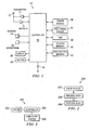
- FIGURE 1 is a block diagram of an electronic device, for example, mobile terminal 10, according to an exemplary embodiment of the present invention. It should be understood, however, that a mobile terminal as illustrated and hereinafter described is merely illustrative of an electronic device that would benefit from embodiments of the present invention and, therefore, should not be taken to limit the scope of the present invention. While one embodiment of the mobile terminal 10 is illustrated and will be hereinafter described for purposes of example, other types of electronic devices, such as, but not limited to, portable digital assistants (PDAs), pagers, mobile computers, desktop computers, televisions, gaming devices, laptop computers, cameras, video recorders, GPS devices and other types of electronic systems, may readily employ embodiments of the present invention. Furthermore, devices may readily employ embodiments of the present invention regardless of their intent to provide mobility.
- PDAs portable digital assistants
- Embodiments of the present invention will be primarily described below in conjunction with mobile communications applications. However, it should be understood that embodiments of the present invention may be utilized in conjunction with a variety of other applications, both in the mobile communications industries and outside of the mobile communications industries.
- the mobile terminal 10 comprises an antenna 12 (or multiple antennae) in operable communication with a transmitter 14 and a receiver 16.
- the mobile terminal 10 further comprises a controller 20 or other processing element that provides signals to and receives signals from the transmitter 14 and receiver 16, respectively.
- the signals comprise signaling information in accordance with the air interface standard of the applicable cellular system, and also user speech, received data and/or user generated data.
- the mobile terminal 10 may operate with one or more air interface standards, communication protocols, modulation types, and access types.
- the mobile terminal 10 may operate in accordance with any of a number of first, second, third and/or fourth-generation communication protocols or the like.
- the mobile terminal 10 may operate in accordance with second-generation (2G) wireless communication protocols IS-136 (TDMA), GSM, and IS-95 (CDMA), or with third-generation (3G) wireless communication protocols, such as UMTS, CDMA2000, WCDMA and TD-SCDMA, with fourth-generation (4G) wireless communication protocols, and/or the like.
- 2G second-generation
- 3G third-generation
- UMTS Universal Mobile Telecommunications
- CDMA2000 Code Division Multiple Access 2000
- WCDMA Wideband Code Division Multiple Access
- TD-SCDMA fourth-generation
- the controller 20 comprises circuitry desirable for implementing audio and logic functions of the mobile terminal 10.
- the controller 20 may comprise a digital signal processor device, a microprocessor device, various analog to digital converters, digital to analog converters, and for other support circuits. Control and signal processing functions of the mobile terminal 10 are allocated between these devices according to their respective capabilities.
- the controller 20 thus may also comprise the functionality to convolutionally encode and interleave message and data prior to modulation and transmission.
- the controller 20 may additionally comprise an internal voice coder, and may comprise an internal data modem.
- the controller 20 may comprise functionality to operate one or more software programs, which may be stored in memory.
- the controller 20 may operate a connectivity program, such as a conventional Web browser. The connectivity program may then allow the mobile terminal 10 to transmit and receive Web content, such as location-based content and/or other web page content, according to a Wireless Application Protocol (WAP), Hypertext Transfer Protocol (HTTP), and/or the like, for example.
- WAP Wireless Application Protocol
- HTTP Hypertext Transfer Protocol
- the mobile terminal 10 may also comprise a user interface including an output device such as a ringer, a conventional earphone and/or speaker 24, a microphone 26, a display 28, and/or a user input interface, which are coupled to the controller 20.
- the user input interface which allows the mobile terminal 10 to receive data, may comprise any of a number of devices allowing the mobile terminal 10 to receive data, such as a keypad 30, a touch display (not shown) or other input device.
- the keypad 30 may comprise the conventional numeric (0-9) and related keys (#, *), and other keys used for operating the mobile terminal 10.
- the keypad 30 may comprise a conventional QWERTY keypad arrangement.
- the keypad 30 may also comprise various soft keys with associated functions.
- the mobile terminal 10 may comprise an interface device such as a joystick or other user input interface.
- the mobile terminal 10 further comprises a battery 34, such as a vibrating battery pack, for powering various circuits that are required to operate the mobile terminal 10, as well as optionally providing mechanical vibration as a detectable output.
- the mobile terminal 10 comprises a media capturing element, such as a camera, video and/or audio module, in communication with the controller 20.
- the media capturing element may be any means for capturing an image, video and/or audio for storage, display or transmission.
- the camera module 36 may comprise a digital camera which may form a digital image file from a captured image.
- the camera module 36 comprises hardware, such as a lens or other optical component(s), and/or software necessary for creating a digital image file from a captured image.
- the camera module 36 may comprise only the hardware for viewing an image, while a memory device of the mobile terminal 10 stores instructions for execution by the controller 20 in the form of software for creating a digital image file from a captured image.
- the camera module 36 may further comprise a processing element such as a co-processor which assists the controller 20 in processing image data and an encoder and/or decoder for compressing and/or decompressing image data.
- the encoder and/or decoder may encode and/or decode according to a standard format, for example, a JPEG standard format.
- the mobile terminal 10 may further comprise a user identity module (UIM) 38.
- the UIM 38 may be a memory device having a built in processor.
- the UIM 38 may comprise, for example, a subscriber identity module (SIM), a universal integrated circuit card (UICC), a universal subscriber identity module (USIM), a removable user identity module (R-UIM), and/or the like.
- SIM subscriber identity module
- UICC universal integrated circuit card
- USIM universal subscriber identity module
- R-UIM removable user identity module
- the UIM 38 may store information elements related to a mobile subscriber.
- the mobile terminal 10 may be equipped with memory.
- the mobile terminal 10 may comprise volatile memory 40, such as volatile Random Access Memory (RAM) including a cache area for the temporary storage of data.
- RAM volatile Random Access Memory
- the mobile terminal 10 may also comprise other memory, for example, non-volatile memory 42, which may be embedded and/or may be removable.
- the non-volatile memory 42 may additionally or alternatively comprise an EEPROM, flash memory or the like, such as that available from the SanDisk Corporation of Sunnyvale, California, or Lexar Media Inc. of Fremont, California.
- the memories may store any of a number of pieces of information, and data, used by the mobile terminal 10 to implement the functions of the mobile terminal 10.
- the memories may comprise an identifier, such as an international mobile equipment identification (IMEI) code, which may uniquely identify the mobile terminal 10.
- IMEI international mobile equipment identification
- FIGURE 1 illustrates an example of a mobile terminal which may utilize embodiments of the present invention
- the mobile terminal 10 of FIGURE 1 is merely an exemplary device that may utilize embodiments of the present invention.
- any device having a processing element for managing timer operations may utilize embodiments of the present invention.
- such a device may also comprise or otherwise be in communication with a memory device and may also comprise some form of user interface.
- such devices could be, but are not limited to, portable digital assistants (PDAs), pagers, mobile computers, desktop computers, televisions, gaming devices, laptop computers, cameras, video recorders, GPS devices and other types of electronic systems.
- PDAs portable digital assistants
- a processing element such as those described above may be embodied in many ways.
- the processing element may be embodied as a processor, a coprocessor, a controller or various other processing means or devices including integrated circuits such as, for example, an ASIC (application specific integrated circuit), FPGA (field programmable gate array), and/or the like.
- ASIC application specific integrated circuit
- FPGA field programmable gate array
- Such events may comprise for example, receiving a phone call, receiving a message, receiving a voice mail notification, receiving an email, a calendar alarm, an alarm clock notification, and/or the like.
- FIGURE 2 is a flow chart of a method 200 for event alert according to an exemplary embodiment of the present invention. It should be understood, however, that the event alert method of FIGURE 2 as illustrated and hereinafter described is merely illustrative of an event alert method which may be employed to inform a user of an event, and therefore, should not be taken to limit the scope of the present invention.
- an event occurs.
- the event occurs in an electronic device, for example mobile terminal 10.
- the event may comprise: receiving a phone call, receiving a message, receiving a voice mail notification, receiving an email, generating a calendar alarm, generating an alarm clock notification, and/or the like.
- an event may be generated in the device, such as, a calendar event, an alarm clock event, and/or the like.
- the device may have an event communicated to it, such as, receiving a phone call, receiving a message, receiving a voice mail notification, receiving an email, and/or the like.
- processing the event may comprise performing one or more operations, for example, storing data, updating state information, initiating communication processes, and/or the like. For example, when a message event is received, there may be operations to set up communications to receive the message, operations to store the message, and/or the like.
- an alert is performed.
- An alert may comprise an audio signal, a visual signal, a tactile signal, and/or the like.
- An example of an audio signal may be a ring tone, a song, a beep, and/or the like.
- An example of a visual signal may be an image, a video, a text display, a light, and/or the like.
- An example of a tactile signal may be vibration, movement, heating, and/or the like.
- FIGURE 3 is a block diagram of an environment monitoring system 300 according to an exemplary embodiment of the present invention. It should be understood, however, that the environment monitoring system of FIGURE 3 as illustrated and hereinafter described is merely illustrative of one environment monitoring system which may be employed to inform a user of an event, and therefore, should not be taken to limit the scope of the present invention.
- An environment monitoring system may evaluate different environmental factors that may interfere with a user's ability to perceive an alert from a device, for example, mobile terminal 10 of FIGURE 1 .
- These environmental factors may comprise sound environment around the device, location of the device, motion of the device, proximity of the user to the device, visual environment around the device, and/or the like.
- an event monitoring system 300 comprises a controller 304 coupled with a sensor 302 and a user alert module 306.
- Sensor 302 receives input from an environment around a device, for example, mobile terminal 10 of FIGURE 1 .
- sensor 302 may comprise one or more of: a microphone, a proximity sensor, a position sensor, a motion sensor, a heat sensor, and/or the like.
- the sensor 302 may comprise an input device, a processing element, an integrated portion of another system, and/or the like.
- a position sensor may comprise a signal receiving element, a processing element, a communication element, and/or the like.
- the elements of the position sensor may generate position information of the device.
- controller 304 may comprise a processing element to evaluate the information provided by the sensor 302. For example, if controller 304 receives sound information, controller 304 may evaluate the received sound information to determine whether the sound environment around the device is favorable to a user perceiving an audio alert signal. It should be understood that controller 304 may comprise one or more elements to evaluate information from one or more sensors 302. For example, a device may evaluate sound and motion information, for example to evaluate an action to be taken in response to receiving an event. In this example, controller 304 may comprise one or more elements to evaluate sound information and at least one different element to evaluate motion information. However, in the same example a controller may comprise one or more elements to evaluate both sound information and motion information.
- user alert module 306 receives information from controller 304. It should be understood that user alert system 306 may perform a method, such as at least part of the method 200 for event alert of FIGURE 2 . Alert module 306 may comprise at least a portion of an electronic device, for example mobile terminal 10 in FIGURE 1 . Although the sensor 302 and controller 304 are shown as distinct elements in FIGURE 3 , it should be understood that the sensor and/or controller may be part of the same system and/or module, for example an alert module 306, and therefore may not be separate elements. For example, a mobile terminal 10 of FIGURE 1 may utilize a microphone 26 as a sound environment sensor 302 in addition to other operations. Likewise, controller 20 of FIGURE 1 may operate as controller 304 as well as other roles in the mobile terminal 10 of FIGURE 1 .
- a user may be in a noisy environment, such as a music concert, an airport, a sports event, and/or the like.
- noise in the environment around a device may interfere with the user's ability to perceive an audio alert.
- an environment monitoring system for example environment monitoring system 300 of FIGURE 3 , may evaluate sound environment around the device and determine that the sound environment is too noisy to be favorable to a user perceiving an alert. Therefore, it may be desired to alert the user when noise around the device is reduced.
- the device may alert at the time of the event, provide some other form of alert in addition to or in place of the audio alert, or may not alert at the time of the event.
- a user may be in a location where it is undesirable to perceive an alert, such as a church, a movie theater, and/or the like. Therefore, the location of a device, for example, mobile terminal 10 of FIGURE 1 , makes it undesirable for the alert to be perceived.
- an environment monitoring system for example environment monitoring system 300 of FIGURE 3 , may evaluate the position of the device and determine that the location of the device is inappropriate to be favorable to a user desiring an alert. Therefore, an alert may be suppressed until the user leaves such an area, where the alert may be provided or performed.
- a user may have left a device, for example, mobile terminal 10 of FIGURE 1 , where the user may not be able to perceive an alert from the device, for example, in a car, in a suitcase, in a different room than the user, and/or the like.
- a lack of sound, lack of user proximity sensing, and/or the like, in the environment around the device may be indicative of the user's inability to perceive an alert due to lack of proximity to the device.
- an environment monitoring system for example environment monitoring system 300 of FIGURE 3 , may evaluate sound environment around the device and determine that the sound environment is too quiet to be near a user.
- the environment monitoring system may determine that the environment is not favorable to a user perceiving an alert. Therefore, it may be desired to alert the user when noise around the device increases.
- the device may alert at the time of the event, provide some other form of alert in addition to or in place of the audio alert, or may not alert at the time of the event.
- a user may be performing an activity where it is undesirable to perceive an alert, such as driving a car, operating machinery, and/or the like.
- an environment monitoring system for example environment monitoring system 300 of FIGURE 3
- environmental unfavorableness for an alert.
- This environmental unfavorableness may be based, at least in part, on factors such as sound environment around the device, location of the device, motion of the device, proximity of the user to the device, visual environment around the device, and/or the like. It should be understood that environmental unfavorableness may comprise multiple elements.
- environmental unfavorableness may comprise information related to operations performed on environmental information to provide a more concise representation of environmental favorableness for perception of an alert. For example, a high value for environmental unfavorableness may relate to the presence of high amplitude sound levels, indicating that sound environment around the device is not favorable to perception of an audio alert.
- a high value for environmental unfavorableness may relate to very low sound levels indicating lack of user proximity.
- a high value for environmental unfavorableness may relate to very low sound levels and unfavorable user proximity information indicating lack of user proximity.
- an environmental unfavorableness threshold may be utilized to evaluate whether the environmental unfavorableness may affect device, for example, mobile terminal 10 of FIGURE 1 , behavior.
- environmental unfavorableness threshold may comprise different thresholds relating to one or more environmental factors and various evaluation criteria.
- an environmental unfavorableness threshold may comprise a threshold related to high sound levels and a different threshold related to motion to evaluate environmental favorability for an alert to be perceived.
- various thresholds may be applied for similar environmental factors depending on various scenarios.
- an environmental unfavorableness threshold may be utilized when evaluating whether a favorable environment has become unfavorable to an alert being perceived.
- another environmental unfavorableness threshold may be utilized when evaluating whether an unfavorable environment has become favorable to an alert being perceived.
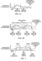
- FIGURE 4A is a timing diagram for continuous environment monitoring according to an exemplary embodiment of the present invention
- FIGURE 4B is a timing diagram for discontinuous environment monitoring according to an exemplary embodiment of the present invention. It should be understood, however, that the environment monitoring of FIGURE 4A and/or FIGURE 4B as illustrated and hereinafter described is merely illustrative of environment monitoring which may be employed to evaluate environmental conditions, and therefore, should not be taken to limit the scope of the present invention.
- FIGURE 4A illustrates a varying environmental unfavorableness over time in relation to an environmental unfavorableness threshold 404.
- environmental unfavorableness may be continuously monitored.
- a disruption start time 406 relates to the time when the environmental unfavorableness becomes outside the environmental unfavorableness threshold 404.
- a disruption stop time 408 relates to the time when the environmental unfavorableness becomes within the environmental unfavorableness threshold 404.
- FIGURE 4B illustrates an exemplary embodiment where environmental monitoring is performed discontinuously by using a sampling method.
- This sampling method may comprise one or more sampling times 454, which may occur at various times during operation of a device, for example, mobile terminal 10 of FIGURE 1 ,.
- sampling times 454 may occur at various times during operation of a device, for example, mobile terminal 10 of FIGURE 1 .
- there may be various strategies for determining time intervals between samples For example, there may be a fixed amount of time between each sample. In another example, there may be less time between samples when environmental unfavorableness is near an environmental unfavorableness threshold 456.
- Disruption start time A 458 relates to the time when the environmental unfavorableness becomes outside the environmental unfavorableness threshold 456.
- Disruption stop time A 460 relates to the time when the environmental unfavorableness becomes within the environmental unfavorableness threshold 456.
- Disruption start time B 462 relates to the time when the environmental unfavorableness becomes outside the environmental unfavorableness threshold 456.
- Disruption stop time B 464 relates to the time when the environmental unfavorableness becomes within the environmental unfavorableness threshold 456.
- disruption start time A 458, disruption stop time A 460, and disruption stop time B 464 are represented later than the times when environmental unfavorableness crosses the environmental unfavorableness threshold 456.
- Such late determinations may be related to the discontinuous nature of the sampling method.
- events may be stored during times of environmental unfavorableness so that a user may be alerted at a later time. This later time may be, for example, when a time of environmental favorableness is entered, a time after environment unfavorableness is entered, etc.
- an event storage window may refer to a time period between starting event storage and generating an alert of at least one stored event. However, it should be understood that events may continue to be stored after the alert of at least one stored event.
- a missed alert may comprise an alert for a phone call event where the user does not answer the call, an alert for a phone call event where the user does not decline the call or answer the call, a message alert where the message is not read within a certain amount of time, and/or the like.
- Handling of an alert may comprise a user answering an alert for a phone call, a user declining an alert for a phone call, a user reading a message and/or the like.
- FIGURE 5 is a timing diagram of an event storage mode according to an exemplary embodiment of the present invention. It should be understood, however, that the event storage mode of FIGURE 5 as illustrated and hereinafter described is merely illustrative of event storage mode which may be employed, and therefore, should not be taken to limit the scope of the present invention.
- event storage relates to storage of any information related to an event. This information may comprise alert information, event type information, metadata information, and/or the like.
- an event storage start 506 relates to an environmental unfavorableness becoming outside an environmental unfavorableness threshold 504. While the environmental unfavorableness is outside of the environmental unfavorableness threshold, event A 512 and event B 514 occur. In an exemplary embodiment, events occurring after an event storage start 506 are stored. Thus in FIGURE 5 , event A 512 and event B 514 which occur after event storage start 506 are stored. After the environmental unfavorableness becomes within the environmental unfavorableness threshold 504 a stored event alert 510 may be generated. The stored event alert may comprise information related to event A 512, event B 514, any previously unhandled event, and/or the like. In an exemplary embodiment, an event storage window 508 relates to the time between event storage start 506 and stored event alert 510.
- FIGURE 6 is a flow chart of a method for storing events according to an exemplary embodiment of the present invention. It should be understood, however, that the method for storing eventsof FIGURE 6 as illustrated and hereinafter described is merely illustrative of an event storage method which may be employed, and therefore, should not be taken to limit the scope of the present invention.
- the environment around a device is checked or monitored.
- the check may comprise evaluating information from one or more environment monitoring systems, for example environment monitoring system 300 of FIGURE 3 .
- monitoring the environment at block 602 may comprise: a discrete operation, a set of operations, a notification from another system, and/or the like.
- the checking or monitoring may comprise continuous monitoring such as illustrated in FIGURE 4A and/or discontinuous monitoring as illustrated in FIGURE 4B .
- this check may comprise relating environmental information to one or more environmental unfavorableness thresholds.
- a determination is made as to whether an event has been received is performed. This determination may comprise an active check, a notification, and/or the like.
- a telephony module may send a notification which relates to occurrence of an event such as a phone call.
- determination of an event occurrence may be performed by querying a telephony module about occurrence of an event, such as a phone call.
- an event storage structure may comprise at least in part: a tree, linked list, database, and/or the like.
- FIGURE 7 is a timing diagram of an event storage mode related to receiving an event according to an exemplary embodiment of the present invention. It should be understood, however, that the event storage mode of FIGURE 7 as illustrated and hereinafter described is merely illustrative of an event storage mode which may be employed, and therefore, should not be taken to limit the scope of the present invention.
- an event storage window 712 relates to the time between an event storage start 710 and a stored event alert 714.
- an event storage start 710 relates to an event A 706 occurring when environmental unfavorableness is outside an environmental unfavorableness threshold 704. Then event B 708 occurs.
- a stored event alert 714 may be generated in relation to the environmental unfavorableness becoming within the environmental unfavorableness threshold 704.
- the stored event alert may comprise information related to event A 706, event B 708, any previously unhandled events, and/or the like.
- the determination of the environmental unfavorableness being outside the environmental unfavorableness threshold may take place before an event, after an event, during the processing of an event, and/or the like. It can be seen in FIGURE 7 that the event storage start 710 coincides with event A 706, while in FIGURE 5 , the event storage start 506 coincides with the time when environmental unfavorableness becomes outside the environmental unfavorableness threshold 504.
- FIGURE 8A is a timing diagram of an event storage mode related to a user handling an alert according to an exemplary embodiment of the present invention. It should be understood, however, that the event storage mode of FIGURE 8A as illustrated and hereinafter described is merely illustrative of an event storage mode which may be employed, and therefore, should not be taken to limit the scope of the present invention.
- an event storage start 806 relates to an environmental unfavorableness becoming outside an environmental unfavorableness threshold 804. Then event A 812 occurs and event B 814 occurs.
- a stored event alert 808 may be generated in relation to an environmental factor, for example, the environmental unfavorableness becoming within the environmental unfavorableness threshold 804.
- the stored event alert may comprise information related to event A 812, event B 814, any previously unhandled events, and/or the like.
- the user handles the alert 816.
- an event storage window 810 relates to the time between event storage start 806 and a user handling the alert 816. Handling of an alert may comprise a user answering an alert for a phone call, a user declining an alert for a phone call, a user reading a message and/or the like.
- FIGURE 8B is a timing diagram illustrating operation of an event storage mode related to more than one period of environmental unfavorableness according to an exemplary embodiment of the present invention. It should be understood, however, that the event storage mode of FIGURE 8B as illustrated and hereinafter described is merely illustrative of an event storage mode which may be employed, and therefore, should not be taken to limit the scope of the present invention.
- an event storage start 856 relates to an environmental unfavorableness becoming outside an environmental unfavorableness threshold 854.
- Event A 866 occurs after event storage start 856.
- a stored event alert 858 may be generated in relation to the environmental unfavorableness becoming within the environmental unfavorableness threshold 854.
- the stored event alert may comprise information related to event A 866, any previously unhandled events, and/or the like.
- a stored event alert 860 may be generated in relation to the environmental unfavorableness again becoming within the environmental unfavorableness threshold 854.
- the stored event alert may comprise information related to event A 866, any previously unhandled events, and/or the like. After the environmental unfavorableness again becomes outside the environmental unfavorableness threshold 854, event B 868 occurs.
- a stored event alert 862 may be generated in relation to the environmental unfavorableness again becoming within the environmental unfavorableness threshold 854.
- the stored event alert may comprise information related to event A 866, event B 868, any previously unhandled events, and/or the like.
- the user handles the alert 816.
- an event storage window 864 relates to the time between event storage start 856 and a user handling the alert 870. It can be seen that the event storage window 864 may relate to multiple events occurring across multiple time periods where environmental unfavorableness is outside the environmental unfavorableness threshold 854.
- environmental unfavorableness may be determined and/or utilized. It should be further understood that in cases where environmental favorableness is determined and/or utilized, if desired, environmental unfavorableness may be determined and/or utilized. It should also be understood that information containing ratings of environmental favorableness and/or environmental unfavorableness may be at least a partial basis for other values related to environmental favorableness and/or environmental unfavorableness.
- an environmental unfavorableness may be determined to be within an environmental unfavorableness threshold if the environmental unfavorableness is less than an environmental unfavorableness threshold.
- an environmental unfavorableness may be determined to be outside an environmental unfavorableness threshold if the environmental unfavorableness is less than an environmental unfavorableness threshold.
- Embodiments of the present invention may be implemented in software, hardware, application logic or a combination of software, hardware and/or application logic.
- the software, application logic and/or hardware may reside on a single or a plurality of devices. If desired, part of the software, application logic and/or hardware may reside on a device, part of the software, application logic and/or hardware may reside on another part of the device, and part of the software, application logic and/or hardware may reside on a different device.
- the application logic, software or an instruction set is preferably maintained on any one of various conventional computer-readable media.
- a "computer-readable medium" may be any media or means that may contain, store, communicate, propagate or transport the instructions for use by or in connection with an instruction execution system, apparatus, or device.
- the different functions discussed herein may be performed in any order and/or concurrently with each other. Furthermore, if desired, one or more of the above-described functions may be optional or may be combined.
- a technical advantage of one or more of the exemplary embodiments disclosed herein may be repeating an alert when environmental conditions may have interfered with user perception of the alert. Another possible technical advantage of one or more of the exemplary embodiments disclosed herein may be allowing timing of an alert to be at least partially related to environmental conditions. Another technical advantage of one or more of the exemplary embodiments disclosed herein may be increasing the likelihood that a user will perceive an alert.
Priority Applications (1)
| Application Number | Priority Date | Filing Date | Title |
|---|---|---|---|
| PL08854999T PL2215821T3 (pl) | 2007-11-30 | 2008-12-01 | Sposób i urządzenie do sterowania powiadomieniami |
Applications Claiming Priority (2)
| Application Number | Priority Date | Filing Date | Title |
|---|---|---|---|
| US11/948,642 US20090140853A1 (en) | 2007-11-30 | 2007-11-30 | Method and Apparatus for Alert Control |
| PCT/IB2008/003297 WO2009068986A1 (en) | 2007-11-30 | 2008-12-01 | Method and apparatus for alert control |
Publications (2)
| Publication Number | Publication Date |
|---|---|
| EP2215821A1 EP2215821A1 (en) | 2010-08-11 |
| EP2215821B1 true EP2215821B1 (en) | 2015-08-12 |
Family
ID=40386341
Family Applications (1)
| Application Number | Title | Priority Date | Filing Date |
|---|---|---|---|
| EP08854999.3A Active EP2215821B1 (en) | 2007-11-30 | 2008-12-01 | Method and apparatus for alert control |
Country Status (6)
| Country | Link |
|---|---|
| US (1) | US20090140853A1 (es) |
| EP (1) | EP2215821B1 (es) |
| CN (2) | CN101878639A (es) |
| ES (1) | ES2551118T3 (es) |
| PL (1) | PL2215821T3 (es) |
| WO (1) | WO2009068986A1 (es) |
Families Citing this family (40)
| Publication number | Priority date | Publication date | Assignee | Title |
|---|---|---|---|---|
| CN101252680A (zh) * | 2008-04-14 | 2008-08-27 | 中兴通讯股份有限公司 | 一种采用不同监控精度进行监控的方法及终端 |
| US8487759B2 (en) | 2009-09-30 | 2013-07-16 | Apple Inc. | Self adapting haptic device |
| US8301121B2 (en) | 2010-01-22 | 2012-10-30 | Sony Ericsson Mobile Communications Ab | Regulating alerts generated by communication terminals responsive to sensed movement |
| US8384552B2 (en) * | 2010-06-08 | 2013-02-26 | Nucsafe, Inc. | Radiation portal with occupancy and motion sensing system |
| US10013058B2 (en) | 2010-09-21 | 2018-07-03 | Apple Inc. | Touch-based user interface with haptic feedback |
| US10120446B2 (en) | 2010-11-19 | 2018-11-06 | Apple Inc. | Haptic input device |
| CN103312878B (zh) * | 2012-03-13 | 2015-09-02 | 宇龙计算机通信科技(深圳)有限公司 | 一种事务管理方法和移动终端 |
| CN102700718B (zh) * | 2012-06-29 | 2014-04-16 | 中国航空工业集团公司第六三一研究所 | 通用飞机航空电子系统告警信息处理方法 |
| US9178509B2 (en) | 2012-09-28 | 2015-11-03 | Apple Inc. | Ultra low travel keyboard |
| CN103051810B (zh) * | 2013-01-05 | 2015-06-24 | 小米科技有限责任公司 | 一种信息提醒的方法及移动终端 |
| WO2014128021A1 (en) * | 2013-02-19 | 2014-08-28 | Thomson Licensing | Method and apparatus for notifying missed events |
| CN104104775B (zh) * | 2013-04-02 | 2018-06-01 | 中兴通讯股份有限公司 | 一种自动调整手机振铃音量和振动方式的方法及装置 |
| US9652040B2 (en) | 2013-08-08 | 2017-05-16 | Apple Inc. | Sculpted waveforms with no or reduced unforced response |
| US9779592B1 (en) | 2013-09-26 | 2017-10-03 | Apple Inc. | Geared haptic feedback element |
| US9928950B2 (en) | 2013-09-27 | 2018-03-27 | Apple Inc. | Polarized magnetic actuators for haptic response |
| CN105579928A (zh) | 2013-09-27 | 2016-05-11 | 苹果公司 | 具有触觉致动器的带体 |
| WO2015047364A1 (en) | 2013-09-29 | 2015-04-02 | Pearl Capital Developments Llc | Devices and methods for creating haptic effects |
| CN105683865B (zh) | 2013-09-30 | 2018-11-09 | 苹果公司 | 用于触觉响应的磁性致动器 |
| US9317118B2 (en) | 2013-10-22 | 2016-04-19 | Apple Inc. | Touch surface for simulating materials |
| WO2015088491A1 (en) | 2013-12-10 | 2015-06-18 | Bodhi Technology Ventures Llc | Band attachment mechanism with haptic response |
| US9501912B1 (en) | 2014-01-27 | 2016-11-22 | Apple Inc. | Haptic feedback device with a rotating mass of variable eccentricity |
| WO2015135748A1 (en) * | 2014-03-11 | 2015-09-17 | Sony Corporation | Methods and devices for situation-adequate notifications |
| WO2015163842A1 (en) | 2014-04-21 | 2015-10-29 | Yknots Industries Llc | Apportionment of forces for multi-touch input devices of electronic devices |
| DE102015209639A1 (de) | 2014-06-03 | 2015-12-03 | Apple Inc. | Linearer Aktuator |
| KR102019505B1 (ko) | 2014-09-02 | 2019-09-06 | 애플 인크. | 햅틱 통지 |
| CN105516442A (zh) * | 2014-09-25 | 2016-04-20 | 宇龙计算机通信科技(深圳)有限公司 | 一种事件提醒方法及移动终端 |
| US10353467B2 (en) | 2015-03-06 | 2019-07-16 | Apple Inc. | Calibration of haptic devices |
| AU2016100399B4 (en) | 2015-04-17 | 2017-02-02 | Apple Inc. | Contracting and elongating materials for providing input and output for an electronic device |
| WO2017044618A1 (en) | 2015-09-08 | 2017-03-16 | Apple Inc. | Linear actuators for use in electronic devices |
| US9955235B2 (en) * | 2015-12-15 | 2018-04-24 | Sony Corporation | System and method to communicate an emergency alert message |
| US10039080B2 (en) | 2016-03-04 | 2018-07-31 | Apple Inc. | Situationally-aware alerts |
| US10268272B2 (en) | 2016-03-31 | 2019-04-23 | Apple Inc. | Dampening mechanical modes of a haptic actuator using a delay |
| CN107071199A (zh) * | 2017-04-19 | 2017-08-18 | 珠海市魅族科技有限公司 | 通知铃音的控制方法以及终端设备 |
| US10622538B2 (en) | 2017-07-18 | 2020-04-14 | Apple Inc. | Techniques for providing a haptic output and sensing a haptic input using a piezoelectric body |
| US10599223B1 (en) | 2018-09-28 | 2020-03-24 | Apple Inc. | Button providing force sensing and/or haptic output |
| US10691211B2 (en) | 2018-09-28 | 2020-06-23 | Apple Inc. | Button providing force sensing and/or haptic output |
| CN109361822A (zh) * | 2018-12-28 | 2019-02-19 | 努比亚技术有限公司 | 来电提醒方法、移动终端和计算机可读存储介质 |
| US11380470B2 (en) | 2019-09-24 | 2022-07-05 | Apple Inc. | Methods to control force in reluctance actuators based on flux related parameters |
| US11977683B2 (en) | 2021-03-12 | 2024-05-07 | Apple Inc. | Modular systems configured to provide localized haptic feedback using inertial actuators |
| US11809631B2 (en) | 2021-09-21 | 2023-11-07 | Apple Inc. | Reluctance haptic engine for an electronic device |
Family Cites Families (15)
| Publication number | Priority date | Publication date | Assignee | Title |
|---|---|---|---|---|
| US6408187B1 (en) * | 1999-05-14 | 2002-06-18 | Sun Microsystems, Inc. | Method and apparatus for determining the behavior of a communications device based upon environmental conditions |
| US6650902B1 (en) * | 1999-11-15 | 2003-11-18 | Lucent Technologies Inc. | Method and apparatus for wireless telecommunications system that provides location-based information delivery to a wireless mobile unit |
| US8086672B2 (en) * | 2000-06-17 | 2011-12-27 | Microsoft Corporation | When-free messaging |
| CN1233115C (zh) * | 2000-06-30 | 2005-12-21 | 德克萨斯仪器股份有限公司 | 具有智能告警系统的无线通信设备 |
| US6954657B2 (en) * | 2000-06-30 | 2005-10-11 | Texas Instruments Incorporated | Wireless communication device having intelligent alerting system |
| US6993349B2 (en) * | 2001-07-18 | 2006-01-31 | Kyocera Wireless Corp. | Smart ringer |
| AU2002345285A1 (en) * | 2002-07-11 | 2004-02-02 | Nokia Corporation | Method and device for automatically changing a digital content on a mobile device according to sensor data |
| US20040127198A1 (en) * | 2002-12-30 | 2004-07-01 | Roskind James A. | Automatically changing a mobile device configuration based on environmental condition |
| US20050255826A1 (en) * | 2004-05-12 | 2005-11-17 | Wittenburg Kent B | Cellular telephone based surveillance system |
| US7469155B2 (en) * | 2004-11-29 | 2008-12-23 | Cisco Technology, Inc. | Handheld communications device with automatic alert mode selection |
| KR100621017B1 (ko) * | 2004-12-03 | 2006-09-19 | 엘지전자 주식회사 | 휴대 단말기 위치에 따른 알람 설정 변경 방법 |
| US7333604B2 (en) * | 2005-01-10 | 2008-02-19 | Infone Tech, Ltd. | Adaptive notification of an incoming call in a mobile phone |
| CN100403830C (zh) * | 2006-02-23 | 2008-07-16 | 华为技术有限公司 | 一种实现用户终端提示用户查看信息的方法及装置 |
| US8050665B1 (en) * | 2006-10-20 | 2011-11-01 | Avaya Inc. | Alert reminder trigger by motion-detector |
| US20080132290A1 (en) * | 2006-11-30 | 2008-06-05 | Motorola, Inc. | Methods and devices for environmental triggering of missed message alerts |
-
2007
- 2007-11-30 US US11/948,642 patent/US20090140853A1/en not_active Abandoned
-
2008
- 2008-12-01 EP EP08854999.3A patent/EP2215821B1/en active Active
- 2008-12-01 PL PL08854999T patent/PL2215821T3/pl unknown
- 2008-12-01 CN CN2008801181897A patent/CN101878639A/zh active Pending
- 2008-12-01 CN CN201610105804.7A patent/CN105791555A/zh active Pending
- 2008-12-01 WO PCT/IB2008/003297 patent/WO2009068986A1/en active Application Filing
- 2008-12-01 ES ES08854999.3T patent/ES2551118T3/es active Active
Also Published As
| Publication number | Publication date |
|---|---|
| CN101878639A (zh) | 2010-11-03 |
| ES2551118T3 (es) | 2015-11-16 |
| US20090140853A1 (en) | 2009-06-04 |
| PL2215821T3 (pl) | 2016-01-29 |
| WO2009068986A1 (en) | 2009-06-04 |
| CN105791555A (zh) | 2016-07-20 |
| EP2215821A1 (en) | 2010-08-11 |
Similar Documents
| Publication | Publication Date | Title |
|---|---|---|
| EP2215821B1 (en) | Method and apparatus for alert control | |
| US20130066815A1 (en) | System and method for mobile context determination | |
| KR20090127881A (ko) | 사용자 상태 표시자 제공 방법, 컴퓨터 판독가능한 저장 매체 및 사용자 상태 표시자 제공 장치 | |
| EP3334127A1 (en) | Message pushing method and apparatus thereof | |
| US10491745B2 (en) | Process for real-time data exchange between users on a phone call | |
| CN106055364A (zh) | 一种启动应用方法及终端设备 | |
| EP2701302B1 (en) | Amethod and apparatus for controlling vibration intensity according to situation awareness in electronic device | |
| EP2844007B1 (en) | Method for transmitting contents and electronic device thereof | |
| KR101747571B1 (ko) | 메모리 최적화 방법, 장치, 프로그램 및 기록매체 | |
| CN105812601A (zh) | 振动提醒控制方法、装置和终端设备 | |
| US20190373114A1 (en) | System and method for controlling notifications in an electronic device according to user status | |
| EP1971120B1 (en) | Method and apparatus for automatically adjusting reminder volume on a mobile communication device | |
| CN112261225A (zh) | 音量调节方法、装置、电子设备和存储介质 | |
| US20090276412A1 (en) | Method, apparatus, and computer program product for providing usage analysis | |
| EP2344963A1 (en) | Method, apparatus and computer program product for enabling dual mode communication | |
| KR20150019813A (ko) | 컨텐츠 무결성 제어 방법 및 그 전자 장치 | |
| CN105474146B (zh) | 电子装置和控制电子装置的触摸反应的方法 | |
| US9681005B2 (en) | Mobile communication device and prompting method thereof | |
| CN106445491A (zh) | 一种图片切换方法及终端设备 | |
| US20090276855A1 (en) | Method, apparatus, and computer program product that provide for presentation of event items | |
| CN104793847B (zh) | 图片展示方法及装置 | |
| EP2571292B1 (en) | System and method for mobile context determination | |
| KR102008493B1 (ko) | 점수 기반의 보안 강화 장치 및 방법 | |
| US20130023256A1 (en) | Communication device and method using same | |
| CN111213355A (zh) | 一种信息处理方法及终端 |
Legal Events
| Date | Code | Title | Description |
|---|---|---|---|
| PUAI | Public reference made under article 153(3) epc to a published international application that has entered the european phase |
Free format text: ORIGINAL CODE: 0009012 |
|
| 17P | Request for examination filed |
Effective date: 20100209 |
|
| AK | Designated contracting states |
Kind code of ref document: A1 Designated state(s): AT BE BG CH CY CZ DE DK EE ES FI FR GB GR HR HU IE IS IT LI LT LU LV MC MT NL NO PL PT RO SE SI SK TR |
|
| AX | Request for extension of the european patent |
Extension state: AL BA MK RS |
|
| DAX | Request for extension of the european patent (deleted) | ||
| 17Q | First examination report despatched |
Effective date: 20131112 |
|
| RAP1 | Party data changed (applicant data changed or rights of an application transferred) |
Owner name: NOKIA CORPORATION |
|
| GRAP | Despatch of communication of intention to grant a patent |
Free format text: ORIGINAL CODE: EPIDOSNIGR1 |
|
| INTG | Intention to grant announced |
Effective date: 20150219 |
|
| RAP1 | Party data changed (applicant data changed or rights of an application transferred) |
Owner name: NOKIA TECHNOLOGIES OY |
|
| GRAS | Grant fee paid |
Free format text: ORIGINAL CODE: EPIDOSNIGR3 |
|
| GRAA | (expected) grant |
Free format text: ORIGINAL CODE: 0009210 |
|
| AK | Designated contracting states |
Kind code of ref document: B1 Designated state(s): AT BE BG CH CY CZ DE DK EE ES FI FR GB GR HR HU IE IS IT LI LT LU LV MC MT NL NO PL PT RO SE SI SK TR |
|
| REG | Reference to a national code |
Ref country code: GB Ref legal event code: FG4D |
|
| REG | Reference to a national code |
Ref country code: CH Ref legal event code: EP |
|
| REG | Reference to a national code |
Ref country code: AT Ref legal event code: REF Ref document number: 743023 Country of ref document: AT Kind code of ref document: T Effective date: 20150815 |
|
| REG | Reference to a national code |
Ref country code: IE Ref legal event code: FG4D |
|
| REG | Reference to a national code |
Ref country code: DE Ref legal event code: R096 Ref document number: 602008039570 Country of ref document: DE |
|
| REG | Reference to a national code |
Ref country code: FR Ref legal event code: PLFP Year of fee payment: 8 |
|
| REG | Reference to a national code |
Ref country code: ES Ref legal event code: FG2A Ref document number: 2551118 Country of ref document: ES Kind code of ref document: T3 Effective date: 20151116 |
|
| REG | Reference to a national code |
Ref country code: LT Ref legal event code: MG4D |
|
| REG | Reference to a national code |
Ref country code: AT Ref legal event code: MK05 Ref document number: 743023 Country of ref document: AT Kind code of ref document: T Effective date: 20150812 |
|
| REG | Reference to a national code |
Ref country code: NL Ref legal event code: FP |
|
| PG25 | Lapsed in a contracting state [announced via postgrant information from national office to epo] |
Ref country code: GR Free format text: LAPSE BECAUSE OF FAILURE TO SUBMIT A TRANSLATION OF THE DESCRIPTION OR TO PAY THE FEE WITHIN THE PRESCRIBED TIME-LIMIT Effective date: 20151113 Ref country code: FI Free format text: LAPSE BECAUSE OF FAILURE TO SUBMIT A TRANSLATION OF THE DESCRIPTION OR TO PAY THE FEE WITHIN THE PRESCRIBED TIME-LIMIT Effective date: 20150812 Ref country code: LT Free format text: LAPSE BECAUSE OF FAILURE TO SUBMIT A TRANSLATION OF THE DESCRIPTION OR TO PAY THE FEE WITHIN THE PRESCRIBED TIME-LIMIT Effective date: 20150812 Ref country code: NO Free format text: LAPSE BECAUSE OF FAILURE TO SUBMIT A TRANSLATION OF THE DESCRIPTION OR TO PAY THE FEE WITHIN THE PRESCRIBED TIME-LIMIT Effective date: 20151112 Ref country code: LV Free format text: LAPSE BECAUSE OF FAILURE TO SUBMIT A TRANSLATION OF THE DESCRIPTION OR TO PAY THE FEE WITHIN THE PRESCRIBED TIME-LIMIT Effective date: 20150812 |
|
| PG25 | Lapsed in a contracting state [announced via postgrant information from national office to epo] |
Ref country code: PT Free format text: LAPSE BECAUSE OF FAILURE TO SUBMIT A TRANSLATION OF THE DESCRIPTION OR TO PAY THE FEE WITHIN THE PRESCRIBED TIME-LIMIT Effective date: 20151214 Ref country code: HR Free format text: LAPSE BECAUSE OF FAILURE TO SUBMIT A TRANSLATION OF THE DESCRIPTION OR TO PAY THE FEE WITHIN THE PRESCRIBED TIME-LIMIT Effective date: 20150812 Ref country code: IS Free format text: LAPSE BECAUSE OF FAILURE TO SUBMIT A TRANSLATION OF THE DESCRIPTION OR TO PAY THE FEE WITHIN THE PRESCRIBED TIME-LIMIT Effective date: 20151212 Ref country code: SE Free format text: LAPSE BECAUSE OF FAILURE TO SUBMIT A TRANSLATION OF THE DESCRIPTION OR TO PAY THE FEE WITHIN THE PRESCRIBED TIME-LIMIT Effective date: 20150812 Ref country code: AT Free format text: LAPSE BECAUSE OF FAILURE TO SUBMIT A TRANSLATION OF THE DESCRIPTION OR TO PAY THE FEE WITHIN THE PRESCRIBED TIME-LIMIT Effective date: 20150812 |
|
| PG25 | Lapsed in a contracting state [announced via postgrant information from national office to epo] |
Ref country code: DK Free format text: LAPSE BECAUSE OF FAILURE TO SUBMIT A TRANSLATION OF THE DESCRIPTION OR TO PAY THE FEE WITHIN THE PRESCRIBED TIME-LIMIT Effective date: 20150812 Ref country code: SK Free format text: LAPSE BECAUSE OF FAILURE TO SUBMIT A TRANSLATION OF THE DESCRIPTION OR TO PAY THE FEE WITHIN THE PRESCRIBED TIME-LIMIT Effective date: 20150812 Ref country code: CZ Free format text: LAPSE BECAUSE OF FAILURE TO SUBMIT A TRANSLATION OF THE DESCRIPTION OR TO PAY THE FEE WITHIN THE PRESCRIBED TIME-LIMIT Effective date: 20150812 Ref country code: IT Free format text: LAPSE BECAUSE OF FAILURE TO SUBMIT A TRANSLATION OF THE DESCRIPTION OR TO PAY THE FEE WITHIN THE PRESCRIBED TIME-LIMIT Effective date: 20150812 Ref country code: EE Free format text: LAPSE BECAUSE OF FAILURE TO SUBMIT A TRANSLATION OF THE DESCRIPTION OR TO PAY THE FEE WITHIN THE PRESCRIBED TIME-LIMIT Effective date: 20150812 |
|
| REG | Reference to a national code |
Ref country code: DE Ref legal event code: R097 Ref document number: 602008039570 Country of ref document: DE |
|
| PG25 | Lapsed in a contracting state [announced via postgrant information from national office to epo] |
Ref country code: RO Free format text: LAPSE BECAUSE OF FAILURE TO SUBMIT A TRANSLATION OF THE DESCRIPTION OR TO PAY THE FEE WITHIN THE PRESCRIBED TIME-LIMIT Effective date: 20150812 Ref country code: BE Free format text: LAPSE BECAUSE OF NON-PAYMENT OF DUE FEES Effective date: 20151231 |
|
| PLBE | No opposition filed within time limit |
Free format text: ORIGINAL CODE: 0009261 |
|
| STAA | Information on the status of an ep patent application or granted ep patent |
Free format text: STATUS: NO OPPOSITION FILED WITHIN TIME LIMIT |
|
| 26N | No opposition filed |
Effective date: 20160513 |
|
| PG25 | Lapsed in a contracting state [announced via postgrant information from national office to epo] |
Ref country code: MC Free format text: LAPSE BECAUSE OF FAILURE TO SUBMIT A TRANSLATION OF THE DESCRIPTION OR TO PAY THE FEE WITHIN THE PRESCRIBED TIME-LIMIT Effective date: 20150812 Ref country code: LU Free format text: LAPSE BECAUSE OF FAILURE TO SUBMIT A TRANSLATION OF THE DESCRIPTION OR TO PAY THE FEE WITHIN THE PRESCRIBED TIME-LIMIT Effective date: 20151201 |
|
| REG | Reference to a national code |
Ref country code: CH Ref legal event code: PL |
|
| PG25 | Lapsed in a contracting state [announced via postgrant information from national office to epo] |
Ref country code: SI Free format text: LAPSE BECAUSE OF FAILURE TO SUBMIT A TRANSLATION OF THE DESCRIPTION OR TO PAY THE FEE WITHIN THE PRESCRIBED TIME-LIMIT Effective date: 20150812 |
|
| REG | Reference to a national code |
Ref country code: IE Ref legal event code: MM4A |
|
| PG25 | Lapsed in a contracting state [announced via postgrant information from national office to epo] |
Ref country code: IE Free format text: LAPSE BECAUSE OF NON-PAYMENT OF DUE FEES Effective date: 20151201 Ref country code: LI Free format text: LAPSE BECAUSE OF NON-PAYMENT OF DUE FEES Effective date: 20151231 Ref country code: CH Free format text: LAPSE BECAUSE OF NON-PAYMENT OF DUE FEES Effective date: 20151231 |
|
| REG | Reference to a national code |
Ref country code: FR Ref legal event code: PLFP Year of fee payment: 9 |
|
| PG25 | Lapsed in a contracting state [announced via postgrant information from national office to epo] |
Ref country code: BE Free format text: LAPSE BECAUSE OF FAILURE TO SUBMIT A TRANSLATION OF THE DESCRIPTION OR TO PAY THE FEE WITHIN THE PRESCRIBED TIME-LIMIT Effective date: 20150812 |
|
| PG25 | Lapsed in a contracting state [announced via postgrant information from national office to epo] |
Ref country code: BG Free format text: LAPSE BECAUSE OF FAILURE TO SUBMIT A TRANSLATION OF THE DESCRIPTION OR TO PAY THE FEE WITHIN THE PRESCRIBED TIME-LIMIT Effective date: 20150812 Ref country code: HU Free format text: LAPSE BECAUSE OF FAILURE TO SUBMIT A TRANSLATION OF THE DESCRIPTION OR TO PAY THE FEE WITHIN THE PRESCRIBED TIME-LIMIT; INVALID AB INITIO Effective date: 20081201 |
|
| PG25 | Lapsed in a contracting state [announced via postgrant information from national office to epo] |
Ref country code: CY Free format text: LAPSE BECAUSE OF FAILURE TO SUBMIT A TRANSLATION OF THE DESCRIPTION OR TO PAY THE FEE WITHIN THE PRESCRIBED TIME-LIMIT Effective date: 20150812 |
|
| PG25 | Lapsed in a contracting state [announced via postgrant information from national office to epo] |
Ref country code: TR Free format text: LAPSE BECAUSE OF FAILURE TO SUBMIT A TRANSLATION OF THE DESCRIPTION OR TO PAY THE FEE WITHIN THE PRESCRIBED TIME-LIMIT Effective date: 20150812 Ref country code: MT Free format text: LAPSE BECAUSE OF FAILURE TO SUBMIT A TRANSLATION OF THE DESCRIPTION OR TO PAY THE FEE WITHIN THE PRESCRIBED TIME-LIMIT Effective date: 20150812 |
|
| REG | Reference to a national code |
Ref country code: FR Ref legal event code: PLFP Year of fee payment: 10 |
|
| PGFP | Annual fee paid to national office [announced via postgrant information from national office to epo] |
Ref country code: NL Payment date: 20191114 Year of fee payment: 12 |
|
| PGFP | Annual fee paid to national office [announced via postgrant information from national office to epo] |
Ref country code: PL Payment date: 20191119 Year of fee payment: 12 |
|
| REG | Reference to a national code |
Ref country code: NL Ref legal event code: MM Effective date: 20210101 |
|
| PG25 | Lapsed in a contracting state [announced via postgrant information from national office to epo] |
Ref country code: NL Free format text: LAPSE BECAUSE OF NON-PAYMENT OF DUE FEES Effective date: 20210101 |
|
| PG25 | Lapsed in a contracting state [announced via postgrant information from national office to epo] |
Ref country code: PL Free format text: LAPSE BECAUSE OF NON-PAYMENT OF DUE FEES Effective date: 20201201 |
|
| PGFP | Annual fee paid to national office [announced via postgrant information from national office to epo] |
Ref country code: ES Payment date: 20230113 Year of fee payment: 15 |
|
| P01 | Opt-out of the competence of the unified patent court (upc) registered |
Effective date: 20230527 |
|
| PGFP | Annual fee paid to national office [announced via postgrant information from national office to epo] |
Ref country code: GB Payment date: 20231102 Year of fee payment: 16 |
|
| PGFP | Annual fee paid to national office [announced via postgrant information from national office to epo] |
Ref country code: FR Payment date: 20231108 Year of fee payment: 16 Ref country code: DE Payment date: 20231031 Year of fee payment: 16 |
|
| PGFP | Annual fee paid to national office [announced via postgrant information from national office to epo] |
Ref country code: ES Payment date: 20240118 Year of fee payment: 16 |