EP2215346B1 - High gas inlet temperature egr system - Google Patents
High gas inlet temperature egr system Download PDFInfo
- Publication number
- EP2215346B1 EP2215346B1 EP08788275A EP08788275A EP2215346B1 EP 2215346 B1 EP2215346 B1 EP 2215346B1 EP 08788275 A EP08788275 A EP 08788275A EP 08788275 A EP08788275 A EP 08788275A EP 2215346 B1 EP2215346 B1 EP 2215346B1
- Authority
- EP
- European Patent Office
- Prior art keywords
- tubular member
- cooling device
- inner tubular
- exhaust gas
- corrugations
- Prior art date
- Legal status (The legal status is an assumption and is not a legal conclusion. Google has not performed a legal analysis and makes no representation as to the accuracy of the status listed.)
- Active
Links
Images


Classifications
-
- F—MECHANICAL ENGINEERING; LIGHTING; HEATING; WEAPONS; BLASTING
- F28—HEAT EXCHANGE IN GENERAL
- F28F—DETAILS OF HEAT-EXCHANGE AND HEAT-TRANSFER APPARATUS, OF GENERAL APPLICATION
- F28F1/00—Tubular elements; Assemblies of tubular elements
- F28F1/08—Tubular elements crimped or corrugated in longitudinal section
-
- F—MECHANICAL ENGINEERING; LIGHTING; HEATING; WEAPONS; BLASTING
- F02—COMBUSTION ENGINES; HOT-GAS OR COMBUSTION-PRODUCT ENGINE PLANTS
- F02M—SUPPLYING COMBUSTION ENGINES IN GENERAL WITH COMBUSTIBLE MIXTURES OR CONSTITUENTS THEREOF
- F02M26/00—Engine-pertinent apparatus for adding exhaust gases to combustion-air, main fuel or fuel-air mixture, e.g. by exhaust gas recirculation [EGR] systems
- F02M26/13—Arrangement or layout of EGR passages, e.g. in relation to specific engine parts or for incorporation of accessories
- F02M26/22—Arrangement or layout of EGR passages, e.g. in relation to specific engine parts or for incorporation of accessories with coolers in the recirculation passage
- F02M26/29—Constructional details of the coolers, e.g. pipes, plates, ribs, insulation or materials
- F02M26/32—Liquid-cooled heat exchangers
-
- F—MECHANICAL ENGINEERING; LIGHTING; HEATING; WEAPONS; BLASTING
- F28—HEAT EXCHANGE IN GENERAL
- F28D—HEAT-EXCHANGE APPARATUS, NOT PROVIDED FOR IN ANOTHER SUBCLASS, IN WHICH THE HEAT-EXCHANGE MEDIA DO NOT COME INTO DIRECT CONTACT
- F28D7/00—Heat-exchange apparatus having stationary tubular conduit assemblies for both heat-exchange media, the media being in contact with different sides of a conduit wall
- F28D7/06—Heat-exchange apparatus having stationary tubular conduit assemblies for both heat-exchange media, the media being in contact with different sides of a conduit wall the conduits having a single U-bend
-
- F—MECHANICAL ENGINEERING; LIGHTING; HEATING; WEAPONS; BLASTING
- F28—HEAT EXCHANGE IN GENERAL
- F28D—HEAT-EXCHANGE APPARATUS, NOT PROVIDED FOR IN ANOTHER SUBCLASS, IN WHICH THE HEAT-EXCHANGE MEDIA DO NOT COME INTO DIRECT CONTACT
- F28D7/00—Heat-exchange apparatus having stationary tubular conduit assemblies for both heat-exchange media, the media being in contact with different sides of a conduit wall
- F28D7/10—Heat-exchange apparatus having stationary tubular conduit assemblies for both heat-exchange media, the media being in contact with different sides of a conduit wall the conduits being arranged one within the other, e.g. concentrically
- F28D7/106—Heat-exchange apparatus having stationary tubular conduit assemblies for both heat-exchange media, the media being in contact with different sides of a conduit wall the conduits being arranged one within the other, e.g. concentrically consisting of two coaxial conduits or modules of two coaxial conduits
-
- F—MECHANICAL ENGINEERING; LIGHTING; HEATING; WEAPONS; BLASTING
- F28—HEAT EXCHANGE IN GENERAL
- F28D—HEAT-EXCHANGE APPARATUS, NOT PROVIDED FOR IN ANOTHER SUBCLASS, IN WHICH THE HEAT-EXCHANGE MEDIA DO NOT COME INTO DIRECT CONTACT
- F28D7/00—Heat-exchange apparatus having stationary tubular conduit assemblies for both heat-exchange media, the media being in contact with different sides of a conduit wall
- F28D7/16—Heat-exchange apparatus having stationary tubular conduit assemblies for both heat-exchange media, the media being in contact with different sides of a conduit wall the conduits being arranged in parallel spaced relation
-
- F—MECHANICAL ENGINEERING; LIGHTING; HEATING; WEAPONS; BLASTING
- F02—COMBUSTION ENGINES; HOT-GAS OR COMBUSTION-PRODUCT ENGINE PLANTS
- F02M—SUPPLYING COMBUSTION ENGINES IN GENERAL WITH COMBUSTIBLE MIXTURES OR CONSTITUENTS THEREOF
- F02M26/00—Engine-pertinent apparatus for adding exhaust gases to combustion-air, main fuel or fuel-air mixture, e.g. by exhaust gas recirculation [EGR] systems
- F02M26/13—Arrangement or layout of EGR passages, e.g. in relation to specific engine parts or for incorporation of accessories
- F02M26/22—Arrangement or layout of EGR passages, e.g. in relation to specific engine parts or for incorporation of accessories with coolers in the recirculation passage
- F02M26/23—Layout, e.g. schematics
- F02M26/24—Layout, e.g. schematics with two or more coolers
-
- F—MECHANICAL ENGINEERING; LIGHTING; HEATING; WEAPONS; BLASTING
- F02—COMBUSTION ENGINES; HOT-GAS OR COMBUSTION-PRODUCT ENGINE PLANTS
- F02M—SUPPLYING COMBUSTION ENGINES IN GENERAL WITH COMBUSTIBLE MIXTURES OR CONSTITUENTS THEREOF
- F02M26/00—Engine-pertinent apparatus for adding exhaust gases to combustion-air, main fuel or fuel-air mixture, e.g. by exhaust gas recirculation [EGR] systems
- F02M26/13—Arrangement or layout of EGR passages, e.g. in relation to specific engine parts or for incorporation of accessories
- F02M26/22—Arrangement or layout of EGR passages, e.g. in relation to specific engine parts or for incorporation of accessories with coolers in the recirculation passage
- F02M26/23—Layout, e.g. schematics
- F02M26/25—Layout, e.g. schematics with coolers having bypasses
-
- F—MECHANICAL ENGINEERING; LIGHTING; HEATING; WEAPONS; BLASTING
- F28—HEAT EXCHANGE IN GENERAL
- F28F—DETAILS OF HEAT-EXCHANGE AND HEAT-TRANSFER APPARATUS, OF GENERAL APPLICATION
- F28F2265/00—Safety or protection arrangements; Arrangements for preventing malfunction
- F28F2265/26—Safety or protection arrangements; Arrangements for preventing malfunction for allowing differential expansion between elements
-
- F—MECHANICAL ENGINEERING; LIGHTING; HEATING; WEAPONS; BLASTING
- F28—HEAT EXCHANGE IN GENERAL
- F28F—DETAILS OF HEAT-EXCHANGE AND HEAT-TRANSFER APPARATUS, OF GENERAL APPLICATION
- F28F9/00—Casings; Header boxes; Auxiliary supports for elements; Auxiliary members within casings
- F28F9/02—Header boxes; End plates
- F28F9/0219—Arrangements for sealing end plates into casing or header box; Header box sub-elements
Definitions
- the present invention relates to gas cooling devices, and particularly although not exclusively to exhaust gas re-circulation coolers for use in automotive applications.
- Exhaust gas re-circulation cooling is used extensively on diesel engines to aid the reduction of nitrous oxide emissions, To aid overall emissions reduction, the EGR cooling on diesel engines may also be bypassed so that the re-circulated exhaust gas is not subject to additional cooling.
- heat exchange from the gas may be required, but under other circumstances it may be undesirable. For example in cold engine conditions, it is desirable not to additionally cool the gas so that the engine can heat up more quickly. Under hot engine conditions, it may be desirable to cool the gas.
- Exhaust gas re-circulation and the cooling of re-circulating exhaust gases can also be applied in gasoline (petrol) engines. This is of particular use when downsizing a gasoline engine and utilising turbo changing. Cooled exhaust gas re-circulation can help to significantly improve emissions whilst also reducing fuel consumption.
- a technical challenge of gasoline exhaust gas re-circulation cooling is that the exhaust gas at the inlet to the exhaust gas re-circutation system is much hotter than in the comparable situation with diesel engines.
- the temperature of re-circulated exhaust gas in a gasoline engine can be up to 1100 °C, but more typically up to around 1000 °C, compared to the equivalent situation in a diesel engine, where the gas temperature at the Inlet to the EGR system is typically of the order of up to 650 °C.
- a common failure mode of diesel exhaust gas re-circulation coolers is that thermal loading causes high stress at the gas inlet interface.
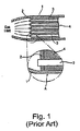
- FIG. 1 there is illustrated schematically in cut away view the inlet of a known exhaust gas re-circulation cooling device.
- the device comprises an outer casing 1 having a bulkhead 2 which extends across a width of the outer casing, the bulkhead contains a plurality of gas conduits 3.
- the outer casing 1 When gas flows the gas conduits expand due to their increased temperature from the gas, the outer casing 1 also expands but at a slower rate and has a thermal expansion which is less than the thermal expansion of the gas conduits, resulting in high stresses in the bulkhead and the gas conduits, for example as shown at position A in figure 1 .
- the result can include failure of the bulkheads, failure of the joints between the conduit tubes and the bulkhead, failure of tube to tube joints, and collapse of gas tubes.
- a typical failure of a tube to bulkhead joint may comprise a crack through the tubular conduit wall, at the position of the weld/braze between the tubular conduit wall and the bulkhead, resulting in mixture of coolant with the exhaust gas re-circulation path.
- EP1,770,250 discloses an exhaust gas cooler having inner and outer corrugated tubes forming a cavity there between in which liquid coolant flows to cool a gas flow through the inner tube.
- the problem addressed in EP1,770,250 is to replace prior art coolers for diesel engines, having a construction of a plurality of inner tubes and an outer casing, with a simpler structure.
- the solution presented in EP 1.770.250 is a concentric tube arrangement with a plurality of spacers to keep the tubes apart.
- the inner tube has a frusto - conical section joining the inner tube to the outer tube at the inlet end,
- the inlet ends of the inner and outer tubes do not coincide, and the Inlet of the outer tube extends beyond and upstream in the gas flow compared to the inlet end of the inner tube.
- the outer tube is not in contact with coolant up to the extremity of its inlet end, and therefore heats up due to the high temperatures of the inlet gas.
- EP1,770,250 does not address the problem of reliability of an exhaust gas cooler used for the hotter exhaust gases which occur in a gasoline engine exhaust system.
- Specific embodiments herein aim to provide an exhaust gas re-circulation system which is capable of being robust against the thermal loadings caused by high inlet gas temperatures, whilst giving improve heat exchange.
- an exhaust gas cooling device comprising:
- the exhaust gas re-circulation cooler 200 comprises a metallic inner tubular substantially cylindrical member 201, and a co-axially aligned substantially cylindrical tubular outer member 202, surrounding the inner member and spaced apart therefrom, providing a sealed cavity between the inner and outer members, which provides a fluid fillable jacket around a central passage 503 through the inner tubular member, for cooling hot exhaust gases which pass through the cooling device.
- the inner tubular member 201 comprises a plurality of annular or helical corrugations 203.
- the primary purpose of the corrugations is for absorbing expansion and contraction stresses in a direction axially of the inner tubular member, thereby enabling the inner tubular member to operate with an elevated temperature gradient along the cooler, between an inlet temperature of 1100°C maximum and an outlet temperature of around 700 °C maximum.
- the outer tubular member 202 is also provided with a plurality of annular or helical corrugations 505 for a similar purpose, that is, to absorb axial expansion and contraction and axial stresses and strains between the two ends of the cooler, and to enable the cooler to operate over a temperature gradient between a maximum of around 1100 °C at one end and a maximum temperature of around 700 °C at the other end.
- the outer tubular member 202 is provided with a fluid inlet tube 506, and a fluid outlet tube 207 for entry and outlet of a liquid coolant which fills the cavity between the inner and outer tubular members.
- the corrugations also have the effect of increasing the surface area in contact with the hot exhaust gases flowing through the inner tube, and coating local turbulence at the interface between the gas and the tube wall, thereby increasing the heat transfer rate between the gas and the tubular wall.
- the inner and outer tubular members are joined at the inlet end by a first annular plate member 508 extending between the substantially parallel cylindrical walls of the respective inner and outer tubular members 202, 205.
- a second annular plate member 209 joins the other ends of the inner and outer tubular members.
- Said annular plates may be formed as part of the gas conduit.
- said annular platens may be formed as part of the coolant conduit.
- the ends of the cooler are liquid cooled.
- the interface components to this embodiment would have a gas path diameter not grater than the diameter of the gas conduit ends, such that said annular plates are not in the gas flow path.
- the inner tubular member and the outer tubular member do not contact each other, except at their respective corresponding ends, where they are connected together
- FIG. 3 there is illustrated schematically an arrangement of an engine and a first exhaust gas re-circulation bypass system according to a second specific embodiment herein.
- An internal combustion engine 300 comprises an inlet manifold 301 for drawing air Into the combustion chambers of the engine, and an outlet manifold 302 for channeling exhaust gases out of the engine. Air being input Into the inlet manifold may be compressed by a compressor 303. Additionally and optionally, a turbo 304 may be fitted after the exhaust manifold to an exhaust channel 305 of the engine.
- the engine may be fitted with an exhaust gas re-circulation EGR system.
- the EGR system comprises a first exhaust gas cooler 306 through which exhaust gases flow, and a second exhaust cooler 307, the first and second exhaust coolers being connected in series.
- a high pressure exhaust gas re-circulation circuit takes high pressure exhaust gas from the outlet manifold 302, through a feed pipe 308 to the inlet of the first EGR cooler 306, and from an outlet of the second EGR cooler 307, directly to the inlet manifold 301 via a second feed pipe 309.
- High pressure recirculated exhaust gas is cooled, but does not pass through the compressor 303 or the turbo 304.
- An alternative low pressure EGR system takes the exhaust gas downstream of the turbo 304 and feeds It via a third feed pipe 310 to the inlet of the first EGR cooler 306, through the first EGR cooler 306 via a connecting pipe 311 to the inlet of the second EGR cooler 307, and from the outlet of the second EGR cooler 307, to an air channel inlet upstream of compressor 303, via a fourth feed pipe 312.
- the purpose of the first EGR cooler 306 is to cool the high temperature exhaust gases from a temperature of 1000 to 1100 °C down to a temperature of around 650 °C prior to entry to the second EGR cooler 307. Gas is entering the second EGR cooler 307 at an inlet temperature of around 650 °C may exit the second EGR cooler at a reduced temperature of around 150 °C.
- the first EGR cooler 306 can be used to cool the exhaust gas from a relatively higher temperature having a maximum temperature in the range 1000 °C - 1100 °C. to a relatively lower temperature of the order of 650 °C. Since the exhaust gas has been cooled prior to entry on the multi gas conduit EGR cooler 307. the multi gas conduit EGR cooler will not suffer cracking of the gas conduits where they connect to the bulkhead inside the EGR cooler.
- the exhaust gas is taken at a relatively lower pressure, after the turbo 304 and via the second feed pipe 310, through the first and second EGR coolers, and through the second feed pipe 309 directly into the inlet without going through the compressor.
- high pressure exhaust gas may be taken by the first feed pipe 308 through the first and second EGR coolers 306, 307, and fed into the compressor 303 via fourth feed pipe 312.
- the exhaust gas re-circulation system may operate to cool gas from a maximum inlet temperature of 1100 °C, to a maximum temperature of around 300 °C at the outlet of the first cooler device. This may not be a highly effective cooler.
- the first cooler device may be robust so as to withstand thermal shock, thermal loading and thermal growth as experienced in automotive applications.
- the gas may be cooled from an inlet temperature of the second cooler device of around 700 ° C to around 150 °C. with a thermal effectiveness of at least 80%.
- the thermal effectiveness of the second cooler section is in the range 90% to 95%.
- the exhaust gas re-circulation system may be fully integrated as a set of connecting pipes and cooler devices being of welded, brazed or soldered construction, without the need for being joined by fasteners, external damps or other additional mechanical fixings.
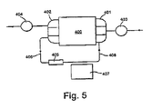
- FIG. 4 there is illustrated schematically a second EGR system.
- the second system for re-circulating exhaust gas from an internal combustion engine 400 having an inlet manifold 401 and an outlet manifold 402, an inlet air compressor 403 and a turbo 404 operating of the exhaust gas and comprises a first EGR cooler 405, an inlet of which is supplied with exhaust gas from the exhaust manifold 402 of the internal combustion engine via an exhaust feed pipe 806, the first EGR cooler receiving high temperature exhaust gas at a temperature in the range 1000 °C - 1100 °C; and a second EGR cooler 407 which receives relatively lower temperature exhaust gas typically at a maximum inlet temperature of around 650 °C, and which cools the gas down to a temperature around 150 °0.
- the cooled exhaust gas being fed through the outlet of the second EGR cooler directly into the inlet manifold 401.
- the second EGR cooler 407 is bypassed, but the first EGR cooler 406 remains in the EGR circuit.
- a temperature at the inlet of the first EGR cooler 406 may be of the order of 400 °C, and gradually rises as the engine warms up, towards a maximum temperature In the range 1000 °C - 1100 °C.
- the second EGR cooler 407 can be bypassed, thereby enabling the engine to heat up to its optimum running temperature more quickly, improving efficiency of the engine.
- the second EGR cooler 407 is switched Into circuit via a valve mechanism to provide further cooling of the exhaust gas before it is fed back into the inlet manifold 401.
- corrugations have been shown for the inner and outer tubular members of the pre-cooler device, the corrugations could be made helical as an alternative embodiment.
- the corrugations extend in either case around a circumference of the inner tubular member, and similarly for the outer tubular member.
- a high gas inlet temperature cooler as described herein may be designed to function with relatively high inlet gas temperatures (up to 1100 °C) and be able to withstand the associated thermal shock loading by using a single gas tube to form the gas conduit.
- the gas conduit may be substantially concentric within an outer cooler conduit, and an annular space between said gas tube and said outer cool tube may form a cavity for a coolant fluid.
- the cooler may avoid having any bulkhead interfacing between the gas conduit and any other component within the cooler.
- a high gas inlet temperature cooler may be used to cool an EGR valve, thus enabling the EGR valve to be located after the high gas inlet temperature cooler and therefore upstream of a relatively lower temperature gas cooler, operating typically at a maximum temperature of around 700 °C.
- the relatively higher gas inlet temperature cooler may be used to cool an exhaust gas re-circulation valve, which enables a lower temperature cooler to be located after the EGR valve.
- the relatively high gas inlet temperature cooler may have a gas inlet interface joint between a gas conduit and the rest of the cooler, which is substantially cooled by the cooler coolant.
- the EGR system may be used for "high pressure" exhaust gas recirculation, i.e. taking gas from pre turbo In the gas flow through an internal combustion engine.
- the EGR system may also be used for "low pressure" exhaust gas recirculation, i.e. taking exhaust gases after passing through a turbo.
- the lower gas inlet temperature cooler may have a bypass valve-such-that gas can bypass the cooler without being significantly cooled.
- the whole of the EGR system may not be bypassed as this would cause the gas inlet to the Induction side to be too hot.
- the lower gas inlet temperature cooler may have an internal gas conduit which is flexible along its axis and have either annular or helical corrugations along its walls.
- the corrugations may be present substantially all the way along the internal gas conduit, or In a restricted section of the gas conduit.
- An outer casing of the lower temperature gas cooler may have annular or helical corrugations to allow flexibility along the length of the casing.
- the corrugations may be present along substantially the entire outer cooler conduit, or may be restricted to a section of its length.
- the embodiments disclosed above may provide an EGR system capable of cooling re-circulated exhaust gas from a maximum temperature of around 1100 °C at a gas inlet to the system, down to a first stage of cooling at a maximum temperature of around 700 °C within a specially designed section which is robust against thermal shock, thermal loading and thermal growth.
- the gas may then be further cooled down from a maximum temperature of around 700 °C within a second cooling section which has a thermal effectiveness of at least 90%, and preferably at least 95%.
- the whole system may be fully integrated, without the use of additional fasteners or connectors between the tubes and sections, to form a unitary welded, brazed or soldered construction.
Landscapes
- Engineering & Computer Science (AREA)
- Physics & Mathematics (AREA)
- Mechanical Engineering (AREA)
- General Engineering & Computer Science (AREA)
- Thermal Sciences (AREA)
- Geometry (AREA)
- Chemical & Material Sciences (AREA)
- Combustion & Propulsion (AREA)
- Exhaust-Gas Circulating Devices (AREA)
- Heat-Exchange Devices With Radiators And Conduit Assemblies (AREA)
- Exhaust Gas After Treatment (AREA)
Abstract
Description
- The present invention relates to gas cooling devices, and particularly although not exclusively to exhaust gas re-circulation coolers for use in automotive applications.
- There are many applications In which it is desirable to use gas heat exchangers. These include applications where it is desirable to cool down a gas, for example in exhaust gas re-circulation (EGR) coolers.
- Exhaust gas re-circulation cooling is used extensively on diesel engines to aid the reduction of nitrous oxide emissions, To aid overall emissions reduction, the EGR cooling on diesel engines may also be bypassed so that the re-circulated exhaust gas is not subject to additional cooling.
- Under some circumstances heat exchange from the gas may be required, but under other circumstances it may be undesirable. For example in cold engine conditions, it is desirable not to additionally cool the gas so that the engine can heat up more quickly. Under hot engine conditions, it may be desirable to cool the gas.
- Exhaust gas re-circulation and the cooling of re-circulating exhaust gases can also be applied in gasoline (petrol) engines. This is of particular use when downsizing a gasoline engine and utilising turbo changing. Cooled exhaust gas re-circulation can help to significantly improve emissions whilst also reducing fuel consumption. A technical challenge of gasoline exhaust gas re-circulation cooling is that the exhaust gas at the inlet to the exhaust gas re-circutation system is much hotter than in the comparable situation with diesel engines. For example, the temperature of re-circulated exhaust gas in a gasoline engine can be up to 1100 °C, but more typically up to around 1000 °C, compared to the equivalent situation in a diesel engine, where the gas temperature at the Inlet to the EGR system is typically of the order of up to 650 °C.
- A common failure mode of diesel exhaust gas re-circulation coolers is that thermal loading causes high stress at the gas inlet interface.
- Referring to
figure 1 herein, there is illustrated schematically in cut away view the inlet of a known exhaust gas re-circulation cooling device. The device comprises an outer casing 1 having a bulkhead 2 which extends across a width of the outer casing, the bulkhead contains a plurality ofgas conduits 3. - When gas flows the gas conduits expand due to their increased temperature from the gas, the outer casing 1 also expands but at a slower rate and has a thermal expansion which is less than the thermal expansion of the gas conduits, resulting in high stresses in the bulkhead and the gas conduits, for example as shown at position A in
figure 1 . The result can include failure of the bulkheads, failure of the joints between the conduit tubes and the bulkhead, failure of tube to tube joints, and collapse of gas tubes. - A typical failure of a tube to bulkhead joint may comprise a crack through the tubular conduit wall, at the position of the weld/braze between the tubular conduit wall and the bulkhead, resulting in mixture of coolant with the exhaust gas re-circulation path.
- For diesel engines, other common problems with exhaust gas re-circulation systems include:
- ● Where the cooled gas inlet temperature is too high, this causes damage to components on the normally cool induction side of the engine.
- ● Exhaust gas re-circulation valves tend to stick due to being at the cold side, which causes "excessive wet" soot fouling on the valve.
- ● The exhaust gas re-circulation valve control system gets too hot
-
EP1,770,250 discloses an exhaust gas cooler having inner and outer corrugated tubes forming a cavity there between in which liquid coolant flows to cool a gas flow through the inner tube. The problem addressed inEP1,770,250 is to replace prior art coolers for diesel engines, having a construction of a plurality of inner tubes and an outer casing, with a simpler structure. The solution presented inEP 1.770.250 is a concentric tube arrangement with a plurality of spacers to keep the tubes apart. - In the device of
EP 1,770,250 the inner tube has a frusto - conical section joining the inner tube to the outer tube at the inlet end, The inlet ends of the inner and outer tubes do not coincide, and the Inlet of the outer tube extends beyond and upstream in the gas flow compared to the inlet end of the inner tube. The outer tube is not in contact with coolant up to the extremity of its inlet end, and therefore heats up due to the high temperatures of the inlet gas.EP1,770,250 does not address the problem of reliability of an exhaust gas cooler used for the hotter exhaust gases which occur in a gasoline engine exhaust system. - Specific embodiments herein aim to provide an exhaust gas re-circulation system which is capable of being robust against the thermal loadings caused by high inlet gas temperatures, whilst giving improve heat exchange.
- According to a first aspect there is provided an exhaust gas cooling device comprising:
- an inner tubular member (501) having an inlet end and an outlet end, said inner tubular member forming a gas passage; and
- an outer tubular member (500), surrounding an outer portion of said inner tubular member and forming a cavity there between for containing a liquid coolant,
- wherein said inner tubular member (501) comprises a plurality of corrugations (504) for absorbing thermal expansion and/or contraction of said inner member; and
- wherein said outer tubular member (500) comprises a plurality of corrugations (505) for absorbing thermal expansion and/or contraction of said outer member;
- Other aspects are as recited in the claims herein.
- For a better understanding of the invention and to show how the same may be carried into effect, there will now be described by way of example only, specific embodiments, methods and processes according to the present invention with reference to the accompanying drawings In which:
-
Figure 1 illustrates schematically a known exhaust gas cooler device having a plurality of gas conduits arranged between a pair of bulkheads within an external casing: -
Figure 2 illustrates schematically an exhaust gas re-circulation cooler according to a specific implementation. -
Figure 3 illustrates schematically a first exhaust gas re-circulation system according to a second specific embodiment; -
Figure 4 illustrates schematically a second exhaust gas re-circulation system according to a further specific embodiment; and -
Figure 5 illustrates schematically the second exhaust gas re-circulation system in a second mode of operation. - There wil now be described by way of example a specific mode contemplated by the inventors. In the following description numerous specific details are sat forth in order to provide a thorough understanding. It will be apparent however, to one skilled in the art, that the present invention may be practiced without limitation to these specific details. In other instances, well known methods and structures have not been described in detail so as not to unnecessarily obscure the description.
- Referring to
figure 2 herein, there is illustrated schematically a high temperature exhaust gas cooler according to a specific embodiment. The exhaustgas re-circulation cooler 200 comprises a metallic inner tubular substantiallycylindrical member 201, and a co-axially aligned substantially cylindrical tubular outer member 202, surrounding the inner member and spaced apart therefrom, providing a sealed cavity between the inner and outer members, which provides a fluid fillable jacket around a central passage 503 through the inner tubular member, for cooling hot exhaust gases which pass through the cooling device. - The inner
tubular member 201 comprises a plurality of annular orhelical corrugations 203. - The primary purpose of the corrugations is for absorbing expansion and contraction stresses in a direction axially of the inner tubular member, thereby enabling the inner tubular member to operate with an elevated temperature gradient along the cooler, between an inlet temperature of 1100°C maximum and an outlet temperature of around 700 °C maximum. Similarly, the outer tubular member 202 is also provided with a plurality of annular or helical corrugations 505 for a similar purpose, that is, to absorb axial expansion and contraction and axial stresses and strains between the two ends of the cooler, and to enable the cooler to operate over a temperature gradient between a maximum of around 1100 °C at one end and a maximum temperature of around 700 °C at the other end. The outer tubular member 202 is provided with a fluid inlet tube 506, and a
fluid outlet tube 207 for entry and outlet of a liquid coolant which fills the cavity between the inner and outer tubular members. - The corrugations also have the effect of increasing the surface area in contact with the hot exhaust gases flowing through the inner tube, and coating local turbulence at the interface between the gas and the tube wall, thereby increasing the heat transfer rate between the gas and the tubular wall.
- The inner and outer tubular members are joined at the inlet end by a first annular plate member 508 extending between the substantially parallel cylindrical walls of the respective inner and outer
tubular members 202, 205. Similarly, at the outlet end of the cooler, a second annular plate member 209 joins the other ends of the inner and outer tubular members. Said annular plates may be formed as part of the gas conduit. Alternatively, said annular platens may be formed as part of the coolant conduit. - In the embodiments shown, there are no internal bulkheads in the gas flow path, and the ends of the cooler are liquid cooled. The interface components to this embodiment would have a gas path diameter not grater than the diameter of the gas conduit ends, such that said annular plates are not in the gas flow path. The inner tubular member and the outer tubular member do not contact each other, except at their respective corresponding ends, where they are connected together
- Referring to
figure 3 herein, there is illustrated schematically an arrangement of an engine and a first exhaust gas re-circulation bypass system according to a second specific embodiment herein. - An
internal combustion engine 300 comprises aninlet manifold 301 for drawing air Into the combustion chambers of the engine, and anoutlet manifold 302 for channeling exhaust gases out of the engine. Air being input Into the inlet manifold may be compressed by acompressor 303. Additionally and optionally, aturbo 304 may be fitted after the exhaust manifold to anexhaust channel 305 of the engine. - To improve combustion efficiency and reduce harmful emissions, the engine may be fitted with an exhaust gas re-circulation EGR system. The EGR system comprises a first exhaust gas cooler 306 through which exhaust gases flow, and a
second exhaust cooler 307, the first and second exhaust coolers being connected in series. - A high pressure exhaust gas re-circulation circuit takes high pressure exhaust gas from the
outlet manifold 302, through afeed pipe 308 to the inlet of thefirst EGR cooler 306, and from an outlet of thesecond EGR cooler 307, directly to theinlet manifold 301 via asecond feed pipe 309. High pressure recirculated exhaust gas is cooled, but does not pass through thecompressor 303 or theturbo 304. - An alternative low pressure EGR system takes the exhaust gas downstream of the
turbo 304 and feeds It via athird feed pipe 310 to the inlet of thefirst EGR cooler 306, through thefirst EGR cooler 306 via a connectingpipe 311 to the inlet of thesecond EGR cooler 307, and from the outlet of thesecond EGR cooler 307, to an air channel inlet upstream ofcompressor 303, via afourth feed pipe 312. - The purpose of the
first EGR cooler 306 is to cool the high temperature exhaust gases from a temperature of 1000 to 1100 °C down to a temperature of around 650 °C prior to entry to thesecond EGR cooler 307. Gas is entering the second EGR cooler 307 at an inlet temperature of around 650 °C may exit the second EGR cooler at a reduced temperature of around 150 °C. - By using a single gas conduit first EGR cooler 306 in the hot exhaust gas, before a multi gas
conduit EGR cooler 307, the first EGR cooler can be used to cool the exhaust gas from a relatively higher temperature having a maximum temperature in the range 1000 °C - 1100 °C. to a relatively lower temperature of the order of 650 °C. Since the exhaust gas has been cooled prior to entry on the multi gasconduit EGR cooler 307. the multi gas conduit EGR cooler will not suffer cracking of the gas conduits where they connect to the bulkhead inside the EGR cooler. - It will be appreciated by the person skilled in the art that variations on the high pressure EGR and the low pressure EGR may be provided.
- In a first variation, the exhaust gas is taken at a relatively lower pressure, after the
turbo 304 and via thesecond feed pipe 310, through the first and second EGR coolers, and through thesecond feed pipe 309 directly into the inlet without going through the compressor. In a second variation, high pressure exhaust gas may be taken by thefirst feed pipe 308 through the first andsecond EGR coolers compressor 303 viafourth feed pipe 312. - The exhaust gas re-circulation system may operate to cool gas from a maximum inlet temperature of 1100 °C, to a maximum temperature of around 300 °C at the outlet of the first cooler device. This may not be a highly effective cooler. The first cooler device may be robust so as to withstand thermal shock, thermal loading and thermal growth as experienced in automotive applications. The gas may be cooled from an inlet temperature of the second cooler device of around 700 °C to around 150 °C. with a thermal effectiveness of at least 80%. Preferably, the thermal effectiveness of the second cooler section is in the range 90% to 95%.
- The exhaust gas re-circulation system may be fully integrated as a set of connecting pipes and cooler devices being of welded, brazed or soldered construction, without the need for being joined by fasteners, external damps or other additional mechanical fixings.
- Referring to
figure 4 herein, there is illustrated schematically a second EGR system. - The second system for re-circulating exhaust gas from an
internal combustion engine 400 having aninlet manifold 401 and anoutlet manifold 402, aninlet air compressor 403 and aturbo 404 operating of the exhaust gas, and comprises afirst EGR cooler 405, an inlet of which is supplied with exhaust gas from theexhaust manifold 402 of the internal combustion engine via an exhaust feed pipe 806, the first EGR cooler receiving high temperature exhaust gas at a temperature in the range 1000 °C - 1100 °C; and a second EGR cooler 407 which receives relatively lower temperature exhaust gas typically at a maximum inlet temperature of around 650 °C, and which cools the gas down to a temperature around 150 °0. The cooled exhaust gas being fed through the outlet of the second EGR cooler directly into theinlet manifold 401. - Referring to
figure 5 herein, the system offig 4 is shown during a warm up phase of the engine, when the engine has just been started and is raising towards its normal operating temperature. - In these circumstances, the
second EGR cooler 407 is bypassed, but the first EGR cooler 406 remains in the EGR circuit. Under warm up conditions, a temperature at the inlet of thefirst EGR cooler 406 may be of the order of 400 °C, and gradually rises as the engine warms up, towards a maximum temperature In the range 1000 °C - 1100 °C. As long as the exhaust gas at the outlet of the EGR system remains at a maximum temperature in the range 150 °C or less, then the second EGR cooler 407 can be bypassed, thereby enabling the engine to heat up to its optimum running temperature more quickly, improving efficiency of the engine. - However, once the engine gets up to operating temperature, and the temperature of the exhaust gas at the outlet of the first EGR cooler rises above around 150 °C, then the
second EGR cooler 407 is switched Into circuit via a valve mechanism to provide further cooling of the exhaust gas before it is fed back into theinlet manifold 401. - It will be appreciated by those skilled in the art that although annular corrugations have been shown for the inner and outer tubular members of the pre-cooler device, the corrugations could be made helical as an alternative embodiment. The corrugations extend in either case around a circumference of the inner tubular member, and similarly for the outer tubular member.
- A high gas inlet temperature cooler as described herein may be designed to function with relatively high inlet gas temperatures (up to 1100 °C) and be able to withstand the associated thermal shock loading by using a single gas tube to form the gas conduit. The gas conduit may be substantially concentric within an outer cooler conduit, and an annular space between said gas tube and said outer cool tube may form a cavity for a coolant fluid. The cooler may avoid having any bulkhead interfacing between the gas conduit and any other component within the cooler.
- In the exhaust gas re-circulation systems described herein, a high gas inlet temperature cooler may be used to cool an EGR valve, thus enabling the EGR valve to be located after the high gas inlet temperature cooler and therefore upstream of a relatively lower temperature gas cooler, operating typically at a maximum temperature of around 700 °C.
- The relatively higher gas inlet temperature cooler may be used to cool an exhaust gas re-circulation valve, which enables a lower temperature cooler to be located after the EGR valve.
- The relatively high gas inlet temperature cooler may have a gas inlet interface joint between a gas conduit and the rest of the cooler, which is substantially cooled by the cooler coolant.
- The EGR system may be used for "high pressure" exhaust gas recirculation, i.e. taking gas from pre turbo In the gas flow through an internal combustion engine.
- The EGR system may also be used for "low pressure" exhaust gas recirculation, i.e. taking exhaust gases after passing through a turbo.
- The lower gas inlet temperature cooler may have a bypass valve-such-that gas can bypass the cooler without being significantly cooled. The whole of the EGR system may not be bypassed as this would cause the gas inlet to the Induction side to be too hot.
- The lower gas inlet temperature cooler, may have an internal gas conduit which is flexible along its axis and have either annular or helical corrugations along its walls. The corrugations may be present substantially all the way along the internal gas conduit, or In a restricted section of the gas conduit.
- An outer casing of the lower temperature gas cooler may have annular or helical corrugations to allow flexibility along the length of the casing. The corrugations may be present along substantially the entire outer cooler conduit, or may be restricted to a section of its length.
- The embodiments disclosed above may provide an EGR system capable of cooling re-circulated exhaust gas from a maximum temperature of around 1100 °C at a gas inlet to the system, down to a first stage of cooling at a maximum temperature of around 700 °C within a specially designed section which is robust against thermal shock, thermal loading and thermal growth. The gas may then be further cooled down from a maximum temperature of around 700 °C within a second cooling section which has a thermal effectiveness of at least 90%, and preferably at least 95%.
- In the EGR system embodiment shown above, the whole system may be fully integrated, without the use of additional fasteners or connectors between the tubes and sections, to form a unitary welded, brazed or soldered construction.
said inner and outer tubular members do not contact each other at said inlet end except where they are connected together by said member (508) thereby allowing said inlet end to be liquid cooled.
Claims (22)
- An exhaust gas cooling device comprising:an inner tubular member (201) having an inlet end and an outlet end, said inner tubular member forming a gas passage; andan outer tubular member (200), surrounding an outer portion of said inner tubular member and forming a cavity there between for containing a liquid coolant,wherein said inner tubular member (201) comprises a plurality of corrugations (504) for absorbing thermal expansion and/or contraction of said inner member; andwherein said outer tubular member (200) comprises a plurality of corrugations (205) for absorbing thermal expansion and/or contraction of said outer member;characterised in that said inner and outer tubular members are joined at the inlet end by a member (208) extending between the walls of the respective inner and outer tubular members; and
at said inlet end, said inner and outer tubular members do not contact each other except where they are connected together by said member (208) thereby allowing said inlet end to be liquid cooled. - The cooling device as claimed in claim 1, wherein said cavity extends substantially a full length along said inner (201) and outer (200) tubular members, such that first and second end extremities of said cooling device are cooled in use by a coolant fluid flowing through said cavity formed between said inner and outer tubular members.
- The cooling device as claimed in claim 1 or 2, wherein the inner (201) and outer (200) tubular members are arranged so as not to contact each other, other than at first ends of the inner and outer members, and at second ends of the inner and outer tubular members.
- The cooling device as claimed in any one of the preceding claims, wherein said cooling device has no bulkhead component to join the inner tubular member (201) to the outer tubular member (202).
- The cooling device as claimed in any one of the preceding claims, wherein said inner tubular member comprises a plurality of annular or helical corrugations (203).
- The cooling device as claimed in claim 5, wherein said corrugations (203) on said inner tubular member extend over a length of between 10% and 85% of an overall length of said inner tubular member.
- The cooling device as claimed in any one of the preceding claims, wherein said outer tubular member has a set of corrugations (205) which extend over a proportion of between 10% and 100% of the length of the outer tubular member.
- The cooling device as claimed in any one of the preceding claims, wherein a main central axis of an inlet end of said inner tubular member lies at an angle with respect to a main central axis of an outlet of said inner tubular member, and said inner and outer members are bent, such that the cooling device forms a curved or bent component.
- The cooling device as claimed in any one of the preceding claims, capable of operating in a temperature range of -60°C to 1100°C.
- The cooling device as claimed in any one of the preceding claims, wherein said outer tubular member comprises a plurality of annular or helical corrugations (205).
- The cooling device as claimed in any one of the preceding claims, wherein said inner tubular member comprises;
a first type of corrugation having a peak to peak spacing between adjacent corrugations in a direction along the main length of the inner tubular member of a distance corresponding to 16% to 20% of the distance across the tubular member. - The cooling device as claimed in any one of the preceding claims, comprising a first type of corrugation, having a peak to trough distance in the radial direction in the range of 6% to 8% of the internal radial distance of the inner tubular member.
- The cooling device as claimed in any one of the preceding claims, having a second type of corrugation comprising a substantial toroidal surface.
- The cooling device as claimed in claim 13, wherein said corrugations of said second type have a peak to trough radial distance in the range of 10% to 14% of a maximum radius of the inner tubular member.
- The cooling device as claimed in any one of the preceding claims, comprising at least one elongate indent, said elongate indent extending along a main axial direction of said inner tubular member.
- The cooling device as claimed in any one of the preceding claims, comprising at least one elongate indent, said elongate indent extending along a main axial length of said inner tubular member;
said indent comprising a wall portion which extends in to a main inner passage of said inner tubular member to a distance in the range 15% - 90% of a distance across said inner tubular member. - The cooling device as claimed in claim 16, comprising a plurality of said elongate indents, said plurality of indents opposing each other, such that an internal cross sectional profile of an internal passage of inner tubular member forms a substantially butterfly or double mushroom shape.
- The cooling device as claimed in claim 16 or 17, wherein each said elongate indent has super imposed a plurality of corrugations extending circumferentially around said inner tubular member.
- The cooling device as claimed in any one of the preceding claims, comprising a second tubular end piece in to which connects a second end of said inner tubular member and a second end of said outer tubular member, such that said inner and outer tubular members are spaced apart from each other with the cavity there between, and do not touch each other.
- The cooling device as claimed in any one of the preceding claims, wherein said inner tubular member and said outer tubular member are constructed so as not to contact each other except at said inlet end and said outlet end.
- The cooling device as claimed in any one of the preceding claims, wherein said first cooling device is capable of cooling said exhaust gas from a maximum inlet temperature of 1100°C, to a maximum outlet temperature of 700°C.
- An exhaust gas re-circulation system for an internal combustion engine, said system comprising:a first cooling device as claimed in any one of claims 1 to 21, configured for receiving exhaust gas from said internal combustion engine; anda second cooling device connected in series with said first cooling device and arranged for receiving cooled exhaust gas from an outlet of said first cooler device, an outlet of said second cooling device being connected to an inlet of said internal combustion engine.
Priority Applications (1)
| Application Number | Priority Date | Filing Date | Title |
|---|---|---|---|
| EP12173479.2A EP2570646B1 (en) | 2007-08-15 | 2008-08-11 | High gas inlet temperature EGR system |
Applications Claiming Priority (2)
| Application Number | Priority Date | Filing Date | Title |
|---|---|---|---|
| GB0715891A GB2451862A (en) | 2007-08-15 | 2007-08-15 | High gas inlet temperature EGR system |
| PCT/GB2008/002704 WO2009022113A1 (en) | 2007-08-15 | 2008-08-11 | High gas inlet temperature egr system |
Related Child Applications (2)
| Application Number | Title | Priority Date | Filing Date |
|---|---|---|---|
| EP12173479.2A Division EP2570646B1 (en) | 2007-08-15 | 2008-08-11 | High gas inlet temperature EGR system |
| EP12173479.2 Division-Into | 2012-06-25 |
Publications (2)
| Publication Number | Publication Date |
|---|---|
| EP2215346A1 EP2215346A1 (en) | 2010-08-11 |
| EP2215346B1 true EP2215346B1 (en) | 2012-11-21 |
Family
ID=38566411
Family Applications (2)
| Application Number | Title | Priority Date | Filing Date |
|---|---|---|---|
| EP12173479.2A Active EP2570646B1 (en) | 2007-08-15 | 2008-08-11 | High gas inlet temperature EGR system |
| EP08788275A Active EP2215346B1 (en) | 2007-08-15 | 2008-08-11 | High gas inlet temperature egr system |
Family Applications Before (1)
| Application Number | Title | Priority Date | Filing Date |
|---|---|---|---|
| EP12173479.2A Active EP2570646B1 (en) | 2007-08-15 | 2008-08-11 | High gas inlet temperature EGR system |
Country Status (3)
| Country | Link |
|---|---|
| EP (2) | EP2570646B1 (en) |
| GB (1) | GB2451862A (en) |
| WO (1) | WO2009022113A1 (en) |
Families Citing this family (19)
| Publication number | Priority date | Publication date | Assignee | Title |
|---|---|---|---|---|
| DE102009040560A1 (en) * | 2009-09-08 | 2011-03-10 | Krones Ag | Tubular Heat Exchangers |
| DE102009047620C5 (en) | 2009-12-08 | 2023-01-19 | Hanon Systems | Heat exchanger with tube bundle |
| DE102010006370B4 (en) * | 2010-01-29 | 2021-08-19 | Wallstein Ingenieur-Gesellschaft Mbh | Heat exchanger |
| DE102010033718B4 (en) | 2010-08-07 | 2015-04-30 | Audi Ag | Car with an internal combustion engine |
| DE102010036946A1 (en) | 2010-08-11 | 2012-02-16 | Ford Global Technologies, Llc. | High pressure exhaust gas recirculation system with heat recovery |
| DE102010045259A1 (en) | 2010-09-14 | 2012-03-15 | Pierburg Gmbh | cooling arrangement |
| IT1406069B1 (en) * | 2010-09-16 | 2014-02-06 | Dytech Dynamic Fluid Tech Spa | HEAT EXCHANGER PARTICULARLY FOR A AIR CONDITIONING SYSTEM FOR A VEHICLE |
| WO2013019761A1 (en) * | 2011-07-29 | 2013-02-07 | Claudio Filippone | Waste heat recovery and conversion system and related methods |
| ITCO20110033A1 (en) * | 2011-08-25 | 2013-02-26 | Nuovo Pignone Spa | INTEGRATED HEAT EXCHANGER WITH PRESSURE COMPENSATION AND METHOD |
| BE1020321A3 (en) * | 2011-10-19 | 2013-08-06 | Atlas Copco Airpower Nv | TUBE HEAT EXCHANGER AND COMPRESSOR UNIT EQUIPPED. |
| CN102734004A (en) | 2012-05-15 | 2012-10-17 | 浙江银轮机械股份有限公司 | Waste gas inlet end structure of EGR (Exhaust Gas Recirculation) cooler |
| CN104196652B (en) * | 2014-08-13 | 2017-06-27 | 潍柴动力股份有限公司 | The control method and control device of a kind of egr system and its cold rear intake air temperature |
| JP6362515B2 (en) * | 2014-11-11 | 2018-07-25 | 三恵技研工業株式会社 | EGR cooler and manufacturing method thereof |
| DE102015220742A1 (en) * | 2015-10-23 | 2017-04-27 | Arvos Gmbh | Industrierußherstellungsanlage |
| EP3163243B1 (en) * | 2015-10-28 | 2019-08-14 | Borgwarner Emissions Systems Spain, S.L.U. | Evaporator |
| JP2017198392A (en) * | 2016-04-27 | 2017-11-02 | 株式会社ヴァレオジャパン | Double tube |
| WO2017034043A1 (en) * | 2016-09-26 | 2017-03-02 | 株式会社小松製作所 | Egr device and dump truck provided with same |
| CN113423235B (en) * | 2021-05-11 | 2022-04-22 | 西安交通大学 | Cooling system for airborne electronic equipment |
| CN121557014A (en) * | 2026-01-23 | 2026-02-24 | 浙江邦得利环保科技股份有限公司 | Front-end precooler of EGR cooler |
Family Cites Families (15)
| Publication number | Priority date | Publication date | Assignee | Title |
|---|---|---|---|---|
| US4203312A (en) * | 1977-09-29 | 1980-05-20 | Spiral Tubing Corporation | Corrugated tubing with variable depth corrugations and method of making the same |
| DE3209240C2 (en) * | 1982-03-13 | 1985-09-26 | Dieter Steinegg-Appenzell Steeb | Cross-flow plate heat exchanger |
| DE4414429C1 (en) * | 1994-04-26 | 1995-06-01 | Mtu Friedrichshafen Gmbh | Cooling of hot diesel exhaust gas |
| DE19731129A1 (en) * | 1997-07-19 | 1999-01-21 | Volkswagen Ag | Single cylinder throttling including exhaust gas recirculation |
| ES2163317T3 (en) * | 1999-10-26 | 2002-01-16 | Senior Flexonics Automotive Lt | REFRIGERATOR BY RECIRCULATION OF EXHAUST GASES. |
| JP2002130060A (en) * | 2000-10-24 | 2002-05-09 | Katayama Kogyo Co Ltd | EGR gas cooling device |
| DE10232515A1 (en) * | 2002-07-18 | 2004-04-08 | Daimlerchrysler Ag | Exhaust gas recirculation of an internal combustion engine |
| JP4323333B2 (en) * | 2004-01-19 | 2009-09-02 | 株式会社マーレ フィルターシステムズ | Exhaust gas recirculation device for internal combustion engine |
| JP2005220747A (en) * | 2004-02-03 | 2005-08-18 | Usui Kokusai Sangyo Kaisha Ltd | Egr gas cooling mechanism |
| SE526821C2 (en) * | 2004-03-31 | 2005-11-08 | Scania Cv Ab | Arrangements for the recirculation of exhaust gases of a supercharged internal combustion engine |
| GB2417067B (en) * | 2004-08-12 | 2006-09-06 | Senior Uk Ltd | Improved gas heat exchanger |
| JP3928642B2 (en) * | 2005-01-18 | 2007-06-13 | いすゞ自動車株式会社 | EGR device |
| DE102005029322A1 (en) * | 2005-06-24 | 2006-12-28 | Behr Gmbh & Co. Kg | Device for recycling and cooling exhaust gas for an internal combustion engine |
| SE529101C2 (en) * | 2005-09-20 | 2007-05-02 | Scania Cv Ab | Cooling arrangement for the recirculation of gases of a supercharged internal combustion engine |
| DE102005046536A1 (en) * | 2005-09-28 | 2007-03-29 | Witzenmann Gmbh | Heat exchanger for exhaust gas recirculation line, has hose line extending concentrically to casing line, and spacing units arranged in outer flow area between casing line and hose line, where hose line has annular wave-shaped corrugation |
-
2007
- 2007-08-15 GB GB0715891A patent/GB2451862A/en not_active Withdrawn
-
2008
- 2008-08-11 EP EP12173479.2A patent/EP2570646B1/en active Active
- 2008-08-11 EP EP08788275A patent/EP2215346B1/en active Active
- 2008-08-11 WO PCT/GB2008/002704 patent/WO2009022113A1/en not_active Ceased
Also Published As
| Publication number | Publication date |
|---|---|
| WO2009022113A1 (en) | 2009-02-19 |
| GB2451862A (en) | 2009-02-18 |
| EP2215346A1 (en) | 2010-08-11 |
| GB0715891D0 (en) | 2007-09-26 |
| EP2570646A1 (en) | 2013-03-20 |
| EP2570646B1 (en) | 2016-05-11 |
Similar Documents
| Publication | Publication Date | Title |
|---|---|---|
| EP2570646B1 (en) | High gas inlet temperature EGR system | |
| EP2344797B1 (en) | Multi-tubular fluid transfer conduit | |
| JP6397411B2 (en) | Improved exhaust gas recirculation device and method for forming the same | |
| JP4341224B2 (en) | Fuel injector fuel conduit with multi-laminate fuel strip | |
| US7255096B2 (en) | Gas heat exchanger | |
| JP6114379B2 (en) | Spiral tube EGR cooler | |
| US9581107B2 (en) | Exhaust gas heat exchanging device | |
| EP3133363B1 (en) | Finned coaxial cooler | |
| EP3543636B1 (en) | Finned coaxial cooler | |
| CN105829694A (en) | Fuel system and components | |
| US8656709B2 (en) | Dual-layer to flange welded joint | |
| JP4345470B2 (en) | Engine EGR cooler | |
| US9403204B2 (en) | Heat exchanger assembly and method | |
| JP4844600B2 (en) | Exhaust heat recovery unit | |
| JP2005273512A (en) | Engine EGR cooler | |
| EP2681480B1 (en) | Pipe unit in a conduit for a gaseous medium | |
| JP2005214586A (en) | Exhaust gas cooling heat exchanger | |
| CN217463743U (en) | High-temperature-resistant EGR (exhaust gas Recirculation) connecting pipe with composite layer flow guide pipe structure | |
| WO2013184135A1 (en) | Egr cooler header casting | |
| WO2019031090A1 (en) | Heat exchanger | |
| US20210017898A1 (en) | Floating core heat exchanger | |
| CN117432511A (en) | A bidirectional flow combined regulation structure based on flow separation | |
| GB2571637A (en) | Finned coaxial cooler |
Legal Events
| Date | Code | Title | Description |
|---|---|---|---|
| PUAI | Public reference made under article 153(3) epc to a published international application that has entered the european phase |
Free format text: ORIGINAL CODE: 0009012 |
|
| 17P | Request for examination filed |
Effective date: 20100203 |
|
| AK | Designated contracting states |
Kind code of ref document: A1 Designated state(s): AT BE BG CH CY CZ DE DK EE ES FI FR GB GR HR HU IE IS IT LI LT LU LV MC MT NL NO PL PT RO SE SI SK TR |
|
| AX | Request for extension of the european patent |
Extension state: AL BA MK RS |
|
| 17Q | First examination report despatched |
Effective date: 20100823 |
|
| DAX | Request for extension of the european patent (deleted) | ||
| GRAP | Despatch of communication of intention to grant a patent |
Free format text: ORIGINAL CODE: EPIDOSNIGR1 |
|
| GRAS | Grant fee paid |
Free format text: ORIGINAL CODE: EPIDOSNIGR3 |
|
| GRAP | Despatch of communication of intention to grant a patent |
Free format text: ORIGINAL CODE: EPIDOSNIGR1 |
|
| GRAA | (expected) grant |
Free format text: ORIGINAL CODE: 0009210 |
|
| AK | Designated contracting states |
Kind code of ref document: B1 Designated state(s): AT BE BG CH CY CZ DE DK EE ES FI FR GB GR HR HU IE IS IT LI LT LU LV MC MT NL NO PL PT RO SE SI SK TR |
|
| REG | Reference to a national code |
Ref country code: GB Ref legal event code: FG4D |
|
| RIN1 | Information on inventor provided before grant (corrected) |
Inventor name: PENNY, CHARLES Inventor name: DOWNS, PAUL |
|
| REG | Reference to a national code |
Ref country code: CH Ref legal event code: EP |
|
| REG | Reference to a national code |
Ref country code: AT Ref legal event code: REF Ref document number: 585211 Country of ref document: AT Kind code of ref document: T Effective date: 20121215 |
|
| REG | Reference to a national code |
Ref country code: IE Ref legal event code: FG4D |
|
| REG | Reference to a national code |
Ref country code: DE Ref legal event code: R096 Ref document number: 602008020293 Country of ref document: DE Effective date: 20130117 |
|
| REG | Reference to a national code |
Ref country code: NL Ref legal event code: VDEP Effective date: 20121121 |
|
| REG | Reference to a national code |
Ref country code: AT Ref legal event code: MK05 Ref document number: 585211 Country of ref document: AT Kind code of ref document: T Effective date: 20121121 |
|
| REG | Reference to a national code |
Ref country code: LT Ref legal event code: MG4D |
|
| PG25 | Lapsed in a contracting state [announced via postgrant information from national office to epo] |
Ref country code: LT Free format text: LAPSE BECAUSE OF FAILURE TO SUBMIT A TRANSLATION OF THE DESCRIPTION OR TO PAY THE FEE WITHIN THE PRESCRIBED TIME-LIMIT Effective date: 20121121 Ref country code: SE Free format text: LAPSE BECAUSE OF FAILURE TO SUBMIT A TRANSLATION OF THE DESCRIPTION OR TO PAY THE FEE WITHIN THE PRESCRIBED TIME-LIMIT Effective date: 20121121 Ref country code: HR Free format text: LAPSE BECAUSE OF FAILURE TO SUBMIT A TRANSLATION OF THE DESCRIPTION OR TO PAY THE FEE WITHIN THE PRESCRIBED TIME-LIMIT Effective date: 20121121 Ref country code: ES Free format text: LAPSE BECAUSE OF FAILURE TO SUBMIT A TRANSLATION OF THE DESCRIPTION OR TO PAY THE FEE WITHIN THE PRESCRIBED TIME-LIMIT Effective date: 20130304 Ref country code: FI Free format text: LAPSE BECAUSE OF FAILURE TO SUBMIT A TRANSLATION OF THE DESCRIPTION OR TO PAY THE FEE WITHIN THE PRESCRIBED TIME-LIMIT Effective date: 20121121 Ref country code: NO Free format text: LAPSE BECAUSE OF FAILURE TO SUBMIT A TRANSLATION OF THE DESCRIPTION OR TO PAY THE FEE WITHIN THE PRESCRIBED TIME-LIMIT Effective date: 20130221 |
|
| PG25 | Lapsed in a contracting state [announced via postgrant information from national office to epo] |
Ref country code: PL Free format text: LAPSE BECAUSE OF FAILURE TO SUBMIT A TRANSLATION OF THE DESCRIPTION OR TO PAY THE FEE WITHIN THE PRESCRIBED TIME-LIMIT Effective date: 20121121 Ref country code: LV Free format text: LAPSE BECAUSE OF FAILURE TO SUBMIT A TRANSLATION OF THE DESCRIPTION OR TO PAY THE FEE WITHIN THE PRESCRIBED TIME-LIMIT Effective date: 20121121 Ref country code: PT Free format text: LAPSE BECAUSE OF FAILURE TO SUBMIT A TRANSLATION OF THE DESCRIPTION OR TO PAY THE FEE WITHIN THE PRESCRIBED TIME-LIMIT Effective date: 20130321 Ref country code: SI Free format text: LAPSE BECAUSE OF FAILURE TO SUBMIT A TRANSLATION OF THE DESCRIPTION OR TO PAY THE FEE WITHIN THE PRESCRIBED TIME-LIMIT Effective date: 20121121 Ref country code: GR Free format text: LAPSE BECAUSE OF FAILURE TO SUBMIT A TRANSLATION OF THE DESCRIPTION OR TO PAY THE FEE WITHIN THE PRESCRIBED TIME-LIMIT Effective date: 20130222 Ref country code: BE Free format text: LAPSE BECAUSE OF FAILURE TO SUBMIT A TRANSLATION OF THE DESCRIPTION OR TO PAY THE FEE WITHIN THE PRESCRIBED TIME-LIMIT Effective date: 20121121 |
|
| PG25 | Lapsed in a contracting state [announced via postgrant information from national office to epo] |
Ref country code: AT Free format text: LAPSE BECAUSE OF FAILURE TO SUBMIT A TRANSLATION OF THE DESCRIPTION OR TO PAY THE FEE WITHIN THE PRESCRIBED TIME-LIMIT Effective date: 20121121 |
|
| PG25 | Lapsed in a contracting state [announced via postgrant information from national office to epo] |
Ref country code: BG Free format text: LAPSE BECAUSE OF FAILURE TO SUBMIT A TRANSLATION OF THE DESCRIPTION OR TO PAY THE FEE WITHIN THE PRESCRIBED TIME-LIMIT Effective date: 20130221 Ref country code: EE Free format text: LAPSE BECAUSE OF FAILURE TO SUBMIT A TRANSLATION OF THE DESCRIPTION OR TO PAY THE FEE WITHIN THE PRESCRIBED TIME-LIMIT Effective date: 20121121 Ref country code: SK Free format text: LAPSE BECAUSE OF FAILURE TO SUBMIT A TRANSLATION OF THE DESCRIPTION OR TO PAY THE FEE WITHIN THE PRESCRIBED TIME-LIMIT Effective date: 20121121 Ref country code: CZ Free format text: LAPSE BECAUSE OF FAILURE TO SUBMIT A TRANSLATION OF THE DESCRIPTION OR TO PAY THE FEE WITHIN THE PRESCRIBED TIME-LIMIT Effective date: 20121121 Ref country code: DK Free format text: LAPSE BECAUSE OF FAILURE TO SUBMIT A TRANSLATION OF THE DESCRIPTION OR TO PAY THE FEE WITHIN THE PRESCRIBED TIME-LIMIT Effective date: 20121121 |
|
| PG25 | Lapsed in a contracting state [announced via postgrant information from national office to epo] |
Ref country code: RO Free format text: LAPSE BECAUSE OF FAILURE TO SUBMIT A TRANSLATION OF THE DESCRIPTION OR TO PAY THE FEE WITHIN THE PRESCRIBED TIME-LIMIT Effective date: 20121121 Ref country code: NL Free format text: LAPSE BECAUSE OF FAILURE TO SUBMIT A TRANSLATION OF THE DESCRIPTION OR TO PAY THE FEE WITHIN THE PRESCRIBED TIME-LIMIT Effective date: 20121121 Ref country code: IT Free format text: LAPSE BECAUSE OF FAILURE TO SUBMIT A TRANSLATION OF THE DESCRIPTION OR TO PAY THE FEE WITHIN THE PRESCRIBED TIME-LIMIT Effective date: 20121121 |
|
| PLBE | No opposition filed within time limit |
Free format text: ORIGINAL CODE: 0009261 |
|
| STAA | Information on the status of an ep patent application or granted ep patent |
Free format text: STATUS: NO OPPOSITION FILED WITHIN TIME LIMIT |
|
| 26N | No opposition filed |
Effective date: 20130822 |
|
| REG | Reference to a national code |
Ref country code: DE Ref legal event code: R097 Ref document number: 602008020293 Country of ref document: DE Effective date: 20130822 |
|
| REG | Reference to a national code |
Ref country code: CH Ref legal event code: PL |
|
| PG25 | Lapsed in a contracting state [announced via postgrant information from national office to epo] |
Ref country code: LI Free format text: LAPSE BECAUSE OF NON-PAYMENT OF DUE FEES Effective date: 20130831 Ref country code: MC Free format text: LAPSE BECAUSE OF FAILURE TO SUBMIT A TRANSLATION OF THE DESCRIPTION OR TO PAY THE FEE WITHIN THE PRESCRIBED TIME-LIMIT Effective date: 20121121 Ref country code: CH Free format text: LAPSE BECAUSE OF NON-PAYMENT OF DUE FEES Effective date: 20130831 |
|
| REG | Reference to a national code |
Ref country code: IE Ref legal event code: MM4A |
|
| REG | Reference to a national code |
Ref country code: FR Ref legal event code: ST Effective date: 20140430 |
|
| PG25 | Lapsed in a contracting state [announced via postgrant information from national office to epo] |
Ref country code: IE Free format text: LAPSE BECAUSE OF NON-PAYMENT OF DUE FEES Effective date: 20130811 |
|
| PG25 | Lapsed in a contracting state [announced via postgrant information from national office to epo] |
Ref country code: FR Free format text: LAPSE BECAUSE OF NON-PAYMENT OF DUE FEES Effective date: 20130902 |
|
| PG25 | Lapsed in a contracting state [announced via postgrant information from national office to epo] |
Ref country code: CY Free format text: LAPSE BECAUSE OF FAILURE TO SUBMIT A TRANSLATION OF THE DESCRIPTION OR TO PAY THE FEE WITHIN THE PRESCRIBED TIME-LIMIT Effective date: 20121121 Ref country code: MT Free format text: LAPSE BECAUSE OF FAILURE TO SUBMIT A TRANSLATION OF THE DESCRIPTION OR TO PAY THE FEE WITHIN THE PRESCRIBED TIME-LIMIT Effective date: 20121121 Ref country code: TR Free format text: LAPSE BECAUSE OF FAILURE TO SUBMIT A TRANSLATION OF THE DESCRIPTION OR TO PAY THE FEE WITHIN THE PRESCRIBED TIME-LIMIT Effective date: 20121121 |
|
| PG25 | Lapsed in a contracting state [announced via postgrant information from national office to epo] |
Ref country code: HU Free format text: LAPSE BECAUSE OF FAILURE TO SUBMIT A TRANSLATION OF THE DESCRIPTION OR TO PAY THE FEE WITHIN THE PRESCRIBED TIME-LIMIT; INVALID AB INITIO Effective date: 20080811 Ref country code: LU Free format text: LAPSE BECAUSE OF NON-PAYMENT OF DUE FEES Effective date: 20130811 |
|
| PG25 | Lapsed in a contracting state [announced via postgrant information from national office to epo] |
Ref country code: IS Free format text: LAPSE BECAUSE OF FAILURE TO SUBMIT A TRANSLATION OF THE DESCRIPTION OR TO PAY THE FEE WITHIN THE PRESCRIBED TIME-LIMIT Effective date: 20121121 |
|
| PGFP | Annual fee paid to national office [announced via postgrant information from national office to epo] |
Ref country code: DE Payment date: 20250812 Year of fee payment: 18 |
|
| PGFP | Annual fee paid to national office [announced via postgrant information from national office to epo] |
Ref country code: GB Payment date: 20250811 Year of fee payment: 18 |