EP2214871B1 - Auxiliary handle device - Google Patents
Auxiliary handle device Download PDFInfo
- Publication number
- EP2214871B1 EP2214871B1 EP08851439A EP08851439A EP2214871B1 EP 2214871 B1 EP2214871 B1 EP 2214871B1 EP 08851439 A EP08851439 A EP 08851439A EP 08851439 A EP08851439 A EP 08851439A EP 2214871 B1 EP2214871 B1 EP 2214871B1
- Authority
- EP
- European Patent Office
- Prior art keywords
- auxiliary handle
- unit
- electromagnetic actuator
- damping
- sensor
- Prior art date
- Legal status (The legal status is an assumption and is not a legal conclusion. Google has not performed a legal analysis and makes no representation as to the accuracy of the status listed.)
- Not-in-force
Links
Images

Classifications
-
- B—PERFORMING OPERATIONS; TRANSPORTING
- B25—HAND TOOLS; PORTABLE POWER-DRIVEN TOOLS; MANIPULATORS
- B25F—COMBINATION OR MULTI-PURPOSE TOOLS NOT OTHERWISE PROVIDED FOR; DETAILS OR COMPONENTS OF PORTABLE POWER-DRIVEN TOOLS NOT PARTICULARLY RELATED TO THE OPERATIONS PERFORMED AND NOT OTHERWISE PROVIDED FOR
- B25F5/00—Details or components of portable power-driven tools not particularly related to the operations performed and not otherwise provided for
- B25F5/02—Construction of casings, bodies or handles
- B25F5/025—Construction of casings, bodies or handles with torque reaction bars for rotary tools
- B25F5/026—Construction of casings, bodies or handles with torque reaction bars for rotary tools in the form of an auxiliary handle
-
- B—PERFORMING OPERATIONS; TRANSPORTING
- B25—HAND TOOLS; PORTABLE POWER-DRIVEN TOOLS; MANIPULATORS
- B25F—COMBINATION OR MULTI-PURPOSE TOOLS NOT OTHERWISE PROVIDED FOR; DETAILS OR COMPONENTS OF PORTABLE POWER-DRIVEN TOOLS NOT PARTICULARLY RELATED TO THE OPERATIONS PERFORMED AND NOT OTHERWISE PROVIDED FOR
- B25F5/00—Details or components of portable power-driven tools not particularly related to the operations performed and not otherwise provided for
- B25F5/006—Vibration damping means
Definitions
- the invention is based on an auxiliary handle device according to the preamble of claim 1.
- the auxiliary handle device has an auxiliary handle and a damping unit.
- the invention relates to an auxiliary handle device, in particular for a hand tool, with an additional handle and a damping unit.
- the damping unit has at least one actuator unit for setting a damping characteristic.
- an "additional handle” is to be understood as meaning an area and / or a component and / or an element which can be applied, in particular grasped, by one or more hands of an operator for the purpose of guiding a handheld power tool the auxiliary handle device is provided and in addition to another handle, in particular the main handle, in addition to the hand tool is attachable, wherein the auxiliary handle device is arranged laterally on the hand tool and / or can be assembled and disassembled without tools by an operator on the power tool and / or is arranged in a front, near the tool area of the power tool and / or the auxiliary handle is rod-shaped.
- an "actuator unit” should be understood to mean, in particular, a unit which is provided, on the basis of a detected oscillation characteristic, of an oscillation transmitted to the auxiliary handle device during operation of the handheld power tool an adjustment of a damping characteristic adapted to the instantaneous vibration characteristic variable, in particular a control force which preferably counteracts a vibration force, and thereby actively achieve effective vibration damping and / or at least partial vibration decoupling of the auxiliary handle from the handheld power tool.
- a "damping characteristic” should be understood in particular to be a parameter for damping a vibration. The embodiment according to the invention makes it possible to achieve an advantageous damping of the auxiliary handle, in particular of a grip area, and thus a high level of operating comfort for an operator.
- the erfmdungsdorfe auxiliary handle device is basically used in conjunction with all, the expert appears useful hand tool machines in which in particular a guidance of hand tool machines by means of the auxiliary handle for an operator is facilitated. Due to its damping characteristic, the auxiliary handle device is particularly advantageous in connection with an angle grinder.
- An advantageous adjustment of the damping characteristic and a particularly rapid response to a change in a vibration characteristic during operation can advantageously be achieved if the actuator is at least partially formed by an electromagnetic actuator.
- An "electromagnetic actuator unit” is to be understood here as an actuator unit in which a magnetic field and / or a magnetic force can be utilized for the active setting of a parameter, the magnetic field and / or the magnetic force passing through a flow direction through a component the electromagnetic actuator unit flowing electrical current and / or a current strength of a current flowing through the component of the electromagnetic actuator unit electric current can be generated.
- the electromagnetic actuator unit has at least two electromagnetic actuator elements which are arranged uniformly spaced from each other in a circumferential direction, whereby an advantageous, in a circumferential direction uniform vibration damping and / or at least partial vibration isolation of an at least partial grip portion of the auxiliary handle can be achieved.
- the electromagnetic actuator unit has at least two electromagnetic actuator elements, which are arranged at different end regions of the auxiliary handle along a main extension direction of the auxiliary handle.
- an end region of the auxiliary handle in particular an area of the Additional handle to be understood, which is arranged along an axial direction or the main extension direction at one end of the auxiliary handle area and along the axial direction an extension of preferably not more than 20% and more preferably at most 10% of a longitudinal extent of the auxiliary handle.
- a "main direction of extension of the auxiliary handle” is to be understood as meaning, in particular, an extension direction which preferably runs along a longitudinal direction of the auxiliary handle.
- At least one of the electromagnetic actuator elements at least partially comprises a coil, whereby structurally simple magnetic force and / or a magnetic field for setting and / or changing a damping characteristic can be generated.
- the coil is intended to generate a magnetic field.
- At least one of the electromagnetic actuator elements to a movable core so that in particular a varying due to a vibration distance can be compensated particularly quickly and in particular a handle portion of the auxiliary handle can be advantageous at least partially decoupled vibration.
- the movable core may be formed by a permanent magnet, by a ferromagnetic material and / or further, the expert appears useful as materials.
- the movable core of the electromagnetic actuator element is particularly advantageously stored at least partially within the coil, so that a magnetic field generated by the coil acts directly on the movable core.
- the electromagnetic actuator unit at least one spring element to an at least partial support, whereby the coil and / or particularly advantageous the movable core can be supported in an advantageous rest position against a vibration of the auxiliary handle or before a compensating movement to the vibration of the auxiliary handle.
- the spring element can couple directly to the coil and / or the movable core and / or indirectly cause a support.
- the expert appears reasonable sense supporting elements and / or bearing elements at any time conceivable.
- the damping unit has a sensor unit for detecting a vibration characteristic, whereby advantageously an effective adaptation of a damping characteristic of the damping unit, in particular the electromagnetic actuator, to a current vibration behavior of the power tool and / or the auxiliary handle device can be achieved.
- the vibration characteristic variable can be detected in a structurally simple and, in particular, cost-effective manner.
- the distance sensor is formed by a capacitive distance sensor having two mutually insulated, electrically chargeable components and / or elements, wherein a distance or a distance between the two components and / or elements can be determined by means of a capacitance.
- other distance sensors which appear reasonable to the person skilled in the art, for example distance sensors which determine a distance by a transit time of a signal, are also conceivable at any time in an alternative embodiment of the invention.
- the sensor unit has at least two sensor elements which are arranged on different regions of the auxiliary handle along a main direction of extension of the auxiliary handle, advantageously a changing vibration behavior along the main extension direction or along a preferred direction of vibration propagation within the auxiliary handle can be detected.
- a vibration behavior of the auxiliary handle can be determined particularly accurately when the sensor unit has at least two sensor elements which are arranged uniformly spaced from one another in a circumferential direction.
- the damping unit has a control unit which is provided for setting a damping characteristic as a function of a sensed oscillation characteristic, whereby a particularly automatic adjustment of the damping characteristic can be achieved.
- a "control unit” should be understood to mean, in particular, a unit which comprises a computing unit, an evaluation unit, a control unit and / or a control unit is formed, wherein a control unit can be formed both by a processor alone and in particular by a processor and further electronic components, such as storage means.
- the control unit and the sensor unit are at least partially formed in one piece.
- the damping unit has at least one energy storage device which is provided for supplying energy to the control unit and / or the electromagnetic actuator unit and / or the sensor unit, operation of the damping unit can be achieved independently of a power supply of the handheld power tool.
- the energy storage means may advantageously be formed by a rechargeable energy storage means. In principle, it is also conceivable to supply the control unit and / or the electromagnetic actuator unit with electrical energy via the handheld power tool.
- the auxiliary handle has at least one support element which is provided for receiving the energy storage means. It can thereby be achieved a particularly compact and space-saving arrangement of the energy storage means within the auxiliary handle device or within the damping unit.
- the support element is formed by an element which extends along the main direction of extension of the auxiliary handle and gives the auxiliary handle along the main direction of extension for a guidance of the power tool by means of the auxiliary handle required rigidity and stability.
- the auxiliary handle has a grip sleeve, which forms a receiving area for at least partially receiving the damping unit, whereby a structurally simple recording and a compact, especially space-saving arrangement of the damping unit can be achieved within the auxiliary handle device.
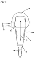
- FIG. 1 is an illustrated by an angle grinder power tool 12 shown in a view from above.
- the hand-held power tool 12 comprises a housing 68 and a main handle 66 integrated in the housing 68.
- the main handle 66 extends on a side 72 facing away from a tool 70 formed by a cutting disk in the direction of a longitudinal direction 74 of the hand-held power tool 12.
- an auxiliary handle device 10 is arranged, which extends transversely to the longitudinal direction 74 of the power tool 12.
- the auxiliary handle device 10 is shown with an auxiliary handle 14, a damping unit 16 and a fastening unit 78.
- the fastening unit 78 is provided for attachment of the auxiliary handle device 10 with the hand tool 12 and has for this purpose a bolt-shaped fastening element 80 to a screw connection with the power tool 12 on.
- the damping unit 16 comprises an actuator unit 18 formed by an electromagnetic actuator unit 18 for setting a damping characteristic and a sensor unit 46 for detecting a vibration characteristic.
- the auxiliary handle 14 has a grip sleeve 62 which, with a surface 84 facing inward in the radial direction 82, comprises a receiving region 64 of the auxiliary handle 14, in which the damping unit 16 is arranged.
- the electromagnetic actuator unit 18 has six electromagnetic actuator elements 20, 22, 24, 26, 28, 30, each comprising a coil 40 and a coil 40 movably mounted core 42 include.
- the electromagnetic actuator elements 20, 22, 24, 26, 28, 30 are each two groups of three electromagnetic actuator elements 20, 22, 24, 26, 28, 30, wherein a first group of electromagnetic actuator elements 20, 22, 24 at one along a main extension direction 38 of the auxiliary handle 14 of the fastening unit 78 facing end portion 34 of the auxiliary handle 14th and a second group of electromagnetic actuator elements 26, 28, 30 is arranged on an end region 36 of the auxiliary handle 14 facing away from the main extension direction 38 of the fastening unit 78.
- the electromagnetic actuator elements 20, 22, 24, 26, 28, 30 of the first and the second group are also uniformly spaced from each other in a circumferential direction 32 on a support member 60 of the auxiliary handle 14.
- the support element 60 is designed in two parts, wherein a portion 86 of the support element 60 facing the attachment unit 78 is formed integrally with the attachment element 80 of the attachment unit 78.
- both partial regions 86, 88 of the support element 60 are connected to one another in a middle region 90 of the auxiliary handle 14, for example screwed together by means of a thread, not shown.
- the core 42 of the electromagnetic actuator elements 20, 22, 24, 26, 28, 30 is in each case arranged on the surface 84 of the grip sleeve 62 which faces inward in the radial direction 82 and extends inwards in the radial direction 82.
- the core 42 is supported on the support element 60 in the radial direction 82 via a spring element 44 formed by a helical spring, which is arranged on the support element 60 ( FIG. 3 ).
- the coils 40 are each arranged on the support element 60, wherein the coils 40 surround the spring elements 44 and the spring elements 44 are arranged within a region 92 encompassed by the coils 40.
- each one of the coils 40 facing portion 94 of the core 42 is mounted within the area encompassed by the coil 40 area 92 so that the cores 42 during operation of the power tool 12, a magnetic force acts, depending on the direction and / or strength of an in The magnetic field generated by the coils 40, the cores 42 in the radial direction 82 outwardly or against a spring force of the spring member 44 moves inwardly ( FIG. 3 ).
- the electromagnetic actuator elements 20, 22, 24, 26, 28, 30 and the cores 42 are held by the spring elements 44 in a central rest position before operation of the power tool 12 and the auxiliary handle device 10.
- the grip sleeve 62 of the auxiliary handle 14 is exclusively by means of the electromagnetic actuator elements 20, 22, 24, 26, 28, 30 with respect to the fastening unit 78 or in relation to the Support member 60 mounted so that a direct transmission of vibration from the mounting unit 78 via the support member 60 to the grip sleeve 62 during operation of the power tool 12 is prevented.
- the sensor unit 46 also has six sensor elements 48, 50, 52, 54, of which in FIG. 2 only four can be seen, each formed by a capacitive distance sensor.
- three of the sensor elements 48, 50, 52, 54 are arranged to form a group, wherein a first group of sensor elements 48, 50 is arranged in a region 96 facing the main extension direction 38 of the fastening unit 78 and a second group of sensor elements 52, 54 in FIG a region 98 of the auxiliary handle 14 facing away from the main extension direction 38 of the fastening unit 78 is arranged.
- the sensor elements 48, 50, 52, 54 of a group are arranged in the circumferential direction 32 in each case at a distance from one another.
- the sensor elements 48, 50, 52, 54 each have a first sensor area 100 and a second sensor area 102.
- the first sensor region 100 is arranged on the support element 60 and the second sensor region 102 is arranged on the inwardly facing surface 84 of the grip sleeve 62, wherein the two sensor regions 100, 102 are arranged spaced apart in the radial direction 82.
- the two sensor regions 100, 102 form a capacitor, so that by means of a capacitance during operation of the handheld power tool 12 or the auxiliary handle device 10 a vibration characteristic based on a distance 104 and the changing distance 104 in the radial Direction 82 between the support member 60 and the grip sleeve 62 of the auxiliary handle 14 can be determined.
- the damping unit 16 furthermore has a control unit 56 which is provided for setting a damping characteristic within the electromagnetic actuator unit 18 or the electromagnetic actuator elements 20, 22, 24, 26, 28, 30 as a function of the sensed oscillation characteristic.
- a control unit 56 which is provided for setting a damping characteristic within the electromagnetic actuator unit 18 or the electromagnetic actuator elements 20, 22, 24, 26, 28, 30 as a function of the sensed oscillation characteristic.
- sensed oscillation characteristics of the sensor unit 46 or of the individual sensor elements 48, 50, 52, 54 are conducted to the control unit 56 via a data line, which determines a damping characteristic from the sensed oscillation characteristics by means of a processor of the control unit 56, not shown for the fixing unit 78 facing end portion 34 and for the fastening unit 78 facing away from the end portion 36 each have their own damping characteristic is determined.
- damping is set in the electromagnetic actuator unit 18 or in the individual electromagnetic actuator elements 20, 22, 22, 24, 26, 28, 30.
- a vibration movement which in operation of the power tool 12 via the fastening unit 78 is transmitted to the auxiliary handle 14, damped by means of a compensating movement of the electromagnetic actuator elements 20, 22, 22, 24, 26, 28, 30.
- a magnetic field is generated which acts on the movable cores 42 against a momentary oscillatory movement in the radial direction 82, so that the grip sleeve 62 is mounted at least partially vibration-decoupled with respect to the fastening unit 78 or the support element 60.
- the damping unit 16 has an energy storage means 58 which supplies the control unit 56, the sensor unit 46 and the electromagnetic actuator unit 18 with electrical energy via a power transmission line, not shown.
- the energy storage means 58 which is formed, for example, by a battery storing electrical energy in the form of chemical energy, is arranged inside the support element 60.
- the support element 60 has a recess 106 in the central region 90 along the main extension direction 38, wherein the recess 106 comprises a receiving region 108 for receiving the energy storage means 58.
- the two-part design makes it possible for an operator of the auxiliary handle device 10 to replace the energy storage means 58 by removing the portion 88 of the support element 60 facing away from the attachment unit 78. In principle, however, it is also conceivable that the energy storage means 58 via a power transmission line, not shown via a power supply of the power tool 12 during operation is rechargeable.
Landscapes
- Engineering & Computer Science (AREA)
- Mechanical Engineering (AREA)
- Percussion Or Vibration Massage (AREA)
- Finish Polishing, Edge Sharpening, And Grinding By Specific Grinding Devices (AREA)
- Vibration Prevention Devices (AREA)
Abstract
Description
Die Erfindung geht aus von einer Zusatzhandgriffvorrichtung nach dem Oberbegriff des Anspruchs 1.The invention is based on an auxiliary handle device according to the preamble of claim 1.
Es ist bereits eine Zusatzhandgriffvorrichtung für eine Handwerkzeugmaschine bekannt. Die Zusatzhandgriffvorrichtung weist einen Zusatzhandgriff und eine Dämpfungseinheit auf.There is already known an auxiliary handle device for a hand tool. The auxiliary handle device has an auxiliary handle and a damping unit.
Eine gattungsgemässe Vorrichtung ist aus
Die Erfindung geht aus von einer Zusatzhandgriffvorrichtung, insbesondere für eine Handwerkzeugmaschine, mit einem Zusatzhandgriff und einer Dämpfungseinheit.The invention relates to an auxiliary handle device, in particular for a hand tool, with an additional handle and a damping unit.
Es wird vorgeschlagen, dass die Dämpfungseinheit zumindest eine Aktoreinheit zu einer Einstellung einer Dämpfungskenngröße aufweist. In diesem Zusammenhang soll unter einem "Zusatzhandgriff" ein Bereich und/oder ein Bauteil und/oder ein Element verstanden werden, der bzw. das zu einem Anlegen, insbesondere einem Umgreifen, durch eine Hand oder mehrere Hände eines Bedieners zwecks einer Führung einer Handwerkzeugmaschine mittels der Zusatzhandgriffvorrichtung vorgesehen ist und insbesondere neben einem weiteren Handgriff, insbesondere dem Haupthandgriff, zusätzlich an der Handwerkzeugmaschine anbringbar ist, wobei die Zusatzhandgriffvorrichtung seitlich an der Handwerkzeugmaschine angeordnet ist und/oder werkzeuglos von einem Bediener an der Handwerkzeugmaschine montiert bzw. demontiert werden kann und/oder in einem vorderen, werkzeugnahen Bereich der Handwerkzeugmaschine angeordnet ist und/oder der Zusatzhandgriff stabförmig ausgebildet ist. Ferner soll unter einer "Aktoreinheit" insbesondere eine Einheit verstanden werden, die dazu vorgesehen ist, anhand einer erfassten Schwingungskenngröße einer auf die Zusatzhandgriffvorrichtung übertragenen Schwingung im Betrieb der Handwerkzeugmaschine eine Einstellung einer an die momentane Schwingungskenngröße angepassten Dämpfungskenngröße, insbesondere eine Stellkraft, die vorzugsweise einer Schwingungskraft entgegenwirkt, zu bewirken und dabei aktiv eine effektive Schwingungsdämpfung und/oder zumindest teilweise eine Schwingungsentkopplung des Zusatzhandgriffs von der Handwerkzeugmaschine zu erzielen. Des Weiteren soll unter einer "Dämpfungskenngröße" insbesondere eine Kenngröße zur Dämpfung einer Schwingung verstanden werden. Durch die erfindungsgemäße Ausgestaltung kann eine vorteilhafte Dämpfung des Zusatzhandgriffs, insbesondere eines Griffbereichs, und damit ein hoher Bedienkomfort für einen Bediener erreicht werden. Die erfmdungsgemäße Zusatzhandgriffvorrichtung ist grundsätzlich in Verbindung mit allen, dem Fachmann als sinnvoll erscheinenden Handwerkzeugmaschinen einsetzbar, bei denen insbesondere eine Führung von Handwerkzeugmaschinen mittels des Zusatzhandgriffs für einen Bediener erleichtert wird. Aufgrund ihrer Dämpfungseigenschaft ist die Zusatzhandgriffvorrichtung in Verbindung mit einer Winkelschleifmaschine besonders vorteilhaft.It is proposed that the damping unit has at least one actuator unit for setting a damping characteristic. In this context, an "additional handle" is to be understood as meaning an area and / or a component and / or an element which can be applied, in particular grasped, by one or more hands of an operator for the purpose of guiding a handheld power tool the auxiliary handle device is provided and in addition to another handle, in particular the main handle, in addition to the hand tool is attachable, wherein the auxiliary handle device is arranged laterally on the hand tool and / or can be assembled and disassembled without tools by an operator on the power tool and / or is arranged in a front, near the tool area of the power tool and / or the auxiliary handle is rod-shaped. Furthermore, an "actuator unit" should be understood to mean, in particular, a unit which is provided, on the basis of a detected oscillation characteristic, of an oscillation transmitted to the auxiliary handle device during operation of the handheld power tool an adjustment of a damping characteristic adapted to the instantaneous vibration characteristic variable, in particular a control force which preferably counteracts a vibration force, and thereby actively achieve effective vibration damping and / or at least partial vibration decoupling of the auxiliary handle from the handheld power tool. Furthermore, a "damping characteristic" should be understood in particular to be a parameter for damping a vibration. The embodiment according to the invention makes it possible to achieve an advantageous damping of the auxiliary handle, in particular of a grip area, and thus a high level of operating comfort for an operator. The erfmdungsgemäße auxiliary handle device is basically used in conjunction with all, the expert appears useful hand tool machines in which in particular a guidance of hand tool machines by means of the auxiliary handle for an operator is facilitated. Due to its damping characteristic, the auxiliary handle device is particularly advantageous in connection with an angle grinder.
Es können eine vorteilhafte Einstellung der Dämpfungskenngröße und eine insbesondere schnelle Reaktion auf eine Änderung einer Schwingungskenngröße im Betrieb vorteilhaft erreicht werden, wenn die Aktoreinheit zumindest teilweise von einer elektromagnetischen Aktoreinheit gebildet ist. Unter einer "elektromagnetischen Aktoreinheit" soll hierbei eine Aktoreinheit verstanden werden, bei der ein magnetisches Feld und/oder eine magnetische Kraft zur aktiven Einstellung einer Kenngröße ausgenutzt werden kann, wobei das magnetische Feld und/oder die magnetische Kraft durch eine Fließrichtung eines durch ein Bauteil der elektromagnetischen Aktoreinheit fließenden elektrischen Stroms und/oder eine Stromstärke eines durch das Bauteil der elektromagnetischen Aktoreinheit fließenden elektrischen Stroms erzeugt werden kann.An advantageous adjustment of the damping characteristic and a particularly rapid response to a change in a vibration characteristic during operation can advantageously be achieved if the actuator is at least partially formed by an electromagnetic actuator. An "electromagnetic actuator unit" is to be understood here as an actuator unit in which a magnetic field and / or a magnetic force can be utilized for the active setting of a parameter, the magnetic field and / or the magnetic force passing through a flow direction through a component the electromagnetic actuator unit flowing electrical current and / or a current strength of a current flowing through the component of the electromagnetic actuator unit electric current can be generated.
Des Weiteren wird vorgeschlagen, dass die elektromagnetische Aktoreinheit zumindest zwei elektromagnetische Aktorelemente aufweist, die in eine Umfangsrichtung gleichmäßig beabstandet zueinander angeordnet sind, wodurch eine vorteilhafte, in eine Umfangsrichtung gleichmäßige Schwingungsdämpfung und/oder zumindest teilweise Schwingungsentkopplung eines zumindest teilweisen Griffbereichs des Zusatzhandgriffs erreicht werden kann.Furthermore, it is proposed that the electromagnetic actuator unit has at least two electromagnetic actuator elements which are arranged uniformly spaced from each other in a circumferential direction, whereby an advantageous, in a circumferential direction uniform vibration damping and / or at least partial vibration isolation of an at least partial grip portion of the auxiliary handle can be achieved.
Es wird weiterhin vorgeschlagen, dass die elektromagnetische Aktoreinheit zumindest zwei elektromagnetische Aktorelemente aufweist, die an unterschiedlichen Endbereichen des Zusatzhandgriffs entlang einer Haupterstreckungsrichtung des Zusatzhandgriffs angeordnet sind. In diesem Zusammenhang soll unter einem "Endbereich des Zusatzhandgriffs" insbesondere ein Bereich des Zusatzhandgriffs verstanden werden, der entlang einer axialen Richtung bzw. der Haupterstreckungsrichtung an einem einem Ende des Zusatzhandgriffs zugewandten Bereich angeordnet ist und der entlang der axialen Richtung eine Erstreckung von vorzugsweise maximal 20 % und besonders vorteilhaft von maximal 10 % einer Längserstreckung des Zusatzhandgriffs umfasst. Ferner soll unter einer "Haupterstreckungsrichtung des Zusatzhandgriffs" insbesondere eine Erstreckungsrichtung verstanden werden, die vorzugsweise entlang einer Längsrichtung des Zusatzhandgriffs verläuft. Hierdurch kann eine vorteilhafte, an ein unterschiedliches Schwingungsverhalten des Zusatzhandgriffs entlang der Haupterstreckungsrichtung, die im Wesentlichen einer Vorzugsrichtung einer Schwingungsausbreitung innerhalb der Zusatzhandgriffvorrichtung entspricht, angepasste Schwingungsdämpfung einer Griffhülse und/oder eines Griffbereichs des Zusatzhandgriffs erreicht werden und damit eine effektive Schwingungsdämpfung im Betrieb der Handwerkzeugmaschine erzielt werden.It is further proposed that the electromagnetic actuator unit has at least two electromagnetic actuator elements, which are arranged at different end regions of the auxiliary handle along a main extension direction of the auxiliary handle. In this context, under an "end region of the auxiliary handle" in particular an area of the Additional handle to be understood, which is arranged along an axial direction or the main extension direction at one end of the auxiliary handle area and along the axial direction an extension of preferably not more than 20% and more preferably at most 10% of a longitudinal extent of the auxiliary handle. Furthermore, a "main direction of extension of the auxiliary handle" is to be understood as meaning, in particular, an extension direction which preferably runs along a longitudinal direction of the auxiliary handle. In this way, an advantageous, to a different vibration behavior of the auxiliary handle along the main extension direction, which corresponds essentially to a preferred direction of vibration propagation within the auxiliary handle device adapted vibration damping a grip sleeve and / or a handle portion of the auxiliary handle can be achieved and thus achieved an effective vibration damping during operation of the power tool become.
Ferner wird vorgeschlagen, dass zumindest eines der elektromagnetischen Aktorelemente zumindest teilweise eine Spule umfasst, wodurch konstruktiv einfach eine magnetische Kraft und/oder ein magnetisches Feld zur Einstellung und/oder zur Änderung einer Dämpfungskenngröße erzeugt werden kann. Vorzugsweise ist die Spule dazu vorgesehen, ein magnetisches Feld zu erzeugen.It is also proposed that at least one of the electromagnetic actuator elements at least partially comprises a coil, whereby structurally simple magnetic force and / or a magnetic field for setting and / or changing a damping characteristic can be generated. Preferably, the coil is intended to generate a magnetic field.
Vorteilhafterweise weist zumindest eines der elektromagnetischen Aktorelemente einen bewegbaren Kern auf, so dass insbesondere ein sich aufgrund einer Schwingung variierender Abstand besonders schnell ausgeglichen werden kann und insbesondere ein Griffbereich des Zusatzhandgriffs vorteilhaft zumindest teilweise schwingungsentkoppelt werden kann. Der bewegbare Kern kann dabei von einem Dauermagneten, von einem ferromagnetischen Material und/oder weiteren, dem Fachmann als sinnvoll erscheinenden Materialien gebildet sein. Besonders vorteilhaft ist hierbei der bewegbare Kern des elektromagnetischen Aktorelements zumindest teilweise innerhalb der Spule gelagert, so dass ein von der Spule erzeugtes magnetisches Feld direkt auf den bewegbaren Kern wirkt.Advantageously, at least one of the electromagnetic actuator elements to a movable core, so that in particular a varying due to a vibration distance can be compensated particularly quickly and in particular a handle portion of the auxiliary handle can be advantageous at least partially decoupled vibration. The movable core may be formed by a permanent magnet, by a ferromagnetic material and / or further, the expert appears useful as materials. In this case, the movable core of the electromagnetic actuator element is particularly advantageously stored at least partially within the coil, so that a magnetic field generated by the coil acts directly on the movable core.
Besonders vorteilhaft weist die elektromagnetische Aktoreinheit zumindest ein Federelement zu einer zumindest teilweisen Abstützung auf, wodurch die Spule und/oder besonders vorteilhaft der bewegbare Kern in einer vorteilhaften Ruheposition vor einer Schwingung des Zusatzhandgriffs bzw. vor einer Ausgleichsbewegung zur Schwingung des Zusatzhandgriffs abgestützt werden kann. Das Federelement kann dabei direkt an die Spule und/oder den bewegbaren Kern koppeln und/oder indirekt eine Abstützung bewirken. Grundsätzlich sind in einer alternativen Ausgestaltung der Erfindung weitere, insbesondere schwingungsdämpfende, dem Fachmann als sinnvoll erscheinende Abstützelemente und/oder Lagerelemente jederzeit denkbar.Particularly advantageously, the electromagnetic actuator unit at least one spring element to an at least partial support, whereby the coil and / or particularly advantageous the movable core can be supported in an advantageous rest position against a vibration of the auxiliary handle or before a compensating movement to the vibration of the auxiliary handle. The spring element can couple directly to the coil and / or the movable core and / or indirectly cause a support. Basically, in an alternative embodiment of the invention further, in particular vibration-damping, the expert appears reasonable sense supporting elements and / or bearing elements at any time conceivable.
In einer vorteilhaften Weiterbildung der Erfindung wird vorgeschlagen, dass die Dämpfungseinheit eine Sensoreinheit zur Erfassung einer Schwingungskenngröße aufweist, wodurch vorteilhaft eine effektive Anpassung einer Dämpfungskenngröße der Dämpfungseinheit, insbesondere der elektromagnetischen Aktoreinheit, an ein aktuelles Schwingungsverhalten der Handwerkzeugmaschine und/oder der Zusatzhandgriffvorrichtung erzielt werden kann.In an advantageous development of the invention it is proposed that the damping unit has a sensor unit for detecting a vibration characteristic, whereby advantageously an effective adaptation of a damping characteristic of the damping unit, in particular the electromagnetic actuator, to a current vibration behavior of the power tool and / or the auxiliary handle device can be achieved.
Weist zudem die Sensoreinheit zumindest ein Sensorelement auf, das von einem Abstandssensor gebildet ist, kann konstruktiv einfach und insbesondere kostengünstig die Schwingungskenngröße erfasst werden. Vorzugsweise ist der Abstandssensor von einem kapazitiven Abstandssensor gebildet, der zwei voneinander isolierte, elektrisch aufladbare Bauteile und/oder Elemente aufweist, wobei eine Distanz bzw. ein Abstand zwischen den beiden Bauteilen und/oder Elementen mittels einer Kapazität bestimmt werden kann. Es sind jedoch auch weitere, dem Fachmann als sinnvoll erscheinende Abstandssensoren, wie beispielsweise Abstandssensoren, die durch eine Laufzeit eines Signals einen Abstand ermitteln, in einer alternativen Ausgestaltung der Erfindung jederzeit denkbar.In addition, if the sensor unit has at least one sensor element which is formed by a distance sensor, the vibration characteristic variable can be detected in a structurally simple and, in particular, cost-effective manner. Preferably, the distance sensor is formed by a capacitive distance sensor having two mutually insulated, electrically chargeable components and / or elements, wherein a distance or a distance between the two components and / or elements can be determined by means of a capacitance. However, other distance sensors which appear reasonable to the person skilled in the art, for example distance sensors which determine a distance by a transit time of a signal, are also conceivable at any time in an alternative embodiment of the invention.
Weist die Sensoreinheit zumindest zwei Sensorelemente auf, die an unterschiedlichen Bereichen des Zusatzhandgriffs entlang einer Haupterstreckungsrichtung des Zusatzhandgriffs angeordnet sind, kann vorteilhaft ein sich veränderndes Schwingungsverhalten entlang der Haupterstreckungsrichtung bzw. entlang einer Vorzugsrichtung einer Schwingungsausbreitung innerhalb des Zusatzhandgriffs erfasst werden.If the sensor unit has at least two sensor elements which are arranged on different regions of the auxiliary handle along a main direction of extension of the auxiliary handle, advantageously a changing vibration behavior along the main extension direction or along a preferred direction of vibration propagation within the auxiliary handle can be detected.
Zudem kann ein Schwingungsverhalten des Zusatzhandgriffs besonders genau ermittelt werden, wenn die Sensoreinheit zumindest zwei Sensorelemente aufweist, die in eine Umfangsrichtung gleichmäßig beabstandet zueinander angeordnet sind.In addition, a vibration behavior of the auxiliary handle can be determined particularly accurately when the sensor unit has at least two sensor elements which are arranged uniformly spaced from one another in a circumferential direction.
Des Weiteren wird vorgeschlagen, dass die Dämpfungseinheit eine Steuereinheit aufweist, die zu einer Einstellung einer Dämpfungskenngröße in Abhängigkeit einer sensierten Schwingungskenngröße vorgesehen ist, wodurch eine insbesondere automatische Einstellung der Dämpfungskenngröße erzielt werden kann. In diesem Zusammenhang soll unter einer "Steuereinheit" insbesondere eine Einheit verstanden werden, die von einer Recheneinheit, einer Auswerteeinheit, einer Kontrolleinheit und/oder einer Regeleinheit gebildet ist, wobei eine Steuereinheit sowohl von einem Prozessor allein als auch insbesondere von einem Prozessor und weiteren Elektronikbauteilen, wie Speichermitteln, gebildet sein kann. Zudem ist es auch denkbar, dass die Steuereinheit und die Sensoreinheit zumindest teilweise einstückig ausgebildet sind.Furthermore, it is proposed that the damping unit has a control unit which is provided for setting a damping characteristic as a function of a sensed oscillation characteristic, whereby a particularly automatic adjustment of the damping characteristic can be achieved. In this context, a "control unit" should be understood to mean, in particular, a unit which comprises a computing unit, an evaluation unit, a control unit and / or a control unit is formed, wherein a control unit can be formed both by a processor alone and in particular by a processor and further electronic components, such as storage means. In addition, it is also conceivable that the control unit and the sensor unit are at least partially formed in one piece.
Weist die Dämpfungseinheit zumindest ein Energiespeichermittel auf, das zu einer Energieversorgung der Steuereinheit und/oder der elektromagnetischen Aktoreinheit und/oder der Sensoreinheit vorgesehen ist, kann ein Betrieb der Dämpfungseinheit unabhängig von einer Spannungsversorgung der Handwerkzeugmaschine erzielt werden. Des Weiteren kann das Energiespeichermittel vorteilhaft von einem wieder aufladbaren Energiespeichermittel gebildet sein. Grundsätzlich ist es zudem auch denkbar, die Steuereinheit und/oder die elektromagnetische Aktoreinheit über die Handwerkzeugmaschine mit elektrischer Energie zu versorgen.If the damping unit has at least one energy storage device which is provided for supplying energy to the control unit and / or the electromagnetic actuator unit and / or the sensor unit, operation of the damping unit can be achieved independently of a power supply of the handheld power tool. Furthermore, the energy storage means may advantageously be formed by a rechargeable energy storage means. In principle, it is also conceivable to supply the control unit and / or the electromagnetic actuator unit with electrical energy via the handheld power tool.
Ferner wird vorgeschlagen, dass der Zusatzhandgriff zumindest ein Stützelement aufweist, das zu einer Aufnahme des Energiespeichermittels vorgesehen ist. Es kann hierdurch eine besonders kompakte und Platz sparende Anordnung des Energiespeichermittels innerhalb der Zusatzhandgriffvorrichtung bzw. innerhalb der Dämpfungseinheit erreicht werden. Vorzugsweise ist das Stützelement von einem Element gebildet, das sich entlang der Haupterstreckungsrichtung des Zusatzhandgriffs erstreckt und dem Zusatzhandgriff entlang der Haupterstreckungsrichtung eine für eine Führung der Handwerkzeugmaschine mittels des Zusatzhandgriffs erforderliche Steifigkeit und Stabilität verleiht.It is also proposed that the auxiliary handle has at least one support element which is provided for receiving the energy storage means. It can thereby be achieved a particularly compact and space-saving arrangement of the energy storage means within the auxiliary handle device or within the damping unit. Preferably, the support element is formed by an element which extends along the main direction of extension of the auxiliary handle and gives the auxiliary handle along the main direction of extension for a guidance of the power tool by means of the auxiliary handle required rigidity and stability.
Weiterhin wird vorgeschlagen, dass der Zusatzhandgriff eine Griffhülse aufweist, die einen Aufnahmebereich zu einer zumindest teilweisen Aufnahme der Dämpfungseinheit bildet, wodurch eine konstruktiv einfache Aufnahme und eine kompakte, insbesondere Platz sparende Anordnung der Dämpfungseinheit innerhalb der Zusatzhandgriffvorrichtung erreicht werden können.Furthermore, it is proposed that the auxiliary handle has a grip sleeve, which forms a receiving area for at least partially receiving the damping unit, whereby a structurally simple recording and a compact, especially space-saving arrangement of the damping unit can be achieved within the auxiliary handle device.
Weitere Vorteile ergeben sich aus der folgenden Zeichnungsbeschreibung. In der Zeichnung ist ein Ausführungsbeispiel der Erfindung dargestellt. Die Zeichnung, die Beschreibung und die Ansprüche enthalten zahlreiche Merkmale in Kombination. Der Fachmann wird die Merkmale zweckmä-Bigerweise auch einzeln betrachten und zu sinnvollen weiteren Kombinationen zusammenfassen.Further advantages emerge from the following description of the drawing. In the drawing, an embodiment of the invention is shown. The drawing, the description and the claims contain numerous features in combination. The person skilled in the art expediently also individually considers the features and combines them into meaningful further combinations.
Es zeigen:
- Fig. 1
- eine Handwerkzeugmaschine mit einer erfindungsgemäßen Zusatzhandgriffvorrichtung in einer schematischen Darstellung,
- Fig. 2
- die Zusatzhandgriffvorrichtung mit einer Dämpfungseinheit in einer perspektivischen Schnittdarstellung und
- Fig. 3
- die Zusatzhandgriffvorrichtung aus
Figur 2 in einer Schnittdarstellung.
- Fig. 1
- a hand tool with an additional handle device according to the invention in a schematic representation,
- Fig. 2
- the additional handle device with a damping unit in a perspective sectional view and
- Fig. 3
- the auxiliary handle device
FIG. 2 in a sectional view.
In
In
Die elektromagnetischen Aktorelemente 20, 22, 24, 26, 28, 30 der ersten und der zweiten Gruppe sind zudem in einer Umfangsrichtung 32 gleichmäßig zueinander beabstandet an einem Stützelement 60 des Zusatzhandgriffs 14 angeordnet. Das Stützelement 60 ist zweiteilig ausgebildet, wobei ein der Befestigungseinheit 78 zugewandter Teilbereich 86 des Stützelements 60 einstückig mit dem Befestigungselement 80 der Befestigungseinheit 78 ausgebildet ist. Entlang der Haupterstreckungsrichtung 38 sind in einem mittleren Bereich 90 des Zusatzhandgriffs 14 beide Teilbereiche 86, 88 des Stützelements 60 miteinander verbunden, wie beispielsweise mittels eines nicht näher dargestellten Gewindes miteinander verschraubt.The
Der Kern 42 der elektromagnetischen Aktorelemente 20, 22, 24, 26, 28, 30 ist jeweils an der in radialer Richtung 82 nach innen gewandten Oberfläche 84 der Griffhülse 62 angeordnet und erstreckt sich von dieser in radialer Richtung 82 nach innen. Zudem ist der Kern 42 in radialer Richtung 82 über ein von einer Schraubenfeder gebildetes Federelement 44, das an dem Stützelement 60 angeordnet ist, an dem Stützelement 60 abgestützt (
Die Griffhülse 62 des Zusatzhandgriffs 14 ist ausschließlich mittels der elektromagnetischen Aktorelemente 20, 22, 24, 26, 28, 30 im Bezug auf die Befestigungseinheit 78 bzw. im Bezug auf das Stützelement 60 gelagert, so dass eine direkte Schwingungsübertragung von der Befestigungseinheit 78 über das Stützelement 60 auf die Griffhülse 62 im Betrieb der Handwerkzeugmaschine 12 verhindert ist.The
Die Sensoreinheit 46 weist ebenfalls sechs Sensorelemente 48, 50, 52, 54 auf, von denen in
Die Dämpfungseinheit 16 weist des Weiteren eine Steuereinheit 56 auf, die zu einer Einstellung einer Dämpfungskenngröße innerhalb der elektromagnetischen Aktoreinheit 18 bzw. den elektromagnetischen Aktorelementen 20, 22, 24, 26, 28, 30 in Abhängigkeit der sensierten Schwingungskenngröße vorgesehen ist. Hierzu werden sensierte Schwingungskenngrößen der Sensoreinheit 46 bzw. der einzelnen Sensorelemente 48, 50, 52, 54 über eine nicht näher dargestellte Datenleitung an die Steuereinheit 56 geleitet, die aus den sensierten Schwingungskenngrößen eine Dämpfungskenngröße mittels eines nicht näher dargestellten Prozessors der Steuereinheit 56 ermittelt, wobei für den der Befestigungseinheit 78 zugewandten Endbereich 34 und für den der Befestigungseinheit 78 abgewandten Endbereich 36 jeweils eine eigene Dämpfungskenngröße ermittelt wird. Mittels der Dämpfungskenngröße wird in der elektromagnetischen Aktoreinheit 18 bzw. in den einzelnen elektromagnetischen Aktorelementen 20, 22, 22, 24, 26, 28, 30 eine Dämpfung eingestellt. Hierbei wird eine Schwingungsbewegung, die im Betrieb von der Handwerkzeugmaschine 12 über die Befestigungseinheit 78 auf den Zusatzhandgriff 14 übertragen wird, mittels einer Ausgleichsbewegung der elektromagnetischen Aktorelemente 20, 22, 22, 24, 26, 28, 30 gedämpft. In den Spulen 40 wird dabei ein Magnetfeld erzeugt, das auf die bewegbaren Kerne 42 entgegen einer momentanen Schwingungsbewegung in radialer Richtung 82 wirkt, so dass die Griffhülse 62 zumindest teilweise schwingungsentkoppelt bezüglich der Befestigungseinheit 78 bzw. des Stützelements 60 gelagert ist.The damping
Zu einer von der Handwerkzeugmaschine 12 unabhängigen Energieversorgung weist die Dämpfungseinheit 16 ein Energiespeichermittel 58 auf, das über eine nicht näher dargestellte Energieübertragungsleitung die Steuereinheit 56, die Sensoreinheit 46 und die elektromagnetische Aktoreinheit 18 mit elektrischer Energie versorgt. Das Energiespeichermittel 58, das beispielsweise von einer Batterie, die elektrische Energie in Form von chemischer Energie speichert, gebildet ist, ist innerhalb des Stützelements 60 angeordnet. Hierzu weist das Stützelement 60 eine Aussparung 106 in dem mittleren Bereich 90 entlang der Haupterstreckungsrichtung 38 auf, wobei die Aussparung 106 einen Aufnahmebereich 108 zur Aufnahme des Energiespeichermittels 58 umfasst. Die zweiteilige Ausbildung ermöglicht es für einen Bediener der Zusatzhandgriffvorrichtung 10, das Energiespeichermittel 58 durch Entfernen des der Befestigungseinheit 78 abgewandten Teilbereichs 88 des Stützelements 60 auszuwechseln. Grundsätzlich ist es jedoch auch denkbar, dass das Energiespeichermittel 58 über eine nicht näher dargestellte Energieübertragungsleitung über eine Energieversorgung der Handwerkzeugmaschine 12 im Betrieb aufladbar ist.To an independent of the
Claims (14)
- Auxiliary handle apparatus, in particular for a handheld power tool (12), having an auxiliary handle (14), which has a handle sleeve (62) and a fastening unit (78), and having a damping unit (16) for decoupling vibrations of a handle region of the handle sleeve (62) relative to the fastening unit (78), with the damping unit (16) having at least one actuator unit (18) for setting a damping characteristic variable, with the actuator unit (18) being formed at least partly by an electromagnetic actuator unit (18), characterized in that the electromagnetic actuator unit (18) has at least two electromagnetic actuator elements (20, 22, 24, 26, 28, 30) which are arranged at a uniform distance from one another in a circumferential direction (32) of the handle sleeve (62).
- Auxiliary handle apparatus according to Claim 1, characterized in that the electromagnetic actuator unit (18) has at least two electromagnetic actuator elements (20, 22, 24, 26, 28, 30) which are arranged at different end regions (34, 36) of the auxiliary handle (14) along a main direction (38) of extent of the auxiliary handle (14).
- Auxiliary handle apparatus according to either of the preceding claims, characterized in that at least one of the electromagnetic actuator elements (20, 22, 24, 26, 28, 30) at least partially surrounds a coil (40).
- Auxiliary handle apparatus at least according to Claim 3, characterized in that at least one of the electromagnetic actuator elements (20, 22, 24, 26, 28, 30) at least partially has a movable core (42).
- Auxiliary handle apparatus according to one of the preceding claims, characterized in that the electromagnetic actuator unit (18) has at least one spring element (44) for providing at least partial support.
- Auxiliary handle apparatus according to one of the preceding claims, characterized in that the damping unit (16) has a sensor unit (46) for detecting a vibration characteristic variable.
- Auxiliary handle apparatus at least according to Claim 6, characterized in that the sensor unit (46) has at least one sensor element (48, 50, 52, 54) which is formed by a distance sensor.
- Auxiliary handle apparatus at least according to Claim 6, characterized in that the sensor unit (46) has at least two sensor elements (48, 50, 52, 54) which are arranged on different regions (96, 98) of the auxiliary handle (14) along a main direction (38) of extent of the auxiliary handle (14).
- Auxiliary handle apparatus at least according to Claim 6, characterized in that the sensor unit (46) has at least two sensor elements (48, 50, 52, 54) which are arranged at a uniform distance from one another in a circumferential direction (32).
- Auxiliary handle apparatus according to one of the preceding claims, characterized in that the damping unit (16) has a control unit (56) which is intended to set a damping characteristic variable as a function of a sensed vibration characteristic variable.
- Auxiliary handle apparatus at least according to Claim 6 and/or 10, characterized in that the damping unit (16) has at least one energy storage means (58) which is intended to supply energy to the control unit (56) and/or to the electromagnetic actuator unit (18) and/or to the sensor unit (46).
- Auxiliary handle apparatus at least according to Claim 11, characterized in that the auxiliary handle (14) has at least one supporting element (60) which is intended to hold the energy storage means (58).
- Auxiliary handle apparatus according to one of the preceding claims, characterized in that the auxiliary handle (14) has a handle sleeve (62) which forms a holding region (64) for at least partially holding the damping unit (16).
- Handheld power tool, in particular an angle grinder, having a main handle (66) and an auxiliary handle apparatus (10) according to one of the preceding claims.
Applications Claiming Priority (2)
| Application Number | Priority Date | Filing Date | Title |
|---|---|---|---|
| DE102007055634A DE102007055634A1 (en) | 2007-11-21 | 2007-11-21 | Auxiliary handle device |
| PCT/EP2008/064092 WO2009065681A2 (en) | 2007-11-21 | 2008-10-20 | Auxiliary handle device |
Publications (2)
| Publication Number | Publication Date |
|---|---|
| EP2214871A2 EP2214871A2 (en) | 2010-08-11 |
| EP2214871B1 true EP2214871B1 (en) | 2011-12-28 |
Family
ID=40219023
Family Applications (1)
| Application Number | Title | Priority Date | Filing Date |
|---|---|---|---|
| EP08851439A Not-in-force EP2214871B1 (en) | 2007-11-21 | 2008-10-20 | Auxiliary handle device |
Country Status (4)
| Country | Link |
|---|---|
| EP (1) | EP2214871B1 (en) |
| AT (1) | ATE538906T1 (en) |
| DE (1) | DE102007055634A1 (en) |
| WO (1) | WO2009065681A2 (en) |
Family Cites Families (7)
| Publication number | Priority date | Publication date | Assignee | Title |
|---|---|---|---|---|
| JPS57150014A (en) * | 1980-06-21 | 1982-09-16 | Makoto Minamidate | Oscillation control type handle device |
| DE4011124A1 (en) * | 1990-04-06 | 1991-10-10 | Metabowerke Kg | VIBRATION DAMPED HANDLE |
| DE19646622B4 (en) * | 1996-11-12 | 2004-07-01 | Wacker Construction Equipment Ag | Tool that can be carried in one movement |
| DE10130088C2 (en) * | 2001-06-21 | 2003-10-16 | Hilti Ag | Striking electric hand tool device with active vibration damping |
| DE10361481B4 (en) * | 2003-07-22 | 2006-08-17 | Fraunhofer-Gesellschaft zur Förderung der angewandten Forschung e.V. | Modular interface to dampen mechanical vibrations, between structures in automotive and aerospace applications and the like, has a base with a tension support to take a loading link between them together with energy conversion actuators |
| DE102005031074A1 (en) * | 2005-06-24 | 2007-01-04 | C. & E. Fein Gmbh | Powered hand tool with damping device |
| DE102005000202A1 (en) * | 2005-12-23 | 2007-06-28 | Hilti Ag | Handle with vibration reducing device |
-
2007
- 2007-11-21 DE DE102007055634A patent/DE102007055634A1/en not_active Withdrawn
-
2008
- 2008-10-20 AT AT08851439T patent/ATE538906T1/en active
- 2008-10-20 WO PCT/EP2008/064092 patent/WO2009065681A2/en active Application Filing
- 2008-10-20 EP EP08851439A patent/EP2214871B1/en not_active Not-in-force
Also Published As
| Publication number | Publication date |
|---|---|
| DE102007055634A1 (en) | 2009-05-28 |
| WO2009065681A3 (en) | 2009-12-03 |
| EP2214871A2 (en) | 2010-08-11 |
| WO2009065681A2 (en) | 2009-05-28 |
| ATE538906T1 (en) | 2012-01-15 |
Similar Documents
| Publication | Publication Date | Title |
|---|---|---|
| DE4000861C3 (en) | Hand-held impact drill with vibration damping | |
| EP3319748B1 (en) | Device for generating an ultrasonic oscillation in a tool and measuring oscillation parameters | |
| DE102017123167A1 (en) | Electric power tool and method for assembling an electric power tool | |
| DE202017105258U1 (en) | Battery Pack Adapter | |
| EP2253430A1 (en) | Electric tool machine, in particular handheld hammer drill | |
| DE102011089673A1 (en) | Hand tool | |
| DE112014006502T5 (en) | impact tool | |
| EP3500405B1 (en) | Hand-held power tool and method for damping a hand-held power tool | |
| WO2008155151A1 (en) | Machine hand tool housing unit | |
| DE102018109002A1 (en) | impact tool | |
| EP2262617A1 (en) | Counter-vibration device | |
| DE102019124134A1 (en) | Work tool | |
| EP2205407B1 (en) | Auxiliary handle device | |
| DE102021121505A1 (en) | DRILLING TOOL | |
| DE102020128432A1 (en) | TOOL WITH MOVABLE COMPONENT | |
| DE202014009989U1 (en) | Oszillationswerkzeugmaschine | |
| DE102012221517A1 (en) | Hand machine tool apparatus of powered hand tool e.g. drilling and/or percussion hammer, has sensor unit that is provided for detection of characteristic variable at portion of compensation unit | |
| EP2214871B1 (en) | Auxiliary handle device | |
| DE102015226415A1 (en) | Hand tool | |
| DE102021105540A1 (en) | Power tool | |
| EP2205406B1 (en) | Auxiliary handle device | |
| EP1221359A1 (en) | Vibration isolating device | |
| DE102008041003A1 (en) | Handle device | |
| DE102020115354A1 (en) | Impact tool | |
| DE202017101409U1 (en) | Auxiliary handle and working tool |
Legal Events
| Date | Code | Title | Description |
|---|---|---|---|
| PUAI | Public reference made under article 153(3) epc to a published international application that has entered the european phase |
Free format text: ORIGINAL CODE: 0009012 |
|
| 17P | Request for examination filed |
Effective date: 20100621 |
|
| AK | Designated contracting states |
Kind code of ref document: A2 Designated state(s): AT BE BG CH CY CZ DE DK EE ES FI FR GB GR HR HU IE IS IT LI LT LU LV MC MT NL NO PL PT RO SE SI SK TR |
|
| AX | Request for extension of the european patent |
Extension state: AL BA MK RS |
|
| DAX | Request for extension of the european patent (deleted) | ||
| GRAP | Despatch of communication of intention to grant a patent |
Free format text: ORIGINAL CODE: EPIDOSNIGR1 |
|
| GRAS | Grant fee paid |
Free format text: ORIGINAL CODE: EPIDOSNIGR3 |
|
| GRAA | (expected) grant |
Free format text: ORIGINAL CODE: 0009210 |
|
| AK | Designated contracting states |
Kind code of ref document: B1 Designated state(s): AT BE BG CH CY CZ DE DK EE ES FI FR GB GR HR HU IE IS IT LI LT LU LV MC MT NL NO PL PT RO SE SI SK TR |
|
| REG | Reference to a national code |
Ref country code: GB Ref legal event code: FG4D Free format text: NOT ENGLISH |
|
| REG | Reference to a national code |
Ref country code: CH Ref legal event code: EP |
|
| REG | Reference to a national code |
Ref country code: AT Ref legal event code: REF Ref document number: 538906 Country of ref document: AT Kind code of ref document: T Effective date: 20120115 |
|
| REG | Reference to a national code |
Ref country code: IE Ref legal event code: FG4D |
|
| REG | Reference to a national code |
Ref country code: DE Ref legal event code: R096 Ref document number: 502008006014 Country of ref document: DE Effective date: 20120308 |
|
| REG | Reference to a national code |
Ref country code: NL Ref legal event code: VDEP Effective date: 20111228 |
|
| PG25 | Lapsed in a contracting state [announced via postgrant information from national office to epo] |
Ref country code: LT Free format text: LAPSE BECAUSE OF FAILURE TO SUBMIT A TRANSLATION OF THE DESCRIPTION OR TO PAY THE FEE WITHIN THE PRESCRIBED TIME-LIMIT Effective date: 20111228 Ref country code: NO Free format text: LAPSE BECAUSE OF FAILURE TO SUBMIT A TRANSLATION OF THE DESCRIPTION OR TO PAY THE FEE WITHIN THE PRESCRIBED TIME-LIMIT Effective date: 20120328 |
|
| LTIE | Lt: invalidation of european patent or patent extension |
Effective date: 20111228 |
|
| PG25 | Lapsed in a contracting state [announced via postgrant information from national office to epo] |
Ref country code: SE Free format text: LAPSE BECAUSE OF FAILURE TO SUBMIT A TRANSLATION OF THE DESCRIPTION OR TO PAY THE FEE WITHIN THE PRESCRIBED TIME-LIMIT Effective date: 20111228 Ref country code: HR Free format text: LAPSE BECAUSE OF FAILURE TO SUBMIT A TRANSLATION OF THE DESCRIPTION OR TO PAY THE FEE WITHIN THE PRESCRIBED TIME-LIMIT Effective date: 20111228 Ref country code: GR Free format text: LAPSE BECAUSE OF FAILURE TO SUBMIT A TRANSLATION OF THE DESCRIPTION OR TO PAY THE FEE WITHIN THE PRESCRIBED TIME-LIMIT Effective date: 20120329 Ref country code: SI Free format text: LAPSE BECAUSE OF FAILURE TO SUBMIT A TRANSLATION OF THE DESCRIPTION OR TO PAY THE FEE WITHIN THE PRESCRIBED TIME-LIMIT Effective date: 20111228 Ref country code: LV Free format text: LAPSE BECAUSE OF FAILURE TO SUBMIT A TRANSLATION OF THE DESCRIPTION OR TO PAY THE FEE WITHIN THE PRESCRIBED TIME-LIMIT Effective date: 20111228 |
|
| PG25 | Lapsed in a contracting state [announced via postgrant information from national office to epo] |
Ref country code: CY Free format text: LAPSE BECAUSE OF FAILURE TO SUBMIT A TRANSLATION OF THE DESCRIPTION OR TO PAY THE FEE WITHIN THE PRESCRIBED TIME-LIMIT Effective date: 20111228 |
|
| REG | Reference to a national code |
Ref country code: IE Ref legal event code: FD4D |
|
| PG25 | Lapsed in a contracting state [announced via postgrant information from national office to epo] |
Ref country code: IE Free format text: LAPSE BECAUSE OF FAILURE TO SUBMIT A TRANSLATION OF THE DESCRIPTION OR TO PAY THE FEE WITHIN THE PRESCRIBED TIME-LIMIT Effective date: 20111228 Ref country code: IS Free format text: LAPSE BECAUSE OF FAILURE TO SUBMIT A TRANSLATION OF THE DESCRIPTION OR TO PAY THE FEE WITHIN THE PRESCRIBED TIME-LIMIT Effective date: 20120428 Ref country code: NL Free format text: LAPSE BECAUSE OF FAILURE TO SUBMIT A TRANSLATION OF THE DESCRIPTION OR TO PAY THE FEE WITHIN THE PRESCRIBED TIME-LIMIT Effective date: 20111228 Ref country code: SK Free format text: LAPSE BECAUSE OF FAILURE TO SUBMIT A TRANSLATION OF THE DESCRIPTION OR TO PAY THE FEE WITHIN THE PRESCRIBED TIME-LIMIT Effective date: 20111228 Ref country code: CZ Free format text: LAPSE BECAUSE OF FAILURE TO SUBMIT A TRANSLATION OF THE DESCRIPTION OR TO PAY THE FEE WITHIN THE PRESCRIBED TIME-LIMIT Effective date: 20111228 Ref country code: BG Free format text: LAPSE BECAUSE OF FAILURE TO SUBMIT A TRANSLATION OF THE DESCRIPTION OR TO PAY THE FEE WITHIN THE PRESCRIBED TIME-LIMIT Effective date: 20120328 Ref country code: EE Free format text: LAPSE BECAUSE OF FAILURE TO SUBMIT A TRANSLATION OF THE DESCRIPTION OR TO PAY THE FEE WITHIN THE PRESCRIBED TIME-LIMIT Effective date: 20111228 |
|
| PG25 | Lapsed in a contracting state [announced via postgrant information from national office to epo] |
Ref country code: PT Free format text: LAPSE BECAUSE OF FAILURE TO SUBMIT A TRANSLATION OF THE DESCRIPTION OR TO PAY THE FEE WITHIN THE PRESCRIBED TIME-LIMIT Effective date: 20120430 Ref country code: PL Free format text: LAPSE BECAUSE OF FAILURE TO SUBMIT A TRANSLATION OF THE DESCRIPTION OR TO PAY THE FEE WITHIN THE PRESCRIBED TIME-LIMIT Effective date: 20111228 Ref country code: RO Free format text: LAPSE BECAUSE OF FAILURE TO SUBMIT A TRANSLATION OF THE DESCRIPTION OR TO PAY THE FEE WITHIN THE PRESCRIBED TIME-LIMIT Effective date: 20111228 |
|
| PG25 | Lapsed in a contracting state [announced via postgrant information from national office to epo] |
Ref country code: DK Free format text: LAPSE BECAUSE OF FAILURE TO SUBMIT A TRANSLATION OF THE DESCRIPTION OR TO PAY THE FEE WITHIN THE PRESCRIBED TIME-LIMIT Effective date: 20111228 |
|
| PLBE | No opposition filed within time limit |
Free format text: ORIGINAL CODE: 0009261 |
|
| STAA | Information on the status of an ep patent application or granted ep patent |
Free format text: STATUS: NO OPPOSITION FILED WITHIN TIME LIMIT |
|
| PG25 | Lapsed in a contracting state [announced via postgrant information from national office to epo] |
Ref country code: IT Free format text: LAPSE BECAUSE OF FAILURE TO SUBMIT A TRANSLATION OF THE DESCRIPTION OR TO PAY THE FEE WITHIN THE PRESCRIBED TIME-LIMIT Effective date: 20111228 |
|
| 26N | No opposition filed |
Effective date: 20121001 |
|
| REG | Reference to a national code |
Ref country code: DE Ref legal event code: R097 Ref document number: 502008006014 Country of ref document: DE Effective date: 20121001 |
|
| BERE | Be: lapsed |
Owner name: ROBERT BOSCH G.M.B.H. Effective date: 20121031 |
|
| PG25 | Lapsed in a contracting state [announced via postgrant information from national office to epo] |
Ref country code: ES Free format text: LAPSE BECAUSE OF FAILURE TO SUBMIT A TRANSLATION OF THE DESCRIPTION OR TO PAY THE FEE WITHIN THE PRESCRIBED TIME-LIMIT Effective date: 20120408 |
|
| PG25 | Lapsed in a contracting state [announced via postgrant information from national office to epo] |
Ref country code: MC Free format text: LAPSE BECAUSE OF NON-PAYMENT OF DUE FEES Effective date: 20121031 |
|
| REG | Reference to a national code |
Ref country code: CH Ref legal event code: PL |
|
| PG25 | Lapsed in a contracting state [announced via postgrant information from national office to epo] |
Ref country code: FI Free format text: LAPSE BECAUSE OF FAILURE TO SUBMIT A TRANSLATION OF THE DESCRIPTION OR TO PAY THE FEE WITHIN THE PRESCRIBED TIME-LIMIT Effective date: 20111228 |
|
| REG | Reference to a national code |
Ref country code: FR Ref legal event code: ST Effective date: 20130628 |
|
| PG25 | Lapsed in a contracting state [announced via postgrant information from national office to epo] |
Ref country code: LI Free format text: LAPSE BECAUSE OF NON-PAYMENT OF DUE FEES Effective date: 20121031 Ref country code: CH Free format text: LAPSE BECAUSE OF NON-PAYMENT OF DUE FEES Effective date: 20121031 Ref country code: BE Free format text: LAPSE BECAUSE OF NON-PAYMENT OF DUE FEES Effective date: 20121031 |
|
| PG25 | Lapsed in a contracting state [announced via postgrant information from national office to epo] |
Ref country code: FR Free format text: LAPSE BECAUSE OF NON-PAYMENT OF DUE FEES Effective date: 20121031 |
|
| PG25 | Lapsed in a contracting state [announced via postgrant information from national office to epo] |
Ref country code: MT Free format text: LAPSE BECAUSE OF FAILURE TO SUBMIT A TRANSLATION OF THE DESCRIPTION OR TO PAY THE FEE WITHIN THE PRESCRIBED TIME-LIMIT Effective date: 20111228 |
|
| PGFP | Annual fee paid to national office [announced via postgrant information from national office to epo] |
Ref country code: GB Payment date: 20131022 Year of fee payment: 6 |
|
| PG25 | Lapsed in a contracting state [announced via postgrant information from national office to epo] |
Ref country code: TR Free format text: LAPSE BECAUSE OF FAILURE TO SUBMIT A TRANSLATION OF THE DESCRIPTION OR TO PAY THE FEE WITHIN THE PRESCRIBED TIME-LIMIT Effective date: 20111228 |
|
| PGFP | Annual fee paid to national office [announced via postgrant information from national office to epo] |
Ref country code: DE Payment date: 20131217 Year of fee payment: 6 |
|
| PG25 | Lapsed in a contracting state [announced via postgrant information from national office to epo] |
Ref country code: LU Free format text: LAPSE BECAUSE OF NON-PAYMENT OF DUE FEES Effective date: 20121020 |
|
| PG25 | Lapsed in a contracting state [announced via postgrant information from national office to epo] |
Ref country code: HU Free format text: LAPSE BECAUSE OF FAILURE TO SUBMIT A TRANSLATION OF THE DESCRIPTION OR TO PAY THE FEE WITHIN THE PRESCRIBED TIME-LIMIT Effective date: 20081020 |
|
| REG | Reference to a national code |
Ref country code: AT Ref legal event code: MM01 Ref document number: 538906 Country of ref document: AT Kind code of ref document: T Effective date: 20131020 |
|
| PG25 | Lapsed in a contracting state [announced via postgrant information from national office to epo] |
Ref country code: AT Free format text: LAPSE BECAUSE OF NON-PAYMENT OF DUE FEES Effective date: 20131020 |
|
| REG | Reference to a national code |
Ref country code: DE Ref legal event code: R119 Ref document number: 502008006014 Country of ref document: DE |
|
| GBPC | Gb: european patent ceased through non-payment of renewal fee |
Effective date: 20141020 |
|
| PG25 | Lapsed in a contracting state [announced via postgrant information from national office to epo] |
Ref country code: DE Free format text: LAPSE BECAUSE OF NON-PAYMENT OF DUE FEES Effective date: 20150501 Ref country code: GB Free format text: LAPSE BECAUSE OF NON-PAYMENT OF DUE FEES Effective date: 20141020 |