EP2214279A2 - Device for connecting armoring wires of cable - Google Patents
Device for connecting armoring wires of cable Download PDFInfo
- Publication number
- EP2214279A2 EP2214279A2 EP09012312A EP09012312A EP2214279A2 EP 2214279 A2 EP2214279 A2 EP 2214279A2 EP 09012312 A EP09012312 A EP 09012312A EP 09012312 A EP09012312 A EP 09012312A EP 2214279 A2 EP2214279 A2 EP 2214279A2
- Authority
- EP
- European Patent Office
- Prior art keywords
- armoring
- armoring wires
- wires
- connection unit
- cable
- Prior art date
- Legal status (The legal status is an assumption and is not a legal conclusion. Google has not performed a legal analysis and makes no representation as to the accuracy of the status listed.)
- Withdrawn
Links
Images


Classifications
-
- H—ELECTRICITY
- H02—GENERATION; CONVERSION OR DISTRIBUTION OF ELECTRIC POWER
- H02G—INSTALLATION OF ELECTRIC CABLES OR LINES, OR OF COMBINED OPTICAL AND ELECTRIC CABLES OR LINES
- H02G15/00—Cable fittings
- H02G15/08—Cable junctions
- H02G15/085—Cable junctions for coaxial cables or hollow conductors
-
- H—ELECTRICITY
- H01—ELECTRIC ELEMENTS
- H01B—CABLES; CONDUCTORS; INSULATORS; SELECTION OF MATERIALS FOR THEIR CONDUCTIVE, INSULATING OR DIELECTRIC PROPERTIES
- H01B7/00—Insulated conductors or cables characterised by their form
- H01B7/17—Protection against damage caused by external factors, e.g. sheaths or armouring
-
- H—ELECTRICITY
- H01—ELECTRIC ELEMENTS
- H01B—CABLES; CONDUCTORS; INSULATORS; SELECTION OF MATERIALS FOR THEIR CONDUCTIVE, INSULATING OR DIELECTRIC PROPERTIES
- H01B7/00—Insulated conductors or cables characterised by their form
- H01B7/17—Protection against damage caused by external factors, e.g. sheaths or armouring
- H01B7/18—Protection against damage caused by wear, mechanical force or pressure; Sheaths; Armouring
-
- H—ELECTRICITY
- H01—ELECTRIC ELEMENTS
- H01B—CABLES; CONDUCTORS; INSULATORS; SELECTION OF MATERIALS FOR THEIR CONDUCTIVE, INSULATING OR DIELECTRIC PROPERTIES
- H01B7/00—Insulated conductors or cables characterised by their form
- H01B7/17—Protection against damage caused by external factors, e.g. sheaths or armouring
- H01B7/18—Protection against damage caused by wear, mechanical force or pressure; Sheaths; Armouring
- H01B7/22—Metal wires or tapes, e.g. made of steel
-
- H—ELECTRICITY
- H01—ELECTRIC ELEMENTS
- H01B—CABLES; CONDUCTORS; INSULATORS; SELECTION OF MATERIALS FOR THEIR CONDUCTIVE, INSULATING OR DIELECTRIC PROPERTIES
- H01B7/00—Insulated conductors or cables characterised by their form
- H01B7/40—Insulated conductors or cables characterised by their form with arrangements for facilitating mounting or securing
-
- H—ELECTRICITY
- H02—GENERATION; CONVERSION OR DISTRIBUTION OF ELECTRIC POWER
- H02G—INSTALLATION OF ELECTRIC CABLES OR LINES, OR OF COMBINED OPTICAL AND ELECTRIC CABLES OR LINES
- H02G15/00—Cable fittings
- H02G15/007—Devices for relieving mechanical stress
Definitions
- This disclosure relates to a device for connecting armoring wires of a cable, and more particularly, to a device for connecting armoring wires of a cable, which allows rapid and easy connection of armoring wires at a connecting portion of a power or communications cable.
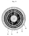
- Fig. 1 shows one example of a power cable having armoring wires (steel wires).
- the power cable shown in Fig. 1 includes, from its center to its outside, a conductor 10, an insulating layer 20 composed of carbon paper and insulating paper, a sheath 30 formed on an outside of the insulating layer 20, at least one steel strip layer 40, armoring wires 50 mainly composed of galvanized steel material, and a polypropylene yarn asphalt layer 60, which are arranged in order.
- This cable is generally manufactured in a unit length of 2 km or less, and in an installation region, ends of cables of unit length are connected using a junction box. In other case, if a middle portion of the cable needs to be repaired after installation, the corresponding portion of the cable is cut and then connected later using a junction box.
- threading works should be conducted for several tens of armoring wires one by one at the construction site, which is very cumbersome and consumes a lot of time.
- inferior threads may be formed frequently.
- any inferior thread is formed, there is no way to recover the armoring wire without cutting off the inferior portion.
- one armoring wire is cut to a certain length, all of the other armoring wires should be cut to match their lengths.
- an extra armoring wire having a length as long as the cut-off inferior portion should be welded to the above armoring wire to give its original length, and then the threading work should be conducted again.
- This disclosure is directed to providing a device for connecting armoring wires of a cable, which allows rapid and easy connection of ends of armoring wires at both sides in a cable connection portion.
- a device for connecting armoring wires of a cable wherein the device includes a hollow cylindrical connection unit 200 through which the cable is capable of passing, wherein a plurality of insert grooves 210 extending from end surfaces of the cylindrical connection unit 200 in a length direction are formed in an outer periphery of the cylindrical connection unit 200, and wherein the armoring wires 50 are inserted into the insert grooves 210 by inserting ends of the armoring wires 50 into the insert grooves 210 at both sides of the cylindrical connection unit 200 in a length direction or pressing outer peripheries of the armoring wires 50 into the insert grooves 210 in a radial direction.
- the insert grooves 210 of the cylindrical connection unit 200 may have a width narrower than an outer diameter d of the armoring wires 50.
- gaps between the armoring wires 50 and the insert grooves 210 may be welded.
- a device for connecting armoring wires of a cable comprising a hollow cylindrical connection unit 300 through which the cable is capable of passing, and wherein a plurality of insert holes 310 are formed in the cylindrical connection unit 300 along a length direction from end surfaces thereof at both sides such that the armoring wires 50 are inserted into the insert holes 310 at both sides, respectively.
- gaps between the armoring wires 50 and the insert holes 310 may be welded.
- a cylindrical connection unit prepared in a factory in advance may be used, so there is no need to make a separate connecting device at a construction site.
- armoring wires may be completely connected by simply inserting the armoring wire into an insert groove of the connecting device or inserting and welding the armoring wire, there is no need of separate additional works such as threading works, and inferiority does not occur at the connection portion.
- Fig. 2 is a perspective view showing a device for connecting armoring wires according to one embodiment disclosed herein, and Figs. 3 and 4 are respectively a sectional view and a front view showing the device of Fig. 2 .
- a device 100a for connecting armoring wires includes a plurality of insert grooves 210 formed in an outer periphery of a hollow cylindrical connection unit 200 and extending from both ends in a length direction.
- An armoring wire 50 of a cable may be inserted into the insert grooves 210 at both sides.
- the cylindrical connection unit 200 has an inner diameter D greater than an outer diameter of a junction box, which will be explained later, so that the cylindrical connection unit 200 may enclose the junction box.
- the insert groove 210 is formed by perforating an outer periphery of the cylindrical connection unit 200 inwards into a predetermined depth, and the insert groove 210 has a width w, which is narrower than the outer diameter d of the armoring wire 50 (see Fig. 4 ).
- the end of the armoring wire 50 may be inserted into the insert groove 210 from an end surface of the cylindrical connection unit 200.
- an outer periphery of the armoring wire 50 may be overlapped with an upper portion of the insert groove 210, and then the armoring wire 50 may be inserted by pressing it into the cylindrical connection unit 200 in a radial direction such that the armoring wire 50 may be inserted into the insert groove 210. If the armoring wire 50 is inserted or pressed into the insert groove 210, the armoring wire 50 is not separated from the insert groove 210 since the width w of the insert groove 210 is narrower than the diameter d of the armoring wire 50.
- a front end of the armoring wire 50 is welded to the cylindrical connection unit 200 (see Figs. 2 and 3 ), or along with or apart from this process, the gap between the outer periphery of the armoring wire 50 and the insert groove 210 is welded and fixed along a length direction of the insert groove 210 (see Figs. 2 and 4 ).
- Fig. 5 shows that the armoring wire 50 is connected at a cable connection portion by using the above connecting device 100a.
- one end of one cable 2a is firstly inserted into the cylindrical connection unit 200.
- both cables 2a, 2b are connected using a junction box 90.
- Outer periphery of the junction box 90 is generally coated with polypropylene yarn asphalt.
- the cylindrical connection unit 200 located at the outer periphery of one cable 2a is moved to be positioned at the outer periphery of the junction box 90 as shown in Fig. 5 . Since the inner diameter D of the cylindrical connection unit 200 is greater than the outer diameter of the junction box 90, the cylindrical connection unit 200 encloses the junction box.
- the armoring wires 50 at both sides are inserted or pressed into the insert grooves 210 at both sides of the cylindrical connection unit 200, and then the armoring wires 50 are welded and fixed thereto.
- outer portions of the cylindrical connection unit 200 and the armoring wires 50, exposed outward, are coated with polypropylene yarn asphalt 60 for sealing.
- the armoring wires 50 are completely connected by simply inserting, or pressing into the insert grooves 210 of the connecting device 100a, there is no need of additional works, for example screw works, at a construction site, and also there occurs no inferiority in the connection portion.
- Fig. 6 is a perspective view showing a device for connecting armoring wires according to another embodiment
- Figs. 7 and 8 are respectively a sectional view and a front view showing the device of Fig. 6
- Fig. 9 shows another example of the insert hole of Fig. 7 .
- the armoring wire connecting device 100b has a plurality of insert holes 310 perforated in a cylindrical connection unit 300 and extending in a length direction from both end surfaces thereof. Armoring wires 50 of cables may be inserted into the insert holes 310 at both sides, respectively.
- the cylindrical connection unit 300 has an inner diameter D greater than an outer diameter of a junction box so that the cylindrical connection unit 300 may be easily located at an outside of the junction box.
- a welding material 320 such as a tin-lead alloy is put into the insert holes 310 of the cylindrical connection unit 300 in advance, and the armoring wires 50 are inserted into the insert holes 310 and then the armoring wires 50 and the insert holes 310 are heated such that the welding material 320 is melted and then hardened (see Figs. 7 and 9 ).
- the insert holes may be tapered insert holes 310a whose diameter increases inwards as shown in Fig. 9 .
- the armoring wires may be restored by inserting the armoring wires into a cylindrical connection unit, prepared in advance in a factory, and then simply welding them without any cumbersome additional works for processing threads to the armoring wires at a construction site.
- the armoring wire connecting device disclosed herein is used as an intermediate connection unit of power cables used as submarine cables or optical fiber composite overhead ground wires (OPGW), as well as power cables or communications cables used on land, the armoring wires may be easily and rapidly connected at a construction site, and inferiority at the connection portion is also prevented.
- OPGW optical fiber composite overhead ground wires
Landscapes
- Cable Accessories (AREA)
- Processing Of Terminals (AREA)
- Suspension Of Electric Lines Or Cables (AREA)
Abstract
Description
- This disclosure relates to a device for connecting armoring wires of a cable, and more particularly, to a device for connecting armoring wires of a cable, which allows rapid and easy connection of armoring wires at a connecting portion of a power or communications cable.
- In case of power cables frequently used as submarine cables or optical fiber composite overhead ground wires (OPGW), as well as power cables or communications cables used on land, armoring wires are wound around an outer periphery of the cable to give strength and tensile force to the cable, as disclosed in Korean Laid-open Patent Publication No.
10-2004-0084291 10-0533219 20-036686 -
Fig. 1 shows one example of a power cable having armoring wires (steel wires). - The power cable shown in
Fig. 1 , includes, from its center to its outside, aconductor 10, aninsulating layer 20 composed of carbon paper and insulating paper, asheath 30 formed on an outside of the insulatinglayer 20, at least onesteel strip layer 40,armoring wires 50 mainly composed of galvanized steel material, and a polypropyleneyarn asphalt layer 60, which are arranged in order. - This cable is generally manufactured in a unit length of 2 km or less, and in an installation region, ends of cables of unit length are connected using a junction box. In other case, if a middle portion of the cable needs to be repaired after installation, the corresponding portion of the cable is cut and then connected later using a junction box.
- When cables are connected through a junction box as mentioned above, the cut armoring wires should also be connected and recovered.
- Until now, in order to recover (or, connect) armoring wires, screw portions respectively having right-hand and left-hand threads were formed at one end of both
armoring wires 50 by using threading dies, and turnbuckle-type sleeves were screwed to the screw portions of the armoring wires and then connected. - Thus, in the above technique, threading works should be conducted for several tens of armoring wires one by one at the construction site, which is very cumbersome and consumes a lot of time. In particular, if the dies are not accurately handled during the threading work, inferior threads may be formed frequently. Also, if any inferior thread is formed, there is no way to recover the armoring wire without cutting off the inferior portion. In addition, if one armoring wire is cut to a certain length, all of the other armoring wires should be cut to match their lengths. In other case, an extra armoring wire having a length as long as the cut-off inferior portion should be welded to the above armoring wire to give its original length, and then the threading work should be conducted again.
- This disclosure is directed to providing a device for connecting armoring wires of a cable, which allows rapid and easy connection of ends of armoring wires at both sides in a cable connection portion.
- In one aspect, there is provided a device for connecting armoring wires of a cable, wherein the device includes a hollow
cylindrical connection unit 200 through which the cable is capable of passing, wherein a plurality ofinsert grooves 210 extending from end surfaces of thecylindrical connection unit 200 in a length direction are formed in an outer periphery of thecylindrical connection unit 200, and wherein thearmoring wires 50 are inserted into theinsert grooves 210 by inserting ends of thearmoring wires 50 into theinsert grooves 210 at both sides of thecylindrical connection unit 200 in a length direction or pressing outer peripheries of thearmoring wires 50 into theinsert grooves 210 in a radial direction. - The
insert grooves 210 of thecylindrical connection unit 200 may have a width narrower than an outer diameter d of thearmoring wires 50. - After the
armoring wires 50 are inserted into theinsert grooves 210, gaps between thearmoring wires 50 and theinsert grooves 210 may be welded. - In another aspect, there is provided a device for connecting armoring wires of a cable, wherein the device comprises a hollow
cylindrical connection unit 300 through which the cable is capable of passing, and wherein a plurality ofinsert holes 310 are formed in thecylindrical connection unit 300 along a length direction from end surfaces thereof at both sides such that thearmoring wires 50 are inserted into theinsert holes 310 at both sides, respectively. - After the
armoring wires 50 are inserted into theinsert holes 310, gaps between thearmoring wires 50 and theinsert holes 310 may be welded. - Using the device for connecting armoring wires disclosed herein, when armoring wires are connected and restored in a cable connection portion, a cylindrical connection unit prepared in a factory in advance may be used, so there is no need to make a separate connecting device at a construction site.
- In addition, since armoring wires may be completely connected by simply inserting the armoring wire into an insert groove of the connecting device or inserting and welding the armoring wire, there is no need of separate additional works such as threading works, and inferiority does not occur at the connection portion.
- The above and other aspects, features and advantages of the disclosed exemplary embodiments will be more apparent from the following detailed description taken in conjunction with the accompanying drawings in which:
-
Fig. 1 is a sectional view showing a general cable; -
Fig. 2 is a perspective view showing a device for connecting armoring wires according to one embodiment disclosed herein; -
Fig. 3 is a sectional view showing the device ofFig. 2 ; -
Fig. 4 is a front view showing the device ofFig. 2 ; -
Fig. 5 shows that armoring wires of a cable connection portion are connected to the connecting device according to one embodiment disclosed herein; -
Fig. 6 is a perspective view showing a device for connecting armoring wires according to another embodiment disclosed herein; -
Fig. 7 is a sectional view showing the device ofFig. 6 ; -
Fig. 8 is a front view showing the device ofFig. 6 ; and -
Fig. 9 shows another example of the insert hole ofFig. 7 . - Exemplary embodiments now will be described more fully hereinafter with reference to the accompanying drawings, in which exemplary embodiments are shown. This disclosure may, however, be embodied in many different forms and should not be construed as limited to the exemplary embodiments set forth therein. Rather, these exemplary embodiments are provided so that this disclosure will be thorough and complete, and will fully convey the scope of this disclosure to those skilled in the art. In the description, details of well-known features and techniques may be omitted to avoid unnecessarily obscuring the presented embodiments.
- The terminology used herein is for the purpose of describing particular embodiments only and is not intended to be limiting of this disclosure. As used herein, the singular forms "a", "an" and "the" are intended to include the plural forms as well, unless the context clearly indicates otherwise. Furthermore, the use of the terms a, an, etc. does not denote a limitation of quantity, but rather denotes the presence of at least one of the referenced item. The use of the terms "first", "second", and the like does not imply any particular order, but they are included to identify individual elements. Moreover, the use of the terms first, second, etc. does not denote any order or importance, but rather the terms first, second, etc. are used to distinguish one element from another. It will be further understood that the terms "comprises" and/or "comprising", or "includes" and/or "including" when used in this specification, specify the presence of stated features, regions, integers, steps, operations, elements, and/or components, but do not preclude the presence or addition of one or more other features, regions, integers, steps, operations, elements, components, and/or groups thereof.
- Unless otherwise defined, all terms (including technical and scientific terms) used herein have the same meaning as commonly understood by one of ordinary skill in the art. It will be further understood that terms, such as those defined in commonly used dictionaries, should be interpreted as having a meaning that is consistent with their meaning in the context of the relevant art and the present disclosure, and will not be interpreted in an idealized or overly formal sense unless expressly so defined herein.
- In the drawings, like reference numerals in the drawings denote like elements. The shape, size and regions, and the like, of the drawing may be exaggerated for clarity.
-
Fig. 2 is a perspective view showing a device for connecting armoring wires according to one embodiment disclosed herein, andFigs. 3 and4 are respectively a sectional view and a front view showing the device ofFig. 2 . - As shown in
Figs. 2 to 4 , adevice 100a for connecting armoring wires according to one embodiment disclosed herein includes a plurality ofinsert grooves 210 formed in an outer periphery of a hollowcylindrical connection unit 200 and extending from both ends in a length direction. Anarmoring wire 50 of a cable may be inserted into theinsert grooves 210 at both sides. - The
cylindrical connection unit 200 has an inner diameter D greater than an outer diameter of a junction box, which will be explained later, so that thecylindrical connection unit 200 may enclose the junction box. - The
insert groove 210 is formed by perforating an outer periphery of thecylindrical connection unit 200 inwards into a predetermined depth, and theinsert groove 210 has a width w, which is narrower than the outer diameter d of the armoring wire 50 (seeFig. 4 ). - Thus, as shown in a right region of
Fig. 3 , the end of thearmoring wire 50 may be inserted into theinsert groove 210 from an end surface of thecylindrical connection unit 200. - Alternatively, as shown in a left region of
Fig. 3 , an outer periphery of thearmoring wire 50 may be overlapped with an upper portion of theinsert groove 210, and then thearmoring wire 50 may be inserted by pressing it into thecylindrical connection unit 200 in a radial direction such that thearmoring wire 50 may be inserted into theinsert groove 210. If thearmoring wire 50 is inserted or pressed into theinsert groove 210, thearmoring wire 50 is not separated from theinsert groove 210 since the width w of theinsert groove 210 is narrower than the diameter d of thearmoring wire 50. - After the
armoring wire 50 is inserted or pressed into theinsert groove 210 of thecylindrical connection unit 200, a front end of thearmoring wire 50 is welded to the cylindrical connection unit 200 (seeFigs. 2 and3 ), or along with or apart from this process, the gap between the outer periphery of thearmoring wire 50 and theinsert groove 210 is welded and fixed along a length direction of the insert groove 210 (seeFigs. 2 and4 ). -
Fig. 5 shows that thearmoring wire 50 is connected at a cable connection portion by using the above connectingdevice 100a. - In order to install the
cylindrical connection unit 200 disclosed herein to a cable connection portion, one end of onecable 2a is firstly inserted into thecylindrical connection unit 200. In this state, bothcables junction box 90. Outer periphery of thejunction box 90 is generally coated with polypropylene yarn asphalt. - If the
junction box 90 is completely installed as mentioned above, thecylindrical connection unit 200 located at the outer periphery of onecable 2a is moved to be positioned at the outer periphery of thejunction box 90 as shown inFig. 5 . Since the inner diameter D of thecylindrical connection unit 200 is greater than the outer diameter of thejunction box 90, thecylindrical connection unit 200 encloses the junction box. - Then, the
armoring wires 50 at both sides are inserted or pressed into theinsert grooves 210 at both sides of thecylindrical connection unit 200, and then thearmoring wires 50 are welded and fixed thereto. - After the
armoring wires 50 are connected as mentioned above, outer portions of thecylindrical connection unit 200 and thearmoring wires 50, exposed outward, are coated withpolypropylene yarn asphalt 60 for sealing. - When the
armoring wires 50 are connected and restored at the cable connection portion as mentioned above, it is possible to use thecylindrical connection unit 200 prepared in advance in a factory. Thus, there is no need to make a connecting device at a construction site. - In addition, since the
armoring wires 50 are completely connected by simply inserting, or pressing into theinsert grooves 210 of the connectingdevice 100a, there is no need of additional works, for example screw works, at a construction site, and also there occurs no inferiority in the connection portion. -
Fig. 6 is a perspective view showing a device for connecting armoring wires according to another embodiment, andFigs. 7 and8 are respectively a sectional view and a front view showing the device ofFig. 6 . And,Fig. 9 shows another example of the insert hole ofFig. 7 . - As shown in
Figs. 6 to 8 , the armoringwire connecting device 100b according to another embodiment has a plurality of insert holes 310 perforated in acylindrical connection unit 300 and extending in a length direction from both end surfaces thereof. Armoringwires 50 of cables may be inserted into the insert holes 310 at both sides, respectively. - The
cylindrical connection unit 300 has an inner diameter D greater than an outer diameter of a junction box so that thecylindrical connection unit 300 may be easily located at an outside of the junction box. - After the
armoring wires 50 are inserted into the insert holes 310 of thecylindrical connection unit 300 according to the present invention, gaps between thearmoring wires 50 and the insert holes 310 are welded for fixture (seeFigs. 7 and8 ). - Alternatively, it is also possible that a
welding material 320 such as a tin-lead alloy is put into the insert holes 310 of thecylindrical connection unit 300 in advance, and thearmoring wires 50 are inserted into the insert holes 310 and then thearmoring wires 50 and the insert holes 310 are heated such that thewelding material 320 is melted and then hardened (seeFigs. 7 and9 ). - In case the
welding material 320 is put into the insert holes in advance and then melted for adhesion, the insert holes may be taperedinsert holes 310a whose diameter increases inwards as shown inFig. 9 . - As described above, if the device for connecting armoring wires of a cable disclosed above is used, the armoring wires may be restored by inserting the armoring wires into a cylindrical connection unit, prepared in advance in a factory, and then simply welding them without any cumbersome additional works for processing threads to the armoring wires at a construction site.
- Thus, if the armoring wire connecting device disclosed herein is used as an intermediate connection unit of power cables used as submarine cables or optical fiber composite overhead ground wires (OPGW), as well as power cables or communications cables used on land, the armoring wires may be easily and rapidly connected at a construction site, and inferiority at the connection portion is also prevented.
- While the exemplary embodiments have been shown and described, it will be understood by those skilled in the art that various changes in form and details may be made thereto without departing from the spirit and scope of this disclosure as defined by the appended claims.
- In addition, many modifications can be made to adapt a particular situation or material to the teachings of this disclosure without departing from the essential scope thereof. Therefore, it is intended that this disclosure not be limited to the particular exemplary embodiments disclosed as the best mode contemplated for carrying out this disclosure, but that this disclosure will include all embodiments falling within the scope of the appended claims.
Claims (5)
- A device for connecting armoring wires of a cable, which is used for connecting and restoring the armoring wires (50),
wherein the device comprises a hollow cylindrical connection unit (200) through which the cable is capable of passing,
wherein a plurality of insert grooves (210) extending from end surfaces of the cylindrical connection unit (200) in a length direction are formed in an outer periphery of the cylindrical connection unit (200), and
wherein the armoring wires (50) are inserted into the insert grooves (210) by inserting ends of the armoring wires (50) into the insert grooves (210) at both sides of the cylindrical connection unit (200) in a length direction or pressing outer peripheries of the armoring wires (50) into the insert grooves (210) in a radial direction. - The device for connecting armoring wires of a cable according to claim 1, wherein the insert grooves (210) of the cylindrical connection unit (200) have a width narrower than an outer diameter of the armoring wires (50).
- The device for connecting armoring wires of a cable according to claim 1, wherein, after the armoring wires (50) are inserted into the insert grooves (210), gaps between the armoring wires (50) and the insert grooves (210) are welded.
- A device for connecting armoring wires of a cable, which is used for connecting and restoring the armoring wires (50),
wherein the device comprises a hollow cylindrical connection unit (300) through which the cable is capable of passing, and
wherein a plurality of insert holes (310) are formed in the cylindrical connection unit (300) along a length direction from end surfaces thereof at both sides such that the armoring wires (50) are inserted into the insert holes (310) at both sides, respectively. - The device for connecting armoring wires of a cable according to claim 4, wherein, after the armoring wires (50) are inserted into the insert holes (310), gaps between the armoring wires (50) and the insert holes (310) are welded.
Applications Claiming Priority (1)
| Application Number | Priority Date | Filing Date | Title |
|---|---|---|---|
| KR1020090007948A KR20100088831A (en) | 2009-02-02 | 2009-02-02 | Device for connecting the outer wires of the cable |
Publications (2)
| Publication Number | Publication Date |
|---|---|
| EP2214279A2 true EP2214279A2 (en) | 2010-08-04 |
| EP2214279A3 EP2214279A3 (en) | 2011-05-18 |
Family
ID=42236643
Family Applications (1)
| Application Number | Title | Priority Date | Filing Date |
|---|---|---|---|
| EP09012312A Withdrawn EP2214279A3 (en) | 2009-02-02 | 2009-09-29 | Device for connecting armoring wires of cable |
Country Status (3)
| Country | Link |
|---|---|
| EP (1) | EP2214279A3 (en) |
| JP (1) | JP2010178613A (en) |
| KR (1) | KR20100088831A (en) |
Cited By (6)
| Publication number | Priority date | Publication date | Assignee | Title |
|---|---|---|---|---|
| WO2016131965A1 (en) * | 2015-02-19 | 2016-08-25 | Abb Technology Ltd | Welding sleeve for armoured cables |
| EP3108552A1 (en) * | 2014-02-19 | 2016-12-28 | ABB Schweiz AG | Method of assembling a hang-off device with a cable, a hang-off device and a hang-off arrangement |
| CN112366617A (en) * | 2020-11-26 | 2021-02-12 | 上海建安化工设计有限公司 | Load-bearing cable armor recovery device |
| CN113437704A (en) * | 2021-06-15 | 2021-09-24 | 南海海缆有限公司 | Submarine cable underwater repairing method and submarine cable |
| US11309102B2 (en) * | 2016-08-18 | 2022-04-19 | Ls Cable & System Ltd. | Power cable |
| US12108558B2 (en) * | 2022-10-25 | 2024-10-01 | Hewlett Packard Enterprise Development Lp | Crosstalk regulator for cables |
Families Citing this family (4)
| Publication number | Priority date | Publication date | Assignee | Title |
|---|---|---|---|---|
| JP2013150370A (en) * | 2012-01-17 | 2013-08-01 | Viscas Corp | Armoring wire connection fitting of cable and armoring wire connection method using the same and connection |
| JP2013162634A (en) * | 2012-02-06 | 2013-08-19 | Viscas Corp | Exterior iron wire connection metal fitting, and connection method and connection part for exterior iron wire using the same |
| KR102710133B1 (en) * | 2019-02-18 | 2024-09-25 | 엘에스전선 주식회사 | Bimetallic Armour Wires And Submarine Cable Having The Same |
| US20260121393A1 (en) * | 2024-10-29 | 2026-04-30 | Alkhorayef Petroleum Company | Spoolable splice for use in electrical submersible pump system |
Citations (1)
| Publication number | Priority date | Publication date | Assignee | Title |
|---|---|---|---|---|
| KR100533219B1 (en) | 2003-07-08 | 2005-12-02 | 성동현 | Optical fiber joint box for submarine telecommunication cable |
Family Cites Families (6)
| Publication number | Priority date | Publication date | Assignee | Title |
|---|---|---|---|---|
| JPS4846891A (en) * | 1971-10-18 | 1973-07-04 | ||
| JPS518497U (en) * | 1974-07-05 | 1976-01-22 | ||
| JPS5120590A (en) * | 1974-08-13 | 1976-02-18 | Hitachi Cable | TETSUSENGAISOKEEBURUSETSUZOKUBU |
| JPS52114992A (en) * | 1976-03-23 | 1977-09-27 | Hitachi Cable Ltd | Connecting method of metal wire clad cable |
| JPS52106595U (en) * | 1977-02-08 | 1977-08-13 | ||
| JPH0819230A (en) * | 1994-06-24 | 1996-01-19 | Hitachi Koki Co Ltd | High frequency motor |
-
2009
- 2009-02-02 KR KR1020090007948A patent/KR20100088831A/en not_active Ceased
- 2009-09-29 EP EP09012312A patent/EP2214279A3/en not_active Withdrawn
- 2009-10-19 JP JP2009240138A patent/JP2010178613A/en active Pending
Patent Citations (1)
| Publication number | Priority date | Publication date | Assignee | Title |
|---|---|---|---|---|
| KR100533219B1 (en) | 2003-07-08 | 2005-12-02 | 성동현 | Optical fiber joint box for submarine telecommunication cable |
Cited By (8)
| Publication number | Priority date | Publication date | Assignee | Title |
|---|---|---|---|---|
| EP3108552A1 (en) * | 2014-02-19 | 2016-12-28 | ABB Schweiz AG | Method of assembling a hang-off device with a cable, a hang-off device and a hang-off arrangement |
| WO2016131965A1 (en) * | 2015-02-19 | 2016-08-25 | Abb Technology Ltd | Welding sleeve for armoured cables |
| US10224704B2 (en) | 2015-02-19 | 2019-03-05 | Nkt Hv Cables Gmbh | Welding sleeve for armoured cables |
| US11309102B2 (en) * | 2016-08-18 | 2022-04-19 | Ls Cable & System Ltd. | Power cable |
| CN112366617A (en) * | 2020-11-26 | 2021-02-12 | 上海建安化工设计有限公司 | Load-bearing cable armor recovery device |
| CN113437704A (en) * | 2021-06-15 | 2021-09-24 | 南海海缆有限公司 | Submarine cable underwater repairing method and submarine cable |
| CN113437704B (en) * | 2021-06-15 | 2022-12-09 | 南海海缆有限公司 | Submarine cable underwater repairing method and submarine cable |
| US12108558B2 (en) * | 2022-10-25 | 2024-10-01 | Hewlett Packard Enterprise Development Lp | Crosstalk regulator for cables |
Also Published As
| Publication number | Publication date |
|---|---|
| EP2214279A3 (en) | 2011-05-18 |
| KR20100088831A (en) | 2010-08-11 |
| JP2010178613A (en) | 2010-08-12 |
Similar Documents
| Publication | Publication Date | Title |
|---|---|---|
| JP2010178613A (en) | Jointing apparatus of armoring iron wire of cable | |
| US8558427B2 (en) | Insulation assembly for electric machine | |
| US6545222B2 (en) | Cable, and method for removing sheath at intermediate part of cable | |
| US9905942B2 (en) | Assemblies and methods for electrical splice connections of cables | |
| AU2009342250B2 (en) | Optical cable with improved strippability | |
| CA2211178C (en) | Support core ribbon for cold-shrink tube | |
| FI79426B (en) | CABLE CONNECTION PROTECTION | |
| JP4224092B2 (en) | Optical fiber cable and its branching method | |
| JP5846758B2 (en) | Optical fiber cable and optical fiber cable branching method | |
| WO2009069941A2 (en) | Pipeline detection cable and connection method of pipeline detection cables | |
| EP1928067B1 (en) | Method of constructing a normal joint structure of a superconducting cable | |
| EP2315217B1 (en) | Set for producing an electric installation | |
| JP2015015832A (en) | Exterior protective structure of wire harness | |
| US10957996B2 (en) | Connector made of an electrically insulating material to electrically connect a main conductor and a secondary conductor | |
| JP5863268B2 (en) | Optical fiber cable and optical fiber cable branching method | |
| JP2007026802A (en) | Electric wire with ground wire | |
| DE102015117020B4 (en) | Method for producing a line seal of a line harness and method for producing a sealed line connection | |
| KR100639313B1 (en) | Insulation cover for high voltage branch | |
| WO2021148627A1 (en) | Cable for a system for conducting and distributing electrical energy and for providing a fast data-conducting communication link | |
| JP2009217195A (en) | Optical fiber cable | |
| KR101940867B1 (en) | Cable linking method | |
| KR200329939Y1 (en) | Sealing cap for communication pipe | |
| JP6736879B2 (en) | Optical fiber cable identification system and optical fiber cable identification method | |
| KR100533219B1 (en) | Optical fiber joint box for submarine telecommunication cable | |
| US20220367088A1 (en) | Branched wire harness manufacturing method |
Legal Events
| Date | Code | Title | Description |
|---|---|---|---|
| PUAI | Public reference made under article 153(3) epc to a published international application that has entered the european phase |
Free format text: ORIGINAL CODE: 0009012 |
|
| AK | Designated contracting states |
Kind code of ref document: A2 Designated state(s): AT BE BG CH CY CZ DE DK EE ES FI FR GB GR HR HU IE IS IT LI LT LU LV MC MK MT NL NO PL PT RO SE SI SK SM TR |
|
| AX | Request for extension of the european patent |
Extension state: AL BA RS |
|
| PUAL | Search report despatched |
Free format text: ORIGINAL CODE: 0009013 |
|
| AK | Designated contracting states |
Kind code of ref document: A3 Designated state(s): AT BE BG CH CY CZ DE DK EE ES FI FR GB GR HR HU IE IS IT LI LT LU LV MC MK MT NL NO PL PT RO SE SI SK SM TR |
|
| AX | Request for extension of the european patent |
Extension state: AL BA RS |
|
| STAA | Information on the status of an ep patent application or granted ep patent |
Free format text: STATUS: THE APPLICATION IS DEEMED TO BE WITHDRAWN |
|
| 18D | Application deemed to be withdrawn |
Effective date: 20111119 |