EP2214062A1 - Electrophotographic member comprised of a polymer matrix with the addition of graphene-containing particles - Google Patents
Electrophotographic member comprised of a polymer matrix with the addition of graphene-containing particles Download PDFInfo
- Publication number
- EP2214062A1 EP2214062A1 EP10151217A EP10151217A EP2214062A1 EP 2214062 A1 EP2214062 A1 EP 2214062A1 EP 10151217 A EP10151217 A EP 10151217A EP 10151217 A EP10151217 A EP 10151217A EP 2214062 A1 EP2214062 A1 EP 2214062A1
- Authority
- EP
- European Patent Office
- Prior art keywords
- graphene
- polymer
- containing particles
- polymer matrix
- substrate
- Prior art date
- Legal status (The legal status is an assumption and is not a legal conclusion. Google has not performed a legal analysis and makes no representation as to the accuracy of the status listed.)
- Granted
Links
- OKTJSMMVPCPJKN-UHFFFAOYSA-N Carbon Chemical compound [C] OKTJSMMVPCPJKN-UHFFFAOYSA-N 0.000 title claims abstract description 102
- 229910021389 graphene Inorganic materials 0.000 title claims abstract description 75
- 229920000642 polymer Polymers 0.000 title claims abstract description 54
- 239000002245 particle Substances 0.000 title claims abstract description 50
- 239000011159 matrix material Substances 0.000 title claims abstract description 28
- 239000000203 mixture Substances 0.000 claims abstract description 47
- 239000000758 substrate Substances 0.000 claims abstract description 34
- 238000000034 method Methods 0.000 claims abstract description 26
- 239000006185 dispersion Substances 0.000 claims abstract description 24
- -1 thermoelastomers Polymers 0.000 claims description 20
- 239000000945 filler Substances 0.000 claims description 19
- BQCIDUSAKPWEOX-UHFFFAOYSA-N 1,1-Difluoroethene Chemical compound FC(F)=C BQCIDUSAKPWEOX-UHFFFAOYSA-N 0.000 claims description 14
- BFKJFAAPBSQJPD-UHFFFAOYSA-N tetrafluoroethene Chemical group FC(F)=C(F)F BFKJFAAPBSQJPD-UHFFFAOYSA-N 0.000 claims description 14
- HCDGVLDPFQMKDK-UHFFFAOYSA-N hexafluoropropylene Chemical group FC(F)=C(F)C(F)(F)F HCDGVLDPFQMKDK-UHFFFAOYSA-N 0.000 claims description 12
- 239000002904 solvent Substances 0.000 claims description 11
- 229920001973 fluoroelastomer Polymers 0.000 claims description 10
- 229920001577 copolymer Polymers 0.000 claims description 9
- 229920002313 fluoropolymer Polymers 0.000 claims description 9
- FJKIXWOMBXYWOQ-UHFFFAOYSA-N ethenoxyethane Chemical compound CCOC=C FJKIXWOMBXYWOQ-UHFFFAOYSA-N 0.000 claims description 8
- XMWRBQBLMFGWIX-UHFFFAOYSA-N C60 fullerene Chemical compound C12=C3C(C4=C56)=C7C8=C5C5=C9C%10=C6C6=C4C1=C1C4=C6C6=C%10C%10=C9C9=C%11C5=C8C5=C8C7=C3C3=C7C2=C1C1=C2C4=C6C4=C%10C6=C9C9=C%11C5=C5C8=C3C3=C7C1=C1C2=C4C6=C2C9=C5C3=C12 XMWRBQBLMFGWIX-UHFFFAOYSA-N 0.000 claims description 6
- 239000002048 multi walled nanotube Substances 0.000 claims description 6
- 239000002121 nanofiber Substances 0.000 claims description 6
- 239000002109 single walled nanotube Substances 0.000 claims description 6
- 239000003795 chemical substances by application Substances 0.000 claims description 5
- 239000004811 fluoropolymer Substances 0.000 claims description 5
- 239000002071 nanotube Substances 0.000 claims description 5
- 229920001343 polytetrafluoroethylene Polymers 0.000 claims description 5
- 239000004810 polytetrafluoroethylene Substances 0.000 claims description 5
- KHXKESCWFMPTFT-UHFFFAOYSA-N 1,1,1,2,2,3,3-heptafluoro-3-(1,2,2-trifluoroethenoxy)propane Chemical compound FC(F)=C(F)OC(F)(F)C(F)(F)C(F)(F)F KHXKESCWFMPTFT-UHFFFAOYSA-N 0.000 claims description 4
- BLTXWCKMNMYXEA-UHFFFAOYSA-N 1,1,2-trifluoro-2-(trifluoromethoxy)ethene Chemical compound FC(F)=C(F)OC(F)(F)F BLTXWCKMNMYXEA-UHFFFAOYSA-N 0.000 claims description 4
- 229910052751 metal Inorganic materials 0.000 claims description 4
- 239000002184 metal Substances 0.000 claims description 4
- 229920002379 silicone rubber Polymers 0.000 claims description 4
- 229930185605 Bisphenol Natural products 0.000 claims description 3
- 101710158075 Bucky ball Proteins 0.000 claims description 3
- 150000001875 compounds Chemical class 0.000 claims description 3
- 229910044991 metal oxide Inorganic materials 0.000 claims description 3
- 150000004706 metal oxides Chemical class 0.000 claims description 3
- 150000002739 metals Chemical class 0.000 claims description 3
- 239000002061 nanopillar Substances 0.000 claims description 3
- 239000002073 nanorod Substances 0.000 claims description 3
- 239000002070 nanowire Substances 0.000 claims description 3
- 229920005989 resin Polymers 0.000 claims description 3
- 239000011347 resin Substances 0.000 claims description 3
- 238000004132 cross linking Methods 0.000 claims description 2
- 239000003431 cross linking reagent Substances 0.000 claims description 2
- FZHAPNGMFPVSLP-UHFFFAOYSA-N silanamine Chemical compound [SiH3]N FZHAPNGMFPVSLP-UHFFFAOYSA-N 0.000 claims description 2
- 239000000835 fiber Substances 0.000 claims 2
- 239000000463 material Substances 0.000 abstract description 30
- 239000010410 layer Substances 0.000 description 25
- 229910002804 graphite Inorganic materials 0.000 description 11
- 239000010439 graphite Substances 0.000 description 11
- 229910052799 carbon Inorganic materials 0.000 description 10
- 229920003249 vinylidene fluoride hexafluoropropylene elastomer Polymers 0.000 description 8
- ZWEHNKRNPOVVGH-UHFFFAOYSA-N 2-Butanone Chemical compound CCC(C)=O ZWEHNKRNPOVVGH-UHFFFAOYSA-N 0.000 description 6
- 229920002449 FKM Polymers 0.000 description 6
- ZMXDDKWLCZADIW-UHFFFAOYSA-N N,N-Dimethylformamide Chemical compound CN(C)C=O ZMXDDKWLCZADIW-UHFFFAOYSA-N 0.000 description 6
- RYGMFSIKBFXOCR-UHFFFAOYSA-N Copper Chemical compound [Cu] RYGMFSIKBFXOCR-UHFFFAOYSA-N 0.000 description 5
- 239000010949 copper Substances 0.000 description 5
- 229910052802 copper Inorganic materials 0.000 description 5
- 239000013078 crystal Substances 0.000 description 5
- WYURNTSHIVDZCO-UHFFFAOYSA-N tetrahydrofuran Substances C1CCOC1 WYURNTSHIVDZCO-UHFFFAOYSA-N 0.000 description 5
- IAZDPXIOMUYVGZ-UHFFFAOYSA-N Dimethylsulphoxide Chemical compound CS(C)=O IAZDPXIOMUYVGZ-UHFFFAOYSA-N 0.000 description 4
- SECXISVLQFMRJM-UHFFFAOYSA-N N-Methylpyrrolidone Chemical compound CN1CCCC1=O SECXISVLQFMRJM-UHFFFAOYSA-N 0.000 description 4
- PXHVJJICTQNCMI-UHFFFAOYSA-N Nickel Chemical compound [Ni] PXHVJJICTQNCMI-UHFFFAOYSA-N 0.000 description 4
- 229920006362 Teflon® Polymers 0.000 description 4
- 125000004432 carbon atom Chemical group C* 0.000 description 4
- CATSNJVOTSVZJV-UHFFFAOYSA-N heptan-2-one Chemical compound CCCCCC(C)=O CATSNJVOTSVZJV-UHFFFAOYSA-N 0.000 description 4
- CSCPPACGZOOCGX-UHFFFAOYSA-N Acetone Chemical compound CC(C)=O CSCPPACGZOOCGX-UHFFFAOYSA-N 0.000 description 3
- XEKOWRVHYACXOJ-UHFFFAOYSA-N Ethyl acetate Chemical compound CCOC(C)=O XEKOWRVHYACXOJ-UHFFFAOYSA-N 0.000 description 3
- 239000004812 Fluorinated ethylene propylene Substances 0.000 description 3
- OKKJLVBELUTLKV-UHFFFAOYSA-N Methanol Chemical compound OC OKKJLVBELUTLKV-UHFFFAOYSA-N 0.000 description 3
- 239000002041 carbon nanotube Substances 0.000 description 3
- 229910021393 carbon nanotube Inorganic materials 0.000 description 3
- 239000002131 composite material Substances 0.000 description 3
- 229920009441 perflouroethylene propylene Polymers 0.000 description 3
- 239000002356 single layer Substances 0.000 description 3
- 239000004971 Cross linker Substances 0.000 description 2
- LFQSCWFLJHTTHZ-UHFFFAOYSA-N Ethanol Chemical compound CCO LFQSCWFLJHTTHZ-UHFFFAOYSA-N 0.000 description 2
- NTIZESTWPVYFNL-UHFFFAOYSA-N Methyl isobutyl ketone Chemical compound CC(C)CC(C)=O NTIZESTWPVYFNL-UHFFFAOYSA-N 0.000 description 2
- UIHCLUNTQKBZGK-UHFFFAOYSA-N Methyl isobutyl ketone Natural products CCC(C)C(C)=O UIHCLUNTQKBZGK-UHFFFAOYSA-N 0.000 description 2
- BZLVMXJERCGZMT-UHFFFAOYSA-N Methyl tert-butyl ether Chemical compound COC(C)(C)C BZLVMXJERCGZMT-UHFFFAOYSA-N 0.000 description 2
- 229910052581 Si3N4 Inorganic materials 0.000 description 2
- BQCADISMDOOEFD-UHFFFAOYSA-N Silver Chemical compound [Ag] BQCADISMDOOEFD-UHFFFAOYSA-N 0.000 description 2
- GWEVSGVZZGPLCZ-UHFFFAOYSA-N Titan oxide Chemical compound O=[Ti]=O GWEVSGVZZGPLCZ-UHFFFAOYSA-N 0.000 description 2
- 238000013019 agitation Methods 0.000 description 2
- PNEYBMLMFCGWSK-UHFFFAOYSA-N aluminium oxide Inorganic materials [O-2].[O-2].[O-2].[Al+3].[Al+3] PNEYBMLMFCGWSK-UHFFFAOYSA-N 0.000 description 2
- 230000015572 biosynthetic process Effects 0.000 description 2
- 238000005229 chemical vapour deposition Methods 0.000 description 2
- PMHQVHHXPFUNSP-UHFFFAOYSA-M copper(1+);methylsulfanylmethane;bromide Chemical compound Br[Cu].CSC PMHQVHHXPFUNSP-UHFFFAOYSA-M 0.000 description 2
- 239000002346 layers by function Substances 0.000 description 2
- 229910052759 nickel Inorganic materials 0.000 description 2
- TWNQGVIAIRXVLR-UHFFFAOYSA-N oxo(oxoalumanyloxy)alumane Chemical compound O=[Al]O[Al]=O TWNQGVIAIRXVLR-UHFFFAOYSA-N 0.000 description 2
- 230000000704 physical effect Effects 0.000 description 2
- HBMJWWWQQXIZIP-UHFFFAOYSA-N silicon carbide Chemical compound [Si+]#[C-] HBMJWWWQQXIZIP-UHFFFAOYSA-N 0.000 description 2
- 229910010271 silicon carbide Inorganic materials 0.000 description 2
- HQVNEWCFYHHQES-UHFFFAOYSA-N silicon nitride Chemical compound N12[Si]34N5[Si]62N3[Si]51N64 HQVNEWCFYHHQES-UHFFFAOYSA-N 0.000 description 2
- 229910052709 silver Inorganic materials 0.000 description 2
- 239000004332 silver Substances 0.000 description 2
- 239000007787 solid Substances 0.000 description 2
- YLQBMQCUIZJEEH-UHFFFAOYSA-N tetrahydrofuran Natural products C=1C=COC=1 YLQBMQCUIZJEEH-UHFFFAOYSA-N 0.000 description 2
- OGIDPMRJRNCKJF-UHFFFAOYSA-N titanium oxide Inorganic materials [Ti]=O OGIDPMRJRNCKJF-UHFFFAOYSA-N 0.000 description 2
- XLYOFNOQVPJJNP-UHFFFAOYSA-N water Substances O XLYOFNOQVPJJNP-UHFFFAOYSA-N 0.000 description 2
- DKPFZGUDAPQIHT-UHFFFAOYSA-N Butyl acetate Natural products CCCCOC(C)=O DKPFZGUDAPQIHT-UHFFFAOYSA-N 0.000 description 1
- UGFAIRIUMAVXCW-UHFFFAOYSA-N Carbon monoxide Chemical compound [O+]#[C-] UGFAIRIUMAVXCW-UHFFFAOYSA-N 0.000 description 1
- 239000001825 Polyoxyethene (8) stearate Substances 0.000 description 1
- XUIMIQQOPSSXEZ-UHFFFAOYSA-N Silicon Chemical compound [Si] XUIMIQQOPSSXEZ-UHFFFAOYSA-N 0.000 description 1
- 239000004809 Teflon Substances 0.000 description 1
- 229920006172 Tetrafluoroethylene propylene Polymers 0.000 description 1
- 238000007239 Wittig reaction Methods 0.000 description 1
- 230000004075 alteration Effects 0.000 description 1
- 229910052782 aluminium Inorganic materials 0.000 description 1
- XAGFODPZIPBFFR-UHFFFAOYSA-N aluminium Chemical compound [Al] XAGFODPZIPBFFR-UHFFFAOYSA-N 0.000 description 1
- 125000004429 atom Chemical group 0.000 description 1
- 238000000498 ball milling Methods 0.000 description 1
- IISBACLAFKSPIT-UHFFFAOYSA-N bisphenol A Chemical compound C=1C=C(O)C=CC=1C(C)(C)C1=CC=C(O)C=C1 IISBACLAFKSPIT-UHFFFAOYSA-N 0.000 description 1
- 229910002091 carbon monoxide Inorganic materials 0.000 description 1
- 125000002915 carbonyl group Chemical group [*:2]C([*:1])=O 0.000 description 1
- 239000002800 charge carrier Substances 0.000 description 1
- 238000007385 chemical modification Methods 0.000 description 1
- 239000007810 chemical reaction solvent Substances 0.000 description 1
- 239000011248 coating agent Substances 0.000 description 1
- 238000000576 coating method Methods 0.000 description 1
- 229920001940 conductive polymer Polymers 0.000 description 1
- 125000004122 cyclic group Chemical group 0.000 description 1
- 230000007547 defect Effects 0.000 description 1
- 238000000151 deposition Methods 0.000 description 1
- 230000008021 deposition Effects 0.000 description 1
- 238000001035 drying Methods 0.000 description 1
- 238000010891 electric arc Methods 0.000 description 1
- 238000005516 engineering process Methods 0.000 description 1
- 235000019441 ethanol Nutrition 0.000 description 1
- 238000001125 extrusion Methods 0.000 description 1
- 239000004744 fabric Substances 0.000 description 1
- 239000012530 fluid Substances 0.000 description 1
- 239000012634 fragment Substances 0.000 description 1
- 229910003472 fullerene Inorganic materials 0.000 description 1
- 238000000227 grinding Methods 0.000 description 1
- FUZZWVXGSFPDMH-UHFFFAOYSA-N hexanoic acid Chemical compound CCCCCC(O)=O FUZZWVXGSFPDMH-UHFFFAOYSA-N 0.000 description 1
- 238000009396 hybridization Methods 0.000 description 1
- 239000012535 impurity Substances 0.000 description 1
- 238000002347 injection Methods 0.000 description 1
- 239000007924 injection Substances 0.000 description 1
- 239000011256 inorganic filler Substances 0.000 description 1
- 229910003475 inorganic filler Inorganic materials 0.000 description 1
- 238000000608 laser ablation Methods 0.000 description 1
- 238000010297 mechanical methods and process Methods 0.000 description 1
- 230000005226 mechanical processes and functions Effects 0.000 description 1
- 238000002156 mixing Methods 0.000 description 1
- 230000004048 modification Effects 0.000 description 1
- 238000012986 modification Methods 0.000 description 1
- 238000000465 moulding Methods 0.000 description 1
- 239000002798 polar solvent Substances 0.000 description 1
- 125000003367 polycyclic group Chemical group 0.000 description 1
- 238000007639 printing Methods 0.000 description 1
- 239000011541 reaction mixture Substances 0.000 description 1
- 239000010703 silicon Substances 0.000 description 1
- 229910052710 silicon Inorganic materials 0.000 description 1
- 239000004945 silicone rubber Substances 0.000 description 1
- 238000000527 sonication Methods 0.000 description 1
- 239000007921 spray Substances 0.000 description 1
- 238000003756 stirring Methods 0.000 description 1
- 239000000126 substance Substances 0.000 description 1
- 239000002344 surface layer Substances 0.000 description 1
- 239000000725 suspension Substances 0.000 description 1
- 238000003786 synthesis reaction Methods 0.000 description 1
- 229920001897 terpolymer Polymers 0.000 description 1
- 229920006029 tetra-polymer Polymers 0.000 description 1
Images


Classifications
-
- G—PHYSICS
- G03—PHOTOGRAPHY; CINEMATOGRAPHY; ANALOGOUS TECHNIQUES USING WAVES OTHER THAN OPTICAL WAVES; ELECTROGRAPHY; HOLOGRAPHY
- G03G—ELECTROGRAPHY; ELECTROPHOTOGRAPHY; MAGNETOGRAPHY
- G03G15/00—Apparatus for electrographic processes using a charge pattern
- G03G15/20—Apparatus for electrographic processes using a charge pattern for fixing, e.g. by using heat
- G03G15/2003—Apparatus for electrographic processes using a charge pattern for fixing, e.g. by using heat using heat
- G03G15/2014—Apparatus for electrographic processes using a charge pattern for fixing, e.g. by using heat using heat using contact heat
- G03G15/2053—Structural details of heat elements, e.g. structure of roller or belt, eddy current, induction heating
- G03G15/2057—Structural details of heat elements, e.g. structure of roller or belt, eddy current, induction heating relating to the chemical composition of the heat element and layers thereof
Definitions
- This invention relates generally to material compositions and, more particularly, to graphene-containing material compositions used for electrophotographic devices and processes.
- Viton GF many polymers are not inherently thermally conducting (i.e. Viton GF) and have the potential to improve their thermal conductive properties by introducing fillers into the polymer matrix.
- filler materials including copper particles (or flakes or needles), aluminum oxide, nano-alumina, titanium oxide, silver flakes, aluminum nitride, nickel particles, silicon carbide, and silicon nitride, have been introduced into the polymer matrices in order to improve their thermal conductivities.
- thermally conductive polymer matrices have been used in electrophotography, for example, for fusing operation, there is still a great interest in finding other filler materials that would significantly improve the properties of the polymer matrices.
- composite materials having significantly improved thermal conductivities can reduce run temperatures and can also increase fuser component life.
- polymer matrices that can reduce paper edge wear of fuser members, since paper edge wear reduces fuser life and causes a high cost.
- the present teachings include an electrophotographic member that includes a substrate and at least one member layer disposed over the substrate.
- the at least one member layer can further include a plurality of graphene-containing particles dispersed in a polymer matrix in an amount to control at least a thermal conductivity of the eletrophotographic member.
- the present teachings also include a method for making an electrophotographic member.
- composition dispersion can first be prepared to include a plurality of graphene-containing particles and a polymer.
- the plurality of graphene-containing particles can be present in an amount to control at least a thermal conductivity of the electrophotographic member.
- the prepared composition dispersion can then be applied to a substrate and can be solidified over the substrate.
- the present teachings further include a method for making an electrophotographic member.
- a composition dispersion can be prepared by first dissolving a polymer, such as a fluoropolymer, in a solvent and then admixing a plurality of graphene-containing particles therewith.
- the prepared composition dispersion can be applied to a substrate and then be solidified to form a polymer matrix over the substrate.
- the plurality of graphene-containing particles is present in an amount from about 1% to about 60% by weight of the polymer matrix.
- Exemplary embodiments provide material compositions useful for electrophotographic devices and processes.
- the material composition can include a plurality of graphene-containing particles dispersed or distributed in a polymer matrix.
- Such material composition can be used for electrophotographic members and devices including, but not limited to, a fuser member, a fixing member, a pressure roller, and/or a release donor member.
- a material composition dispersion can be applied on a substrate in electrophotography to form a functional member layer to control, or improve, at least one of thermal, mechanical and/or electrical properties.
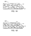
- FIG. 1A is a schematic showing an exemplary material composition 100A in accordance with the present teachings.
- the material composition 100A can include a plurality of graphene-containing particles 120 dispersed or distributed within a polymer matrix 110.
- the plurality of graphene-containing particles 120 is depicted having a consistent size and shape in FIG. 1A , one of ordinary skill in the art will understand that the plurality of graphene-containing particles 120 can have different sizes, and/or shapes.
- the material composition depicted in FIG. 1A represents a generalized schematic illustration and that other particles/ fillers/ polymers can be added or existing particles/ fillers/ polymers can be removed or modified.
- graphene refers to a single layer of carbon arranged in a graphite structure where carbon is hexagonally arranged to form a planar condensed ring system.
- the stacking of graphite layers can be, for example, hexagonal or rhombohedral. In some cases, the majority of graphite structures of the graphene can have hexagonal stacking. Carbon atoms in such graphite structures can be generally recognized as being covalently bonded with sp 2 hybridization.
- graphite typically refers to planar sheets of carbon atoms with each atom bonded to three neighbors in a honeycomb-like structure that has a three-dimensional regular order
- graphite does not usually include a single layer of bonded carbon due to the lack of three-dimensional bonding of carbon.
- graphene can include, for example, single layers of elemental bonded carbon having graphite structure(s) (including impurities), as well as graphite where carbon is bonded in three-dimensions with multiple layers.
- graphene can further include fullerene structures, which are generally recognized as compounds including an even number of carbon atoms, which form a cage-like fused ring polycyclic system with five and six membered rings, including exemplary C 60 , C 70 , and C 80 fullerenes or other closed cage structures having three-coordinate carbon atoms.
- FIG. 2A depicts an exemplary schematic for "graphite” having a three-dimensional atomic crystal structure 200A of carbon 210a
- FIG. 2B depicts an exemplary schematic for "graphene” having a two-dimensional atomic crystal structure 200B of carbon 210b in accordance with the present teachings.
- the atomic crystal structures for graphite and graphene can also be found in the journal of MaterialsToday, Vol. 10, 2007 , entitled “Graphene- Carbon in Two Dimensions,” according to various embodiments of the present teachings.
- the graphene-containing particles 120 can be in various forms.
- the graphene-containing particle 120 can have a nanoparticulate structure that has at least one minor dimension, for example, width or diameter, of about 100 nanometers or less and can be in a form of, such as, for example, nanotube, nanofiber, nanoshaft, nanopillar, nanowire, nanorod, and nanoneedle and their various functionalized and derivatized fibril forms, which include nanofibers with exemplary forms of thread, yarn, fabrics, etc.
- the graphene-containing particle 120 can have a dimension at micro-scale and can be in a form of, for example, whisker, rod, filament, caged structure, buckyball (such as buckminsterfullerene), and mixtures thereof.
- the graphene-containing particles 120 can be soluble fragments of graphene received as, for example, sheets or nanotubes, depending on the chemical modification of its graphite structure which takes place. Further embodiments include, but are not limited to, methods of synthesis by which arc discharge, laser ablation, high pressure carbon monoxide (HiPCO), and chemical vapor deposition (CVD) may be used.
- the graphene-containing particles 120 can be in a form of carbon nanotubes with tubes or cylinders formed of one or more graphene layers (e.g., flat layers), which is unlike the one-dimensional non-graphene-containing nanotube known in the prior art.
- the graphene-containing carbon nanotubes can include a single-walled carbon nanotube species (SWNT) including one graphene sheet; or can include a multi-walled carbon nanotube (MWNT) species including multiple layers of graphene sheet, concentrically arranged or nested within one another.
- SWNT single-walled carbon nanotube species
- MWNT multi-walled carbon nanotube
- a single-walled nanotube may resemble a flat sheet that has been rolled up into a seamless cylinder
- a multi-walled nanotube may resemble stacked sheets that have been rolled up into seamless cylinders.
- the graphene-containing particles 120 can be in a form of carbon whiskers with cylindrical filaments where graphene layers are arranged in scroll-like manner with no three-dimensional stacking order.
- the plurality of graphene-containing particles 120 can provide many advantages to the graphene-containing material composition 100.
- the graphene-containing material can facilitate heat removal from electronics devices.
- atomic vibrations of the graphene can be easily moved through its flat structure as compared with other materials, which provides the graphene, for example, a high thermal conductivity.
- the graphene can be used as electrical charge carriers (e.g., for electrons and/or for holes) to move through a solid with effectively zero mass and constant velocity, like photons.
- the graphene can possess an intrinsically-low scattering rate from defects, which implies electronics based on the manipulation of electrons as waves rather than particles.
- graphenes in its pure form can provide a thermal conductivity of about 4 ⁇ 10 3 Wm -1 K -1 or higher, such as ranging from about 4 ⁇ 10 3 Wm -1 K- 1 to about 6 ⁇ 10 3 Wm -1 K -1 .
- This thermal conductivity is much higher as compared with those non-graphene containing materials including non-graphene containing carbon nanotubes, non-graphene containing graphite and/or metals, such as copper and aluminum.
- graphenes can provide mechanical robustness (e.g., high strength and rigidity).
- graphenes can provide a spring constant on the order of about 1 N/m or higher, such as about 1 to 5 N/m, and can provide an exemplary Young's modulus of about 0.5 TPa, which differs from bulk graphite.
- the graphene-containing particles 120 can be used as a filler material distributed within the polymer matrix 110 to substantially control, e.g., enhance, the physical properties, such as, for example, thermal conductivities, or mechanical robustness of the resulting polymer matrices.
- the resulting material can be used as, for example, a fuser material in a variety of fusing subsystems and embodiments.
- polymers can be used for the polymer matrix 110 to provide desired properties according to specific applications.
- the polymers used for the polymer matrix 110 can include, but are not limited to, silicone elastomers, fluoroelastomers, fluoroplastics, thermoelastomers, fluororesins, and/or resins.
- the polymer matrix 110 can include fluoroelastomers, e.g., having a monomeric repeat unit selected from the group consisting of tetrafluoroethylene (TFE), perfluoro(methyl vinyl ether), perfluoro(propyl vinyl ether), perfluoro(ethyl vinyl ether), vinylidene fluoride (VDF or VF2), hexafluoropropylene (HFP), and mixtures thereof.
- TFE tetrafluoroethylene
- VDF or VF2 vinylidene fluoride
- HFP hexafluoropropylene
- fluoroelastomers can include, for example, such as Viton A ® (copolymers of hexafluoropropylene (HFP) and vinylidene fluoride (VDF or VF2)), Viton ®-B, (terpolymers of tetrafluoroethylene (TFE), vinylidene fluoride (VDF) and hexafluoropropylene (HFP); and Viton ®-GF, (tetrapolymers including TFE, VF2, HFP)), as well as Viton E ®, Viton E 60C ®, Viton E430 ®, Viton 910 ®, Viton GH ® and Viton GF ®.
- the Viton ® designations are Trademarks of E.I. DuPont de Nemours, Inc.
- Still other commercially available fluoroelastomer can include, for example, Dyneon TM fluoroelastomers from 3M Company.
- fluoropolymers can include, for example, Fluorel 2170 ®, Fluorel 2174 ®, Fluorel 2176 ®, Fluorel 2177 ® and Fluorel LVS 76 ®, Fluorel ® being a Trademark of 3M Company.
- Additional commercially available materials can include Aflas ® a poly(propylene-tetrafluoroethylene) and Fluorel II ® (LII900) a poly(propylene-tetrafluoroethylenevinylidenefluoride) both also available from 3M Company, as well as the Tecnoflons identified as For-60KIR ®, For-LHF ®, NM ®, For-THF ®, For-TFS ®, TH ®, and TN505 ®, available from Solvay Solexis.
- the polymer matrix 120 can include a fluororesin selected from the group consisting of polytetrafluoroethylene, copolymer of tetrfluoroethylene and hexafluoropropylene, copolymer of tetrafluoroethylene and perfluoro(propyl vinyl ether), copolymer of tetrafluoroethylene and perfluoro(ethyl vinyl ether), and copolymer of tetrafluoroethylene and perfluoro(methyl vinyl ether).
- a fluororesin selected from the group consisting of polytetrafluoroethylene, copolymer of tetrfluoroethylene and hexafluoropropylene, copolymer of tetrafluoroethylene and perfluoro(propyl vinyl ether), copolymer of tetrafluoroethylene and perfluoro(ethyl vinyl ether), and copolymer of tetrafluoroethylene and perfluor
- the polymer matrix 110 can include fluoroplastics including, but not limited to, PFA (polyfluoroalkoxypolytetrafluoroethylene), PTFE (polytetrafluoroethylene), or FEP (fluorinated ethylenepropylene copolymer).
- fluoroplastics including, but not limited to, PFA (polyfluoroalkoxypolytetrafluoroethylene), PTFE (polytetrafluoroethylene), or FEP (fluorinated ethylenepropylene copolymer).
- PFA polyfluoroalkoxypolytetrafluoroethylene
- PTFE polytetrafluoroethylene
- FEP fluorinated ethylenepropylene copolymer
- the polymer matrix 120 can include polymers cross-linked with an effected cross-linking agent (also referred to herein as cross-linker or curing agent).
- an effected cross-linking agent also referred to herein as cross-linker or curing agent.
- the curing agent can incude, a bisphenol compound, a diamino compound, an aminophenol compound, an amino-siloxane compound, an amino-silane or a phenol-silane compound.
- An exemplary bisphenol cross-linker can be Viton® Curative No. 50 (VC-50) available from E. I. du Pont de Nemours, Inc.
- VC-50 can be soluble in a solvent suspension and can be readily available at the reactive sites for cross-linking with, for example, Viton-GF® (E. I. du Pont de Nemours, Inc.), including tetrafluoroethylene (TFE), hexafluoropropylene (HFP), and vinylidene fluoride (VF2).
- Viton-GF® E. I. du Pont de Nemours, Inc.
- TFE tetrafluoroethylene
- HFP hexafluoropropylene
- VF2 vinylidene fluoride
- FIG. 1B Various other fillers, such as conventional filler materials, can also be used in the disclosed material composition, as shown in FIG. 1B .
- a plurality of non-graphene fillers 130 can be additionally dispersed/ distributed within the polymer matrix 110 along with the disclosed graphene-containing particles 120 as similarly described in FIG. 1A .
- the non-graphene fillers 130 can be in a dimensional scale of micron or nano-scale.
- the non-graphene fillers 130 can be organic, inorganic or metallic.
- the non-graphene fillers 130 can include conventional fillers for composite materials, such as, for example, copper particles, copper flakes, copper needles, aluminum oxide, nano-alumina, titanium oxide, silver flakes, aluminum nitride, nickel particles, silicon carbide, silicon nitride, etc.
- any number of combinations the graphene-containing particles 120 and the non-graphene fillers 130 can be contemplated by the present disclosure, so long as at least one of them includes a graphene-containing particle.
- the disclosed material composition 100 can be used for any suitable electrophotographic members and devices.
- FIG. 3 depicts an exemplary electrophotographic member 300 in accordance with the present teachings. It should be readily apparent to one of ordinary skill in the art that the member 300 depicted in FIG. 3 represents generalized schematic illustrations and that other particles/ layers/ substrates can be added or existing particles/ layers/ substrates can be removed or modified.
- the member 300 can be, for example, a fuser member, a fixing member, a pressure member, a donor member useful for electrophotographic devices.
- the member 300 can be in a form of, for example, a roll, a belt, a plate or a sheet.
- the member 300 can include, a substrate 305 and at least one member layer 315 formed over the substrate 305.
- the member 300 can be a fuser roller including at least one member layer 315 formed over an exemplary core substrate 305.
- the core substrate can take the form of a cylindrical tube or a solid cylindrical shaft.
- substrate forms e.g., a belt substrate, can be used to maintain rigidity, structural integrity of the member 300.
- the member layer 315 can include, for example, the material composition 100 as shown in FIGS. 1A-1B .
- the member layer 315 can thus include a plurality of graphene-containing particles, and optionally non-graphene fillers such as metals or metal oxides, dispersed within a polymer matrix as disclosed herein.
- the member layer 315 can be formed directly on the substrate 305.
- one or more additional functional layers can be formed over the member layer 125 and/or between the member layer 315 and the substrate 305.
- the member 300 can have a 2-layer configuration having a compliant/ resilient layer, such as a silicone rubber layer, disposed between the member layer 315 and the core substrate 305, such as a metal used in the related art.
- the member 300 can include a surface layer, for example, including a fluoropolymer, formed over the member layer 315 that is formed over a resilient layer or the substrate 305.
- FIG. 4 depicts a method for forming an exemplary fuser member in accordance with present teachings. Note that while the method 300 of FIG. 4 is illustrated and described below as a series of acts or events, it will be appreciated that the present invention is not limited by the illustrated ordering of such acts or events. For example, some acts may occur in different orders and/or concurrently with other acts or events apart from those illustrated and/or described herein. Also, not all illustrated steps may be required to implement a methodology in accordance with one or more aspects or embodiments of the present invention. Further, one or more of the acts depicted herein may be carried out in one or more separate acts and/or phases.
- a composition dispersion can be prepared to include, for example, a polymer of interest (e.g., Viton GF) as disclosed herein and graphene-containing particles in a suitable solvent depending on the polymer used.
- a polymer of interest e.g., Viton GF
- graphene-containing particles in a suitable solvent depending on the polymer used.
- solvents including, but not limited to, water, methyl ethyl ketone (MEK), methyl isobutyl ketone (MIBK), methyl-tertbutyl ether (MTBB), methyl n-amyl ketone (MAK), tetrahydrofuran (THF), Alkalis, methyl alcohol, ethyl alcohol, acetone, ethyl acetate, butyl acetate, or any other low molecular weight carbonyls, polar solvents, fireproof hydraulic fluids, along with the Wittig reaction solvents such as dimethyl formamide (DMF), dimethyl sulfoxide (DMSO) and N-methyl 2 pyrrolidone (NMP), can be used to prepare the composition dispersion.
- MEK methyl ethyl ketone
- MIBK methyl isobutyl ketone
- MTBB methyl-tertbutyl ether
- MAK methyl n-amyl ket
- the composition dispersion can be formed by first dissolving the polymer in a suitable solvent, followed by adding a plurality of graphene-containing particles into the solvent in an amount to provide desired properties, such as a desired thermal conductivity or mechanical strength.
- the composition dispersion can include graphene of about 1% to about 60 % by weight of the polymer matrix for an enhanced thermal conductivity.
- a mechanical process such as an agitation, sonication or attritor ball milling/ grinding, can be used to facilitate the mixing of the dispersion.
- an agitation set-up fitted with a stir rod and Teflon blade can be used to thoroughly mix the graphene-containing particles with the polymer in the solvent, after which additional chemical curatives, such as curing agent, and optionally other non-graphene fillers such as metal oxides, can be added into the mixed dispersion.
- an electrophotographic member such as a fuser member
- an electrophotographic member can be formed by applying an amount of the composition dispersion (e.g., that includes a desired polymer and its curing agent, a plurality of graphene-containing particles and optionally inorganic fillers in a solvent) to a substrate, such as the substrate 305 in FIG. 3 .
- the application of the composition dispersion to the substrate can be, for example, deposition, coating, molding or extrusion.
- the composite dispersion i.e., the reaction mixture, can be spray coated, flow coated, injection molded onto the substrate.
- the applied composition dispersion can then be solidified, e.g., be cured, to form a member layer, e.g., the layer 315, on the substrate, e.g., the substrate 305 of FIG. 3 .
- the curing process can include, for example, a drying process and/or a step-wise process including temperature ramps. Depending on the composition dispersion, various curing schedules can be used. In various embodiments, following the curing process, the cured member can be cooled, e.g., in a water bath and/or at a room temperature.
- the formed fuser member can have desired properties including thermal conductivity, mechanical strength, and other physical properties, such as wear performance, or release performance.
- additional functional layer(s) can be formed prior to or following the formation of the member layer over the substrate depending on the electrophotographic devices and processes.
Landscapes
- Physics & Mathematics (AREA)
- General Physics & Mathematics (AREA)
- Compositions Of Macromolecular Compounds (AREA)
- Fixing For Electrophotography (AREA)
- Electrophotography Configuration And Component (AREA)
Abstract

Description
- This invention relates generally to material compositions and, more particularly, to graphene-containing material compositions used for electrophotographic devices and processes.
- Many polymers are not inherently thermally conducting (i.e. Viton GF) and have the potential to improve their thermal conductive properties by introducing fillers into the polymer matrix. In the past, filler materials, including copper particles (or flakes or needles), aluminum oxide, nano-alumina, titanium oxide, silver flakes, aluminum nitride, nickel particles, silicon carbide, and silicon nitride, have been introduced into the polymer matrices in order to improve their thermal conductivities.
- Although these thermally conductive polymer matrices have been used in electrophotography, for example, for fusing operation, there is still a great interest in finding other filler materials that would significantly improve the properties of the polymer matrices. For example, composite materials having significantly improved thermal conductivities can reduce run temperatures and can also increase fuser component life. In addition, it is also desired to provide polymer matrices that can reduce paper edge wear of fuser members, since paper edge wear reduces fuser life and causes a high cost. Thus, there is a need to overcome these and other problems of the prior art and to provide material compositions with improved thermal, mechanical and/or electrical properties for members used in electrophotographic printing devices and processes.
- According to various embodiments, the present teachings include an electrophotographic member that includes a substrate and at least one member layer disposed over the substrate. The at least one member layer can further include a plurality of graphene-containing particles dispersed in a polymer matrix in an amount to control at least a thermal conductivity of the eletrophotographic member.
- According to various embodiments, the present teachings also include a method for making an electrophotographic member. In this method, composition dispersion can first be prepared to include a plurality of graphene-containing particles and a polymer. The plurality of graphene-containing particles can be present in an amount to control at least a thermal conductivity of the electrophotographic member. The prepared composition dispersion can then be applied to a substrate and can be solidified over the substrate.
- According to various embodiments, the present teachings further include a method for making an electrophotographic member. In this method, a composition dispersion can be prepared by first dissolving a polymer, such as a fluoropolymer, in a solvent and then admixing a plurality of graphene-containing particles therewith. The prepared composition dispersion can be applied to a substrate and then be solidified to form a polymer matrix over the substrate. In the polymer matrix, the plurality of graphene-containing particles is present in an amount from about 1% to about 60% by weight of the polymer matrix.
- Additional objects and advantages of the invention will be set forth in part in the description which follows, and in part will be obvious from the description, or may be learned by practice of the invention. The objects and advantages of the invention will be realized and attained by means of the elements and combinations particularly pointed out in the appended claims. It is to be understood that both the foregoing general description and the following detailed description are exemplary and explanatory only and are not restrictive of the invention, as claimed.
- The accompanying drawings, which are incorporated in and constitute a part of this specification, illustrate several embodiments of the invention and together with the description, serve to explain the principles of the invention.
-
FIG. 1A is a schematic showing an exemplary material composition in accordance with the present teachings. -
FIG. 1B is a schematic showing another exemplary material composition in accordance with the present teachings. -
FIG. 2A depicts a schematic for graphite having a three-dimensional atomic crystal structure. -
FIG. 2B depicts a schematic for graphene having a two-dimensional atomic crystal structure. -
FIG. 3 depicts an exemplary electrophotographic member using the material compositions ofFIGS. 1A-1B in accordance with the present teachings. -
FIG. 4 depicts a method for forming an exemplary fuser member using the material compositions ofFIGS. 1A-1B in accordance with the present teachings. - Reference will now be made in detail to the present embodiments (exemplary embodiments) of the invention, an example of which is illustrated in the accompanying drawings. Wherever possible, the same reference numbers will be used throughout the drawings to refer to the same or like parts. In the following description, reference is made to the accompanying drawings that form a part thereof, and in which is shown by way of illustration specific exemplary embodiments in which the invention may be practiced. These embodiments are described in sufficient detail to enable those skilled in the art to practice the invention and it is to be understood that other embodiments may be utilized and that changes may be made without departing from the scope of the invention. The following description is, therefore, merely exemplary.
- While the invention has been illustrated with respect to one or more implementations, alterations and/or modifications can be made to the illustrated examples without departing from the spirit and scope of the appended claims.
- Exemplary embodiments provide material compositions useful for electrophotographic devices and processes. The material composition can include a plurality of graphene-containing particles dispersed or distributed in a polymer matrix. Such material composition can be used for electrophotographic members and devices including, but not limited to, a fuser member, a fixing member, a pressure roller, and/or a release donor member. In one embodiment, a material composition dispersion can be applied on a substrate in electrophotography to form a functional member layer to control, or improve, at least one of thermal, mechanical and/or electrical properties.
-
FIG. 1A is a schematic showing anexemplary material composition 100A in accordance with the present teachings. As shown, thematerial composition 100A can include a plurality of graphene-containingparticles 120 dispersed or distributed within apolymer matrix 110. Although the plurality of graphene-containingparticles 120 is depicted having a consistent size and shape inFIG. 1A , one of ordinary skill in the art will understand that the plurality of graphene-containingparticles 120 can have different sizes, and/or shapes. In addition, it should be readily apparent to one of ordinary skill in the art that the material composition depicted inFIG. 1A represents a generalized schematic illustration and that other particles/ fillers/ polymers can be added or existing particles/ fillers/ polymers can be removed or modified. - As used herein, the term "graphene" refers to a single layer of carbon arranged in a graphite structure where carbon is hexagonally arranged to form a planar condensed ring system. The stacking of graphite layers can be, for example, hexagonal or rhombohedral. In some cases, the majority of graphite structures of the graphene can have hexagonal stacking. Carbon atoms in such graphite structures can be generally recognized as being covalently bonded with sp2 hybridization. While the term "graphite" typically refers to planar sheets of carbon atoms with each atom bonded to three neighbors in a honeycomb-like structure that has a three-dimensional regular order, the term "graphite" does not usually include a single layer of bonded carbon due to the lack of three-dimensional bonding of carbon.
- Thus, as used herein, the term "graphene" can include, for example, single layers of elemental bonded carbon having graphite structure(s) (including impurities), as well as graphite where carbon is bonded in three-dimensions with multiple layers. The term "graphene" can further include fullerene structures, which are generally recognized as compounds including an even number of carbon atoms, which form a cage-like fused ring polycyclic system with five and six membered rings, including exemplary C 60, C 70, and C 80 fullerenes or other closed cage structures having three-coordinate carbon atoms.
- For better understanding of the terms "graphite" and "graphene",
FIG. 2A depicts an exemplary schematic for "graphite" having a three-dimensionalatomic crystal structure 200A of carbon 210a, whileFIG. 2B depicts an exemplary schematic for "graphene" having a two-dimensional atomic crystal structure 200B of carbon 210b in accordance with the present teachings. The atomic crystal structures for graphite and graphene can also be found in the journal of MaterialsToday, Vol. 10, 2007, entitled "Graphene- Carbon in Two Dimensions," according to various embodiments of the present teachings. - In various embodiments, the graphene-containing
particles 120 can be in various forms. For example, the graphene-containingparticle 120 can have a nanoparticulate structure that has at least one minor dimension, for example, width or diameter, of about 100 nanometers or less and can be in a form of, such as, for example, nanotube, nanofiber, nanoshaft, nanopillar, nanowire, nanorod, and nanoneedle and their various functionalized and derivatized fibril forms, which include nanofibers with exemplary forms of thread, yarn, fabrics, etc. In various other embodiments, the graphene-containingparticle 120 can have a dimension at micro-scale and can be in a form of, for example, whisker, rod, filament, caged structure, buckyball (such as buckminsterfullerene), and mixtures thereof. - In various embodiments, the graphene-containing
particles 120 can be soluble fragments of graphene received as, for example, sheets or nanotubes, depending on the chemical modification of its graphite structure which takes place. Further embodiments include, but are not limited to, methods of synthesis by which arc discharge, laser ablation, high pressure carbon monoxide (HiPCO), and chemical vapor deposition (CVD) may be used. - In one exemplary embodiment, the graphene-containing
particles 120 can be in a form of carbon nanotubes with tubes or cylinders formed of one or more graphene layers (e.g., flat layers), which is unlike the one-dimensional non-graphene-containing nanotube known in the prior art. For example, the graphene-containing carbon nanotubes can include a single-walled carbon nanotube species (SWNT) including one graphene sheet; or can include a multi-walled carbon nanotube (MWNT) species including multiple layers of graphene sheet, concentrically arranged or nested within one another. In various embodiments, a single-walled nanotube (SWNT) may resemble a flat sheet that has been rolled up into a seamless cylinder, while a multi-walled nanotube (MWNT) may resemble stacked sheets that have been rolled up into seamless cylinders. - In another exemplary embodiment, the graphene-containing
particles 120 can be in a form of carbon whiskers with cylindrical filaments where graphene layers are arranged in scroll-like manner with no three-dimensional stacking order. - The plurality of graphene-containing
particles 120 can provide many advantages to the graphene-containing material composition 100. For example, due to the flat shape of graphene structure and ability to be integrated with silicon technology, the graphene-containing material can facilitate heat removal from electronics devices. In addition, atomic vibrations of the graphene can be easily moved through its flat structure as compared with other materials, which provides the graphene, for example, a high thermal conductivity. Further, the graphene can be used as electrical charge carriers (e.g., for electrons and/or for holes) to move through a solid with effectively zero mass and constant velocity, like photons. Furthermore, the graphene can possess an intrinsically-low scattering rate from defects, which implies electronics based on the manipulation of electrons as waves rather than particles. - For example, graphenes in its pure form can provide a thermal conductivity of about 4 × 10³ Wm-1K-1 or higher, such as ranging from about 4 ×10³ Wm-1K-1 to about 6 × 10³ Wm-1K-1. This thermal conductivity is much higher as compared with those non-graphene containing materials including non-graphene containing carbon nanotubes, non-graphene containing graphite and/or metals, such as copper and aluminum. In addition, graphenes can provide mechanical robustness (e.g., high strength and rigidity). For example, graphenes can provide a spring constant on the order of about 1 N/m or higher, such as about 1 to 5 N/m, and can provide an exemplary Young's modulus of about 0.5 TPa, which differs from bulk graphite.
- Referring back to
FIG. 1 , the graphene-containingparticles 120 can be used as a filler material distributed within thepolymer matrix 110 to substantially control, e.g., enhance, the physical properties, such as, for example, thermal conductivities, or mechanical robustness of the resulting polymer matrices. The resulting material can be used as, for example, a fuser material in a variety of fusing subsystems and embodiments. - Various polymers can be used for the
polymer matrix 110 to provide desired properties according to specific applications. The polymers used for thepolymer matrix 110 can include, but are not limited to, silicone elastomers, fluoroelastomers, fluoroplastics, thermoelastomers, fluororesins, and/or resins. For example, thepolymer matrix 110 can include fluoroelastomers, e.g., having a monomeric repeat unit selected from the group consisting of tetrafluoroethylene (TFE), perfluoro(methyl vinyl ether), perfluoro(propyl vinyl ether), perfluoro(ethyl vinyl ether), vinylidene fluoride (VDF or VF2), hexafluoropropylene (HFP), and mixtures thereof. - Commercially available fluoroelastomers can include, for example, such as Viton A ® (copolymers of hexafluoropropylene (HFP) and vinylidene fluoride (VDF or VF2)), Viton ®-B, (terpolymers of tetrafluoroethylene (TFE), vinylidene fluoride (VDF) and hexafluoropropylene (HFP); and Viton ®-GF, (tetrapolymers including TFE, VF2, HFP)), as well as Viton E ®, Viton E 60C ®, Viton E430 ®, Viton 910 ®, Viton GH ® and Viton GF ®. The Viton ® designations are Trademarks of E.I. DuPont de Nemours, Inc. Still other commercially available fluoroelastomer can include, for example, Dyneon ™ fluoroelastomers from 3M Company.
- Other commercially available fluoropolymers can include, for example, Fluorel 2170 ®, Fluorel 2174 ®, Fluorel 2176 ®, Fluorel 2177 ® and Fluorel LVS 76 ®, Fluorel ® being a Trademark of 3M Company. Additional commercially available materials can include Aflas ® a poly(propylene-tetrafluoroethylene) and Fluorel II ® (LII900) a poly(propylene-tetrafluoroethylenevinylidenefluoride) both also available from 3M Company, as well as the Tecnoflons identified as For-60KIR ®, For-LHF ®, NM ®, For-THF ®, For-TFS ®, TH ®, and TN505 ®, available from Solvay Solexis.
- In various embodiments, the
polymer matrix 120 can include a fluororesin selected from the group consisting of polytetrafluoroethylene, copolymer of tetrfluoroethylene and hexafluoropropylene, copolymer of tetrafluoroethylene and perfluoro(propyl vinyl ether), copolymer of tetrafluoroethylene and perfluoro(ethyl vinyl ether), and copolymer of tetrafluoroethylene and perfluoro(methyl vinyl ether). - In various embodiments, the
polymer matrix 110 can include fluoroplastics including, but not limited to, PFA (polyfluoroalkoxypolytetrafluoroethylene), PTFE (polytetrafluoroethylene), or FEP (fluorinated ethylenepropylene copolymer). These fluoropolymers can be commercially available from various designations, such as Teflon ® PFA, Teflon ® PTFE, Teflon ® FEP. - In various embodiments, the
polymer matrix 120 can include polymers cross-linked with an effected cross-linking agent (also referred to herein as cross-linker or curing agent). For example, when the polymer matrix includes a vinylidene-fluoride-containing fluoroelastomer, the curing agent can incude, a bisphenol compound, a diamino compound, an aminophenol compound, an amino-siloxane compound, an amino-silane or a phenol-silane compound. An exemplary bisphenol cross-linker can be Viton® Curative No. 50 (VC-50) available from E. I. du Pont de Nemours, Inc. VC-50 can be soluble in a solvent suspension and can be readily available at the reactive sites for cross-linking with, for example, Viton-GF® (E. I. du Pont de Nemours, Inc.), including tetrafluoroethylene (TFE), hexafluoropropylene (HFP), and vinylidene fluoride (VF2). - Various other fillers, such as conventional filler materials, can also be used in the disclosed material composition, as shown in
FIG. 1B . InFIG. 1B , a plurality ofnon-graphene fillers 130 can be additionally dispersed/ distributed within thepolymer matrix 110 along with the disclosed graphene-containingparticles 120 as similarly described inFIG. 1A . - In various embodiments, the
non-graphene fillers 130 can be in a dimensional scale of micron or nano-scale. Thenon-graphene fillers 130 can be organic, inorganic or metallic. In various embodiments, thenon-graphene fillers 130 can include conventional fillers for composite materials, such as, for example, copper particles, copper flakes, copper needles, aluminum oxide, nano-alumina, titanium oxide, silver flakes, aluminum nitride, nickel particles, silicon carbide, silicon nitride, etc. In various embodiments, any number of combinations the graphene-containingparticles 120 and thenon-graphene fillers 130 can be contemplated by the present disclosure, so long as at least one of them includes a graphene-containing particle. - In various embodiments, the disclosed material composition 100 can be used for any suitable electrophotographic members and devices. For example,
FIG. 3 depicts anexemplary electrophotographic member 300 in accordance with the present teachings. It should be readily apparent to one of ordinary skill in the art that themember 300 depicted inFIG. 3 represents generalized schematic illustrations and that other particles/ layers/ substrates can be added or existing particles/ layers/ substrates can be removed or modified. - In various embodiments, the
member 300 can be, for example, a fuser member, a fixing member, a pressure member, a donor member useful for electrophotographic devices. Themember 300 can be in a form of, for example, a roll, a belt, a plate or a sheet. As shown inFIG. 3 , themember 300 can include, asubstrate 305 and at least onemember layer 315 formed over thesubstrate 305. - In various embodiments, the
member 300 can be a fuser roller including at least onemember layer 315 formed over anexemplary core substrate 305. In various embodiments, the core substrate can take the form of a cylindrical tube or a solid cylindrical shaft. One of ordinary skill in the art will understand that other substrate forms, e.g., a belt substrate, can be used to maintain rigidity, structural integrity of themember 300. - The
member layer 315 can include, for example, the material composition 100 as shown inFIGS. 1A-1B . Themember layer 315 can thus include a plurality of graphene-containing particles, and optionally non-graphene fillers such as metals or metal oxides, dispersed within a polymer matrix as disclosed herein. As shown, themember layer 315 can be formed directly on thesubstrate 305. In various embodiments, one or more additional functional layers, depending on the member applications, can be formed over the member layer 125 and/or between themember layer 315 and thesubstrate 305. - In an exemplary embodiment, the
member 300 can have a 2-layer configuration having a compliant/ resilient layer, such as a silicone rubber layer, disposed between themember layer 315 and thecore substrate 305, such as a metal used in the related art. In another exemplary embodiment, themember 300 can include a surface layer, for example, including a fluoropolymer, formed over themember layer 315 that is formed over a resilient layer or thesubstrate 305. - Various embodiments can also include methods for forming the disclosed material composition (see
FIGS. 1A-1B ) and for forming the electrophotographic member (seeFIG. 3). FIG. 4 depicts a method for forming an exemplary fuser member in accordance with present teachings. Note that while themethod 300 ofFIG. 4 is illustrated and described below as a series of acts or events, it will be appreciated that the present invention is not limited by the illustrated ordering of such acts or events. For example, some acts may occur in different orders and/or concurrently with other acts or events apart from those illustrated and/or described herein. Also, not all illustrated steps may be required to implement a methodology in accordance with one or more aspects or embodiments of the present invention. Further, one or more of the acts depicted herein may be carried out in one or more separate acts and/or phases. - At 410 in
FIG. 4 , a composition dispersion can be prepared to include, for example, a polymer of interest (e.g., Viton GF) as disclosed herein and graphene-containing particles in a suitable solvent depending on the polymer used. Various solvents including, but not limited to, water, methyl ethyl ketone (MEK), methyl isobutyl ketone (MIBK), methyl-tertbutyl ether (MTBB), methyl n-amyl ketone (MAK), tetrahydrofuran (THF), Alkalis, methyl alcohol, ethyl alcohol, acetone, ethyl acetate, butyl acetate, or any other low molecular weight carbonyls, polar solvents, fireproof hydraulic fluids, along with the Wittig reaction solvents such as dimethyl formamide (DMF), dimethyl sulfoxide (DMSO) and N-methyl 2 pyrrolidone (NMP), can be used to prepare the composition dispersion. For example, the composition dispersion can be formed by first dissolving the polymer in a suitable solvent, followed by adding a plurality of graphene-containing particles into the solvent in an amount to provide desired properties, such as a desired thermal conductivity or mechanical strength. In an exemplary embodiment, the composition dispersion can include graphene of about 1% to about 60 % by weight of the polymer matrix for an enhanced thermal conductivity. - In various embodiments, when preparing the composition dispersion, a mechanical process, such as an agitation, sonication or attritor ball milling/ grinding, can be used to facilitate the mixing of the dispersion. For example, an agitation set-up fitted with a stir rod and Teflon blade can be used to thoroughly mix the graphene-containing particles with the polymer in the solvent, after which additional chemical curatives, such as curing agent, and optionally other non-graphene fillers such as metal oxides, can be added into the mixed dispersion.
- At 420, an electrophotographic member, such as a fuser member, can be formed by applying an amount of the composition dispersion (e.g., that includes a desired polymer and its curing agent, a plurality of graphene-containing particles and optionally inorganic fillers in a solvent) to a substrate, such as the
substrate 305 inFIG. 3 . The application of the composition dispersion to the substrate can be, for example, deposition, coating, molding or extrusion. In an exemplary embodiment, the composite dispersion, i.e., the reaction mixture, can be spray coated, flow coated, injection molded onto the substrate. - At 430, the applied composition dispersion can then be solidified, e.g., be cured, to form a member layer, e.g., the
layer 315, on the substrate, e.g., thesubstrate 305 ofFIG. 3 . The curing process can include, for example, a drying process and/or a step-wise process including temperature ramps. Depending on the composition dispersion, various curing schedules can be used. In various embodiments, following the curing process, the cured member can be cooled, e.g., in a water bath and/or at a room temperature. - In various embodiments, the formed fuser member can have desired properties including thermal conductivity, mechanical strength, and other physical properties, such as wear performance, or release performance. In various embodiments, additional functional layer(s) can be formed prior to or following the formation of the member layer over the substrate depending on the electrophotographic devices and processes.
- Other embodiments of the invention will be apparent to those skilled in the art from consideration of the specification and practice of the invention disclosed herein. It is intended that the specification and examples be considered as exemplary only, with the scope of the invention being indicated by the following claims.
Claims (15)
- An electrophotographic member comprising:a substrate; andat least one member layer disposed over the substrate; wherein the at least one member layer comprises a plurality of graphene-containing particles dispersed in a polymer matrix in an amount to control at least a thermal conductivity of the eletrophotographic member.
- The member of claim 1, wherein each particle of the plurality of graphene-containing particles comprises:- a nanotube, a nanofiber, a nanoshaft, a nanopillar, a nanowire, a nanorod, a nanoneedle, a nanofiber and mixtures thereof; or- a single wall carbon nanotube (SWCNT), a multi-wall carbon nanotube (MWCNT) and mixtures thereof; or- a whisker, a fiber, a rod, a filament, a tube, a caged structure, a buckyball, and mixtures thereof.
- The member of claim 1, wherein the plurality of graphene-containing particles comprises:- a thermal conductivity of about 4 ×10³ Wm-1 K-1 or higher; or- has a spring constant of about 1 N/m or higher; or- presents in the polymer matrix in an amount from about 1% to about 60% by weight of the polymer matrix.
- The member of claim 1, wherein the polymer matrix comprises one or more polymers selected from the group consisting of silicone elastomers, fluoroelastomers, thermoelastomers, resins, fluororesins and fluoroplastics.
- The member of claim 1, wherein the polymer matrix comprises:- a fluoroelastomer having a monomeric repeat unit selected from the group consisting of tetrafluoroethylene, perfluoro(methyl vinyl ether), perfluoro(propyl vinyl ether), perfluoro(ethyl vinyl ether), vinylidene fluoride, hexafluoropropylene, and mixtures thereof; or- a vinylidene fluoride-containing fluoroelastomer cross-linked with a curing agent that is selected from a group consisting of a bisphenol compound, a diamino compound, an aminophenol compound, an amino-siloxane compound, an amino-silane, and phenol-silane compound; or- a fluororesin selected from the group consisting of polytetrafluoroethylene, copolymer of tetrfluoroethylene and hexafluoropropylene, copolymer of tetrafluoroethylene and perfluoro(propyl vinyl ether), copolymer of tetrafluoroethylene and perfluoro(ethyl vinyl ether), and copolymer of tetrafluoroethylene and perfluoro(methyl vinyl ether).
- The member of claim 1, further comprising one or more non-graphene filler particles dispersed in the polymer matrix, wherein the one or more non-graphene filler particles comprise metals, or metal oxides.
- The member of claim 1, wherein the substrate is in a form of a cylinder, a belt or a sheet.
- A method for making an electrophotographic member comprising:forming a composition dispersion comprising a plurality of graphene-containing particles and a polymer, wherein the plurality of graphene-containing particles are provided in an amount to control at least a thermal conductivity of the electrophotographic member;applying the formed composition dispersion to a substrate; andsolidifying the applied composition dispersion over the substrate.
- The method of claim 8, wherein the composition dispersion further comprises a cross-linking agent for cross-linking the polymer, and optionally a plurality of non-graphene filler particles dispersed in a solvent.
- The method of claim 8, wherein each particle of the plurality of graphene-containing particles comprises a nanotube, a nanofiber, a nanoshaft, a nanopillar, a nanowire, a nanorod, a nanoneedle, a nanofiber, a whisker, a fiber, a rod, a filament, a tube, a caged structure, a buckyball, and mixtures thereof.
- The method of claim 8, wherein the plurality of graphene-containing particles is present in an amount from about 1% to about 60% by weight of the polymer.
- The method of claim 8, wherein the polymer is selected from the group consisting of silicone elastomers, fluoroelastomers, thermoelastomers, resins, fluororesins and fluoroplastics.
- The method of claim 8, wherein the substrate is in a form of a cylinder, a belt or a sheet.
- An electrophotographic member formed by the method of claim 8, wherein the electrophotographic member comprises a fuser member, a fixing member, a pressure member, or a release donor member.
- The method of claim 8, further comprising
dissolving a polymer in a solvent, wherein the polymer comprises a fluoropolymer; wherein
the composition dispersion is formed by admixing a plurality of graphene-containing particles with the solvent containing the polymer;
the applied composition dispersion is solidifying to form a polymer matrix over the substrate, and the plurality of graphene-containing particles is present in the polymer matrix in an amount from about 1% to about 60% by weight of the polymer.
Applications Claiming Priority (1)
| Application Number | Priority Date | Filing Date | Title |
|---|---|---|---|
| US12/361,131 US8173337B2 (en) | 2009-01-28 | 2009-01-28 | Fuser material composition comprising of a polymer matrix with the addition of graphene-containing particles |
Publications (2)
| Publication Number | Publication Date |
|---|---|
| EP2214062A1 true EP2214062A1 (en) | 2010-08-04 |
| EP2214062B1 EP2214062B1 (en) | 2018-07-04 |
Family
ID=42072795
Family Applications (1)
| Application Number | Title | Priority Date | Filing Date |
|---|---|---|---|
| EP10151217.6A Not-in-force EP2214062B1 (en) | 2009-01-28 | 2010-01-20 | Electrophotographic member comprised of a polymer matrix with the addition of graphene-containing particles |
Country Status (5)
| Country | Link |
|---|---|
| US (1) | US8173337B2 (en) |
| EP (1) | EP2214062B1 (en) |
| JP (1) | JP2010176124A (en) |
| CN (1) | CN101852998B (en) |
| CA (1) | CA2690482C (en) |
Families Citing this family (21)
| Publication number | Priority date | Publication date | Assignee | Title |
|---|---|---|---|---|
| US10216129B2 (en) * | 2009-01-29 | 2019-02-26 | Xerox Corporation | Intermediate layer comprising CNT polymer nanocomposite materials in fusers |
| EP2630670B1 (en) | 2010-10-18 | 2015-07-01 | Wake Forest University | Thermoelectric apparatus and applications thereof |
| US8216661B2 (en) * | 2010-10-19 | 2012-07-10 | Xerox Corporation | Variable gloss fuser coating material comprised of a polymer matrix with the addition of alumina nano fibers |
| US8790774B2 (en) * | 2010-12-27 | 2014-07-29 | Xerox Corporation | Fluoroelastomer nanocomposites comprising CNT inorganic nano-fillers |
| CN102174236B (en) * | 2011-03-16 | 2012-09-19 | 哈尔滨师范大学 | Preparation method of a high dielectric constant polyvinylidene fluoride-based composite material |
| US8431217B2 (en) | 2011-09-12 | 2013-04-30 | Xerox Corporation | Core-shell particles and fuser member made therefrom |
| CN102649860A (en) * | 2012-04-24 | 2012-08-29 | 浙江大学 | Graphene/PTFE (Polytetrafluoroethylene) nanometer compound material and preparation method thereof |
| US9056958B2 (en) * | 2012-06-14 | 2015-06-16 | Xerox Corporation | Fuser member |
| EP2874576A4 (en) * | 2012-07-23 | 2016-02-17 | Ohio Willow Wood Co | Polymeric prosthetic and orthotic devices with heat control capabilities |
| KR101813643B1 (en) | 2012-08-22 | 2018-01-30 | 에스프린팅솔루션 주식회사 | method of forming thin resistive heating layer, heating member adopting the thin resistive heating layer, and fusing device and image forming apparatus adopting the heating member |
| US9061806B2 (en) * | 2012-08-30 | 2015-06-23 | Thomas & Betts International, Llc | Cable ties employing a nylon/graphene composite |
| US8934826B2 (en) | 2013-05-30 | 2015-01-13 | Xerox Corporation | Surface tension interference coating process for precise feature control |
| US9458325B2 (en) | 2013-10-02 | 2016-10-04 | Xerox Corporation | Graphene and fluorpolymer composite |
| US9394421B2 (en) | 2013-10-02 | 2016-07-19 | Xerox Corporation | Method of manufacture for graphene fluoropolymer dispersion |
| US9529312B2 (en) | 2013-10-02 | 2016-12-27 | Xerox Corporation | Graphene and fluoropolymer composite fuser coating |
| JP6679839B2 (en) * | 2014-05-09 | 2020-04-15 | Dic株式会社 | Adhesive tape, manufacturing method thereof, and heat dissipation film |
| CN106744879B (en) * | 2016-12-23 | 2021-03-02 | 成都新柯力化工科技有限公司 | Method for stripping graphene based on extensional rheology and application of graphene |
| JP7073110B2 (en) * | 2017-01-30 | 2022-05-23 | キヤノン株式会社 | Additive-curing liquid silicone rubber mixture, electrophotographic components and their manufacturing methods, and fixing devices |
| CN108091878B (en) * | 2017-12-05 | 2020-06-09 | 四川华昆能源有限责任公司 | Preparation method of graphene carbon nanotube composite conductive framework for lithium-sulfur battery |
| JP7263722B2 (en) * | 2018-09-26 | 2023-04-25 | 富士フイルムビジネスイノベーション株式会社 | Fixing belt, fixing device, process cartridge, image forming apparatus, and base material for fixing belt |
| CN109507859A (en) * | 2018-12-12 | 2019-03-22 | 珠海市汇威打印机耗材有限公司 | A kind of fixing roller and preparation method thereof |
Citations (4)
| Publication number | Priority date | Publication date | Assignee | Title |
|---|---|---|---|---|
| US20080038658A1 (en) * | 2006-08-11 | 2008-02-14 | Sumitomo Rubber Industries, Ltd. | Conductive belt, method of producing same, and image-forming apparatus having same |
| WO2008044643A1 (en) * | 2006-10-11 | 2008-04-17 | Sumitomo Electric Industries, Ltd. | Polyimide tube, method for production thereof, method for production of polyimide varnish, and fixing belt |
| EP1942161A1 (en) * | 2006-12-22 | 2008-07-09 | Xerox Corporation | Compositions of carbon nanotubes |
| US20090245840A1 (en) * | 2008-04-01 | 2009-10-01 | Xerox Corporation | Digital fuser concept using micro hotplate technology |
Family Cites Families (8)
| Publication number | Priority date | Publication date | Assignee | Title |
|---|---|---|---|---|
| US6514650B1 (en) * | 1999-09-02 | 2003-02-04 | Xerox Corporation | Thin perfluoropolymer component coatings |
| JP2005144751A (en) * | 2003-11-12 | 2005-06-09 | Ricoh Co Ltd | Surface releasable member, surface releasable heating member, and heat fixing device using them |
| JP4419583B2 (en) * | 2004-01-28 | 2010-02-24 | 富士ゼロックス株式会社 | Endless belt and fixing belt manufacturing method |
| JP4963008B2 (en) * | 2004-10-29 | 2012-06-27 | 株式会社潤工社 | Roll cover |
| JP2006256323A (en) * | 2005-02-21 | 2006-09-28 | Ist Corp | Tubular object and method of manufacturing the same |
| US7871747B2 (en) * | 2005-09-13 | 2011-01-18 | Ricoh Company, Ltd. | Electrophotographic photoconductor having charge blocking and moire preventing layers |
| JP2007304374A (en) * | 2006-05-12 | 2007-11-22 | Nagano Japan Radio Co | Fixing roller |
| US20080152896A1 (en) * | 2006-12-22 | 2008-06-26 | Carolyn Patricia Moorlag | Process to prepare carbon nanotube-reinforced fluoropolymer coatings |
-
2009
- 2009-01-28 US US12/361,131 patent/US8173337B2/en not_active Expired - Fee Related
-
2010
- 2010-01-20 CA CA2690482A patent/CA2690482C/en not_active Expired - Fee Related
- 2010-01-20 EP EP10151217.6A patent/EP2214062B1/en not_active Not-in-force
- 2010-01-22 JP JP2010012113A patent/JP2010176124A/en active Pending
- 2010-01-27 CN CN201010103852.5A patent/CN101852998B/en not_active Expired - Fee Related
Patent Citations (5)
| Publication number | Priority date | Publication date | Assignee | Title |
|---|---|---|---|---|
| US20080038658A1 (en) * | 2006-08-11 | 2008-02-14 | Sumitomo Rubber Industries, Ltd. | Conductive belt, method of producing same, and image-forming apparatus having same |
| WO2008044643A1 (en) * | 2006-10-11 | 2008-04-17 | Sumitomo Electric Industries, Ltd. | Polyimide tube, method for production thereof, method for production of polyimide varnish, and fixing belt |
| EP2072581A1 (en) * | 2006-10-11 | 2009-06-24 | Sumitomo Electric Industries, Ltd. | Polyimide tube, method for production thereof, method for production of polyimide varnish, and fixing belt |
| EP1942161A1 (en) * | 2006-12-22 | 2008-07-09 | Xerox Corporation | Compositions of carbon nanotubes |
| US20090245840A1 (en) * | 2008-04-01 | 2009-10-01 | Xerox Corporation | Digital fuser concept using micro hotplate technology |
Non-Patent Citations (1)
| Title |
|---|
| JOURNAL OF MATERIALSTODAY, vol. 10, 2007 |
Also Published As
| Publication number | Publication date |
|---|---|
| CN101852998B (en) | 2014-04-30 |
| CN101852998A (en) | 2010-10-06 |
| US20100190100A1 (en) | 2010-07-29 |
| CA2690482A1 (en) | 2010-07-28 |
| JP2010176124A (en) | 2010-08-12 |
| EP2214062B1 (en) | 2018-07-04 |
| CA2690482C (en) | 2017-03-21 |
| US8173337B2 (en) | 2012-05-08 |
Similar Documents
| Publication | Publication Date | Title |
|---|---|---|
| US8173337B2 (en) | Fuser material composition comprising of a polymer matrix with the addition of graphene-containing particles | |
| EP1942161B1 (en) | Compositions of carbon nanotubes | |
| EP2248863B1 (en) | Fuser member comprising a surface coating based on a composition of fluororesin containing fluorinated nano diamonds | |
| US9244406B2 (en) | Nanotube reinforced fluorine-containing composites | |
| JP5635273B2 (en) | Fixing device member and manufacturing method thereof | |
| JP5255267B2 (en) | Method for forming a coating on a fusion member | |
| US8192817B2 (en) | VITON fuser member containing fluorinated nano diamonds | |
| JP5738629B2 (en) | Manufacturing and products of fixing materials | |
| US8211535B2 (en) | Nano-fibrils in a fuser member | |
| JP2010170132A (en) | Printing apparatus with fuser member | |
| JP5785071B2 (en) | Fuser member and manufacturing method thereof | |
| JP5726702B2 (en) | Fuser member, fixing method, and fixing system | |
| JP2015010228A (en) | Fluoroelastomer halloysite nanocomposite | |
| JP2022100950A (en) | Thermally conductive sheet and method for producing the same |
Legal Events
| Date | Code | Title | Description |
|---|---|---|---|
| PUAI | Public reference made under article 153(3) epc to a published international application that has entered the european phase |
Free format text: ORIGINAL CODE: 0009012 |
|
| AK | Designated contracting states |
Kind code of ref document: A1 Designated state(s): AT BE BG CH CY CZ DE DK EE ES FI FR GB GR HR HU IE IS IT LI LT LU LV MC MK MT NL NO PL PT RO SE SI SK SM TR |
|
| AX | Request for extension of the european patent |
Extension state: AL BA RS |
|
| 17P | Request for examination filed |
Effective date: 20110204 |
|
| 17Q | First examination report despatched |
Effective date: 20151006 |
|
| STAA | Information on the status of an ep patent application or granted ep patent |
Free format text: STATUS: EXAMINATION IS IN PROGRESS |
|
| GRAP | Despatch of communication of intention to grant a patent |
Free format text: ORIGINAL CODE: EPIDOSNIGR1 |
|
| STAA | Information on the status of an ep patent application or granted ep patent |
Free format text: STATUS: GRANT OF PATENT IS INTENDED |
|
| INTG | Intention to grant announced |
Effective date: 20180323 |
|
| GRAS | Grant fee paid |
Free format text: ORIGINAL CODE: EPIDOSNIGR3 |
|
| GRAA | (expected) grant |
Free format text: ORIGINAL CODE: 0009210 |
|
| STAA | Information on the status of an ep patent application or granted ep patent |
Free format text: STATUS: THE PATENT HAS BEEN GRANTED |
|
| AK | Designated contracting states |
Kind code of ref document: B1 Designated state(s): AT BE BG CH CY CZ DE DK EE ES FI FR GB GR HR HU IE IS IT LI LT LU LV MC MK MT NL NO PL PT RO SE SI SK SM TR |
|
| REG | Reference to a national code |
Ref country code: GB Ref legal event code: FG4D |
|
| REG | Reference to a national code |
Ref country code: CH Ref legal event code: EP |
|
| REG | Reference to a national code |
Ref country code: AT Ref legal event code: REF Ref document number: 1015148 Country of ref document: AT Kind code of ref document: T Effective date: 20180715 |
|
| REG | Reference to a national code |
Ref country code: IE Ref legal event code: FG4D |
|
| REG | Reference to a national code |
Ref country code: DE Ref legal event code: R096 Ref document number: 602010051596 Country of ref document: DE |
|
| REG | Reference to a national code |
Ref country code: NL Ref legal event code: MP Effective date: 20180704 |
|
| REG | Reference to a national code |
Ref country code: LT Ref legal event code: MG4D |
|
| REG | Reference to a national code |
Ref country code: AT Ref legal event code: MK05 Ref document number: 1015148 Country of ref document: AT Kind code of ref document: T Effective date: 20180704 |
|
| PG25 | Lapsed in a contracting state [announced via postgrant information from national office to epo] |
Ref country code: NL Free format text: LAPSE BECAUSE OF FAILURE TO SUBMIT A TRANSLATION OF THE DESCRIPTION OR TO PAY THE FEE WITHIN THE PRESCRIBED TIME-LIMIT Effective date: 20180704 |
|
| PG25 | Lapsed in a contracting state [announced via postgrant information from national office to epo] |
Ref country code: CZ Free format text: LAPSE BECAUSE OF FAILURE TO SUBMIT A TRANSLATION OF THE DESCRIPTION OR TO PAY THE FEE WITHIN THE PRESCRIBED TIME-LIMIT Effective date: 20180704 Ref country code: GR Free format text: LAPSE BECAUSE OF FAILURE TO SUBMIT A TRANSLATION OF THE DESCRIPTION OR TO PAY THE FEE WITHIN THE PRESCRIBED TIME-LIMIT Effective date: 20181005 Ref country code: NO Free format text: LAPSE BECAUSE OF FAILURE TO SUBMIT A TRANSLATION OF THE DESCRIPTION OR TO PAY THE FEE WITHIN THE PRESCRIBED TIME-LIMIT Effective date: 20181004 Ref country code: FI Free format text: LAPSE BECAUSE OF FAILURE TO SUBMIT A TRANSLATION OF THE DESCRIPTION OR TO PAY THE FEE WITHIN THE PRESCRIBED TIME-LIMIT Effective date: 20180704 Ref country code: AT Free format text: LAPSE BECAUSE OF FAILURE TO SUBMIT A TRANSLATION OF THE DESCRIPTION OR TO PAY THE FEE WITHIN THE PRESCRIBED TIME-LIMIT Effective date: 20180704 Ref country code: SE Free format text: LAPSE BECAUSE OF FAILURE TO SUBMIT A TRANSLATION OF THE DESCRIPTION OR TO PAY THE FEE WITHIN THE PRESCRIBED TIME-LIMIT Effective date: 20180704 Ref country code: BG Free format text: LAPSE BECAUSE OF FAILURE TO SUBMIT A TRANSLATION OF THE DESCRIPTION OR TO PAY THE FEE WITHIN THE PRESCRIBED TIME-LIMIT Effective date: 20181004 Ref country code: IS Free format text: LAPSE BECAUSE OF FAILURE TO SUBMIT A TRANSLATION OF THE DESCRIPTION OR TO PAY THE FEE WITHIN THE PRESCRIBED TIME-LIMIT Effective date: 20181104 Ref country code: PL Free format text: LAPSE BECAUSE OF FAILURE TO SUBMIT A TRANSLATION OF THE DESCRIPTION OR TO PAY THE FEE WITHIN THE PRESCRIBED TIME-LIMIT Effective date: 20180704 Ref country code: LT Free format text: LAPSE BECAUSE OF FAILURE TO SUBMIT A TRANSLATION OF THE DESCRIPTION OR TO PAY THE FEE WITHIN THE PRESCRIBED TIME-LIMIT Effective date: 20180704 |
|
| PG25 | Lapsed in a contracting state [announced via postgrant information from national office to epo] |
Ref country code: LV Free format text: LAPSE BECAUSE OF FAILURE TO SUBMIT A TRANSLATION OF THE DESCRIPTION OR TO PAY THE FEE WITHIN THE PRESCRIBED TIME-LIMIT Effective date: 20180704 Ref country code: HR Free format text: LAPSE BECAUSE OF FAILURE TO SUBMIT A TRANSLATION OF THE DESCRIPTION OR TO PAY THE FEE WITHIN THE PRESCRIBED TIME-LIMIT Effective date: 20180704 Ref country code: ES Free format text: LAPSE BECAUSE OF FAILURE TO SUBMIT A TRANSLATION OF THE DESCRIPTION OR TO PAY THE FEE WITHIN THE PRESCRIBED TIME-LIMIT Effective date: 20180704 |
|
| REG | Reference to a national code |
Ref country code: DE Ref legal event code: R097 Ref document number: 602010051596 Country of ref document: DE |
|
| PG25 | Lapsed in a contracting state [announced via postgrant information from national office to epo] |
Ref country code: RO Free format text: LAPSE BECAUSE OF FAILURE TO SUBMIT A TRANSLATION OF THE DESCRIPTION OR TO PAY THE FEE WITHIN THE PRESCRIBED TIME-LIMIT Effective date: 20180704 Ref country code: EE Free format text: LAPSE BECAUSE OF FAILURE TO SUBMIT A TRANSLATION OF THE DESCRIPTION OR TO PAY THE FEE WITHIN THE PRESCRIBED TIME-LIMIT Effective date: 20180704 Ref country code: IT Free format text: LAPSE BECAUSE OF FAILURE TO SUBMIT A TRANSLATION OF THE DESCRIPTION OR TO PAY THE FEE WITHIN THE PRESCRIBED TIME-LIMIT Effective date: 20180704 |
|
| PLBE | No opposition filed within time limit |
Free format text: ORIGINAL CODE: 0009261 |
|
| STAA | Information on the status of an ep patent application or granted ep patent |
Free format text: STATUS: NO OPPOSITION FILED WITHIN TIME LIMIT |
|
| PG25 | Lapsed in a contracting state [announced via postgrant information from national office to epo] |
Ref country code: SM Free format text: LAPSE BECAUSE OF FAILURE TO SUBMIT A TRANSLATION OF THE DESCRIPTION OR TO PAY THE FEE WITHIN THE PRESCRIBED TIME-LIMIT Effective date: 20180704 Ref country code: SK Free format text: LAPSE BECAUSE OF FAILURE TO SUBMIT A TRANSLATION OF THE DESCRIPTION OR TO PAY THE FEE WITHIN THE PRESCRIBED TIME-LIMIT Effective date: 20180704 Ref country code: DK Free format text: LAPSE BECAUSE OF FAILURE TO SUBMIT A TRANSLATION OF THE DESCRIPTION OR TO PAY THE FEE WITHIN THE PRESCRIBED TIME-LIMIT Effective date: 20180704 |
|
| 26N | No opposition filed |
Effective date: 20190405 |
|
| REG | Reference to a national code |
Ref country code: DE Ref legal event code: R119 Ref document number: 602010051596 Country of ref document: DE |
|
| PG25 | Lapsed in a contracting state [announced via postgrant information from national office to epo] |
Ref country code: SI Free format text: LAPSE BECAUSE OF FAILURE TO SUBMIT A TRANSLATION OF THE DESCRIPTION OR TO PAY THE FEE WITHIN THE PRESCRIBED TIME-LIMIT Effective date: 20180704 Ref country code: MC Free format text: LAPSE BECAUSE OF FAILURE TO SUBMIT A TRANSLATION OF THE DESCRIPTION OR TO PAY THE FEE WITHIN THE PRESCRIBED TIME-LIMIT Effective date: 20180704 |
|
| REG | Reference to a national code |
Ref country code: CH Ref legal event code: PL |
|
| GBPC | Gb: european patent ceased through non-payment of renewal fee |
Effective date: 20190120 |
|
| PG25 | Lapsed in a contracting state [announced via postgrant information from national office to epo] |
Ref country code: LU Free format text: LAPSE BECAUSE OF NON-PAYMENT OF DUE FEES Effective date: 20190120 |
|
| REG | Reference to a national code |
Ref country code: BE Ref legal event code: MM Effective date: 20190131 |
|
| REG | Reference to a national code |
Ref country code: IE Ref legal event code: MM4A |
|
| PG25 | Lapsed in a contracting state [announced via postgrant information from national office to epo] |
Ref country code: FR Free format text: LAPSE BECAUSE OF NON-PAYMENT OF DUE FEES Effective date: 20190131 Ref country code: DE Free format text: LAPSE BECAUSE OF NON-PAYMENT OF DUE FEES Effective date: 20190801 |
|
| PG25 | Lapsed in a contracting state [announced via postgrant information from national office to epo] |
Ref country code: BE Free format text: LAPSE BECAUSE OF NON-PAYMENT OF DUE FEES Effective date: 20190131 |
|
| PG25 | Lapsed in a contracting state [announced via postgrant information from national office to epo] |
Ref country code: GB Free format text: LAPSE BECAUSE OF NON-PAYMENT OF DUE FEES Effective date: 20190120 Ref country code: CH Free format text: LAPSE BECAUSE OF NON-PAYMENT OF DUE FEES Effective date: 20190131 Ref country code: LI Free format text: LAPSE BECAUSE OF NON-PAYMENT OF DUE FEES Effective date: 20190131 |
|
| PG25 | Lapsed in a contracting state [announced via postgrant information from national office to epo] |
Ref country code: IE Free format text: LAPSE BECAUSE OF NON-PAYMENT OF DUE FEES Effective date: 20190120 |
|
| PG25 | Lapsed in a contracting state [announced via postgrant information from national office to epo] |
Ref country code: TR Free format text: LAPSE BECAUSE OF FAILURE TO SUBMIT A TRANSLATION OF THE DESCRIPTION OR TO PAY THE FEE WITHIN THE PRESCRIBED TIME-LIMIT Effective date: 20180704 |
|
| PG25 | Lapsed in a contracting state [announced via postgrant information from national office to epo] |
Ref country code: PT Free format text: LAPSE BECAUSE OF FAILURE TO SUBMIT A TRANSLATION OF THE DESCRIPTION OR TO PAY THE FEE WITHIN THE PRESCRIBED TIME-LIMIT Effective date: 20181105 Ref country code: MT Free format text: LAPSE BECAUSE OF NON-PAYMENT OF DUE FEES Effective date: 20190120 |
|
| PG25 | Lapsed in a contracting state [announced via postgrant information from national office to epo] |
Ref country code: CY Free format text: LAPSE BECAUSE OF FAILURE TO SUBMIT A TRANSLATION OF THE DESCRIPTION OR TO PAY THE FEE WITHIN THE PRESCRIBED TIME-LIMIT Effective date: 20180704 |
|
| PG25 | Lapsed in a contracting state [announced via postgrant information from national office to epo] |
Ref country code: HU Free format text: LAPSE BECAUSE OF FAILURE TO SUBMIT A TRANSLATION OF THE DESCRIPTION OR TO PAY THE FEE WITHIN THE PRESCRIBED TIME-LIMIT; INVALID AB INITIO Effective date: 20100120 |
|
| PG25 | Lapsed in a contracting state [announced via postgrant information from national office to epo] |
Ref country code: MK Free format text: LAPSE BECAUSE OF FAILURE TO SUBMIT A TRANSLATION OF THE DESCRIPTION OR TO PAY THE FEE WITHIN THE PRESCRIBED TIME-LIMIT Effective date: 20180704 |