EP2212639B1 - Heat exchanger having baffled manifolds - Google Patents
Heat exchanger having baffled manifolds Download PDFInfo
- Publication number
- EP2212639B1 EP2212639B1 EP07839508.4A EP07839508A EP2212639B1 EP 2212639 B1 EP2212639 B1 EP 2212639B1 EP 07839508 A EP07839508 A EP 07839508A EP 2212639 B1 EP2212639 B1 EP 2212639B1
- Authority
- EP
- European Patent Office
- Prior art keywords
- manifold
- fluid
- heat exchanger
- insert
- inlet
- Prior art date
- Legal status (The legal status is an assumption and is not a legal conclusion. Google has not performed a legal analysis and makes no representation as to the accuracy of the status listed.)
- Not-in-force
Links
- 239000012530 fluid Substances 0.000 claims description 107
- 238000009826 distribution Methods 0.000 claims description 45
- 239000012071 phase Substances 0.000 claims description 25
- 238000005192 partition Methods 0.000 claims description 19
- 239000000203 mixture Substances 0.000 claims description 14
- 239000007791 liquid phase Substances 0.000 claims description 10
- 239000012808 vapor phase Substances 0.000 claims description 10
- 239000003507 refrigerant Substances 0.000 description 14
- 238000005057 refrigeration Methods 0.000 description 7
- 238000007906 compression Methods 0.000 description 3
- 230000000116 mitigating effect Effects 0.000 description 3
- 238000004378 air conditioning Methods 0.000 description 1
- 230000003750 conditioning effect Effects 0.000 description 1
- 238000001816 cooling Methods 0.000 description 1
- 230000002939 deleterious effect Effects 0.000 description 1
- 238000001704 evaporation Methods 0.000 description 1
- 230000008020 evaporation Effects 0.000 description 1
- 230000005484 gravity Effects 0.000 description 1
- 239000008240 homogeneous mixture Substances 0.000 description 1
- 239000003607 modifier Substances 0.000 description 1
- 238000000926 separation method Methods 0.000 description 1
- 239000000126 substance Substances 0.000 description 1
- 230000007704 transition Effects 0.000 description 1
- 238000009827 uniform distribution Methods 0.000 description 1
Images


Classifications
-
- F—MECHANICAL ENGINEERING; LIGHTING; HEATING; WEAPONS; BLASTING
- F28—HEAT EXCHANGE IN GENERAL
- F28D—HEAT-EXCHANGE APPARATUS, NOT PROVIDED FOR IN ANOTHER SUBCLASS, IN WHICH THE HEAT-EXCHANGE MEDIA DO NOT COME INTO DIRECT CONTACT
- F28D1/00—Heat-exchange apparatus having stationary conduit assemblies for one heat-exchange medium only, the media being in contact with different sides of the conduit wall, in which the other heat-exchange medium is a large body of fluid, e.g. domestic or motor car radiators
- F28D1/02—Heat-exchange apparatus having stationary conduit assemblies for one heat-exchange medium only, the media being in contact with different sides of the conduit wall, in which the other heat-exchange medium is a large body of fluid, e.g. domestic or motor car radiators with heat-exchange conduits immersed in the body of fluid
- F28D1/04—Heat-exchange apparatus having stationary conduit assemblies for one heat-exchange medium only, the media being in contact with different sides of the conduit wall, in which the other heat-exchange medium is a large body of fluid, e.g. domestic or motor car radiators with heat-exchange conduits immersed in the body of fluid with tubular conduits
- F28D1/053—Heat-exchange apparatus having stationary conduit assemblies for one heat-exchange medium only, the media being in contact with different sides of the conduit wall, in which the other heat-exchange medium is a large body of fluid, e.g. domestic or motor car radiators with heat-exchange conduits immersed in the body of fluid with tubular conduits the conduits being straight
- F28D1/0535—Heat-exchange apparatus having stationary conduit assemblies for one heat-exchange medium only, the media being in contact with different sides of the conduit wall, in which the other heat-exchange medium is a large body of fluid, e.g. domestic or motor car radiators with heat-exchange conduits immersed in the body of fluid with tubular conduits the conduits being straight the conduits having a non-circular cross-section
- F28D1/05366—Assemblies of conduits connected to common headers, e.g. core type radiators
- F28D1/05391—Assemblies of conduits connected to common headers, e.g. core type radiators with multiple rows of conduits or with multi-channel conduits combined with a particular flow pattern, e.g. multi-row multi-stage radiators
-
- F—MECHANICAL ENGINEERING; LIGHTING; HEATING; WEAPONS; BLASTING
- F25—REFRIGERATION OR COOLING; COMBINED HEATING AND REFRIGERATION SYSTEMS; HEAT PUMP SYSTEMS; MANUFACTURE OR STORAGE OF ICE; LIQUEFACTION SOLIDIFICATION OF GASES
- F25B—REFRIGERATION MACHINES, PLANTS OR SYSTEMS; COMBINED HEATING AND REFRIGERATION SYSTEMS; HEAT PUMP SYSTEMS
- F25B39/00—Evaporators; Condensers
- F25B39/02—Evaporators
- F25B39/028—Evaporators having distributing means
-
- F—MECHANICAL ENGINEERING; LIGHTING; HEATING; WEAPONS; BLASTING
- F28—HEAT EXCHANGE IN GENERAL
- F28F—DETAILS OF HEAT-EXCHANGE AND HEAT-TRANSFER APPARATUS, OF GENERAL APPLICATION
- F28F9/00—Casings; Header boxes; Auxiliary supports for elements; Auxiliary members within casings
- F28F9/02—Header boxes; End plates
- F28F9/0202—Header boxes having their inner space divided by partitions
- F28F9/0204—Header boxes having their inner space divided by partitions for elongated header box, e.g. with transversal and longitudinal partitions
-
- F—MECHANICAL ENGINEERING; LIGHTING; HEATING; WEAPONS; BLASTING
- F28—HEAT EXCHANGE IN GENERAL
- F28F—DETAILS OF HEAT-EXCHANGE AND HEAT-TRANSFER APPARATUS, OF GENERAL APPLICATION
- F28F9/00—Casings; Header boxes; Auxiliary supports for elements; Auxiliary members within casings
- F28F9/02—Header boxes; End plates
- F28F9/026—Header boxes; End plates with static flow control means, e.g. with means for uniformly distributing heat exchange media into conduits
- F28F9/027—Header boxes; End plates with static flow control means, e.g. with means for uniformly distributing heat exchange media into conduits in the form of distribution pipes
- F28F9/0273—Header boxes; End plates with static flow control means, e.g. with means for uniformly distributing heat exchange media into conduits in the form of distribution pipes with multiple holes
-
- F—MECHANICAL ENGINEERING; LIGHTING; HEATING; WEAPONS; BLASTING
- F28—HEAT EXCHANGE IN GENERAL
- F28F—DETAILS OF HEAT-EXCHANGE AND HEAT-TRANSFER APPARATUS, OF GENERAL APPLICATION
- F28F9/00—Casings; Header boxes; Auxiliary supports for elements; Auxiliary members within casings
- F28F9/02—Header boxes; End plates
- F28F9/026—Header boxes; End plates with static flow control means, e.g. with means for uniformly distributing heat exchange media into conduits
- F28F9/0278—Header boxes; End plates with static flow control means, e.g. with means for uniformly distributing heat exchange media into conduits in the form of stacked distribution plates or perforated plates arranged over end plates
Definitions
- the present disclosure relates to heat exchangers. More particularly, the present disclosure relates to heat exchangers having baffled manifolds.
- the subject-matter of claim 1 differs from the heat exchanger disclosed in this document in that it comprises one or more baffles within the outside of the second manifold, the baffles being configured to ensure that the fluid enters the plurality of parallel channels of the second pass as substantially homogeneous two-phase mixture.
- Refrigeration systems are well known in the art and ubiquitous in such industries as food service, chemical, residential and commercial cooling, and automotive. On a larger scale, heat exchangers are required for office buildings and for residential purposes. Lack of efficiency is a great concern with such systems.
- Traditional refrigeration cycles, or air conditioners include a compressor, a condenser, an expansion valve, an evaporator, and a refrigerant whose evaporation creates the cool temperature.
- the evaporator and condenser are heat exchangers having a series of parallel channels, which provide parallel refrigerant paths. When the refrigerant passes through the expansion valve, a pressure and temperature drop occurs.
- the term "maldistribution" of two-phase fluid shall mean that one phase of the fluid (e.g., liquid-phase) predominantly flows through a particular portion of the evaporator, while that the other phase of the fluid (e.g., vapor-phase) predominantly flows through a different portion of the evaporator.
- WO 2006/083451 discloses a heat exchanger with perforated plate header.
- Heat exchanger 10 includes one or more baffles 12 within one or more manifolds 18, 20.
- baffles 12 are configured to limit the movement of the fluid along an axis (A) of manifold 18, 20, which mitigates separation of the two-phase fluid and ensures uniform distribution within the channels of heat exchanger 10.
- FIG. 1 illustrates heat exchanger 10 as a multipass heat exchanger having a first pass 14 and a second pass 16.
- baffles 12 it is contemplated by the present disclosure for baffles 12 to find equal use with any parallel path heat exchanger having more than two passes.
- Heat exchanger 10 includes a first manifold 18 and a second manifold 20 that are in fluid communication with one another by way of a plurality of parallel channels 22.
- heat exchanger 10 is a micro-channel heat exchanger having a plurality of micro-channels 22.
- baffles 12 it is contemplated by the present disclosure for baffles 12 to find equal use with any type of parallel path heat exchanger having channels 22 of any desired size.
- First manifold 18 includes a first partition 24-1 and second manifold 20 includes a second partition 24-2.
- Partitions 24-1, 24-2 are configured to separate manifolds 18, 20 and channels 22 into first pass 14 and second pass 16, respectively, along a line 26.
- Partition 24-1 divides first manifold 18 into an inlet side 28 and an outlet side 30.
- partition 24-2 divides second manifold 20 into an inlet side 32 and an outlet side 34.
- Heat exchanger 10 includes a distribution insert 36 within inlet side 28 of first manifold 18. Further, heat exchanger 10 includes a collection insert 38 within outlet side 32 of second manifold 20 and a distribution insert 40 within inlet side 34 of second manifold 20. In the illustrated embodiment, collection insert 38 and distribution insert 40 are shown as one unitary member. However, it is contemplated by the present disclosure for collection and distribution inserts 38, 40 to be separate items.
- Heat exchanger 10 finds particular use with a fluid 42, such as a refrigerant of a vapor-compression or air conditioning circuit.
- Fluid 42 can be a single-phase fluid or a two-phase fluid.
- fluid 42 traveling through heat exchanger 10 can be in a vapor-phase and/or a liquid-phase.
- the flow of fluid 26 is represented by one or more directional arrows.
- Distribution insert 36 includes a plurality of openings 44 defined therein. Openings 44 place distribution insert 36 in fluid communication with inlet side 28 of first manifold 18. Collection insert 38 includes a plurality of openings 46 defined therein. Openings 46 place collection insert 38 in fluid communication with outlet side 32 of second manifold 20. Distribution insert 40 includes a plurality of openings 48 defined therein. Openings 48 place distribution insert 40 in fluid communication with inlet side 34 of second manifold 20.
- fluid 42 enters heat exchanger 10 through distribution insert 36 within inlet side 28 of first manifold 18.
- the fluid 42 is prevented from flowing from inlet side 28 to outlet side 30 by partition 24-1. Rather, distribution insert 36 distributes fluid 42 into inlet side 28 of first manifold 18 through openings 44.
- distribution insert 36 assists in passing fluid 42 in a substantially homogeneous state to inlet side 28 of first manifold 18. More particularly, it has been determined that distribution insert 36 assists in mixing fluid 42 so that the fluid within inlet side 28 of first manifold 18 is a substantially homogeneous mixture of liquid-phase fluid and vapor-phase fluid.
- Openings 44 are preferably of variable size to effectively mix and distribute fluid 42 flowing into inlet side 28 of first manifold 18. Openings 44 can have a dimension that can be uniform across distribution insert 36, or the dimension of the openings can increase in size in a direction from first pass 14 to second pass 16. For example, openings 44 can increase in dimension further downstream of the fluid flow path can achieve a greater degree of fluid distribution.
- baffles 12 are configured to limit the movement of fluid 42 within the inlet side 28 of first manifold 18. More specifically, and without wishing to be bound by any particular theory, it has been determined by the present disclosure that the liquid and vapor phases of fluid 42 can be separated by the fluidic forces within heat exchanger 10 such that these forces can cause one of the two phases to be forced towards partition 24-1. This movement of fluid 42 along the axis of first manifold 18 towards partition 24-1 can be limited by baffles 12. Thus, baffles 12 assist in mitigating maldistribution of fluid 42 within channels 22 of first pass 14.
- heat exchanger 10 includes a mixing device, illustrated as distribution insert 36, to effectively mix fluid 42 as the fluid enters inlet side 28 so that both phases of the fluid are in a substantially homogeneous two-phase mixture within inlet side 28.
- heat exchanger 10 includes one or more baffles 12 (two shown) to prevent the fluidic forces within inlet side 28 from separating the two phases from one another and forcing one of the two phases towards partition 24-1. In this manner, baffles 12 ensure that fluid 42 enters channels 22 of first pass 14 in the substantially homogeneous two-phase mixture, which mitigates maldistribution of the fluid within the channels.
- Fluid 42 enters channels 22 from inlet side 28 of first manifold 18, flows through the channels and exits the channels into outlet side 32 of second manifold 20.
- fluid 42 is prevented from flowing directly to inlet side 34 of second manifold 20 by partition 24-2.
- fluid 42 flows from outlet side 32 to collection insert 38 through openings 46. Then, fluid 42 flows from collection insert 38 to distribution insert 40. In this manner, fluid 42 flows from first pass 14 across line 26 into second pass 16. Next, fluid 42 flows from distribution insert 40 through openings 48 into inlet side 34 of second manifold 20.
- collection insert 38 and distribution insert 40 assists in passing fluid 42 in a substantially homogeneous two-phase state to inlet side 34 of second manifold 20. More specifically, collection insert 38 and distribution insert 40 each mix fluid 42 as the fluid passes therethrough.
- Baffles 12 within second manifold 20 are configured to limit the movement of fluid 42 within inlet side 34 along the axis (A) of the second manifold. Thus, baffles 12 can also assist in mitigating maldistribution of fluid 42 within channels 22 of second pass 16.
- Fluid 42 enters channels 22 from inlet side 34 of second manifold 20, flows through the channels and exits the channels into outlet side 30 of first manifold 18.
- fluid 42 flows out of the heat exchanger.
- heat exchanger 10 it is contemplated by the present disclosure for heat exchanger 10 to have more than two passes 14, 16, such that fluid 42 flowing from second manifold 20 can enter a third pass (not shown) of channels.
- FIG. 2 An alternate embodiment of heat exchanger 10 having baffles 12 is shown in FIG. 2 .
- openings 44 in distribution insert 36 are illustrated directing fluid 42 in a direction substantially perpendicular (e.g., about ninety degrees) to the direction of flow through channels 22.
- distribution insert 36 is illustrated in FIG. 1 having openings 44 directing fluid 42 in a direction substantially parallel (e.g., about zero degrees) to the direction of flow through channels 22.
- heat exchanger 10 to have distribution insert 36 with openings 44 at any desired angle with respect to the direction of flow through channels 22.
- heat exchanger 10 it is contemplated for heat exchanger 10 to have distribution insert 36 with openings 44 at an angle such as zero degrees ( FIG. 1 ), ninety degrees ( FIG. 2 ), and angle there between, as well as any angle more than ninety degrees.
- the angle of openings 44 it is contemplated for the angle of openings 44 to differ from one another such that some openings may have one angle, while other openings have a different angle.
- distribution insert 36 is shown as a closed ended tube having an end-cap 50 adjacent partition 24-1 , whereas the embodiment of distribution insert 36 shown in FIG. 1 is illustrated as an open ended tube connected to partition 24-1.
- distribution insert 36 is defined by a first wall 52 and a second wall 54, where the first wall is independent of first manifold 18, but the second wall is common with the first manifold. Further, distribution insert 36 is defined by partition 24-1. In contrast, the embodiments of distribution insert 36 shown in FIGS. 1 and 2 have no walls in common with first manifold 18.
- FIG. 4 still another heat exchanger 10 having baffles 12 is shown.
- This heat exchanger 10 which falls outside the scope of the present invention, includes distributing inserts 36 and 40 as described with respect to the embodiment of FIG. 1 .
- this heat exchanger 10 lacks collection insert 38 within outlet side 32 of second manifold 20 as in FIG. 1 .
- heat exchanger 10 illustrated in FIG. 4 includes an external collection-distributor 56.
- External collection-distributor 56 is in fluid communication with outlet side 32 of second manifold 20 via one or more ports 58 (only one shown). Further, external collection-distributor 56 is in fluid communication with inlet side 34 of second manifold 20 via one or more ports 60 (three shown).
- fluid 42 enters channels 22 from inlet side 28 of first manifold 18, flows through the channels and exits the channels into outlet side 32 of second manifold 20.
- fluid 42 is prevented from flowing directly to inlet side 34 of second manifold 20 by partition 24-2.
- fluid 42 flows from outlet side 32 to external collection-distributor 56 through openings 58. Then, fluid 42 flows through external collection-distributor 56 from first pass 14 across line 26 into second pass 16. Next, fluid 42 flows from external collection-distributor 56 through openings 60 into distribution insert 40, which further mixes fluid 42 as the fluid flows from the distribution insert through openings 48 into inlet side 34 of second manifold 20.
- baffles 12 within second manifold 20 are configured to limit the movement of fluid 42 along axis A of the second manifold. Thus, baffles 12 can also assist in mitigating maldistribution of fluid 42 within channels 22 of second pass 16.
- External collection-distributor 56 assists in passing fluid 42 in a substantially homogeneous state to inlet side 34 of second manifold 20.
- the combination of external collection-distributor 56 along with distribution insert 40 adds an additional mixing stage as compared to the embodiment of FIG. 1 .
- external collection-distributor 56 includes a first portion 62 within first pass 14 (i.e., to the left of line 26) and a second portion 64 within second pass 16 (i.e., to the right of line 26).
- first portion 62 functions in a manner similar to collection insert 38 of FIG. 1
- second portion 64 functions in a manner similar to distribution insert 40 of FIG. 1 . Since the embodiment of FIG. 4 includes first portion 62, second portion 64, and distribution insert 40, this embodiment of heat exchanger 10 provides one additional mixing stage of fluid 42 as compared to the embodiment of FIG. 1 .
- FIG. 5 another embodiment of heat exchanger 10 is shown.
- first manifold 18 includes inlet port 66 and outlet port 68 that are configured so that the flow of fluid 42 is in a direction substantially parallel (e.g., about zero degrees) to the flow of fluid through channels 22.
- heat exchanger 10 illustrated in FIG. 1 having ports 66, 68 directing fluid 42 in a direction substantially perpendicular (e.g., about ninety degrees) to the direction of flow through channels 22.
- ports 66, 68 at any desired angle with respect to the direction of flow through channels 22.
- heat exchanger 10 to have one or both ports 66, 68 at an angle selected from the group consisting of zero degrees, ninety degrees, and any combinations thereof.
- first manifold 18 includes collection insert 38 within outlet side 30 of the first manifold. Collection insert 38 within outlet side 30 of first manifold 18 functions as described with respect to collection insert 38 within outlet side 32 of second manifold 20 of the embodiment of FIG. 1 . Accordingly, heat exchanger 10 in the embodiment of FIG. 5 provides for additional mixing of fluid 42 before the fluid exits the heat exchanger.
- heat exchanger 10 includes a second collection-distributor 70 at second manifold 20.
- Second collection-distributor 70 is in fluid communication with collection insert 38 via one or more (only one shown) openings 72 and with distributing insert 40 via one or more (only one shown) openings 74.
- partition 24-2 includes an extension 76 preventing direction fluid communication between collection insert 38 and distributing insert 40.
- heat exchanger 10 finds use in any refrigeration circuit.
- heat exchanger 10 is shown in use in a refrigeration circuit 80.
- refrigeration circuit 80 has an evaporator 82 and a condenser 84.
- heat exchanger 10 can find use as evaporator 82, as condenser 84, or both.
- Heat exchanger 10 can be arranged within circuit 80 so that the plurality of channels 22 are arranged in any desired manner.
- heat exchanger 10 can be arranged within circuit 80 so that channels 22 are vertically arranged. In this manner, heat exchanger 10 can be arranged within circuit 80 so that refrigerant 42 flows through the channels in an up-and-down manner.
- heat exchanger 10 can be arranged within circuit 80 so that channels 22 are horizontally arranged. In this manner, heat exchanger 10 can be arranged within circuit 80 so that refrigerant flows through channels 22 in a side-to-side manner.
- Circuit 80 can find use in any vapor-compression device such as, but not limited to, an air conditioner, a heat pump, a dehumidifier, a refrigerator, a freezer, and others.
- circuit 80 can find use in an air conditioner in a vehicle such as, but not limited to, an automobile, a truck, a ship, an airplane, and other mobile vehicles.
- circuit 80 can find use in an air conditioner in a stationary conditioning device such as that used in a refrigerator, freezer, home air conditioner, or commercial air conditioner, a chiller unit, and others.
- heat exchanger 10 includes parallel channels 22 in fluid communication with one another via a pair of manifolds 18, 20.
- One or more of the manifolds can include mixing devices (e.g., inserts 36, 38, 40, 56, 70) to keep fluid 42 passing through heat exchanger 10 in a substantially uniform two-phase mixture.
- heat exchanger 10 also includes one or more baffles 12 within one or more of the manifolds 18, 20. The baffles 12 prevent movement of fluid 22 along the axis of the manifolds 18, 20 so that fluid 42 remains in the uniform two-phase mixture when entering channels 22.
Landscapes
- Engineering & Computer Science (AREA)
- Physics & Mathematics (AREA)
- Thermal Sciences (AREA)
- Mechanical Engineering (AREA)
- General Engineering & Computer Science (AREA)
- Heat-Exchange Devices With Radiators And Conduit Assemblies (AREA)
- Physical Or Chemical Processes And Apparatus (AREA)
Description
- The present disclosure relates to heat exchangers. More particularly, the present disclosure relates to heat exchangers having baffled manifolds.
- Document
WO 2008/048505 , which can be considered as the closest prior art, is state of the art according to Art. 54(3) EPC. The subject-matter of claim 1 differs from the heat exchanger disclosed in this document in that it comprises one or more baffles within the outside of the second manifold, the baffles being configured to ensure that the fluid enters the plurality of parallel channels of the second pass as substantially homogeneous two-phase mixture. - Refrigeration systems are well known in the art and ubiquitous in such industries as food service, chemical, residential and commercial cooling, and automotive. On a larger scale, heat exchangers are required for office buildings and for residential purposes. Lack of efficiency is a great concern with such systems.
- Traditional refrigeration cycles, or air conditioners, include a compressor, a condenser, an expansion valve, an evaporator, and a refrigerant whose evaporation creates the cool temperature. In some refrigeration systems, the evaporator and condenser are heat exchangers having a series of parallel channels, which provide parallel refrigerant paths. When the refrigerant passes through the expansion valve, a pressure and temperature drop occurs.
- In many refrigerant vapor-compression systems, as the refrigerant passes through the expansion valve, a portion of the fluid expands to a vaporphase, while a second portion of the fluid remains in a liquid-phase. The resulting two-phase fluid can cause maldistribution in the evaporator. As used herein, the term "maldistribution" of two-phase fluid shall mean that one phase of the fluid (e.g., liquid-phase) predominantly flows through a particular portion of the evaporator, while that the other phase of the fluid (e.g., vapor-phase) predominantly flows through a different portion of the evaporator.
- It has been determined by the present disclosure that maldistribution of the two-phase fluid is a common problem with heat exchangers that use parallel refrigerant paths, resulting in poor heat exchanger efficiency. For heat exchangers that have relatively few parallel refrigerant paths (typically 20 or less), even distribution of the two-phase fluid is achieved through a distribution device that individually feeds each parallel refrigerant path. However, for heat exchanges with many parallel refrigerant paths (typically more than 20), individual distribution to each parallel refrigerant path is often not practical. In most cases, a simple inlet header is used, which can lead to significant refrigerant maldistribution to the heat exchanger. Additionally, gravity and the increase in overall volume as the flow transitions from the expansion device to the inlet header also act to cause the liquid-phase and vapor-phase to separate, causing maldistribution to the heat exchanger.
- Previously, it has been proposed by
U.S. Patent No. 7,143,605 to include a distributor tube positioned within the inlet manifold to reduce maldistribution. While the distributor tube has proven to be helpful to reduce maldistribution, the maldistribution of the liquid-phase and vapor-phase within the heat exchanger remains problematic. - Therefore, there exists a need for heat exchangers that overcome, alleviate, and/or mitigate one or more of the aforementioned and other deleterious effects of prior art heat exchangers.
-
WO 2006/083451 discloses a heat exchanger with perforated plate header. - In accordance with the present invention there is provided a heat exchanger as set forth in claim1.
- The above-described and other features and advantages of the present disclosure will be appreciated and understood by those skilled in the art from the following detailed description, drawings, and appended claims.
-
-
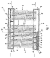
FIG. 1 is a sectional view of an exemplary embodiment of heat exchanger with a manifold having baffles according to the present disclosure; -
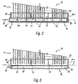
FIG. 2 is a close-up view of a first alternate exemplary embodiment of the manifold ofFIG. 1 ; -
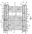
FIG. 3 is a close-up view of a second alternate exemplary embodiment of the manifold ofFIG. 1 ; -
FIG. 4 is a sectional view of an alternate heat exchanger with a manifold, -
FIG. 5 is a sectional view of an alternate exemplary embodiment of a heat exchanger with a manifold according to the present disclosure; and -
FIG. 6 illustrates an exemplary embodiment of a refrigeration circuit having a pair of heat exchangers according to the present disclosure. - Referring now to the figures and in particular to
FIG. 1 , an exemplary embodiment of parallel path heat exchanger according to the present disclosure is shown and is generally referred to byreference numeral 10.Heat exchanger 10 includes one ormore baffles 12 within one ormore manifolds baffles 12 are configured to limit the movement of the fluid along an axis (A) ofmanifold heat exchanger 10. - For purposes of clarity,
FIG. 1 illustratesheat exchanger 10 as a multipass heat exchanger having afirst pass 14 and asecond pass 16. Of course, it is contemplated by the present disclosure forbaffles 12 to find equal use with any parallel path heat exchanger having more than two passes. -
Heat exchanger 10 includes afirst manifold 18 and asecond manifold 20 that are in fluid communication with one another by way of a plurality ofparallel channels 22. In the illustrated embodiment,heat exchanger 10 is a micro-channel heat exchanger having a plurality of micro-channels 22. However, it is contemplated by the present disclosure forbaffles 12 to find equal use with any type of parallel path heatexchanger having channels 22 of any desired size. -
First manifold 18 includes a first partition 24-1 andsecond manifold 20 includes a second partition 24-2. Partitions 24-1, 24-2 are configured to separatemanifolds channels 22 intofirst pass 14 andsecond pass 16, respectively, along aline 26. Partition 24-1 dividesfirst manifold 18 into aninlet side 28 and anoutlet side 30. Similarly, partition 24-2 dividessecond manifold 20 into aninlet side 32 and anoutlet side 34. -
Heat exchanger 10 includes adistribution insert 36 withininlet side 28 offirst manifold 18. Further,heat exchanger 10 includes a collection insert 38 withinoutlet side 32 ofsecond manifold 20 and a distribution insert 40 withininlet side 34 ofsecond manifold 20. In the illustrated embodiment,collection insert 38 anddistribution insert 40 are shown as one unitary member. However, it is contemplated by the present disclosure for collection anddistribution inserts -
Heat exchanger 10 finds particular use with afluid 42, such as a refrigerant of a vapor-compression or air conditioning circuit.Fluid 42 can be a single-phase fluid or a two-phase fluid. Thus,fluid 42 traveling throughheat exchanger 10 can be in a vapor-phase and/or a liquid-phase. In the illustrated embodiment, the flow offluid 26 is represented by one or more directional arrows. -
Distribution insert 36 includes a plurality ofopenings 44 defined therein.Openings 44 place distribution insert 36 in fluid communication withinlet side 28 offirst manifold 18.Collection insert 38 includes a plurality ofopenings 46 defined therein.Openings 46 place collection insert 38 in fluid communication withoutlet side 32 ofsecond manifold 20.Distribution insert 40 includes a plurality ofopenings 48 defined therein.Openings 48 place distribution insert 40 in fluid communication withinlet side 34 ofsecond manifold 20. - During use,
fluid 42 entersheat exchanger 10 through distribution insert 36 withininlet side 28 offirst manifold 18. The fluid 42 is prevented from flowing frominlet side 28 tooutlet side 30 by partition 24-1. Rather,distribution insert 36 distributesfluid 42 intoinlet side 28 offirst manifold 18 throughopenings 44. - It has been determined by the present disclosure that
distribution insert 36 assists in passingfluid 42 in a substantially homogeneous state toinlet side 28 offirst manifold 18. More particularly, it has been determined thatdistribution insert 36 assists in mixingfluid 42 so that the fluid withininlet side 28 offirst manifold 18 is a substantially homogeneous mixture of liquid-phase fluid and vapor-phase fluid. -
Openings 44 are preferably of variable size to effectively mix and distribute fluid 42 flowing intoinlet side 28 offirst manifold 18.Openings 44 can have a dimension that can be uniform acrossdistribution insert 36, or the dimension of the openings can increase in size in a direction fromfirst pass 14 tosecond pass 16. For example,openings 44 can increase in dimension further downstream of the fluid flow path can achieve a greater degree of fluid distribution. - Within
inlet side 28, baffles 12 are configured to limit the movement offluid 42 within theinlet side 28 offirst manifold 18. More specifically, and without wishing to be bound by any particular theory, it has been determined by the present disclosure that the liquid and vapor phases offluid 42 can be separated by the fluidic forces withinheat exchanger 10 such that these forces can cause one of the two phases to be forced towards partition 24-1. This movement offluid 42 along the axis offirst manifold 18 towards partition 24-1 can be limited bybaffles 12. Thus, baffles 12 assist in mitigating maldistribution offluid 42 withinchannels 22 offirst pass 14. - In sum,
heat exchanger 10 includes a mixing device, illustrated asdistribution insert 36, to effectively mix fluid 42 as the fluid entersinlet side 28 so that both phases of the fluid are in a substantially homogeneous two-phase mixture withininlet side 28. Further,heat exchanger 10 includes one or more baffles 12 (two shown) to prevent the fluidic forces withininlet side 28 from separating the two phases from one another and forcing one of the two phases towards partition 24-1. In this manner, baffles 12 ensure thatfluid 42 enterschannels 22 offirst pass 14 in the substantially homogeneous two-phase mixture, which mitigates maldistribution of the fluid within the channels. -
Fluid 42 enterschannels 22 frominlet side 28 offirst manifold 18, flows through the channels and exits the channels intooutlet side 32 ofsecond manifold 20. Here,fluid 42 is prevented from flowing directly toinlet side 34 ofsecond manifold 20 by partition 24-2. - Rather, fluid 42 flows from
outlet side 32 to collection insert 38 throughopenings 46. Then, fluid 42 flows fromcollection insert 38 todistribution insert 40. In this manner, fluid 42 flows fromfirst pass 14 acrossline 26 intosecond pass 16. Next, fluid 42 flows fromdistribution insert 40 throughopenings 48 intoinlet side 34 ofsecond manifold 20. - It has been determined by the present disclosure that
collection insert 38 and distribution insert 40 assists in passingfluid 42 in a substantially homogeneous two-phase state toinlet side 34 ofsecond manifold 20. More specifically,collection insert 38 and distribution insert 40 eachmix fluid 42 as the fluid passes therethrough. - Baffles 12 within
second manifold 20 are configured to limit the movement offluid 42 withininlet side 34 along the axis (A) of the second manifold. Thus, baffles 12 can also assist in mitigating maldistribution offluid 42 withinchannels 22 ofsecond pass 16. -
Fluid 42 enterschannels 22 frominlet side 34 ofsecond manifold 20, flows through the channels and exits the channels intooutlet side 30 offirst manifold 18. In the illustrated embodiment whereheat exchanger 10 is a two-pass exchanger, fluid 42 flows out of the heat exchanger. However, it is contemplated by the present disclosure forheat exchanger 10 to have more than twopasses fluid 42 flowing fromsecond manifold 20 can enter a third pass (not shown) of channels. - An alternate embodiment of
heat exchanger 10 havingbaffles 12 is shown inFIG. 2 . For purposes of clarity, only relevant portions ofheat exchanger 10 are shown. Here,openings 44 indistribution insert 36 are illustrated directingfluid 42 in a direction substantially perpendicular (e.g., about ninety degrees) to the direction of flow throughchannels 22. By way of contrast,distribution insert 36 is illustrated inFIG. 1 havingopenings 44 directingfluid 42 in a direction substantially parallel (e.g., about zero degrees) to the direction of flow throughchannels 22. - As such, it is contemplated by the present disclosure for
heat exchanger 10 to havedistribution insert 36 withopenings 44 at any desired angle with respect to the direction of flow throughchannels 22. For example, it is contemplated forheat exchanger 10 to havedistribution insert 36 withopenings 44 at an angle such as zero degrees (FIG. 1 ), ninety degrees (FIG. 2 ), and angle there between, as well as any angle more than ninety degrees. Furthermore, it is contemplated for the angle ofopenings 44 to differ from one another such that some openings may have one angle, while other openings have a different angle. - Also shown in the embodiment of
FIG. 2 ,distribution insert 36 is shown as a closed ended tube having an end-cap 50 adjacent partition 24-1 , whereas the embodiment ofdistribution insert 36 shown inFIG. 1 is illustrated as an open ended tube connected to partition 24-1. - Referring now to
FIG. 3 , another exemplary embodiment ofheat exchanger 10 havingbaffles 12 is shown. Again, only the relevant portions ofheat exchanger 10 are shown. Here,distribution insert 36 is defined by afirst wall 52 and a second wall 54, where the first wall is independent offirst manifold 18, but the second wall is common with the first manifold. Further,distribution insert 36 is defined by partition 24-1. In contrast, the embodiments ofdistribution insert 36 shown inFIGS. 1 and2 have no walls in common withfirst manifold 18. - Referring now to
FIG. 4 , still anotherheat exchanger 10 havingbaffles 12 is shown. Thisheat exchanger 10, which falls outside the scope of the present invention, includes distributinginserts FIG. 1 . However, thisheat exchanger 10 lackscollection insert 38 withinoutlet side 32 ofsecond manifold 20 as inFIG. 1 . Rather,heat exchanger 10 illustrated inFIG. 4 includes an external collection-distributor 56. - External collection-
distributor 56 is in fluid communication withoutlet side 32 ofsecond manifold 20 via one or more ports 58 (only one shown). Further, external collection-distributor 56 is in fluid communication withinlet side 34 ofsecond manifold 20 via one or more ports 60 (three shown). - In this manner,
fluid 42 enterschannels 22 frominlet side 28 offirst manifold 18, flows through the channels and exits the channels intooutlet side 32 ofsecond manifold 20. Here,fluid 42 is prevented from flowing directly toinlet side 34 ofsecond manifold 20 by partition 24-2. - Rather, fluid 42 flows from
outlet side 32 to external collection-distributor 56 throughopenings 58. Then, fluid 42 flows through external collection-distributor 56 fromfirst pass 14 acrossline 26 intosecond pass 16. Next, fluid 42 flows from external collection-distributor 56 throughopenings 60 intodistribution insert 40, which further mixesfluid 42 as the fluid flows from the distribution insert throughopenings 48 intoinlet side 34 ofsecond manifold 20. As discussed above, baffles 12 withinsecond manifold 20 are configured to limit the movement offluid 42 along axis A of the second manifold. Thus, baffles 12 can also assist in mitigating maldistribution offluid 42 withinchannels 22 ofsecond pass 16. - External collection-
distributor 56 assists in passingfluid 42 in a substantially homogeneous state toinlet side 34 ofsecond manifold 20. The combination of external collection-distributor 56 along withdistribution insert 40 adds an additional mixing stage as compared to the embodiment ofFIG. 1 . Specifically, external collection-distributor 56 includes afirst portion 62 within first pass 14 (i.e., to the left of line 26) and a second portion 64 within second pass 16 (i.e., to the right of line 26). Here,first portion 62 functions in a manner similar to collection insert 38 ofFIG. 1 , while second portion 64 functions in a manner similar todistribution insert 40 ofFIG. 1 . Since the embodiment ofFIG. 4 includesfirst portion 62, second portion 64, anddistribution insert 40, this embodiment ofheat exchanger 10 provides one additional mixing stage offluid 42 as compared to the embodiment ofFIG. 1 . - Referring now to
FIG. 5 , another embodiment ofheat exchanger 10 is shown. - In this embodiment,
first manifold 18 includesinlet port 66 andoutlet port 68 that are configured so that the flow offluid 42 is in a direction substantially parallel (e.g., about zero degrees) to the flow of fluid throughchannels 22. By way of contrast,heat exchanger 10 illustrated inFIG. 1 havingports fluid 42 in a direction substantially perpendicular (e.g., about ninety degrees) to the direction of flow throughchannels 22. Furthermore, it is contemplated by the present disclosure forheat exchanger 10 to haveports channels 22. For example, it is contemplated forheat exchanger 10 to have one or bothports - Also illustrated in this embodiment,
first manifold 18 includescollection insert 38 withinoutlet side 30 of the first manifold.Collection insert 38 withinoutlet side 30 offirst manifold 18 functions as described with respect to collection insert 38 withinoutlet side 32 ofsecond manifold 20 of the embodiment ofFIG. 1 . Accordingly,heat exchanger 10 in the embodiment ofFIG. 5 provides for additional mixing offluid 42 before the fluid exits the heat exchanger. - Also illustrated in this embodiment,
heat exchanger 10 includes a second collection-distributor 70 atsecond manifold 20. Second collection-distributor 70 is in fluid communication withcollection insert 38 via one or more (only one shown)openings 72 and with distributinginsert 40 via one or more (only one shown)openings 74. In addition, partition 24-2 includes anextension 76 preventing direction fluid communication betweencollection insert 38 and distributinginsert 40. Thus,heat exchanger 10 in the embodiment ofFIG. 5 provides for additional mixing stages withinsecond manifold 20 as compared to the embodiment ofFIG. 1 . - Advantageously,
heat exchanger 10 finds use in any refrigeration circuit. For example, and referring now toFIG. 6 ,heat exchanger 10 is shown in use in arefrigeration circuit 80. Here,refrigeration circuit 80 has anevaporator 82 and acondenser 84. Advantageously,heat exchanger 10 can find use asevaporator 82, ascondenser 84, or both. -
Heat exchanger 10 can be arranged withincircuit 80 so that the plurality ofchannels 22 are arranged in any desired manner. In some embodiments,heat exchanger 10 can be arranged withincircuit 80 so thatchannels 22 are vertically arranged. In this manner,heat exchanger 10 can be arranged withincircuit 80 so that refrigerant 42 flows through the channels in an up-and-down manner. In other embodiments,heat exchanger 10 can be arranged withincircuit 80 so thatchannels 22 are horizontally arranged. In this manner,heat exchanger 10 can be arranged withincircuit 80 so that refrigerant flows throughchannels 22 in a side-to-side manner. -
Circuit 80 can find use in any vapor-compression device such as, but not limited to, an air conditioner, a heat pump, a dehumidifier, a refrigerator, a freezer, and others. For example,circuit 80 can find use in an air conditioner in a vehicle such as, but not limited to, an automobile, a truck, a ship, an airplane, and other mobile vehicles. Further,circuit 80 can find use in an air conditioner in a stationary conditioning device such as that used in a refrigerator, freezer, home air conditioner, or commercial air conditioner, a chiller unit, and others. - As described herein,
heat exchanger 10 includesparallel channels 22 in fluid communication with one another via a pair ofmanifolds heat exchanger 10 in a substantially uniform two-phase mixture. Advantageously,heat exchanger 10 also includes one ormore baffles 12 within one or more of themanifolds baffles 12 prevent movement offluid 22 along the axis of themanifolds channels 22. - It should also be noted that the terms "first", "second", "third", "upper", "lower", and the like may be used herein to modify various elements. These modifiers do not imply a spatial, sequential, or hierarchical order to the modified elements unless specifically stated.
Claims (12)
- A heat exchanger (10) for a fluid having a vapor-phase and a liquid-phase, comprising:a first manifold (18);a second manifold (20);a plurality of parallel channels (22) being in fluid communication with said first and second manifolds (18, 20);a first partition (24-1) defined within said first manifold (18) so that said plurality of parallel channels (22) define a first pass (14) in fluid communication with an inlet side (28) of said first manifold (18) and a second pass (16) in fluid communication with an outlet side (30) of said first manifold (18);a mixing device being configured to mix the fluid (42) flowing into said first manifold (18) so that the fluid (42) is a substantially homogeneous two-phase mixture of the vapor and liquid phases;one or more baffles (12) within said first manifold (18), said one or more baffles (12) being configured to ensure that the fluid (42) enters said plurality of parallel channels (22) as the substantially homogeneous two-phase mixture;a second partition (24-2) defined within said second manifold (20) so that said first pass (14) is in fluid communication with an inlet side (32) of said second manifold (20) and said second pass (16) is in fluid communication with an outlet side (34) of said second manifold (20), said inlet and outlet sides (32, 34) of said second manifold (20) being in fluid communication;a collection insert (38) within said inlet side (32) of said second manifold (20), said collection insert (38) configured to mix the fluid (42) flowing from said inlet side (32) of said second manifold (20) to form the substantially homogeneous two-phase mixture;a second distribution insert (40) within said outlet side (34) of said second manifold (20), said second distribution insert (40) being configured to mix the fluid (42) flowing into said outlet side (34) of said second manifold (20) from said inlet side (32) of said second manifold (20) so that the fluid (42) is the substantially homogeneous two-phase mixture; andone or more second baffles (12) within said outlet side (34) of said second manifold (20), said one or more baffles (12) being configured to ensure that the fluid (42) enters said plurality of parallel channels (22) of said second pass (16) as the substantially homogeneous two-phase mixture.
- The heat exchanger (10) as in claim 1, wherein the mixing device comprises a distributing insert (36) being disposed within said first manifold.(18) and wherein said distributing insert (36) comprises a plurality of openings (44) having a selected angle with respect to a fluid flow direction through said plurality of parallel channels (22).
- The heat exchanger (10) as in claim 1, wherein said collection insert (38) is in fluid communication with said second distribution insert (40).
- The heat exchanger (10) as in claim 1, wherein said collection insert (38) is internal to said second manifold (20), and further comprising a second collection-distributor (56) placing said collection insert (38) in fluid communication with said second distribution insert (40).
- The heat exchanger (10) as in claim 1 , wherein said inlet side (28) of said first manifold (18) is divided along an axis (26) from said outlet side (30) of said first manifold (18) by said first partition (24-1)
and wherein said first pass (14) of parallel channels (22) is in fluid communication with said inlet side (28) of said first manifold (18) and said second manifold (20) and said second pass (16) of parallel channels (22) is in fluid communication with said outlet side (30) of said first manifold (18) and said second manifold (20). - The heat exchanger (10) as in claim 5, wherein said mixing device comprises a distribution insert (36) within said inlet side (28) of said first manifold (18), said distribution insert (36) comprising a plurality of openings (44) being configured to mix the fluid (42) flowing into said inlet side (28) of said first manifold (18) so that the fluid (42) is a substantially homogeneous two-phase mixture of the vapor and liquid phases.
- The heat exchanger (10) as in claim 6, wherein said one or more baffles (12) are within said inlet side (28) of said first manifold (18).
- The heat exchanger (10) as in claim 6, wherein said distribution insert (36) comprises a plurality of openings having a dimension that is uniform across said distribution insert (36).
- The heat exchanger (10) as in claim 6, wherein said distribution insert (36) comprises a plurality of openings having a dimension that increase in size in a direction from said first pass (14) to said second pass (16).
- The heat exchanger (10) as in claim 1, wherein said inlet side (32) of said second manifold (20) is divided along said axis (26) from said outlet side (34) of said second manifold (20) by said second partition (24-2),
said one or more second baffles (12) within said outlet side (34) of said second manifold (20) being configured to prevent movement of the fluid (42) within said outlet side (34) of said second manifold (20) along said axis (26). - The heat exchanger (10) as in claim 1, wherein said first manifold (18) comprises an inlet port (66) and an outlet port (68), said inlet and outlet ports (66, 68) being configured so that flow of the fluid (42) through said inlet and outlet ports (66, 68) is in a direction substantially parallel to flow of the fluid (42) through said plurality of parallel channels (22).
- The heat exchanger (10) as in claim 1, wherein said first manifold (18) comprises an inlet port (66) and an outlet port (68), said inlet and outlet ports (66, 68) being configured so that flow of the fluid (42) through said inlet and outlet ports (66, 68) is in a direction substantially perpendicular to flow of the fluid (42) through said plurality of parallel channels (22).
Applications Claiming Priority (1)
| Application Number | Priority Date | Filing Date | Title |
|---|---|---|---|
| PCT/US2007/021858 WO2009048451A1 (en) | 2007-10-12 | 2007-10-12 | Heat exchangers having baffled manifolds |
Publications (3)
| Publication Number | Publication Date |
|---|---|
| EP2212639A1 EP2212639A1 (en) | 2010-08-04 |
| EP2212639A4 EP2212639A4 (en) | 2011-02-23 |
| EP2212639B1 true EP2212639B1 (en) | 2016-08-31 |
Family
ID=40549433
Family Applications (1)
| Application Number | Title | Priority Date | Filing Date |
|---|---|---|---|
| EP07839508.4A Not-in-force EP2212639B1 (en) | 2007-10-12 | 2007-10-12 | Heat exchanger having baffled manifolds |
Country Status (6)
| Country | Link |
|---|---|
| US (1) | US20100206535A1 (en) |
| EP (1) | EP2212639B1 (en) |
| CN (1) | CN101821577B (en) |
| DK (1) | DK2212639T3 (en) |
| ES (1) | ES2589319T3 (en) |
| WO (1) | WO2009048451A1 (en) |
Families Citing this family (62)
| Publication number | Priority date | Publication date | Assignee | Title |
|---|---|---|---|---|
| WO2009139998A2 (en) * | 2008-05-16 | 2009-11-19 | Carrier Corporation | Microchannel heat exchanger with enhanced refrigerant distribution |
| WO2015142615A1 (en) * | 2014-03-18 | 2015-09-24 | Carrier Corporation | Microchannel heat exchanger evaporator |
| US9267737B2 (en) | 2010-06-29 | 2016-02-23 | Johnson Controls Technology Company | Multichannel heat exchangers employing flow distribution manifolds |
| US9151540B2 (en) | 2010-06-29 | 2015-10-06 | Johnson Controls Technology Company | Multichannel heat exchanger tubes with flow path inlet sections |
| ITMI20100249U1 (en) * | 2010-07-16 | 2012-01-17 | Alfa Laval Corp Ab | HEAT EXCHANGE DEVICE WITH REFRIGERANT FLUID DISTRIBUTION SYSTEM |
| JP5740134B2 (en) * | 2010-10-25 | 2015-06-24 | 株式会社ケーヒン・サーマル・テクノロジー | Evaporator |
| JP5736164B2 (en) * | 2010-12-13 | 2015-06-17 | 株式会社ケーヒン・サーマル・テクノロジー | Evaporator |
| US9651317B2 (en) | 2011-01-21 | 2017-05-16 | Daikin Industries, Ltd. | Heat exchanger and air conditioner |
| KR101372096B1 (en) * | 2011-11-18 | 2014-03-07 | 엘지전자 주식회사 | A heat exchanger |
| JP5376010B2 (en) * | 2011-11-22 | 2013-12-25 | ダイキン工業株式会社 | Heat exchanger |
| US9551540B2 (en) | 2011-11-22 | 2017-01-24 | Daikin Industries, Ltd. | Heat exchanger |
| JP6075956B2 (en) * | 2012-01-31 | 2017-02-08 | 株式会社ケーヒン・サーマル・テクノロジー | Evaporator |
| JP6002421B2 (en) * | 2012-04-03 | 2016-10-05 | 株式会社ケーヒン・サーマル・テクノロジー | Heat exchanger |
| WO2013160956A1 (en) * | 2012-04-26 | 2013-10-31 | 三菱電機株式会社 | Heat-exchanger header and heat exchanger provided therewith |
| KR101826365B1 (en) * | 2012-05-04 | 2018-03-22 | 엘지전자 주식회사 | A heat exchanger |
| KR101409196B1 (en) * | 2012-05-22 | 2014-06-19 | 한라비스테온공조 주식회사 | Evaporator |
| KR101457585B1 (en) * | 2012-05-22 | 2014-11-03 | 한라비스테온공조 주식회사 | Evaporator |
| KR101878317B1 (en) * | 2012-05-22 | 2018-07-16 | 한온시스템 주식회사 | Evaporator |
| US9115938B2 (en) | 2012-06-20 | 2015-08-25 | Hamilton Sundstrand Corporation | Two-phase distributor |
| US20140123696A1 (en) | 2012-11-02 | 2014-05-08 | Hongseong KIM | Air conditioner and evaporator inlet header distributor therefor |
| KR20140116626A (en) * | 2013-03-25 | 2014-10-06 | 엘지전자 주식회사 | A heat exchanger |
| JP6140514B2 (en) * | 2013-04-23 | 2017-05-31 | 株式会社ケーヒン・サーマル・テクノロジー | Evaporator and vehicle air conditioner using the same |
| US10168084B2 (en) | 2013-05-10 | 2019-01-01 | Denso Corporation | Refrigerant evaporator |
| JP6131705B2 (en) * | 2013-05-10 | 2017-05-24 | 株式会社デンソー | Refrigerant evaporator |
| JP6213004B2 (en) * | 2013-07-18 | 2017-10-18 | 株式会社デンソー | Refrigerant evaporator |
| JP5761252B2 (en) * | 2013-05-22 | 2015-08-12 | ダイキン工業株式会社 | Heat exchanger |
| JP5741657B2 (en) | 2013-09-11 | 2015-07-01 | ダイキン工業株式会社 | Heat exchanger and air conditioner |
| JP5741658B2 (en) * | 2013-09-11 | 2015-07-01 | ダイキン工業株式会社 | Heat exchanger and air conditioner |
| JP6098451B2 (en) * | 2013-09-11 | 2017-03-22 | ダイキン工業株式会社 | Heat exchanger and air conditioner |
| JP6179399B2 (en) * | 2013-12-27 | 2017-08-16 | ダイキン工業株式会社 | Heat exchanger and air conditioner |
| JP6273838B2 (en) * | 2013-12-27 | 2018-02-07 | ダイキン工業株式会社 | Heat exchanger |
| US10443945B2 (en) * | 2014-03-12 | 2019-10-15 | Lennox Industries Inc. | Adjustable multi-pass heat exchanger |
| CN103983126B (en) * | 2014-05-28 | 2016-08-24 | 丹佛斯微通道换热器(嘉兴)有限公司 | Heat exchanger |
| US10184703B2 (en) * | 2014-08-19 | 2019-01-22 | Carrier Corporation | Multipass microchannel heat exchanger |
| US10197312B2 (en) * | 2014-08-26 | 2019-02-05 | Mahle International Gmbh | Heat exchanger with reduced length distributor tube |
| US11073314B2 (en) | 2015-05-27 | 2021-07-27 | Carrier Corporation | Mulitlevel distribution system for evaporator |
| EP3236189B1 (en) | 2015-11-30 | 2019-01-09 | Carrier Corporation | Heat exchanger for residential hvac applications |
| US10551099B2 (en) * | 2016-02-04 | 2020-02-04 | Mahle International Gmbh | Micro-channel evaporator having compartmentalized distribution |
| JP6656950B2 (en) * | 2016-02-29 | 2020-03-04 | 三菱重工サーマルシステムズ株式会社 | Heat exchangers and air conditioners |
| JP6145189B1 (en) * | 2016-02-29 | 2017-06-07 | 三菱重工業株式会社 | Heat exchanger and air conditioner |
| JP6611335B2 (en) * | 2016-02-29 | 2019-11-27 | 三菱重工サーマルシステムズ株式会社 | Heat exchanger and air conditioner |
| US10753688B2 (en) * | 2016-04-07 | 2020-08-25 | Mitsubishi Electric Corporation | Distributer, heat exchanger, and air-conditioning apparatus |
| KR102622732B1 (en) * | 2016-09-13 | 2024-01-10 | 삼성전자주식회사 | Heat exchanger, header for the same and manufacturing method thereof |
| KR102622735B1 (en) * | 2016-09-13 | 2024-01-09 | 삼성전자주식회사 | Heat exchanger |
| JP6862777B2 (en) * | 2016-11-11 | 2021-04-21 | 富士通株式会社 | Manifold and information processing equipment |
| WO2018181338A1 (en) * | 2017-03-27 | 2018-10-04 | ダイキン工業株式会社 | Heat exchanger and air-conditioning device |
| US11396002B2 (en) * | 2017-03-28 | 2022-07-26 | Uop Llc | Detecting and correcting problems in liquid lifting in heat exchangers |
| CN108662812B (en) * | 2017-03-31 | 2022-02-18 | 开利公司 | Flow balancer and evaporator having the same |
| EP3619492B1 (en) * | 2017-05-05 | 2023-07-26 | Carrier Corporation | Heat exchanger for heat pump applications |
| JP2020523546A (en) * | 2017-06-11 | 2020-08-06 | リヴニ,ツヴィ | Plate and shell heat exchange system with split manifold tubes |
| FR3068774B1 (en) * | 2017-07-06 | 2019-12-20 | Valeo Systemes Thermiques | DEVICE FOR THERMAL REGULATION OF AT LEAST ONE ELECTRICAL ENERGY STORAGE ELEMENT |
| CN110945300B (en) * | 2017-08-03 | 2022-07-22 | 三菱电机株式会社 | Refrigerant distributor, heat exchanger, and refrigeration cycle device |
| US20190212066A1 (en) * | 2018-01-11 | 2019-07-11 | Asia Vital Components Co., Ltd. | Water-cooling radiator assembly with internal horiziontal partition members and flow disturbing members |
| US11022382B2 (en) | 2018-03-08 | 2021-06-01 | Johnson Controls Technology Company | System and method for heat exchanger of an HVAC and R system |
| KR102601565B1 (en) * | 2018-12-14 | 2023-11-14 | 삼성전자주식회사 | Heat exchanger and air conditioner having the same |
| WO2020161761A1 (en) * | 2019-02-04 | 2020-08-13 | 三菱電機株式会社 | Heat exchanger and air-conditioner provided with same |
| JP6853867B2 (en) * | 2019-10-31 | 2021-03-31 | 三菱重工サーマルシステムズ株式会社 | Heat exchanger and air conditioner |
| IT202000024268A1 (en) * | 2020-10-14 | 2022-04-14 | Hudson Italiana Fbm | HEAD-TUBE SYSTEM FOR THE OPTIMIZED DISTRIBUTION OF THE FLUID IN AN AIR COOLING DEVICE |
| EP4015959B1 (en) * | 2020-12-15 | 2023-09-13 | Valeo Autosystemy Sp. z o.o. | Heat exchanger |
| US12066224B2 (en) * | 2022-06-03 | 2024-08-20 | Trane International Inc. | Evaporator charge management and method for controlling the same |
| JPWO2024121984A1 (en) * | 2022-12-07 | 2024-06-13 | ||
| EP4617605A1 (en) * | 2024-03-15 | 2025-09-17 | Carrier Corporation | Fluid distributor assembly for a heat exchanger |
Citations (1)
| Publication number | Priority date | Publication date | Assignee | Title |
|---|---|---|---|---|
| WO2008048505A2 (en) * | 2006-10-13 | 2008-04-24 | Carrier Corporation | Multi-pass heat exchangers having return manifolds with distributing inserts |
Family Cites Families (13)
| Publication number | Priority date | Publication date | Assignee | Title |
|---|---|---|---|---|
| US2555055A (en) * | 1948-05-14 | 1951-05-29 | Carrier Corp | Refrigerant distributor |
| GB715492A (en) * | 1951-12-19 | 1954-09-15 | Ici Ltd | Improvements in or relating to plate type heat exchangers |
| GB1509204A (en) * | 1974-11-14 | 1978-05-04 | Leslie Co | Self-cleaning heat exchanger circuit |
| DE3311579C2 (en) * | 1983-03-30 | 1985-10-03 | Süddeutsche Kühlerfabrik Julius Fr. Behr GmbH & Co. KG, 7000 Stuttgart | Heat exchanger |
| JP3017272B2 (en) | 1990-11-07 | 2000-03-06 | 株式会社ゼクセル | Heat exchanger |
| WO1997024562A1 (en) * | 1995-12-28 | 1997-07-10 | H-Tech, Inc. | Heater for fluids |
| US5865244A (en) * | 1997-03-25 | 1999-02-02 | Behr America, Inc. | Plastic header tank matrix and method of making same |
| US7163051B2 (en) * | 2003-08-28 | 2007-01-16 | Praxair Technology, Inc. | Heat exchanger distributor for multicomponent heat exchange fluid |
| EP1548380A3 (en) * | 2003-12-22 | 2006-10-04 | Hussmann Corporation | Flat-tube evaporator with micro-distributor |
| US7398819B2 (en) * | 2004-11-12 | 2008-07-15 | Carrier Corporation | Minichannel heat exchanger with restrictive inserts |
| AU2005326656B2 (en) * | 2005-02-02 | 2010-09-02 | Carrier Corporation | Heat exchanger with perforated plate in header |
| US7967060B2 (en) * | 2005-08-18 | 2011-06-28 | Parker-Hannifin Corporation | Evaporating heat exchanger |
| US20080023185A1 (en) * | 2006-07-25 | 2008-01-31 | Henry Earl Beamer | Heat exchanger assembly |
-
2007
- 2007-10-12 US US12/682,108 patent/US20100206535A1/en not_active Abandoned
- 2007-10-12 DK DK07839508.4T patent/DK2212639T3/en active
- 2007-10-12 CN CN2007801010526A patent/CN101821577B/en not_active Expired - Fee Related
- 2007-10-12 ES ES07839508.4T patent/ES2589319T3/en active Active
- 2007-10-12 WO PCT/US2007/021858 patent/WO2009048451A1/en not_active Ceased
- 2007-10-12 EP EP07839508.4A patent/EP2212639B1/en not_active Not-in-force
Patent Citations (1)
| Publication number | Priority date | Publication date | Assignee | Title |
|---|---|---|---|---|
| WO2008048505A2 (en) * | 2006-10-13 | 2008-04-24 | Carrier Corporation | Multi-pass heat exchangers having return manifolds with distributing inserts |
Also Published As
| Publication number | Publication date |
|---|---|
| DK2212639T3 (en) | 2016-09-19 |
| EP2212639A4 (en) | 2011-02-23 |
| HK1147798A1 (en) | 2011-08-19 |
| CN101821577A (en) | 2010-09-01 |
| EP2212639A1 (en) | 2010-08-04 |
| WO2009048451A1 (en) | 2009-04-16 |
| ES2589319T3 (en) | 2016-11-11 |
| CN101821577B (en) | 2012-08-22 |
| US20100206535A1 (en) | 2010-08-19 |
Similar Documents
| Publication | Publication Date | Title |
|---|---|---|
| DK2212639T3 (en) | Heat exchange with baffelforgreninger | |
| EP3203175B1 (en) | Heat exchanger and air conditioning apparatus | |
| EP3922941B1 (en) | Heat exchanger and air-conditioner provided with same | |
| EP2778595B1 (en) | Heat exchanger | |
| US9625214B2 (en) | Heat exchanger | |
| AU2006211653B2 (en) | Parallel flow heat exchanger for heat pump applications | |
| EP2079973B1 (en) | Multi-pass heat exchangers having return manifolds with distributing inserts | |
| CN107816824B (en) | heat exchanger | |
| CN105209846B (en) | Heat exchanger | |
| EP3045855B1 (en) | Heat exchanger and air conditioner | |
| EP3425320A1 (en) | Heat exchanger and air conditioner | |
| EP2927631B1 (en) | Heat exchanger, especially a condenser | |
| EP3203174B1 (en) | Heat exchanger header | |
| JPWO2019058540A1 (en) | Refrigerant distributor and air conditioner | |
| CN104364598B (en) | Refrigerant loop heat exchanger | |
| EP3059542A1 (en) | Laminated header, heat exchanger, and air-conditioner | |
| EP1809968A2 (en) | Parallel flow evaporator with shaped manifolds | |
| CN114729795A (en) | Heat exchanger | |
| US20100037652A1 (en) | Multi-channel heat exchanger with multi-stage expansion | |
| HK1147798B (en) | Heat exchangers having baffled manifolds | |
| US20220018614A1 (en) | Heat exchanger | |
| WO2025182138A1 (en) | Header distributor and heat exchanger | |
| WO2021214849A1 (en) | Air conditioner, freezer, and distributor | |
| JP2020085257A (en) | Header for heat exchanger, heat exchanger, outdoor unit, and air conditioner | |
| HK1138362B (en) | Multi-pass heat exchangers having return manifolds with distributing inserts |
Legal Events
| Date | Code | Title | Description |
|---|---|---|---|
| PUAI | Public reference made under article 153(3) epc to a published international application that has entered the european phase |
Free format text: ORIGINAL CODE: 0009012 |
|
| 17P | Request for examination filed |
Effective date: 20100510 |
|
| AK | Designated contracting states |
Kind code of ref document: A1 Designated state(s): AT BE BG CH CY CZ DE DK EE ES FI FR GB GR HU IE IS IT LI LT LU LV MC MT NL PL PT RO SE SI SK TR |
|
| AX | Request for extension of the european patent |
Extension state: AL BA HR MK RS |
|
| RIN1 | Information on inventor provided before grant (corrected) |
Inventor name: CONTI, TIZIANO Inventor name: MACRI, SALVATORE Inventor name: VERMA, PARMESH Inventor name: PARK, YOUNG, K. Inventor name: CHEN, ALEXANDER Inventor name: MUNOZ, JULES, RICARDO |
|
| DAX | Request for extension of the european patent (deleted) | ||
| A4 | Supplementary search report drawn up and despatched |
Effective date: 20110126 |
|
| 17Q | First examination report despatched |
Effective date: 20150318 |
|
| GRAP | Despatch of communication of intention to grant a patent |
Free format text: ORIGINAL CODE: EPIDOSNIGR1 |
|
| INTG | Intention to grant announced |
Effective date: 20160314 |
|
| GRAS | Grant fee paid |
Free format text: ORIGINAL CODE: EPIDOSNIGR3 |
|
| GRAA | (expected) grant |
Free format text: ORIGINAL CODE: 0009210 |
|
| AK | Designated contracting states |
Kind code of ref document: B1 Designated state(s): AT BE BG CH CY CZ DE DK EE ES FI FR GB GR HU IE IS IT LI LT LU LV MC MT NL PL PT RO SE SI SK TR |
|
| REG | Reference to a national code |
Ref country code: CH Ref legal event code: EP Ref country code: GB Ref legal event code: FG4D |
|
| REG | Reference to a national code |
Ref country code: NL Ref legal event code: FP |
|
| REG | Reference to a national code |
Ref country code: DK Ref legal event code: T3 Effective date: 20160913 |
|
| REG | Reference to a national code |
Ref country code: IE Ref legal event code: FG4D Ref country code: FR Ref legal event code: PLFP Year of fee payment: 10 |
|
| REG | Reference to a national code |
Ref country code: DE Ref legal event code: R096 Ref document number: 602007047760 Country of ref document: DE |
|
| REG | Reference to a national code |
Ref country code: AT Ref legal event code: REF Ref document number: 825373 Country of ref document: AT Kind code of ref document: T Effective date: 20161015 |
|
| REG | Reference to a national code |
Ref country code: ES Ref legal event code: FG2A Ref document number: 2589319 Country of ref document: ES Kind code of ref document: T3 Effective date: 20161111 |
|
| REG | Reference to a national code |
Ref country code: LT Ref legal event code: MG4D |
|
| REG | Reference to a national code |
Ref country code: AT Ref legal event code: MK05 Ref document number: 825373 Country of ref document: AT Kind code of ref document: T Effective date: 20160831 |
|
| PG25 | Lapsed in a contracting state [announced via postgrant information from national office to epo] |
Ref country code: FI Free format text: LAPSE BECAUSE OF FAILURE TO SUBMIT A TRANSLATION OF THE DESCRIPTION OR TO PAY THE FEE WITHIN THE PRESCRIBED TIME-LIMIT Effective date: 20160831 Ref country code: LT Free format text: LAPSE BECAUSE OF FAILURE TO SUBMIT A TRANSLATION OF THE DESCRIPTION OR TO PAY THE FEE WITHIN THE PRESCRIBED TIME-LIMIT Effective date: 20160831 |
|
| PG25 | Lapsed in a contracting state [announced via postgrant information from national office to epo] |
Ref country code: BE Free format text: LAPSE BECAUSE OF NON-PAYMENT OF DUE FEES Effective date: 20161031 Ref country code: GR Free format text: LAPSE BECAUSE OF FAILURE TO SUBMIT A TRANSLATION OF THE DESCRIPTION OR TO PAY THE FEE WITHIN THE PRESCRIBED TIME-LIMIT Effective date: 20161201 Ref country code: LV Free format text: LAPSE BECAUSE OF FAILURE TO SUBMIT A TRANSLATION OF THE DESCRIPTION OR TO PAY THE FEE WITHIN THE PRESCRIBED TIME-LIMIT Effective date: 20160831 Ref country code: AT Free format text: LAPSE BECAUSE OF FAILURE TO SUBMIT A TRANSLATION OF THE DESCRIPTION OR TO PAY THE FEE WITHIN THE PRESCRIBED TIME-LIMIT Effective date: 20160831 Ref country code: SE Free format text: LAPSE BECAUSE OF FAILURE TO SUBMIT A TRANSLATION OF THE DESCRIPTION OR TO PAY THE FEE WITHIN THE PRESCRIBED TIME-LIMIT Effective date: 20160831 |
|
| PG25 | Lapsed in a contracting state [announced via postgrant information from national office to epo] |
Ref country code: RO Free format text: LAPSE BECAUSE OF FAILURE TO SUBMIT A TRANSLATION OF THE DESCRIPTION OR TO PAY THE FEE WITHIN THE PRESCRIBED TIME-LIMIT Effective date: 20160831 Ref country code: EE Free format text: LAPSE BECAUSE OF FAILURE TO SUBMIT A TRANSLATION OF THE DESCRIPTION OR TO PAY THE FEE WITHIN THE PRESCRIBED TIME-LIMIT Effective date: 20160831 |
|
| PG25 | Lapsed in a contracting state [announced via postgrant information from national office to epo] |
Ref country code: PT Free format text: LAPSE BECAUSE OF FAILURE TO SUBMIT A TRANSLATION OF THE DESCRIPTION OR TO PAY THE FEE WITHIN THE PRESCRIBED TIME-LIMIT Effective date: 20170102 Ref country code: SK Free format text: LAPSE BECAUSE OF FAILURE TO SUBMIT A TRANSLATION OF THE DESCRIPTION OR TO PAY THE FEE WITHIN THE PRESCRIBED TIME-LIMIT Effective date: 20160831 Ref country code: BE Free format text: LAPSE BECAUSE OF FAILURE TO SUBMIT A TRANSLATION OF THE DESCRIPTION OR TO PAY THE FEE WITHIN THE PRESCRIBED TIME-LIMIT Effective date: 20160831 Ref country code: PL Free format text: LAPSE BECAUSE OF FAILURE TO SUBMIT A TRANSLATION OF THE DESCRIPTION OR TO PAY THE FEE WITHIN THE PRESCRIBED TIME-LIMIT Effective date: 20160831 Ref country code: CZ Free format text: LAPSE BECAUSE OF FAILURE TO SUBMIT A TRANSLATION OF THE DESCRIPTION OR TO PAY THE FEE WITHIN THE PRESCRIBED TIME-LIMIT Effective date: 20160831 Ref country code: BG Free format text: LAPSE BECAUSE OF FAILURE TO SUBMIT A TRANSLATION OF THE DESCRIPTION OR TO PAY THE FEE WITHIN THE PRESCRIBED TIME-LIMIT Effective date: 20161130 |
|
| REG | Reference to a national code |
Ref country code: CH Ref legal event code: PL |
|
| REG | Reference to a national code |
Ref country code: DE Ref legal event code: R097 Ref document number: 602007047760 Country of ref document: DE |
|
| PG25 | Lapsed in a contracting state [announced via postgrant information from national office to epo] |
Ref country code: IT Free format text: LAPSE BECAUSE OF FAILURE TO SUBMIT A TRANSLATION OF THE DESCRIPTION OR TO PAY THE FEE WITHIN THE PRESCRIBED TIME-LIMIT Effective date: 20160831 |
|
| PLBE | No opposition filed within time limit |
Free format text: ORIGINAL CODE: 0009261 |
|
| STAA | Information on the status of an ep patent application or granted ep patent |
Free format text: STATUS: NO OPPOSITION FILED WITHIN TIME LIMIT |
|
| REG | Reference to a national code |
Ref country code: DE Ref legal event code: R082 Ref document number: 602007047760 Country of ref document: DE Representative=s name: SCHMITT-NILSON SCHRAUD WAIBEL WOHLFROM PATENTA, DE |
|
| REG | Reference to a national code |
Ref country code: IE Ref legal event code: MM4A |
|
| PG25 | Lapsed in a contracting state [announced via postgrant information from national office to epo] |
Ref country code: LI Free format text: LAPSE BECAUSE OF NON-PAYMENT OF DUE FEES Effective date: 20161031 Ref country code: CH Free format text: LAPSE BECAUSE OF NON-PAYMENT OF DUE FEES Effective date: 20161031 |
|
| 26N | No opposition filed |
Effective date: 20170601 |
|
| PG25 | Lapsed in a contracting state [announced via postgrant information from national office to epo] |
Ref country code: LU Free format text: LAPSE BECAUSE OF NON-PAYMENT OF DUE FEES Effective date: 20161012 Ref country code: SI Free format text: LAPSE BECAUSE OF FAILURE TO SUBMIT A TRANSLATION OF THE DESCRIPTION OR TO PAY THE FEE WITHIN THE PRESCRIBED TIME-LIMIT Effective date: 20160831 |
|
| REG | Reference to a national code |
Ref country code: FR Ref legal event code: PLFP Year of fee payment: 11 |
|
| PG25 | Lapsed in a contracting state [announced via postgrant information from national office to epo] |
Ref country code: IE Free format text: LAPSE BECAUSE OF NON-PAYMENT OF DUE FEES Effective date: 20161012 |
|
| PG25 | Lapsed in a contracting state [announced via postgrant information from national office to epo] |
Ref country code: HU Free format text: LAPSE BECAUSE OF FAILURE TO SUBMIT A TRANSLATION OF THE DESCRIPTION OR TO PAY THE FEE WITHIN THE PRESCRIBED TIME-LIMIT; INVALID AB INITIO Effective date: 20071012 Ref country code: CY Free format text: LAPSE BECAUSE OF FAILURE TO SUBMIT A TRANSLATION OF THE DESCRIPTION OR TO PAY THE FEE WITHIN THE PRESCRIBED TIME-LIMIT Effective date: 20160831 |
|
| PG25 | Lapsed in a contracting state [announced via postgrant information from national office to epo] |
Ref country code: TR Free format text: LAPSE BECAUSE OF FAILURE TO SUBMIT A TRANSLATION OF THE DESCRIPTION OR TO PAY THE FEE WITHIN THE PRESCRIBED TIME-LIMIT Effective date: 20160831 Ref country code: IS Free format text: LAPSE BECAUSE OF FAILURE TO SUBMIT A TRANSLATION OF THE DESCRIPTION OR TO PAY THE FEE WITHIN THE PRESCRIBED TIME-LIMIT Effective date: 20160831 Ref country code: MT Free format text: LAPSE BECAUSE OF NON-PAYMENT OF DUE FEES Effective date: 20161031 Ref country code: MC Free format text: LAPSE BECAUSE OF FAILURE TO SUBMIT A TRANSLATION OF THE DESCRIPTION OR TO PAY THE FEE WITHIN THE PRESCRIBED TIME-LIMIT Effective date: 20160831 |
|
| REG | Reference to a national code |
Ref country code: FR Ref legal event code: PLFP Year of fee payment: 12 |
|
| PGFP | Annual fee paid to national office [announced via postgrant information from national office to epo] |
Ref country code: FR Payment date: 20180920 Year of fee payment: 12 |
|
| PGFP | Annual fee paid to national office [announced via postgrant information from national office to epo] |
Ref country code: NL Payment date: 20180924 Year of fee payment: 12 Ref country code: GB Payment date: 20180925 Year of fee payment: 12 Ref country code: DK Payment date: 20180921 Year of fee payment: 12 |
|
| PGFP | Annual fee paid to national office [announced via postgrant information from national office to epo] |
Ref country code: DE Payment date: 20180819 Year of fee payment: 12 |
|
| PGFP | Annual fee paid to national office [announced via postgrant information from national office to epo] |
Ref country code: ES Payment date: 20181105 Year of fee payment: 12 |
|
| REG | Reference to a national code |
Ref country code: DE Ref legal event code: R119 Ref document number: 602007047760 Country of ref document: DE |
|
| REG | Reference to a national code |
Ref country code: DK Ref legal event code: EBP Effective date: 20191031 |
|
| REG | Reference to a national code |
Ref country code: NL Ref legal event code: MM Effective date: 20191101 |
|
| PG25 | Lapsed in a contracting state [announced via postgrant information from national office to epo] |
Ref country code: DE Free format text: LAPSE BECAUSE OF NON-PAYMENT OF DUE FEES Effective date: 20200501 |
|
| PG25 | Lapsed in a contracting state [announced via postgrant information from national office to epo] |
Ref country code: NL Free format text: LAPSE BECAUSE OF NON-PAYMENT OF DUE FEES Effective date: 20191101 |
|
| GBPC | Gb: european patent ceased through non-payment of renewal fee |
Effective date: 20191012 |
|
| PG25 | Lapsed in a contracting state [announced via postgrant information from national office to epo] |
Ref country code: DK Free format text: LAPSE BECAUSE OF NON-PAYMENT OF DUE FEES Effective date: 20191031 Ref country code: GB Free format text: LAPSE BECAUSE OF NON-PAYMENT OF DUE FEES Effective date: 20191012 Ref country code: FR Free format text: LAPSE BECAUSE OF NON-PAYMENT OF DUE FEES Effective date: 20191031 |
|
| REG | Reference to a national code |
Ref country code: ES Ref legal event code: FD2A Effective date: 20210302 |
|
| PG25 | Lapsed in a contracting state [announced via postgrant information from national office to epo] |
Ref country code: ES Free format text: LAPSE BECAUSE OF NON-PAYMENT OF DUE FEES Effective date: 20191013 |