EP2212236B1 - Dispositif de fixation d'alimentation de liquide pour pistolet de pulvérisation - Google Patents
Dispositif de fixation d'alimentation de liquide pour pistolet de pulvérisation Download PDFInfo
- Publication number
- EP2212236B1 EP2212236B1 EP08842373.6A EP08842373A EP2212236B1 EP 2212236 B1 EP2212236 B1 EP 2212236B1 EP 08842373 A EP08842373 A EP 08842373A EP 2212236 B1 EP2212236 B1 EP 2212236B1
- Authority
- EP
- European Patent Office
- Prior art keywords
- container
- liquid
- plunger
- liquid supply
- spray gun
- Prior art date
- Legal status (The legal status is an assumption and is not a legal conclusion. Google has not performed a legal analysis and makes no representation as to the accuracy of the status listed.)
- Active
Links
- 239000007788 liquid Substances 0.000 title claims description 61
- 239000007921 spray Substances 0.000 title claims description 53
- 238000004891 communication Methods 0.000 claims description 4
- 239000012530 fluid Substances 0.000 claims description 4
- 238000000034 method Methods 0.000 claims description 4
- 230000002093 peripheral effect Effects 0.000 claims description 4
- 230000008878 coupling Effects 0.000 claims 3
- 238000010168 coupling process Methods 0.000 claims 3
- 238000005859 coupling reaction Methods 0.000 claims 3
- 238000006073 displacement reaction Methods 0.000 claims 3
- 230000000694 effects Effects 0.000 claims 1
- 239000003973 paint Substances 0.000 description 16
- 230000005484 gravity Effects 0.000 description 4
- 210000002445 nipple Anatomy 0.000 description 4
- 229910052751 metal Inorganic materials 0.000 description 3
- 239000002184 metal Substances 0.000 description 3
- 239000000203 mixture Substances 0.000 description 3
- 229920003023 plastic Polymers 0.000 description 3
- 229910052782 aluminium Inorganic materials 0.000 description 2
- XAGFODPZIPBFFR-UHFFFAOYSA-N aluminium Chemical compound [Al] XAGFODPZIPBFFR-UHFFFAOYSA-N 0.000 description 2
- 238000004140 cleaning Methods 0.000 description 2
- 239000002991 molded plastic Substances 0.000 description 2
- 239000004033 plastic Substances 0.000 description 2
- 238000005507 spraying Methods 0.000 description 2
- 230000009471 action Effects 0.000 description 1
- 239000000853 adhesive Substances 0.000 description 1
- 230000001070 adhesive effect Effects 0.000 description 1
- 239000000443 aerosol Substances 0.000 description 1
- 230000008859 change Effects 0.000 description 1
- 239000011248 coating agent Substances 0.000 description 1
- 238000000576 coating method Methods 0.000 description 1
- 229920001903 high density polyethylene Polymers 0.000 description 1
- 230000008676 import Effects 0.000 description 1
- 239000000463 material Substances 0.000 description 1
- 238000012986 modification Methods 0.000 description 1
- 230000004048 modification Effects 0.000 description 1
- 238000011017 operating method Methods 0.000 description 1
- 239000000049 pigment Substances 0.000 description 1
- 230000000630 rising effect Effects 0.000 description 1
- 239000002904 solvent Substances 0.000 description 1
- 229910001220 stainless steel Inorganic materials 0.000 description 1
- 239000010935 stainless steel Substances 0.000 description 1
- 239000000126 substance Substances 0.000 description 1
- 239000000758 substrate Substances 0.000 description 1
- 230000001960 triggered effect Effects 0.000 description 1
Images


Classifications
-
- B—PERFORMING OPERATIONS; TRANSPORTING
- B05—SPRAYING OR ATOMISING IN GENERAL; APPLYING FLUENT MATERIALS TO SURFACES, IN GENERAL
- B05B—SPRAYING APPARATUS; ATOMISING APPARATUS; NOZZLES
- B05B7/00—Spraying apparatus for discharge of liquids or other fluent materials from two or more sources, e.g. of liquid and air, of powder and gas
- B05B7/24—Spraying apparatus for discharge of liquids or other fluent materials from two or more sources, e.g. of liquid and air, of powder and gas with means, e.g. a container, for supplying liquid or other fluent material to a discharge device
- B05B7/2402—Apparatus to be carried on or by a person, e.g. by hand; Apparatus comprising containers fixed to the discharge device
- B05B7/2405—Apparatus to be carried on or by a person, e.g. by hand; Apparatus comprising containers fixed to the discharge device using an atomising fluid as carrying fluid for feeding, e.g. by suction or pressure, a carried liquid from the container to the nozzle
- B05B7/2408—Apparatus to be carried on or by a person, e.g. by hand; Apparatus comprising containers fixed to the discharge device using an atomising fluid as carrying fluid for feeding, e.g. by suction or pressure, a carried liquid from the container to the nozzle characterised by the container or its attachment means to the spray apparatus
- B05B7/241—Apparatus to be carried on or by a person, e.g. by hand; Apparatus comprising containers fixed to the discharge device using an atomising fluid as carrying fluid for feeding, e.g. by suction or pressure, a carried liquid from the container to the nozzle characterised by the container or its attachment means to the spray apparatus the container being pressurised
Definitions
- This invention relates generally to liquid supply apparatus for spray guns, and more particularly to an air pressure-assisted liquid supply apparatus attachable to a liquid input port of a spray gun.
- U.S. Patents 6,752,179 , 6,796,514 and 6,953,155 each describe a cup-like assembly for feeding liquid to the inlet port of such spray guns.
- the liquid to be sprayed is contained within a collapsible polymeric bag and the bag is, in turn, disposed in a rigid cup-like housing.
- An adapter designed to mate with the inlet connection of a particular spray gun is in fluid communication with the contents of the bag. When air under pressure is introduced in the space between the bag and the rigid housing, the bag is compressed forcing the liquid contents thereof out through the adapter and into the inlet port of the spray gun with which the liquid feeding assembly is attached.
- DE 8903436.8 depicts a spray gun with a container connectable to a spray cap having an air inlet bore for pressurising the container and a tube for conveying liquid from the container to a nozzle.
- the invention provides a liquid supply attachment according to claim 1 and a method of supplying liquid to an air-operated gun according to claim 15. More generally described herein is a rigid plastic or metal container having a cylindrical sidewall, a closed bottom and an open top with a removable cover closing the container's open top.
- the cover has first and second apertures formed through its thickness dimension.
- a generally rigid tube extends through the first aperture and extends toward, but short of, the container's closed bottom.
- a movable plunger is slidably disposed on the rigid tube and is dimensioned to wipe against the cylindrical sidewall of the container as the plunger is made to move from a first position proximate the removable top to a second position proximate the closed bottom such that the plunger's descent displaces liquid from the container through a lumen of the rigid tube.
- Means are provided for attaching the container to an air-operated spray gun such that liquid passing through the lumen of the rigid tube feeds the liquid to the spray gun.
- a connection is made between the spray gun and the second aperture in the cover allowing pressurized air to enter the container at a location above the movable plunger to thereby force the plunger downward against the surface of the liquid in the container.
- a disposable, single-use liner is provided that closely conforms to the bottom and cylindrical sidewall of the rigid container, the use of which facilitates clean-up of the container assembly following job completion or a desired paint color change.
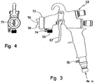
- FIG. 1a there is illustrated a liquid supply apparatus adapted for attachment to a commercially-available air-operated spray gun, such as shown in Figures 3 and 4 .
- the liquid in question may be a paint mixture, an adhesive or any one of a number of liquids to be applied as a coating on a substrate.
- the liquid will be referred to as spray paint that typically includes a pigment mixed with a volatile solvent that is of a viscosity permitting it to be applied as a fine spray when entrained in an air stream controlled by a pistol-like spray gun.
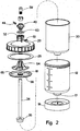
- the liquid supply attachment is indicated generally by numeral 10 and is seen to comprise a cylindrical cup 12 having a closed bottom end 14 and an open upper end 16. The lower end is shown as including a recessed portion 17 in Figure 1a .
- a base member 19 fits onto the bottom of the cup permitting the cup to better stand upright on a flat surface.
- the cup member 12 may be fabricated from a suitable rigid plastic or a metal, such as aluminum, and it is provided with external threads 18 located proximate its periphery at the upper end 16.
- the cup is preferably formed from a transparent plastic allowing the user to view the contents of the cup as a spray paint job progresses.
- Graduated markings as shown in Figure 2 may also be provided to indicate the volume of paint present at any given time.
- the open upper end of the cup member 12 is adapted to be closed by a cover member 20, which is designed to rest upon the upper edge surface of the cup 12 having an upper surface 24 and a downwardly depending cylindrical flange 26 that is internally threaded so as to mate with the threads 18 of the cup member 12.
- An O-ring or a flat gasket type seal 28 is placed between the cover member 20 and the upper edge of the cup member 12 so that when the cover member 20 is screwed down, a seal is created preventing escape of the liquid contents of the cup member 12.
- an optional molded plastic liner 30 disposed within the cup member 12 and closely adhering to the cylindrical sidewall 13 and the bottom wall 14 is an optional molded plastic liner 30 represented by a heavy black line in the drawing.
- the liner may be disposable after a single use which obviates the need for cleaning the interior wall surface of the cup 12 between successive uses. Because the liner 30 need not be collapsed, as in the cited 3M patents, it can be made to have a thicker wall if reuse is desired.
- the upper rim of the liner 30 is captured between the cover 20 and the upper edge of the cup member 12 and provides a seal that precludes spray paint or the like from finding its way between the inner wall of the cup member 12 and the outer wall of the liner 30.
- the cover member 20 has a frusto-conical dome shape that includes a central bore 32 into which is fitted a generally rigid or semi-rigid tube 34.
- the tube 34 extends toward, but ends just short of, the bottom wall 14 of the cup member 12 so that its lumen is not occluded by the bottom end 14.
- An optional basket-shaped screen filter 35 that fits within the recess 17 formed in the bottom end 14, is frictionally attached to the lower end of rigid tube 34. The filter precludes thickened globs of paint from entering the tube 34 and possibly occluding the spray gun's needle valve.
- the cover member 20 further includes a second bore 36 extending parallel to the bore 32 in which the tube 34 is made to fit. The bore 36 serves as an air passage through the thickness dimension of the cover 20, as will be further explained herein below.
- an adapter member 40 comprising a double lumen tube.
- the first lumen 42 extends the length of the adapter 40 and is in fluid communication with the lumen of the tube 34 that extends through the center of the dome 20.
- the second lumen of the adapter 40 is identified by numeral 46 and extends from an internally threaded opening 48 at the upper end of the adapter 40 to the bottom of the adapter where it is exposed to a chamber 50.
- a hose nipple 49 fits into threaded opening 48 whereby a short length of hose (not shown) is used to connect to the nipple 49 and to an air outlet 74 of a spray gun, as at 53 in Figure 3 .
- the air outlet fitting is located on the gun's handle, as at 75 in Figure 3 .
- an air compressor may be coupled to a port 51 leading to the chamber 50.
- Adapter 40 could also be designed to directly couple to a customized spray gun and include internal passages for both paint and compressed air. This would eliminate the need for external hose to deliver compressed air from the spray gun to the cup assembly.
- a plunger is slidingly mounted with respect to the outer wall of the tube 34 and is seen to include a molded plastic support member 54 to which is attached an elastomeric disk 56.
- the outer periphery of the elastomeric disk 56 is designed to be somewhat thinner than the portion thereof that is adhered to the support member 54 and is somewhat arcuately shaped to engage the inner wall of the container 12 or the optional liner 30 if one is used.
- the peripheral edge of disk 56 may be somewhat rounded as on an automobile windshield wiper so as to be able to move well in either an upward or downward direction.
- the portion 58 of the elastomeric disk 56 is also made thinner and curved so as to engage the outer wall of the tube 34 with a wiping action.
- the choice of materials for the plunger's elastomeric disk 56 may depend on its wear properties as well as the composition of the liquid to be sprayed so that there will be chemical compatibility.
- a one-way check valve can be used in the tubing between nipple 49 and port 74 or 75 on the gun to maintain pressure in the cup for most consistent spraying as the gun is triggered and released, or as the compressed air supply to the gun is removed and reapplied.
- port 51 exists to cover member 20 to allow a pressure relief device to be used to limit pressure in the cup assembly.
- Figure 2 the exploded view of the embodiment of Figures 1a-1c enables one to see the individual parts thereof.
- Figure 2 also shows with greater clarity the manner in which the elastomeric disk 56 is joined to the support member 54 and the way in which the elastomeric disk 56 is arranged to wipe against the tube 34 as the plunger member 52 is made to descend. It should be noted that the space above the inner curved portion of the elastomeric disk where it seals to the outer diameter of the tube 34 is exposed to air pressure above the plunger 52 to thereby provide a pressure-activated seal to the tube 34. Other seal arrangements in this area can also be made.
- a concentric annular protrusion 65 ( Figure 2 ) designed to engage and grip the peripheral edge of the support member 54.
- a similar protrusion 61 engages the support member 54 proximate its center opening.
- seal ring 63 that fits between the adapter 40 and the central stem of the cover 20 to preclude leakage at the joint between the two.
- the liner 30 in Figure 1a is absent. That is, the liner 30 is not essential, but the use thereof is a convenience that eliminates the necessity of cleaning the cup member 12 following each use thereof. The liner can simply be discarded.
- Figure 1a shows the liquid cup attachment for the spray gun where the plunger assembly 52 is elevated and the cup 12 is filled with paint or other liquid 67 to be dispensed via a spray gun.
- Figure 1b air pressure exerted on the upper surface of the plunger 52 has forced it down to a midway position in the cup 12, causing the paint to flow up through the lumen of the tube 34 and to thereby enter the spray gun where it mixes with the air stream to form an aerosol spray.
- Figure 1c shows the plunger fully displaced.
- the support member 54 has a tubular stem portion 72 whose height dimension is selected to provide a positive stop, preventing the elastomeric disk 56 from rising above the level of the cup's rim 16. As illustrated, the stem portion 72 will engage the cover's undersurface to prevent further upward rise of the plunger, maintaining the elastomeric disk 56 below the rim 16.
- the procedure may also be used with a partially filled container ( Fig. 1b ) to return the plunger to its topmost position so that the cup can be removed and the remaining contents emptied into a paint storage bucket.
- the cup is fabricated from a metal, such as aluminum or stainless steel such that the level of the contents remaining in the cup cannot be directly viewed, an indication of remaining liquid can be obtained by providing a graduated "dip-stick" that is attached to and moves with the support member 54 and that passes through a fluid-type diaphragm seal in the cover 20.
- the spray gun with the container attached can be held in any of a number of orientations with the base of the container pointed upward, downward or to the side during a spraying operation.
- the plunger forms an effective seal with respect to the container sidewall and the tubular member 34, the inside of the cover is not exposed to paint which facilitates clean-up following use.
- the cup can be replaced with a larger capacity container, such as a five gallon pressure pot, that would be connected with a length of hose to the hand-held spray gun liquid inlets and where a suitably designed air-pressure actuated plunger is provided that is made to slide down a tubular support in the pressure pot while wiping the interior wall of the pressure pot.
- a larger capacity container such as a five gallon pressure pot
Landscapes
- Nozzles (AREA)
Claims (16)
- Accessoire d'alimentation en liquide (10) pour un pistolet de pulvérisation pneumatique (53) comprenant :un contenant (12) pour un liquide (67) à pulvériser, le contenant ayant une chambre cylindrique avec une base fermée (14) et un dessus ouvert (16) avec un couvercle amovible (20) pour fermer le dessus ouvert du contenant, le couvercle étant traversé d'une ouverture (32) ;un tube rigide (34) s'étendant à travers l'ouverture (32) pour transporter le liquide (67) au pistolet de pulvérisation et s'étendant vers, mais s'arrêtant juste avant, la base du contenant (14) ; etun moyen (59) de fixation du contenant à un pistolet de pulvérisation pneumatique de sorte que le liquide passant à travers la lumière du tube rigide apporte le liquide au pistolet de pulvérisation ;caractérisé par un plongeur mobile (52) monté en coulissement sur le tube rigide et dimensionné pour frotter contre une paroi (13) définissant la chambre cylindrique lorsque le plongeur est amené à se déplacer d'une première position à proximité du dessus (16) à une seconde position à proximité de la base (14) et dans lequel le mouvement du plongeur déplace du liquide provenant du contenant (12) à travers une lumière du tube rigide (34).
- Accessoire d'alimentation en liquide selon la revendication 1, dans lequel le couvercle comporte une seconde ouverture (36) et de l'air pressurisé sort du pistolet de pulvérisation à travers une voie de passage (49) menant à la seconde ouverture (36, 48) pour déplacer le plongeur mobile (52) de la première position à la seconde position.
- Accessoire d'alimentation en liquide selon la revendication 2, dans lequel le moyen (59) de fixation du contenant (12) au pistolet de pulvérisation (53) comprend un adaptateur (40) ayant un premier trou traversant (42) en communication fluidique avec la lumière du tube rigide (34), et un second trou traversant (48) en communication fluidique avec la seconde ouverture (36), un couplage (59) adapté pour enclencher un orifice d'entrée (55) du pistolet de pulvérisation et un moyen (40) de couplage de la voie de passage (49) à la seconde ouverture.
- Accessoire d'alimentation en liquide selon la revendication 3, dans lequel l'adaptateur (40) est formé d'un seul tenant avec le couvercle amovible (20).
- Accessoire d'alimentation en liquide selon la revendication 1, dans lequel le plongeur (52) comprend un disque élastomérique (56) d'un diamètre légèrement supérieur au diamètre de la chambre cylindrique et un élément de support (54) apposé de façon concentrique sur une surface principale supérieure du disque élastomérique, l'élément de support comportant une tige tubulaire (72) adaptée pour y recevoir le tube rigide (34).
- Accessoire d'alimentation en liquide selon la revendication 5, dans lequel la dimension de hauteur de la tige tubulaire (72) est conçue pour enclencher le couvercle afin d'arrêter un déplacement vers le haut supplémentaire du plongeur (52) en un emplacement en dessous du dessus (16) du contenant.
- Accessoire d'alimentation en liquide selon la revendication 2, dans lequel la voie de passage (49) comporte un clapet de non-retour.
- Accessoire d'alimentation en liquide selon la revendication 1, dans lequel le contenant (12) comporte des filets de vis (18) à proximité du dessus ouvert (16) ; et comporte en outre un élément de bague annulaire ayant une bride cylindrique pendant vers le bas (26) qui est filetée à l'intérieur pour s'apparier avec lesdits filets de vis (18) à proximité du dessus ouvert (16) du contenant (12) pour maintenir le couvercle (20) en place.
- Accessoire d'alimentation en liquide selon la revendication 8, et comportant en outre un joint (28) disposé entre le couvercle (20) et le contenant (12) à proximité du dessus ouvert du contenant.
- Accessoire d'alimentation en liquide selon la revendication 1, dans lequel le plongeur (52) comprend un élément de support situé au centre (54) ayant un disque élastomérique (56) mis à adhérer à l'élément de support, une partie périphérique du disque étant d'épaisseur inférieure à une partie centrale qui est mise à adhérer à l'élément de support, la partie périphérique étant incurvée pour frotter efficacement contre un intérieur de la paroi latérale cylindrique (13) ou contre une doublure jetable (30) sur la paroi latérale cylindrique (13).
- Accessoire d'alimentation en liquide selon la revendication 10, dans lequel le disque élastomérique (56) comporte une partie d'épaisseur inférieure à la partie centrale et conformée pour frotter contre le tube rigide (34) pendant ledit déplacement vers le bas.
- Accessoire d'alimentation en liquide selon la revendication 3, dans lequel l'adaptateur (40) est arrimé au couvercle (20) en étant fileté sur le couvercle.
- Accessoire d'alimentation en liquide selon la revendication 1, et comportant en outre un élément de filtre (35) apposé autour d'une extrémité inférieure du tube rigide (34).
- Accessoire d'alimentation en liquide selon l'une quelconque des revendications 1 à 9, comprenant en outre :une doublure jetable (30) butant contre un intérieur de la paroi latérale cylindrique (13) et le fond (14) du contenant (12) pour protéger la paroi latérale intérieure et le fond du contenant d'une exposition au liquide à pulvériser, le plongeur étant disposé en coulissement sur le tube rigide et enclenchant la doublure jetable en ledit emplacement en dessous du couvercle.
- Procédé d'alimentation d'un pistolet de pulvérisation pneumatique (53) en un liquide à pulvériser comprenant les étapes de :(a) fourniture d'un pistolet de pulvérisation (53) ayant un orifice d'entrée de liquide (55) ;(b) fourniture d'un contenant (12) rempli d'un liquide (67) à pulvériser, le contenant ayant une base (14), une paroi latérale cylindrique (13), un dessus ouvert (16) et un couvercle (20) apposé de façon amovible sur le dessus ouvert où le couvercle comporte une première (32) et une seconde (36) ouverture à travers celui-ci avec un tube rigide (34) s'étendant dans la première ouverture (32) et menant à un emplacement à proximité de la base du contenant, le tube rigide supportant en coulissement un plongeur mobile (52) dessus où la périphérie du plongeur enclenche la paroi latérale cylindrique (13) du contenant ;(c) couplage du tube rigide (34) à l'orifice d'entrée de liquide (55) et de la seconde ouverture (36) à une source (74) d'un gaz pressurisé ; et(d) introduction du gaz pressurisé dans le contenant pour effectuer un déplacement du plongeur (52) vers la base et forcer la sortie du liquide du contenant à travers le tube rigide vers l'orifice d'entrée (55) du pistolet de pulvérisation.
- Procédé selon la revendication 15, et comportant en outre une étape de renvoi du plongeur (52) à une position de départ en réacheminant l'air pressurisé à travers le tube rigide (34) vers un espace entre la base fermée et le plongeur.
Applications Claiming Priority (2)
| Application Number | Priority Date | Filing Date | Title |
|---|---|---|---|
| US39007P | 2007-10-25 | 2007-10-25 | |
| PCT/US2008/012041 WO2009054986A1 (fr) | 2007-10-25 | 2008-10-23 | Dispositif de fixation d'alimentation de liquide pour pistolet de pulvérisation |
Publications (3)
| Publication Number | Publication Date |
|---|---|
| EP2212236A1 EP2212236A1 (fr) | 2010-08-04 |
| EP2212236A4 EP2212236A4 (fr) | 2013-07-31 |
| EP2212236B1 true EP2212236B1 (fr) | 2016-12-07 |
Family
ID=40579850
Family Applications (1)
| Application Number | Title | Priority Date | Filing Date |
|---|---|---|---|
| EP08842373.6A Active EP2212236B1 (fr) | 2007-10-25 | 2008-10-23 | Dispositif de fixation d'alimentation de liquide pour pistolet de pulvérisation |
Country Status (4)
| Country | Link |
|---|---|
| US (1) | US7878425B2 (fr) |
| EP (1) | EP2212236B1 (fr) |
| AU (1) | AU2008317355B2 (fr) |
| WO (1) | WO2009054986A1 (fr) |
Cited By (2)
| Publication number | Priority date | Publication date | Assignee | Title |
|---|---|---|---|---|
| DE102016125462A1 (de) * | 2016-12-22 | 2018-06-28 | Bert DELSARD | Vorrichtung zum pneumatischen Versprühen eines viskosen Fluids |
| DE102021120306A1 (de) | 2021-08-04 | 2023-02-09 | Sata Gmbh & Co. Kg | Pistolenkörper einer Farbspritzpistole sowie Farbspritzpistole |
Families Citing this family (37)
| Publication number | Priority date | Publication date | Assignee | Title |
|---|---|---|---|---|
| CA2595507C (fr) | 2004-12-16 | 2014-08-12 | Louis M. Gerson Co., Inc. | Coupelle d'alimentation de liquide et ensemble de revetement pour pistolets de pulverisation |
| ES2400161T3 (es) | 2006-06-20 | 2013-04-08 | Saint-Gobain Abrasives, Inc. | Conjunto de suministro de líquido |
| US11040360B2 (en) | 2006-06-20 | 2021-06-22 | Saint-Gobain Abrasives, Inc. | Liquid supply assembly |
| US20100314137A1 (en) * | 2009-06-16 | 2010-12-16 | Chemguard Inc. | Fire fighting foam proportioning devices and systems having improved low flow performance |
| WO2012068316A2 (fr) * | 2010-11-16 | 2012-05-24 | Saint-Gobain Abrasives, Inc. | Ensemble d'alimentation en liquide doté d'un revêtement intérieur amélioré |
| JP6087833B2 (ja) | 2010-11-23 | 2017-03-01 | アドバンスド テクノロジー マテリアルズ,インコーポレイテッド | ライナーベースの分注器 |
| US20120279613A1 (en) | 2011-05-06 | 2012-11-08 | Saint-Gobain Abrasifs | Paint Cup Assembly Support Structure |
| WO2012154619A2 (fr) * | 2011-05-06 | 2012-11-15 | Saint-Gobain Abrasives, Inc. | Ensemble de réservoir de peinture à joints d'étanchéité multiples |
| ES2739299T3 (es) | 2011-06-30 | 2020-01-30 | Saint Gobain Abrasives Inc | Conjunto de envase de pintura |
| CN103517765B (zh) | 2011-06-30 | 2017-09-12 | 萨塔有限两合公司 | 易清洗的喷枪、用于喷枪的附件及安装和拆卸方法 |
| US8844840B2 (en) * | 2011-12-20 | 2014-09-30 | Campbell Hausfeld/Scott Fetzer Company | Paint sprayer with paint container attachment apparatus |
| EP2797697B1 (fr) | 2011-12-30 | 2020-11-04 | Saint-Gobain Abrasives, Inc. | Ensemble godet de peinture convertible avec soupape d'entrée d'air |
| PL2969239T3 (pl) * | 2013-03-15 | 2017-08-31 | 3M Innovative Properties Company | Zespół dostarczania cieczy wspomagany ciśnieniowo |
| CN105188953B (zh) * | 2013-05-08 | 2018-06-22 | 固瑞克明尼苏达有限公司 | 用于手持式喷涂装置的涂料罐适配器 |
| DE102013212679A1 (de) * | 2013-06-28 | 2014-12-31 | Robert Bosch Gmbh | Fluidaufnahmevorrichtung |
| US9623390B2 (en) | 2013-10-16 | 2017-04-18 | X-Pert Paint Mixing Systems, Inc. | Canister |
| US10857553B2 (en) * | 2013-12-05 | 2020-12-08 | 3M Innovative Properties Company | Container for a spraying device |
| WO2015148448A1 (fr) * | 2014-03-24 | 2015-10-01 | Sio2 Medical Products, Inc. | Emballage pour solvants de haute pureté |
| CN105289870B (zh) | 2014-07-31 | 2019-09-24 | 萨塔有限两合公司 | 喷枪的制造方法、喷枪、喷枪本体以及盖 |
| CA159961S (en) | 2014-07-31 | 2015-07-17 | Sata Gmbh & Co Kg | Spray gun |
| WO2016069063A1 (fr) * | 2014-10-30 | 2016-05-06 | Graco Minnesota Inc. | Adaptateur de godet à peinture pour dispositif de pulvérisation à main |
| AU2016259755B2 (en) | 2015-05-12 | 2019-01-03 | Basf Coatings Gmbh | Safety and control device for pressurized containers, and pressurized container having such a safety and control device |
| DE102015006483A1 (de) * | 2015-05-22 | 2016-11-24 | Sata Gmbh & Co. Kg | Vorrichtung zur Beschichtung von Oberflächen, insbesondere von Farb- oder Lackoberflächen |
| DE102015006484A1 (de) | 2015-05-22 | 2016-11-24 | Sata Gmbh & Co. Kg | Düsenanordnung für eine Spritzpistole, insbesondere Farbspritzpistole und Spritzpistole, insbesondere Farbspritzpistole |
| DE102015210750A1 (de) * | 2015-06-12 | 2016-12-15 | Sms Elap Gmbh & Co. Kg | Adaptereinheit zum Zuführen von Druckluft in einen Behälter sowie Vorrichtung umfassend eine derartige Adaptereinheit |
| DE102015016474A1 (de) | 2015-12-21 | 2017-06-22 | Sata Gmbh & Co. Kg | Luftkappe und Düsenanordnung für eine Spritzpistole und Spritzpistole |
| US10973997B2 (en) * | 2016-01-25 | 2021-04-13 | Boehringer Ingelheim International Gmbh | Nebulizer |
| CN205995666U (zh) | 2016-08-19 | 2017-03-08 | 萨塔有限两合公司 | 喷枪及其扳机 |
| CN205966208U (zh) | 2016-08-19 | 2017-02-22 | 萨塔有限两合公司 | 风帽组件以及喷枪 |
| DE102017205160B3 (de) * | 2017-03-27 | 2018-02-22 | Sven Schlegel | Verschließbare Behälter-Anordnung |
| CN111032228A (zh) * | 2017-09-01 | 2020-04-17 | 巴斯夫涂料有限公司 | 计量和混合装置 |
| US11826771B2 (en) | 2018-08-01 | 2023-11-28 | Sata Gmbh & Co. Kg | Set of nozzles for a spray gun, spray gun system, method for embodying a nozzle module, method for selecting a nozzle module from a set of nozzles for a paint job, selection system and computer program product |
| DE102018118738A1 (de) | 2018-08-01 | 2020-02-06 | Sata Gmbh & Co. Kg | Grundkörper für eine Spritzpistole, Spritzpistolen, Spritzpistolen-Set, Verfahren zur Herstellung eines Grundkörpers für eine Spritzpistole und Verfahren zum Umrüsten einer Spritzpistole |
| DE102018118737A1 (de) | 2018-08-01 | 2020-02-06 | Sata Gmbh & Co. Kg | Düse für eine Spritzpistole, Düsensatz für eine Spritzpistole, Spritzpistolen und Verfahren zur Herstellung einer Düse für eine Spritzpistole |
| CN114273111B (zh) * | 2020-09-27 | 2023-05-30 | 湖南梨树园涂料有限公司 | 一种防水涂料施工用喷涂装置 |
| CN112916344B (zh) * | 2021-01-20 | 2022-07-26 | 中国人民解放军海军航空大学青岛校区 | 一种便携式涂层修复笔 |
| CA216837S (en) * | 2022-03-29 | 2023-09-15 | Qingdao Hanbo Plastic Tech Co Ltd | Paint spray for use in building |
Family Cites Families (21)
| Publication number | Priority date | Publication date | Assignee | Title |
|---|---|---|---|---|
| US888693A (en) * | 1907-09-09 | 1908-05-26 | Valentin Aranguren Y Bustinza | Paint-machine. |
| US3157360A (en) * | 1963-02-25 | 1964-11-17 | William L Heard | Spray gun having valved flexible liner |
| US3270920A (en) * | 1964-12-03 | 1966-09-06 | Charles G Nessler | Apparatus for pressure dispensing liquids |
| US4756481A (en) * | 1986-11-24 | 1988-07-12 | Theo Krebs Ag | Apparatus for spraying a flowable mass and including an airless spray gun |
| DE8903436U1 (fr) * | 1989-03-18 | 1989-05-11 | Fu, Lruen-Ching, Ta Li Hsiang, Taichung, Tw | |
| US4989787A (en) * | 1989-05-05 | 1991-02-05 | Nikkel Robert E | Liquid spray gun accessories |
| JPH0372973A (ja) * | 1989-08-11 | 1991-03-28 | Iwata Tosouki Kogyo Kk | 塗料供給量制御手段を有するスプレーガン |
| US5373971A (en) * | 1990-01-11 | 1994-12-20 | Laffy; Raoul | Aseptic container for holding and dispensing a sterile liquid or semi-liquid product |
| JP2916852B2 (ja) * | 1993-04-30 | 1999-07-05 | 株式会社タカハシ・プラスチック工業 | ピストン内蔵の圧力容器 |
| US5415352A (en) * | 1993-05-20 | 1995-05-16 | May; Michael W. | Spray system manifold apparatus and method |
| US5667142A (en) * | 1995-05-30 | 1997-09-16 | Newstripe, Inc. | Spray gun with removable supply line |
| US6820824B1 (en) * | 1998-01-14 | 2004-11-23 | 3M Innovative Properties Company | Apparatus for spraying liquids, disposable containers and liners suitable for use therewith |
| KR100335955B1 (ko) * | 1999-12-30 | 2002-05-10 | 이계안 | 도장막 보호용 코팅 시스템 |
| RU2228422C2 (ru) * | 2000-03-01 | 2004-05-10 | Иванников Владимир Иванович | Кавитирующее сопло |
| US6702203B2 (en) * | 2002-02-04 | 2004-03-09 | Wuu-Cheau Jou | Dual spray gun for painting and cleaning |
| US7153106B2 (en) * | 2003-01-16 | 2006-12-26 | R. Conrader Company | Air compressor unit inlet control |
| US7350723B2 (en) * | 2004-06-28 | 2008-04-01 | Just A Simple Thing, Inc | Cordless, self-contained, handheld spray gun |
| US7410106B2 (en) * | 2005-02-08 | 2008-08-12 | 3M Innovative Properties Company | Pressurized liquid supply assembly |
| US20070102458A1 (en) * | 2005-11-10 | 2007-05-10 | Spraying Systems Co. | Spray gun for dispensing precise small liquid volumes |
| DE502006004167D1 (de) * | 2006-02-11 | 2009-08-20 | Wagner Gmbh J | Spritzpistole mit angepasstem Vorratsbehälter |
| DE202006002469U1 (de) * | 2006-02-15 | 2006-04-13 | Mato Maschinen- Und Metallwarenfabrik Curt Matthaei Gmbh & Co Kg | Vorrichtung zum pneumatischen Versprühen eines viskosen Fluids |
-
2008
- 2008-10-23 WO PCT/US2008/012041 patent/WO2009054986A1/fr active Application Filing
- 2008-10-23 US US12/256,647 patent/US7878425B2/en active Active
- 2008-10-23 AU AU2008317355A patent/AU2008317355B2/en active Active
- 2008-10-23 EP EP08842373.6A patent/EP2212236B1/fr active Active
Cited By (2)
| Publication number | Priority date | Publication date | Assignee | Title |
|---|---|---|---|---|
| DE102016125462A1 (de) * | 2016-12-22 | 2018-06-28 | Bert DELSARD | Vorrichtung zum pneumatischen Versprühen eines viskosen Fluids |
| DE102021120306A1 (de) | 2021-08-04 | 2023-02-09 | Sata Gmbh & Co. Kg | Pistolenkörper einer Farbspritzpistole sowie Farbspritzpistole |
Also Published As
| Publication number | Publication date |
|---|---|
| WO2009054986A1 (fr) | 2009-04-30 |
| AU2008317355A1 (en) | 2009-04-30 |
| EP2212236A1 (fr) | 2010-08-04 |
| AU2008317355B2 (en) | 2012-05-31 |
| US7878425B2 (en) | 2011-02-01 |
| US20090108089A1 (en) | 2009-04-30 |
| EP2212236A4 (fr) | 2013-07-31 |
Similar Documents
| Publication | Publication Date | Title |
|---|---|---|
| EP2212236B1 (fr) | Dispositif de fixation d'alimentation de liquide pour pistolet de pulvérisation | |
| CA2502779C (fr) | Pistolet de pulverisation pourvu d'un element cupuliforme d'alimentation en liquide assistee par pression comprenant un contenant interne | |
| US6796514B1 (en) | Pre-packaged material supply assembly | |
| US10315787B2 (en) | Manual check valve for priming a collapsible fluid liner for a sprayer | |
| RU2362630C2 (ru) | Согласующийся резервуар пакетного типа для распылительного пистолета | |
| EP0814913B1 (fr) | Pulverisateur a pompe | |
| EP0678334B1 (fr) | Pistolet de pulvérisation avec réservoir sur sa partie supérieure | |
| US7380680B2 (en) | Fluid supply assembly | |
| TWI569880B (zh) | 用於具有一泵之一液體噴霧器之液體供應器、液體噴霧器及用於向一噴霧器提供具有可潰縮襯裡系統之一液體供應器之方法 | |
| US5415352A (en) | Spray system manifold apparatus and method | |
| RU2383395C2 (ru) | Резервуар для пистолета-распылителя с отверстием увеличенного размера для быстрого наполнения | |
| US4756481A (en) | Apparatus for spraying a flowable mass and including an airless spray gun | |
| JPS6353439B2 (fr) | ||
| US5474210A (en) | Fluid dispensing device |
Legal Events
| Date | Code | Title | Description |
|---|---|---|---|
| PUAI | Public reference made under article 153(3) epc to a published international application that has entered the european phase |
Free format text: ORIGINAL CODE: 0009012 |
|
| 17P | Request for examination filed |
Effective date: 20100525 |
|
| AK | Designated contracting states |
Kind code of ref document: A1 Designated state(s): AT BE BG CH CY CZ DE DK EE ES FI FR GB GR HR HU IE IS IT LI LT LU LV MC MT NL NO PL PT RO SE SI SK TR |
|
| AX | Request for extension of the european patent |
Extension state: AL BA MK RS |
|
| DAX | Request for extension of the european patent (deleted) | ||
| A4 | Supplementary search report drawn up and despatched |
Effective date: 20130628 |
|
| RIC1 | Information provided on ipc code assigned before grant |
Ipc: B05B 7/24 20060101ALI20130624BHEP Ipc: B67C 3/00 20060101AFI20130624BHEP |
|
| GRAP | Despatch of communication of intention to grant a patent |
Free format text: ORIGINAL CODE: EPIDOSNIGR1 |
|
| INTG | Intention to grant announced |
Effective date: 20160530 |
|
| GRAS | Grant fee paid |
Free format text: ORIGINAL CODE: EPIDOSNIGR3 |
|
| GRAA | (expected) grant |
Free format text: ORIGINAL CODE: 0009210 |
|
| STAA | Information on the status of an ep patent application or granted ep patent |
Free format text: STATUS: THE PATENT HAS BEEN GRANTED |
|
| AK | Designated contracting states |
Kind code of ref document: B1 Designated state(s): AT BE BG CH CY CZ DE DK EE ES FI FR GB GR HR HU IE IS IT LI LT LU LV MC MT NL NO PL PT RO SE SI SK TR |
|
| REG | Reference to a national code |
Ref country code: GB Ref legal event code: FG4D |
|
| REG | Reference to a national code |
Ref country code: CH Ref legal event code: EP Ref country code: AT Ref legal event code: REF Ref document number: 851512 Country of ref document: AT Kind code of ref document: T Effective date: 20161215 |
|
| REG | Reference to a national code |
Ref country code: IE Ref legal event code: FG4D |
|
| REG | Reference to a national code |
Ref country code: DE Ref legal event code: R096 Ref document number: 602008047795 Country of ref document: DE |
|
| PG25 | Lapsed in a contracting state [announced via postgrant information from national office to epo] |
Ref country code: LV Free format text: LAPSE BECAUSE OF FAILURE TO SUBMIT A TRANSLATION OF THE DESCRIPTION OR TO PAY THE FEE WITHIN THE PRESCRIBED TIME-LIMIT Effective date: 20161207 |
|
| REG | Reference to a national code |
Ref country code: NL Ref legal event code: FP |
|
| REG | Reference to a national code |
Ref country code: LT Ref legal event code: MG4D |
|
| PG25 | Lapsed in a contracting state [announced via postgrant information from national office to epo] |
Ref country code: NO Free format text: LAPSE BECAUSE OF FAILURE TO SUBMIT A TRANSLATION OF THE DESCRIPTION OR TO PAY THE FEE WITHIN THE PRESCRIBED TIME-LIMIT Effective date: 20170307 Ref country code: GR Free format text: LAPSE BECAUSE OF FAILURE TO SUBMIT A TRANSLATION OF THE DESCRIPTION OR TO PAY THE FEE WITHIN THE PRESCRIBED TIME-LIMIT Effective date: 20170308 Ref country code: LT Free format text: LAPSE BECAUSE OF FAILURE TO SUBMIT A TRANSLATION OF THE DESCRIPTION OR TO PAY THE FEE WITHIN THE PRESCRIBED TIME-LIMIT Effective date: 20161207 Ref country code: SE Free format text: LAPSE BECAUSE OF FAILURE TO SUBMIT A TRANSLATION OF THE DESCRIPTION OR TO PAY THE FEE WITHIN THE PRESCRIBED TIME-LIMIT Effective date: 20161207 |
|
| REG | Reference to a national code |
Ref country code: AT Ref legal event code: MK05 Ref document number: 851512 Country of ref document: AT Kind code of ref document: T Effective date: 20161207 |
|
| PG25 | Lapsed in a contracting state [announced via postgrant information from national office to epo] |
Ref country code: FI Free format text: LAPSE BECAUSE OF FAILURE TO SUBMIT A TRANSLATION OF THE DESCRIPTION OR TO PAY THE FEE WITHIN THE PRESCRIBED TIME-LIMIT Effective date: 20161207 Ref country code: ES Free format text: LAPSE BECAUSE OF FAILURE TO SUBMIT A TRANSLATION OF THE DESCRIPTION OR TO PAY THE FEE WITHIN THE PRESCRIBED TIME-LIMIT Effective date: 20161207 Ref country code: HR Free format text: LAPSE BECAUSE OF FAILURE TO SUBMIT A TRANSLATION OF THE DESCRIPTION OR TO PAY THE FEE WITHIN THE PRESCRIBED TIME-LIMIT Effective date: 20161207 |
|
| PG25 | Lapsed in a contracting state [announced via postgrant information from national office to epo] |
Ref country code: EE Free format text: LAPSE BECAUSE OF FAILURE TO SUBMIT A TRANSLATION OF THE DESCRIPTION OR TO PAY THE FEE WITHIN THE PRESCRIBED TIME-LIMIT Effective date: 20161207 Ref country code: RO Free format text: LAPSE BECAUSE OF FAILURE TO SUBMIT A TRANSLATION OF THE DESCRIPTION OR TO PAY THE FEE WITHIN THE PRESCRIBED TIME-LIMIT Effective date: 20161207 Ref country code: SK Free format text: LAPSE BECAUSE OF FAILURE TO SUBMIT A TRANSLATION OF THE DESCRIPTION OR TO PAY THE FEE WITHIN THE PRESCRIBED TIME-LIMIT Effective date: 20161207 Ref country code: CZ Free format text: LAPSE BECAUSE OF FAILURE TO SUBMIT A TRANSLATION OF THE DESCRIPTION OR TO PAY THE FEE WITHIN THE PRESCRIBED TIME-LIMIT Effective date: 20161207 Ref country code: IS Free format text: LAPSE BECAUSE OF FAILURE TO SUBMIT A TRANSLATION OF THE DESCRIPTION OR TO PAY THE FEE WITHIN THE PRESCRIBED TIME-LIMIT Effective date: 20170407 |
|
| PG25 | Lapsed in a contracting state [announced via postgrant information from national office to epo] |
Ref country code: IT Free format text: LAPSE BECAUSE OF FAILURE TO SUBMIT A TRANSLATION OF THE DESCRIPTION OR TO PAY THE FEE WITHIN THE PRESCRIBED TIME-LIMIT Effective date: 20161207 Ref country code: BG Free format text: LAPSE BECAUSE OF FAILURE TO SUBMIT A TRANSLATION OF THE DESCRIPTION OR TO PAY THE FEE WITHIN THE PRESCRIBED TIME-LIMIT Effective date: 20170307 Ref country code: PL Free format text: LAPSE BECAUSE OF FAILURE TO SUBMIT A TRANSLATION OF THE DESCRIPTION OR TO PAY THE FEE WITHIN THE PRESCRIBED TIME-LIMIT Effective date: 20161207 Ref country code: PT Free format text: LAPSE BECAUSE OF FAILURE TO SUBMIT A TRANSLATION OF THE DESCRIPTION OR TO PAY THE FEE WITHIN THE PRESCRIBED TIME-LIMIT Effective date: 20170407 Ref country code: BE Free format text: LAPSE BECAUSE OF FAILURE TO SUBMIT A TRANSLATION OF THE DESCRIPTION OR TO PAY THE FEE WITHIN THE PRESCRIBED TIME-LIMIT Effective date: 20161207 Ref country code: AT Free format text: LAPSE BECAUSE OF FAILURE TO SUBMIT A TRANSLATION OF THE DESCRIPTION OR TO PAY THE FEE WITHIN THE PRESCRIBED TIME-LIMIT Effective date: 20161207 |
|
| REG | Reference to a national code |
Ref country code: DE Ref legal event code: R097 Ref document number: 602008047795 Country of ref document: DE |
|
| PLBE | No opposition filed within time limit |
Free format text: ORIGINAL CODE: 0009261 |
|
| STAA | Information on the status of an ep patent application or granted ep patent |
Free format text: STATUS: NO OPPOSITION FILED WITHIN TIME LIMIT |
|
| REG | Reference to a national code |
Ref country code: FR Ref legal event code: PLFP Year of fee payment: 10 |
|
| 26N | No opposition filed |
Effective date: 20170908 |
|
| PG25 | Lapsed in a contracting state [announced via postgrant information from national office to epo] |
Ref country code: DK Free format text: LAPSE BECAUSE OF FAILURE TO SUBMIT A TRANSLATION OF THE DESCRIPTION OR TO PAY THE FEE WITHIN THE PRESCRIBED TIME-LIMIT Effective date: 20161207 Ref country code: SI Free format text: LAPSE BECAUSE OF FAILURE TO SUBMIT A TRANSLATION OF THE DESCRIPTION OR TO PAY THE FEE WITHIN THE PRESCRIBED TIME-LIMIT Effective date: 20161207 |
|
| PG25 | Lapsed in a contracting state [announced via postgrant information from national office to epo] |
Ref country code: MC Free format text: LAPSE BECAUSE OF FAILURE TO SUBMIT A TRANSLATION OF THE DESCRIPTION OR TO PAY THE FEE WITHIN THE PRESCRIBED TIME-LIMIT Effective date: 20161207 |
|
| REG | Reference to a national code |
Ref country code: CH Ref legal event code: PL |
|
| REG | Reference to a national code |
Ref country code: IE Ref legal event code: MM4A |
|
| PG25 | Lapsed in a contracting state [announced via postgrant information from national office to epo] |
Ref country code: CH Free format text: LAPSE BECAUSE OF NON-PAYMENT OF DUE FEES Effective date: 20171031 Ref country code: LU Free format text: LAPSE BECAUSE OF NON-PAYMENT OF DUE FEES Effective date: 20171023 Ref country code: LI Free format text: LAPSE BECAUSE OF NON-PAYMENT OF DUE FEES Effective date: 20171031 |
|
| PG25 | Lapsed in a contracting state [announced via postgrant information from national office to epo] |
Ref country code: MT Free format text: LAPSE BECAUSE OF NON-PAYMENT OF DUE FEES Effective date: 20171023 |
|
| REG | Reference to a national code |
Ref country code: FR Ref legal event code: PLFP Year of fee payment: 11 |
|
| PG25 | Lapsed in a contracting state [announced via postgrant information from national office to epo] |
Ref country code: IE Free format text: LAPSE BECAUSE OF NON-PAYMENT OF DUE FEES Effective date: 20171023 |
|
| PG25 | Lapsed in a contracting state [announced via postgrant information from national office to epo] |
Ref country code: HU Free format text: LAPSE BECAUSE OF FAILURE TO SUBMIT A TRANSLATION OF THE DESCRIPTION OR TO PAY THE FEE WITHIN THE PRESCRIBED TIME-LIMIT; INVALID AB INITIO Effective date: 20081023 |
|
| PG25 | Lapsed in a contracting state [announced via postgrant information from national office to epo] |
Ref country code: CY Free format text: LAPSE BECAUSE OF NON-PAYMENT OF DUE FEES Effective date: 20161207 |
|
| PG25 | Lapsed in a contracting state [announced via postgrant information from national office to epo] |
Ref country code: TR Free format text: LAPSE BECAUSE OF FAILURE TO SUBMIT A TRANSLATION OF THE DESCRIPTION OR TO PAY THE FEE WITHIN THE PRESCRIBED TIME-LIMIT Effective date: 20161207 |
|
| PGFP | Annual fee paid to national office [announced via postgrant information from national office to epo] |
Ref country code: NL Payment date: 20231026 Year of fee payment: 16 |
|
| PGFP | Annual fee paid to national office [announced via postgrant information from national office to epo] |
Ref country code: GB Payment date: 20231027 Year of fee payment: 16 |
|
| PGFP | Annual fee paid to national office [announced via postgrant information from national office to epo] |
Ref country code: FR Payment date: 20231025 Year of fee payment: 16 Ref country code: DE Payment date: 20231027 Year of fee payment: 16 |