EP2211967B1 - Dispositif médical allongé avec une pointe façonnable - Google Patents
Dispositif médical allongé avec une pointe façonnable Download PDFInfo
- Publication number
- EP2211967B1 EP2211967B1 EP08845941.7A EP08845941A EP2211967B1 EP 2211967 B1 EP2211967 B1 EP 2211967B1 EP 08845941 A EP08845941 A EP 08845941A EP 2211967 B1 EP2211967 B1 EP 2211967B1
- Authority
- EP
- European Patent Office
- Prior art keywords
- tubular member
- slots
- distal tip
- distal
- core wire
- Prior art date
- Legal status (The legal status is an assumption and is not a legal conclusion. Google has not performed a legal analysis and makes no representation as to the accuracy of the status listed.)
- Not-in-force
Links
Images


Classifications
-
- A—HUMAN NECESSITIES
- A61—MEDICAL OR VETERINARY SCIENCE; HYGIENE
- A61M—DEVICES FOR INTRODUCING MEDIA INTO, OR ONTO, THE BODY; DEVICES FOR TRANSDUCING BODY MEDIA OR FOR TAKING MEDIA FROM THE BODY; DEVICES FOR PRODUCING OR ENDING SLEEP OR STUPOR
- A61M25/00—Catheters; Hollow probes
- A61M25/01—Introducing, guiding, advancing, emplacing or holding catheters
- A61M25/09—Guide wires
- A61M2025/09058—Basic structures of guide wires
- A61M2025/09083—Basic structures of guide wires having a coil around a core
- A61M2025/09091—Basic structures of guide wires having a coil around a core where a sheath surrounds the coil at the distal part
-
- A—HUMAN NECESSITIES
- A61—MEDICAL OR VETERINARY SCIENCE; HYGIENE
- A61M—DEVICES FOR INTRODUCING MEDIA INTO, OR ONTO, THE BODY; DEVICES FOR TRANSDUCING BODY MEDIA OR FOR TAKING MEDIA FROM THE BODY; DEVICES FOR PRODUCING OR ENDING SLEEP OR STUPOR
- A61M25/00—Catheters; Hollow probes
- A61M25/01—Introducing, guiding, advancing, emplacing or holding catheters
- A61M25/09—Guide wires
- A61M2025/09108—Methods for making a guide wire
-
- A—HUMAN NECESSITIES
- A61—MEDICAL OR VETERINARY SCIENCE; HYGIENE
- A61M—DEVICES FOR INTRODUCING MEDIA INTO, OR ONTO, THE BODY; DEVICES FOR TRANSDUCING BODY MEDIA OR FOR TAKING MEDIA FROM THE BODY; DEVICES FOR PRODUCING OR ENDING SLEEP OR STUPOR
- A61M25/00—Catheters; Hollow probes
- A61M25/01—Introducing, guiding, advancing, emplacing or holding catheters
- A61M25/09—Guide wires
- A61M2025/09133—Guide wires having specific material compositions or coatings; Materials with specific mechanical behaviours, e.g. stiffness, strength to transmit torque
Definitions
- the present invention pertains to medical devices. More particularly, the present invention pertains to elongated intracorporeal medical devices including a tubular member connected with other structures.
- intracorporeal medical devices have been developed for medical use, for example, intravascular use. Some of these devices include guidewires, catheters, and the like. These devices are manufactured by any one of a variety of different manufacturing methods and may be used according to any one of a variety of methods.
- US 2001/0007922 A1 discloses a medical appliance having an elongated tubular shaft with a lumen extending therethrough and slots in the distal area for pressure medium entry into the lumen.
- a stiffening means in the form of an independent wire removably extends through the lumen with its proximal area extending proximally of the shaft.
- the proximal area of the shaft is affixed to a luer-lock comprising a housing with an inner cavity and a distal end forming a muff fixedly and tightly sealed on the proximal end of the shaft.
- the invention provides a medical device according to claim 1.
- Weight percent, percent by weight, wt%, wt-%, % by weight, and the like are synonyms that refer to the concentration of a substance as the weight of that substance divided by the weight of the composition and multiplied by 100.
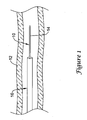
- Figure 1 is a plan view of an example medical device 10, for example a guidewire, disposed in a blood vessel 12.
- Guidewire 10 may include a distal section 14 that may be generally configured for probing within the anatomy of a patient.
- Guidewire 10 may be used for intravascular procedures.
- guidewire 10 may be used in conjunction with another medical device 16, which may take the form of a catheter, to treat and/or diagnose a medical condition.
- another medical device 16 which may take the form of a catheter, to treat and/or diagnose a medical condition.
- numerous other uses are known amongst clinicians for guidewires, catheters, and other similarly configured medical devices.
- medical device 10 is depicted in several of the drawings as a guidewire, it is not intended to be limited to just being a guidewire. Indeed, medical device 10 may take the form of any suitable guiding, diagnosing, or treating device (including catheters, endoscopic instruments, laparoscopic instruments, etc., and the like) and it may be suitable for use at essentially any location and/or body lumen within a patient. For example, medical device/guidewire 10 may be suitable for use in neurological interventions, coronary interventions, peripheral interventions, etc. As such, guidewire 10 may be appropriately sized for any given intervention.
- guidewire 10 may have an outside diameter of about 25.4 ⁇ m to 12.7 mm (0.001 to 0.5 inches) or about 38.1 ⁇ m to 1.27 mm (0015 to 0.05 inches) for neurological interventions; an outside diameter of about 25.4 ⁇ m to 12.7 mm (0.001 to 0.5 inches) or about 254 ⁇ m to 1.27 mm (0.01 to 0.05 inches) for coronary interventions; or an outside diameter of about 25.4 ⁇ m to 12.7 mm (0.01 to 0.5 inches) or about 508 ⁇ m to 1.27 mm (0.02 to 0.05 inches) for peripheral interventions.
- guidewire 10 may be a crossing guidewire that can be used to help a clinician cross an occlusion or stenosis in vessel 12.
- FIG. 2 is a partial cross-sectional view of guidewire 10.
- guidewire 10 may include a core member or core wire 18 and a tubular member 20 disposed over at least a portion of core wire 18.
- Core wire 18 may have a proximal section 22 and a distal section 24.
- Distal section 24 may include one or more tapers, tapered regions, steps, stepped regions, combinations thereof, or the like. At least some of these are described in more detail below.
- tubular member 20 is disposed over distal section 24 of core wire 18.
- Tubular member 20 and distal section 24, collectively, may define a distal tip 26 for guidewire 10.
- Distal tip 26 may further include a tip member 28, for example a solder ball distal tip, and a coil 30.
- Distal tip 26 may be generally configured to be shapeable - i.e., distal tip 26 may be configured to be plastically deformed into a desired shape for a particular intervention.
- a number of structural features may contribute to the shapeability of distal tip 26.
- the materials selected for core wire 18 and/or tubular member 20 may contribute to the overall shapeability of distal tip 26.
- the relative size and/or cross-sectional area of core wire 18 and/or tubular member 20 may also contribute to shapeability.
- distal tip 26 has a flexural rigidity (e.g., based on the materials selected, the size and/or shape of the components, or any one of a number of different factors).
- the flexural rigidity is understood to be the amount of force required to bend distal tip 26 into a curve, arc, bend, or the like.
- the flexural rigidity of distal tip 26 may be such that distal tip 26 will plastically deform when exposed to a force sufficient to cause about 2% or more strain on distal tip 26.
- the relative contribution of the core wire 18 and the tubular member 20 to the flexural rigidity of distal tip 26 may vary relative to the longitudinal position along distal tip 26. For example, adjacent to a proximal end 32 of distal tip 26, tubular member 20 may account for about 30% or less of the flexural rigidity of distal tip 26 and adjacent to a distal end 34 of distal tip 26, tubular member 20 may account for about 70% or more of the flexural rigidity of distal tip 26.
- adjacent to the proximal end 32 tubular member 20 may account for about 25% or less of the flexural rigidity of distal tip 26 and adjacent to the distal end 34 of distal tip 26 tubular member 20 may account for about 75% or more of the flexural rigidity of distal tip 26. In still other embodiments, adjacent to the proximal end 32 tubular member 20 may account for about 20% or less of the flexural rigidity of distal tip 26 and adjacent to the distal end 34 of distal tip 26 tubular member 20 may account for about 80% or more of the flexural rigidity of distal tip 26.
- adjacent to the proximal end 32 tubular member 20 may account for about 15% or less of the flexural rigidity of distal tip 26 and adjacent to the distal end 34 of distal tip 26 tubular member 20 may account for about 85% or more of the flexural rigidity of distal tip 26. In still other embodiments, adjacent to the proximal end 32 tubular member 20 may account for about 10% or less of the flexural rigidity of distal tip 26 and adjacent to the distal end 34 of distal tip 26 tubular member 20 may account for about 90% or more of the flexural rigidity of distal tip 26.
- tubular member 20 adjacent to the proximal end 32 tubular member 20 may account for about 5% or less of the flexural rigidity of distal tip 26 and adjacent to the distal end 34 of distal tip 26 tubular member 20 may account for about 95% or more of the flexural rigidity of distal tip 26.
- the overall contribution to the shapeability of distal tip 26 may be dominated by the shapeability characteristics of core wire 18.
- the overall contribution to the shapeability of distal tip 26 may be dominated by the shapeability characteristics of tubular member 20.
- the relative contribution transitions between the characteristics of core wire 18 and tubular member 20.
- This design feature may be achieved in a number of different ways including, for example, the selection of desirable materials for core wire 18 and/or tubular member 20 and by altering the total cross-sectional area (e.g., tapering) of core wire 18 and/or tubular member 20.
- this design feature may also be influenced by slots 36, which may be formed in tubular member 20 and are described in more detail below.
- core wire 18 (or at least the portion of core wire 18 that is part of distal tip 26, for example, distal portion 24) is made from a generally super-elastic material.
- core wire 18 may be made from a super-elastic nickel-titanium alloy.
- tubular member 20 may be from a relatively linear and/or non-super-elastic material such as nickel-chromium-molybdenum alloy (e.g., UNS: N06625 such as INCONEL® 625, UNS: N06022 such as HASTELLOY® C-22®, UNS: N10276 such as HASTELLOY® C276®, other HASTELLOY® alloys, and the like), platinum, stainless steel (such as 304V, 304L, 316LV stainless steel, mild steel, etc.), cobalt-chromium-molybdenum alloys (e.g., UNS: R30003 such as ELGILOY®, PHYNOX®, and the like), nickel-cobalt-chromium-molybdenum alloys (e.g., UNS: R30035 such as MP35-N® and the like), linear elastic and/or non-super-elastic nickel-titanium alloy, or the like.
- distal tip 26 may have shapeability characteristics that are more like those of core wire 18 (e.g., generally super-elastic) adjacent to proximal end 32 whereas adjacent to distal end 34, the shapeability characteristics of distal tip 26 may more closely resemble those of tubular member 20 (e.g., generally linear and/or non-super-elastic). Thus, distal tip 26 may generally become more "linear and/or non-super-elastic" along the length thereof until, eventually, distal tip 26 becomes generally shapeable.
- core wire 18 e.g., generally super-elastic
- core wire 18 and/or tubular member 20 may include stainless steel, one or more linear and/or non-super elastic materials, super elastic materials (e.g., super elastic nickel-titanium alloy), or combinations thereof.
- guidewire 10 may be manufactured with fewer structural components than other typical guidewires.
- guidewire 10 may be free of having a shaping structure or ribbon.
- guidewire 10 may be free of coil 30. These benefits may reduce the manufacturing costs of guidewire 10.
- linear and/or non-super-elastic materials may be utilized for tubular member 20, which may be less expensive than super-elastic materials, further cost savings can be realized during manufacturing.
- guidewire 10 may include a number of features, material compositions, and dimensions as well as variations on these characteristics. Below are listed some of these characteristics for illustration purposes. As will be appreciated, any values provided for dimensions herein are provided by way of example. Dimensions other than those provided below may be used without departing from the spirit of the invention.
- Core wire 18 may have a length of about 9 to about 125 inches. Distal section 24 may make up about 5 to 80 inches of that total length, the remainder being derived from proximal section 22.
- core wire 18 may include a number of tapers or tapered regions (e.g., tapered regions 36a/36b). Tapered regions 36a/36b may be formed by any one of a number of different techniques, for example, by centerless grinding methods, stamping methods, and the like.
- the centerless grinding technique may utilize an indexing system employing sensors (e.g., optical/reflective, magnetic) to avoid excessive grinding of the connection.
- centerless grinding technique may utilize a CBN or diamond abrasive grinding wheel that is well shaped and dressed to avoid grabbing core wire 18 during the grinding process.
- core wire 18 is centerless ground using a Royal Master HI-AC centerless grinder to define tapered regions 36a/36b.
- a generally constant outer diameter section 38a may extend between tapered regions 36a/36b. Located distal of tapered region 36b may be another generally constant outer diameter section 38b, followed by a shoulder or narrowed region 40 that may be narrowed abruptly (as shown) or more gently using any of the appropriate technique or methods described herein or any other suitable method. Narrowed region 40 may be coupled to tip member 28.
- Core wire 18 can have a solid cross-section, but in some embodiments, can have a hollow cross-section. In yet other embodiments, core wire 18 can include a combination of areas having solid cross-sections and hollow cross sections. Moreover, core wire 18, or portions thereof, can be made of rounded wire, flattened ribbon, or other such structures having various cross-sectional geometries. The cross-sectional geometries along the length of core wire 18 can also be constant or can vary. For example, Figure 2 depicts core wire 18 as having a round cross-sectional shape. It can be appreciated that other cross-sectional shapes or combinations of shapes may be utilized without departing from the spirit of the invention. For example, the cross-sectional shape of core wire 18 may be oval, rectangular, square, polygonal, and the like, or any suitable shape.
- Tubular member 20 may be bonded using any suitable technique to core wire 18.
- tubular member 20 may be bonded to core wire 18 and coil 32 at solder or laser bond 42 (which may alternatively be any of the other bonds described herein including a weld, braze, mechanical bond, adhesive bond, or the like, or any other suitable type of bond).
- solder or laser bond 42 which may alternatively be any of the other bonds described herein including a weld, braze, mechanical bond, adhesive bond, or the like, or any other suitable type of bond.
- portions or all of core wire 18 may include a solder coating that facilitates the joining of core wire 18 to other structures such as tubular member 20.
- tubular member 20 includes a plurality of cuts, apertures, and/or slots 36 formed therein.
- Slots 36 can be formed by methods such as micro-machining, saw-cutting (e.g., using a diamond grit embedded semiconductor dicing blade), laser cutting, electron discharge machining, grinding, milling, casting, molding, chemically etching or treating, or other known methods, and the like.
- the structure of the tubular member 20 is formed by cutting and/or removing portions of the tube to form slots 36.
- slots 36 are contemplated. In some embodiments, at least some, if not all of slots 36 are disposed at the same or a similar angle with respect to the longitudinal axis of the tubular member 20. As shown, slots 36 can be disposed at an angle that is perpendicular, or substantially perpendicular, and/or can be characterized as being disposed in a plane that is normal to the longitudinal axis of tubular member 20. However, in other embodiments, slots 36 can be disposed at an angle that is not perpendicular, and/or can be characterized as being disposed in a plane that is not normal to the longitudinal axis of tubular member 20.
- a group of one or more slots 36 may be disposed at different angles relative to another group of one or more slots 36.
- the distribution and/or configuration of slots 36 can also include, to the extent applicable, any of those disclosed in U.S. Pat. Publication No. US 2004/0181174 .
- Slots 36 may be provided to enhance the flexibility of tubular member 20 while still allowing for suitable torque transmission characteristics. Slots 36 may be formed such that one or more rings and/or turns interconnected by one or more segments and/or beams are formed in tubular member 20, and such rings and beams may include portions of tubular member 20 that remain after slots 36 are formed in the body of tubular member 20. Such an interconnected ring structure may act to maintain a relatively high degree of tortional stiffness, while maintaining a desired level of lateral flexibility. In some embodiments, some adjacent slots 36 can be formed such that they include portions that overlap with each other about the circumference of tubular member 20. In other embodiments, some adjacent slots 36 can be disposed such that they do not necessarily overlap with each other, but are disposed in a pattern that provides the desired degree of lateral flexibility.
- slots 36 can be arranged along the length of, or about the circumference of, tubular member 20 to achieve desired properties.
- adjacent slots 36, or groups of slots 36 can be arranged in a symmetrical pattern, such as being disposed essentially equally on opposite sides about the circumference of tubular member 20, or can be rotated by an angle relative to each other about the axis of tubular member 20.
- adjacent slots 36, or groups of slots 36 may be equally spaced along the length of tubular member 20, or can be arranged in an increasing or decreasing density pattern, or can be arranged in a non-symmetric or irregular pattern.
- tubular member 20 Other characteristics, such as slot size, slot shape and/or slot angle with respect to the longitudinal axis of tubular member 20, can also be varied along the length of tubular member 20 in order to vary the flexibility or other properties.
- portions of the tubular member such as a proximal section 26, or a distal section 28, or the entire tubular member 20, may not include any such slots 36.
- slots 36 may be formed in groups of two, three, four, five, or more slots 36, which may be located at substantially the same location along the axis of tubular member 20.
- groups of slots 36 there may be included slots 36 that are equal in size (i.e., span the same circumferential distance around tubular member 20).
- at least some slots 36 in a group are unequal in size (i.e., span a different circumferential distance around tubular member 20). Longitudinally adjacent groups of slots 36 may have the same or different configurations.
- some embodiments of tubular member 20 include slots 36 that are equal in size in a first group and then unequally sized in an adjacent group.
- the beams i.e., the portion of tubular member 20 remaining after slots 36 are formed therein
- the beams are offset from the center of tubular member 20.
- Some embodiments of tubular member 20 include only slots 36 that are aligned with the center of tubular member 20, only 42 that are offset from the center of tubular member 20, or slots 36 that are aligned with the center of tubular member 20 in a first group and offset from the center of tubular member 20 in another group.
- the amount of offset may vary depending on the depth (or length) of slots 36 and can include essentially any suitable distance.
- core wire 18, and/or tubular member 20, and the like may be made from a metal, metal alloy, polymer (some examples of which are disclosed below), a metal-polymer composite, combinations thereof, and the like, or any other suitable material.
- suitable metals and metal alloys include stainless steel, such as 304V, 304L, and 316LV stainless steel; mild steel; nickel-titanium alloy such as linear-elastic and/or super-elastic nitinol; other nickel alloys such as nickel-chromium-molybdenum alloys (e.g., UNS: N06625 such as INCONEL® 625, UNS: N06022 such as HASTELLOY® C-22®, UNS: N10276 such as HASTELLOY® C276®, other HASTELLOY® alloys, and the like), nickel-copper alloys (e.g., UNS: N04400 such as MONEL® 400, NICKELVAC® 400, NICORROS® 400, and the like), nickel-cobalt-chromium-molybdenum alloys (e.g., UNS: R30035 such as MP35-N® and the like), nickel-molybdenum alloys (e.g.,
- Linear elastic and/or non-super-elastic nitinol may be distinguished from super elastic nitinol in that the linear elastic and/or non-super-elastic nitinol does not display a substantial "superelastic plateau” or “flag region” in its stress/strain curve like super elastic nitinol does.
- linear elastic and/or non-super-elastic nitinol as recoverable strain increases, the stress continues to increase in a substantially linear, or a somewhat, but not necessarily entirely linear relationship until plastic deformation begins or at least in a relationship that is more linear that the super elastic plateau and/or flag region that may be seen with super elastic nitinol.
- linear elastic and/or non-super-elastic nitinol may also be termed "substantially" linear elastic and/or non-super-elastic nitinol.
- linear elastic and/or non-super-elastic nitinol may also be distinguishable from super elastic nitinol in that linear elastic and/or non-super-elastic nitinol may accept up to about 2-5% strain while remaining substantially elastic (e.g., before plastically deforming) whereas super elastic nitinol may accept up to about 8% strain before plastically deforming. Both of these materials can be distinguished from other linear elastic materials such as stainless steel (that can also can be distinguished based on its composition), which may accept only about 0.2-0.44% strain before plastically deforming.
- the linear elastic and/or non-super-elastic nickel-titanium alloy is an alloy that does not show any martensite/austenite phase changes that are detectable by DSC and DMTA analysis over a large temperature range.
- the mechanical bending properties of such material may therefore be generally inert to the effect of temperature over this very broad range of temperature.
- the mechanical bending properties of the linear elastic and/or non-super-elastic nickel-titanium alloy at ambient or room temperature are substantially the same as the mechanical properties at body temperature, for example, in that they do not display a super-elastic plateau and/or flag region.
- the linear elastic and/or non-super-elastic nickel-titanium alloy maintains its linear elastic and/or non-super-elastic characteristics and/or properties and has essentially no yield point.
- the linear elastic and/or non-super-elastic nickel-titanium alloy may be in the range of about 50 to about 60 weight percent nickel, with the remainder being essentially titanium. In some embodiments, the composition is in the range of about 54 to about 57 weight percent nickel.
- a suitable nickel-titanium alloy is FHP-NT alloy commercially available from Furukawa Techno Material Co. of Kanagawa, Japan. Some examples of nickel titanium alloys are disclosed in U.S. Patent Nos. 5,238,004 and 6,508,803 . Other suitable materials may include ULTANIUMTM (available from Neo-Metrics) and GUM METALTM (available from Toyota).
- a superelastic alloy for example a superelastic nitinol can be used to achieve desired properties.
- portions or all of core wire 18 and/or tubular member 20 may also be doped with, made of, or otherwise include a radiopaque material.
- Radiopaque materials are understood to be materials capable of producing a relatively bright image on a fluoroscopy screen or another imaging technique during a medical procedure. This relatively bright image aids the user of device 10 in determining its location.
- Some examples of radiopaque materials can include, but are not limited to, gold, platinum, palladium, tantalum, tungsten alloy, polymer material loaded with a radiopaque filler, and the like. Additionally, radiopaque marker bands and/or coils may be incorporated into the design of guidewire 10 to achieve the same result.
- a degree of MRI compatibility is imparted into guidewire 10.
- core wire 18 and/or tubular member 20, or other portions of the guidewire 10 may be made of a material that does not substantially distort the image and create substantial artifacts (artifacts are gaps in the image). Certain ferromagnetic materials, for example, may not be suitable because they may create artifacts in an MRI image.
- Core wire 18 and/or tubular member 20, or portions thereof may also be made from a material that the MRI machine can image.
- Some materials that exhibit these characteristics include, for example, tungsten, cobalt-chromium-molybdenum alloys (e.g., UNS: R30003 such as ELGILOY®, PHYNOX®, and the like), nickel-cobalt-chromium-molybdenum alloys (e.g., UNS: R30035 such as MP35-N® and the like), nitinol, and the like, and others.
- cobalt-chromium-molybdenum alloys e.g., UNS: R30003 such as ELGILOY®, PHYNOX®, and the like
- nickel-cobalt-chromium-molybdenum alloys e.g., UNS: R30035 such as MP35-N® and the like
- nitinol and the like, and others.
- the entire core wire 18 can be made of the same material along its length, or in some embodiments, can include portions or sections made of different materials that are joined, coupled, or otherwise connected together using a suitable connector.
- a suitable connector Essentially any suitable configuration and/or structure can be utilized for a connector including those connectors described in U.S. Patent Nos. 6,918,882 and 7,071,197 and/or in U.S. Patent Pub. No. US 2006-0122537 .
- the different portions of core wire 18 can be connected using welding (including laser welding), soldering, brazing, adhesive, or the like, or combinations thereof. These techniques can be utilized regardless of whether or not a connector is utilized.
- proximal section 22 and distal section 24 of core wire 18 may be formed of different materials, for example materials having different moduli of elasticity, resulting in a difference in flexibility.
- the material used to construct proximal section 22 can be relatively stiff for pushability and torqueability, and the material used to construct distal section 24 can be relatively flexible by comparison for better lateral trackability and steerability.
- proximal section 22 can be formed of straightened 304v stainless steel wire or ribbon (and/or linear and/or non-super-elastic nickel-titanium alloy) and distal section 24 can be formed of a straightened super elastic or linear elastic alloy, for example a nickel-titanium alloy wire or ribbon.
- a sheath or covering may be disposed over portions or all of core wire 18 and/or tubular member 20 that may define a generally smooth outer surface for guidewire 10. In other embodiments, however, such a sheath or covering may be absent from a portion of all of guidewire 10, such that tubular member 20 and/or core wire 18 may form the outer surface.
- the sheath may be made from a polymer or any other suitable material.
- suitable polymers may include polytetrafluoroethylene (PTFE), ethylene tetrafluoroethylene (ETFE), fluorinated ethylene propylene (FEP), polyoxymethylene (POM, for example, DELRIN® available from DuPont), polyether block ester, polyurethane, polypropylene (PP), polyvinylchloride (PVC), polyether-ester (for example, ARNITEL® available from DSM Engineering Plastics), ether or ester based copolymers (for example, butylene/poly(alkylene ether) phthalate and/or other polyester elastomers such as HYTREL® available from DuPont), polyamide (for example, DURETHAN® available from Bayer or CRISTAMID® available from Elf Atochem), elastomeric polyamides, block polyamide/ethers, polyether block amide (PEBA, for example available under the trade name PEBAX®), ethylene vinyl acetate copolymers (EVA), silicones
- the exterior surface of the guidewire 10 may be sandblasted, beadblasted, sodium bicarbonate-blasted, electropolished, etc.
- a coating for example a lubricious, a hydrophilic, a protective, or other type of coating may be applied over portions or all of the sheath, or in embodiments without a sheath over portion of core wire 18 and/or tubular member, or other portions of device 10.
- the sheath may comprise a lubricious, hydrophilic, protective, or other type of coating.
- Hydrophobic coatings such as fluoropolymers provide a dry lubricity which improves guidewire handling and device exchanges.
- Lubricious coatings improve steerability and improve lesion crossing capability.
- Suitable lubricious polymers are well known in the art and may include silicone and the like, hydrophilic polymers such as high-density polyethylene (HDPE), polytetrafluoroethylene (PTFE), polyarylene oxides, polyvinylpyrolidones, polyvinylalcohols, hydroxy alkyl cellulosics, algins, saccharides, caprolactones, and the like, and mixtures and combinations thereof.
- HDPE high-density polyethylene
- PTFE polytetrafluoroethylene
- polyarylene oxides polyvinylpyrolidones
- polyvinylalcohols polyvinylalcohols
- hydroxy alkyl cellulosics algins
- Hydrophilic polymers may be blended among themselves or with formulated amounts of water insoluble compounds (including some polymers) to yield coatings with suitable lubricity, bonding, and solubility.
- Some other examples of such coatings and materials and methods used to create such coatings can be found in U.S. Patent Nos. 6,139,510 and 5,772,609 .
- the coating and/or sheath may be formed, for example, by coating, extrusion, co-extrusion, interrupted layer co-extrusion (ILC), or fusing several segments end-to-end.
- the layer may have a uniform stiffness or a gradual reduction in stiffness from the proximal end to the distal end thereof. The gradual reduction in stiffness may be continuous as by ILC or may be stepped as by fusing together separate extruded tubular segments.
- the outer layer may be impregnated with a radiopaque filler material to facilitate radiographic visualization. Those skilled in the art will recognize that these materials can vary widely without deviating from the scope of the present invention.
- An example guidewire was constructed. This guidewire may be similar to guidewire
- the guidewire included a core wire having a distal section made from linear and/or non-super-elastic nickel titanium alloy.
- a tubular member having a plurality of slots formed therein was disposed over the distal section of the core wire.
- the tubular member was made of a nickel-chromium-molybdenum alloys (e.g., UNS: N06625 such as INCONEL® 625).
- a platinum coil was disposed within the tubular member adjacent to the core wire.
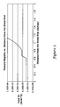
- the flexural rigidity (EI; where E is the modulus of elasticity and I is the second moment of inertia) was calculated. The data is presented in Table 1. Table 1. Flexural Rigidity in an Example Guidewire.
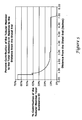
- the percent contribution of the tubular member to the total guidewire EL relative to the distance from the distal end of the guidewire in Example 1 was determined. The results are listed in Table 2. Table 2. Percent Contribution of the Tubular Member to the Total Guidewire EL Relative to the Distance from the Distal End of the Guidewire.
Claims (4)
- Dispositif médical (10), comprenant :un élément central longitudinal (18) présentant une section proximale (22) et une section distale (24) ;un élément tubulaire (20) disposé autour de la section distale (24) de l'élément central (18), l'élément tubulaire (20) présentant une pluralité de fentes (36) ménagés dans celui-ci ; etun élément d'embout (28) ;où la section distale (24) de l'élément central (18) et l'élément tubulaire (20) définissent un embout distal (26) pour le dispositif médical (10), ledit embout distal (26) présentant une extrémité proximale (32) et une extrémité distale (34) et étant exempt de ruban de formage ;ledit dispositif médical (10) étant caractérisé en ce que :l'élément central longitudinal (18) contient un alliage super-élastique nickel-titane ;l'élément tubulaire (20) contient un alliage nickel-chrome-molybdène ;la section distale (24) de l'élément central (18) étant reliée à l'élément d'embout (28) ;l'embout distal (26) présentant des caractéristiques super-élastiques dominées par les caractéristiques de formabilité de l'élément central (18) super-élastique dans la partie adjacente à l'extrémité proximale (32) de l'embout distal (26) ;l'embout distal (26) étant formable dans la partie adjacente à l'extrémité distale (34) de l'embout distal (26), etl'élément central (18) étant aminci entre l'extrémité proximale (32) de l'embout distal (26) et l'extrémité distale (34) de l'embout distal (26), de telle manière que l'embout distal (26) passe des caractéristiques super-élastiques de l'élément central (18) à la formabilité.
- Dispositif médical selon la revendication 1, où l'embout distal (26) est exempt d'enroulement.
- Dispositif médical selon la revendication 1 ou la revendication 2, où l'élément tubulaire (20) présente un axe longitudinal, où les fentes (36) ménagées dans l'élément tubulaire (20) sont agencées en groupes de fentes disposées au même emplacement longitudinal le long de l'axe longitudinal de l'élément tubulaire (20), et où chaque groupe comprend deux fentes.
- Dispositif médical selon l'une des revendications 1 à 3, où l'élément tubulaire (20) présente un axe longitudinal, où les fentes (36) ménagées dans l'élément tubulaire (20) sont agencées en groupes de fentes disposées au même emplacement longitudinal le long de l'axe longitudinal de l'élément tubulaire (20), et où chaque groupe comprend trois fentes.
Applications Claiming Priority (2)
| Application Number | Priority Date | Filing Date | Title |
|---|---|---|---|
| US11/934,647 US20090118675A1 (en) | 2007-11-02 | 2007-11-02 | Elongate medical device with a shapeable tip |
| PCT/US2008/081261 WO2009058705A2 (fr) | 2007-11-02 | 2008-10-27 | Dispositif médical allongé avec une pointe façonnable |
Publications (2)
| Publication Number | Publication Date |
|---|---|
| EP2211967A2 EP2211967A2 (fr) | 2010-08-04 |
| EP2211967B1 true EP2211967B1 (fr) | 2015-07-29 |
Family
ID=40588871
Family Applications (1)
| Application Number | Title | Priority Date | Filing Date |
|---|---|---|---|
| EP08845941.7A Not-in-force EP2211967B1 (fr) | 2007-11-02 | 2008-10-27 | Dispositif médical allongé avec une pointe façonnable |
Country Status (4)
| Country | Link |
|---|---|
| US (1) | US20090118675A1 (fr) |
| EP (1) | EP2211967B1 (fr) |
| JP (1) | JP5450432B2 (fr) |
| WO (1) | WO2009058705A2 (fr) |
Families Citing this family (20)
| Publication number | Priority date | Publication date | Assignee | Title |
|---|---|---|---|---|
| US10363389B2 (en) | 2009-04-03 | 2019-07-30 | Scientia Vascular, Llc | Micro-fabricated guidewire devices having varying diameters |
| EP2370237B1 (fr) | 2008-12-08 | 2015-12-02 | Jeff Christian | Machine de micro-découpe pour formation de découpes dans des produits |
| US11406791B2 (en) | 2009-04-03 | 2022-08-09 | Scientia Vascular, Inc. | Micro-fabricated guidewire devices having varying diameters |
| US9950137B2 (en) | 2009-04-03 | 2018-04-24 | Scientia Vascular, Llc | Micro-fabricated guidewire devices formed with hybrid materials |
| EP2453941B1 (fr) * | 2009-07-13 | 2016-12-14 | Cook Medical Technologies LLC | Dispositifs médicaux revêtus et procédés associés |
| JP2013523282A (ja) | 2010-03-31 | 2013-06-17 | ボストン サイエンティフィック サイムド,インコーポレイテッド | 曲げ剛性プロファイルを有するガイドワイヤ |
| US11298251B2 (en) | 2010-11-17 | 2022-04-12 | Abbott Cardiovascular Systems, Inc. | Radiopaque intraluminal stents comprising cobalt-based alloys with primarily single-phase supersaturated tungsten content |
| WO2012106628A1 (fr) | 2011-02-04 | 2012-08-09 | Boston Scientific Scimed, Inc. | Fils guides et procédés pour fabriquer et utiliser ceux-ci |
| US9072874B2 (en) | 2011-05-13 | 2015-07-07 | Boston Scientific Scimed, Inc. | Medical devices with a heat transfer region and a heat sink region and methods for manufacturing medical devices |
| US9724494B2 (en) | 2011-06-29 | 2017-08-08 | Abbott Cardiovascular Systems, Inc. | Guide wire device including a solderable linear elastic nickel-titanium distal end section and methods of preparation therefor |
| US10029076B2 (en) | 2012-02-28 | 2018-07-24 | Covidien Lp | Intravascular guidewire |
| JP2017513643A (ja) * | 2014-04-28 | 2017-06-01 | コーニンクレッカ フィリップス エヌ ヴェKoninklijke Philips N.V. | 血管内デバイスのためのプレドープされた固体基質 |
| US11052228B2 (en) | 2016-07-18 | 2021-07-06 | Scientia Vascular, Llc | Guidewire devices having shapeable tips and bypass cuts |
| US11207502B2 (en) | 2016-07-18 | 2021-12-28 | Scientia Vascular, Llc | Guidewire devices having shapeable tips and bypass cuts |
| US10821268B2 (en) | 2016-09-14 | 2020-11-03 | Scientia Vascular, Llc | Integrated coil vascular devices |
| US11452541B2 (en) | 2016-12-22 | 2022-09-27 | Scientia Vascular, Inc. | Intravascular device having a selectively deflectable tip |
| ES2966345T3 (es) | 2017-05-26 | 2024-04-22 | Scientia Vascular Inc | Dispositivo médico microfabricado con una disposición de corte no helicoidal |
| US11672957B2 (en) | 2017-07-26 | 2023-06-13 | Heraeus Medical Components Llc | Resilient tip and method |
| EP3717922A2 (fr) | 2017-12-03 | 2020-10-07 | Cook Medical Technologies, LLC | Guide-fil d'intervention compatible avec l'irm |
| US11305095B2 (en) | 2018-02-22 | 2022-04-19 | Scientia Vascular, Llc | Microfabricated catheter having an intermediate preferred bending section |
Family Cites Families (51)
| Publication number | Priority date | Publication date | Assignee | Title |
|---|---|---|---|---|
| US5144959A (en) * | 1989-08-15 | 1992-09-08 | C. R. Bard, Inc. | Catheter guidewire with varying radiopacity |
| US5095915A (en) * | 1990-03-19 | 1992-03-17 | Target Therapeutics | Guidewire with flexible distal tip |
| US5238004A (en) * | 1990-04-10 | 1993-08-24 | Boston Scientific Corporation | High elongation linear elastic guidewire |
| US5106455A (en) * | 1991-01-28 | 1992-04-21 | Sarcos Group | Method and apparatus for fabrication of micro-structures using non-planar, exposure beam lithography |
| US5329923A (en) * | 1991-02-15 | 1994-07-19 | Lundquist Ingemar H | Torquable catheter |
| CA2068584C (fr) * | 1991-06-18 | 1997-04-22 | Paul H. Burmeister | Guide metallique intravasculaire et mode de fabrication |
| CA2117088A1 (fr) * | 1991-09-05 | 1993-03-18 | David R. Holmes | Dispositif tubulaire flexible presentant des applications medicales |
| US5772609A (en) * | 1993-05-11 | 1998-06-30 | Target Therapeutics, Inc. | Guidewire with variable flexibility due to polymeric coatings |
| US5520194A (en) * | 1993-12-07 | 1996-05-28 | Asahi Intecc Co., Ltd. | Guide wire for medical purpose and manufacturing process of coil thereof |
| US6139510A (en) * | 1994-05-11 | 2000-10-31 | Target Therapeutics Inc. | Super elastic alloy guidewire |
| US5916178A (en) * | 1995-03-30 | 1999-06-29 | Medtronic, Inc. | Steerable high support guidewire with thin wall nitinol tube |
| EP0750879B1 (fr) * | 1995-06-29 | 2000-11-29 | Schneider (Europe) GmbH | Appareil médical pour la mesure de la pression dans un vaisseau sanguin |
| US6329069B1 (en) * | 1995-07-26 | 2001-12-11 | Surface Genesis, Inc. | Composite structure and devices made from same and method |
| US5746701A (en) * | 1995-09-14 | 1998-05-05 | Medtronic, Inc. | Guidewire with non-tapered tip |
| SE9504333D0 (sv) * | 1995-12-04 | 1995-12-04 | Pacesetter Ab | Styrtrådsenhet |
| US20030069522A1 (en) * | 1995-12-07 | 2003-04-10 | Jacobsen Stephen J. | Slotted medical device |
| US6004279A (en) * | 1996-01-16 | 1999-12-21 | Boston Scientific Corporation | Medical guidewire |
| US6440088B1 (en) * | 1996-05-24 | 2002-08-27 | Precision Vascular Systems, Inc. | Hybrid catheter guide wire apparatus and method |
| US6014919A (en) * | 1996-09-16 | 2000-01-18 | Precision Vascular Systems, Inc. | Method and apparatus for forming cuts in catheters, guidewires, and the like |
| EP0988081A1 (fr) * | 1997-06-04 | 2000-03-29 | Advanced Cardiovascular Systems, Inc. | Fil-guide orientable a support distal ameliore |
| US7455646B2 (en) * | 1997-06-04 | 2008-11-25 | Advanced Cardiovascular Systems, Inc. | Polymer coated guide wire |
| US7494474B2 (en) * | 1997-06-04 | 2009-02-24 | Advanced Cardiovascular Systems, Inc. | Polymer coated guidewire |
| US6245030B1 (en) * | 1998-03-04 | 2001-06-12 | C. R. Bard, Inc. | Flexible kink resistant, low friction guidewire with formable tip, and method for making same |
| US6508803B1 (en) * | 1998-11-06 | 2003-01-21 | Furukawa Techno Material Co., Ltd. | Niti-type medical guide wire and method of producing the same |
| US6402706B2 (en) * | 1998-12-30 | 2002-06-11 | Advanced Cardiovascular Systems, Inc. | Guide wire with multiple polymer jackets over distal and intermediate core sections |
| US6270476B1 (en) * | 1999-04-23 | 2001-08-07 | Cryocath Technologies, Inc. | Catheter |
| US6579246B2 (en) * | 1999-12-22 | 2003-06-17 | Sarcos, Lc | Coronary guidewire system |
| ES2274984T3 (es) * | 2001-07-05 | 2007-06-01 | Precision Vascular Systems, Inc. | Dispositivo medico de punta blanda que puede someterse a torsion y metodo para conformarlo. |
| US6918882B2 (en) * | 2001-10-05 | 2005-07-19 | Scimed Life Systems, Inc. | Guidewire with stiffness blending connection |
| CA2462335C (fr) * | 2001-10-05 | 2010-12-07 | Boston Scientific Limited | Fils-guides composites |
| US7018346B2 (en) * | 2001-12-18 | 2006-03-28 | Scimed Life Systems, Inc. | Guide wire with adjustable flexibility |
| US8257278B2 (en) * | 2002-05-14 | 2012-09-04 | Advanced Cardiovascular Systems, Inc. | Metal composite guide wire |
| JP4602080B2 (ja) * | 2002-07-25 | 2010-12-22 | ボストン サイエンティフィック リミテッド | 人体構造内を進行する医療用具 |
| US7914467B2 (en) * | 2002-07-25 | 2011-03-29 | Boston Scientific Scimed, Inc. | Tubular member having tapered transition for use in a medical device |
| US7058456B2 (en) * | 2002-08-09 | 2006-06-06 | Concentric Medical, Inc. | Methods and devices for changing the shape of a medical device |
| US7182735B2 (en) * | 2003-02-26 | 2007-02-27 | Scimed Life Systems, Inc. | Elongated intracorporal medical device |
| US20040167437A1 (en) * | 2003-02-26 | 2004-08-26 | Sharrow James S. | Articulating intracorporal medical device |
| US7001369B2 (en) * | 2003-03-27 | 2006-02-21 | Scimed Life Systems, Inc. | Medical device |
| US20050054952A1 (en) * | 2003-09-05 | 2005-03-10 | Scimed Life Systems, Inc. | Elongated medical device for intracorporal use |
| US7833175B2 (en) * | 2003-09-05 | 2010-11-16 | Boston Scientific Scimed, Inc. | Medical device coil |
| US7540845B2 (en) * | 2003-09-05 | 2009-06-02 | Boston Scientific Scimed, Inc | Medical device coil |
| US7785273B2 (en) * | 2003-09-22 | 2010-08-31 | Boston Scientific Scimed, Inc. | Guidewire with reinforcing member |
| US7824345B2 (en) * | 2003-12-22 | 2010-11-02 | Boston Scientific Scimed, Inc. | Medical device with push force limiter |
| US7416534B2 (en) * | 2004-06-22 | 2008-08-26 | Boston Scientific Scimed, Inc. | Medical device including actuator |
| US20060293612A1 (en) * | 2004-06-24 | 2006-12-28 | Boston Scientific Scimed, Inc. | Apparatus and method for treating occluded vasculature |
| US20070185415A1 (en) * | 2005-07-07 | 2007-08-09 | Ressemann Thomas V | Steerable guide wire with torsionally stable tip |
| US8043232B2 (en) * | 2005-08-05 | 2011-10-25 | Cook Medical Technologies Llc | High performance wire guide |
| US7867176B2 (en) * | 2005-12-27 | 2011-01-11 | Cordis Corporation | Variable stiffness guidewire |
| US20070167876A1 (en) * | 2006-01-17 | 2007-07-19 | Euteneuer Charles L | Occluding guidewire and methods |
| US8021311B2 (en) * | 2006-08-16 | 2011-09-20 | Boston Scientific Scimed, Inc. | Mechanical honing of metallic tubing for soldering in a medical device construction |
| US8419658B2 (en) * | 2006-09-06 | 2013-04-16 | Boston Scientific Scimed, Inc. | Medical device including structure for crossing an occlusion in a vessel |
-
2007
- 2007-11-02 US US11/934,647 patent/US20090118675A1/en not_active Abandoned
-
2008
- 2008-10-27 EP EP08845941.7A patent/EP2211967B1/fr not_active Not-in-force
- 2008-10-27 JP JP2010532167A patent/JP5450432B2/ja active Active
- 2008-10-27 WO PCT/US2008/081261 patent/WO2009058705A2/fr active Application Filing
Non-Patent Citations (1)
| Title |
|---|
| Special Materials Corp Inconel Alloy 625 * |
Also Published As
| Publication number | Publication date |
|---|---|
| WO2009058705A3 (fr) | 2011-03-24 |
| WO2009058705A2 (fr) | 2009-05-07 |
| JP5450432B2 (ja) | 2014-03-26 |
| EP2211967A2 (fr) | 2010-08-04 |
| JP2011517286A (ja) | 2011-06-02 |
| US20090118675A1 (en) | 2009-05-07 |
Similar Documents
| Publication | Publication Date | Title |
|---|---|---|
| EP2211967B1 (fr) | Dispositif médical allongé avec une pointe façonnable | |
| EP2670470B1 (fr) | Fils guides | |
| US8551020B2 (en) | Crossing guidewire | |
| US8795254B2 (en) | Medical devices with a slotted tubular member having improved stress distribution | |
| US8535243B2 (en) | Medical devices and tapered tubular members for use in medical devices | |
| US8137293B2 (en) | Guidewires including a porous nickel-titanium alloy | |
| US8376961B2 (en) | Micromachined composite guidewire structure with anisotropic bending properties | |
| US7914467B2 (en) | Tubular member having tapered transition for use in a medical device | |
| US8784337B2 (en) | Catheter with an improved flexural rigidity profile | |
| EP2183015B1 (fr) | Fils guides et procédés pour fabriquer des fils guides | |
| US20080262474A1 (en) | Medical device | |
| US20120209176A1 (en) | Balloon catheter | |
| US8002715B2 (en) | Medical device including a polymer sleeve and a coil wound into the polymer sleeve | |
| US20090118704A1 (en) | Interconnected ribbon coils, medical devices including an interconnected ribbon coil, and methods for manufacturing an interconnected ribbon coil | |
| US20230166079A1 (en) | Steerable elongate medical device |
Legal Events
| Date | Code | Title | Description |
|---|---|---|---|
| PUAI | Public reference made under article 153(3) epc to a published international application that has entered the european phase |
Free format text: ORIGINAL CODE: 0009012 |
|
| 17P | Request for examination filed |
Effective date: 20100526 |
|
| AK | Designated contracting states |
Kind code of ref document: A2 Designated state(s): AT BE BG CH CY CZ DE DK EE ES FI FR GB GR HR HU IE IS IT LI LT LU LV MC MT NL NO PL PT RO SE SI SK TR |
|
| AX | Request for extension of the european patent |
Extension state: AL BA MK RS |
|
| R17P | Request for examination filed (corrected) |
Effective date: 20100526 |
|
| R17D | Deferred search report published (corrected) |
Effective date: 20110324 |
|
| 17Q | First examination report despatched |
Effective date: 20110725 |
|
| DAX | Request for extension of the european patent (deleted) | ||
| RAP1 | Party data changed (applicant data changed or rights of an application transferred) |
Owner name: BOSTON SCIENTIFIC LIMITED |
|
| GRAP | Despatch of communication of intention to grant a patent |
Free format text: ORIGINAL CODE: EPIDOSNIGR1 |
|
| INTG | Intention to grant announced |
Effective date: 20150212 |
|
| GRAS | Grant fee paid |
Free format text: ORIGINAL CODE: EPIDOSNIGR3 |
|
| GRAA | (expected) grant |
Free format text: ORIGINAL CODE: 0009210 |
|
| AK | Designated contracting states |
Kind code of ref document: B1 Designated state(s): AT BE BG CH CY CZ DE DK EE ES FI FR GB GR HR HU IE IS IT LI LT LU LV MC MT NL NO PL PT RO SE SI SK TR |
|
| REG | Reference to a national code |
Ref country code: GB Ref legal event code: FG4D |
|
| REG | Reference to a national code |
Ref country code: CH Ref legal event code: EP |
|
| REG | Reference to a national code |
Ref country code: AT Ref legal event code: REF Ref document number: 738793 Country of ref document: AT Kind code of ref document: T Effective date: 20150815 |
|
| REG | Reference to a national code |
Ref country code: IE Ref legal event code: FG4D |
|
| REG | Reference to a national code |
Ref country code: DE Ref legal event code: R096 Ref document number: 602008039305 Country of ref document: DE |
|
| REG | Reference to a national code |
Ref country code: AT Ref legal event code: MK05 Ref document number: 738793 Country of ref document: AT Kind code of ref document: T Effective date: 20150729 |
|
| REG | Reference to a national code |
Ref country code: LT Ref legal event code: MG4D |
|
| REG | Reference to a national code |
Ref country code: NL Ref legal event code: FP |
|
| PG25 | Lapsed in a contracting state [announced via postgrant information from national office to epo] |
Ref country code: LV Free format text: LAPSE BECAUSE OF FAILURE TO SUBMIT A TRANSLATION OF THE DESCRIPTION OR TO PAY THE FEE WITHIN THE PRESCRIBED TIME-LIMIT Effective date: 20150729 Ref country code: GR Free format text: LAPSE BECAUSE OF FAILURE TO SUBMIT A TRANSLATION OF THE DESCRIPTION OR TO PAY THE FEE WITHIN THE PRESCRIBED TIME-LIMIT Effective date: 20151030 Ref country code: NO Free format text: LAPSE BECAUSE OF FAILURE TO SUBMIT A TRANSLATION OF THE DESCRIPTION OR TO PAY THE FEE WITHIN THE PRESCRIBED TIME-LIMIT Effective date: 20151029 Ref country code: FI Free format text: LAPSE BECAUSE OF FAILURE TO SUBMIT A TRANSLATION OF THE DESCRIPTION OR TO PAY THE FEE WITHIN THE PRESCRIBED TIME-LIMIT Effective date: 20150729 Ref country code: LT Free format text: LAPSE BECAUSE OF FAILURE TO SUBMIT A TRANSLATION OF THE DESCRIPTION OR TO PAY THE FEE WITHIN THE PRESCRIBED TIME-LIMIT Effective date: 20150729 |
|
| PG25 | Lapsed in a contracting state [announced via postgrant information from national office to epo] |
Ref country code: AT Free format text: LAPSE BECAUSE OF FAILURE TO SUBMIT A TRANSLATION OF THE DESCRIPTION OR TO PAY THE FEE WITHIN THE PRESCRIBED TIME-LIMIT Effective date: 20150729 Ref country code: ES Free format text: LAPSE BECAUSE OF FAILURE TO SUBMIT A TRANSLATION OF THE DESCRIPTION OR TO PAY THE FEE WITHIN THE PRESCRIBED TIME-LIMIT Effective date: 20150729 Ref country code: PT Free format text: LAPSE BECAUSE OF FAILURE TO SUBMIT A TRANSLATION OF THE DESCRIPTION OR TO PAY THE FEE WITHIN THE PRESCRIBED TIME-LIMIT Effective date: 20151130 Ref country code: IS Free format text: LAPSE BECAUSE OF FAILURE TO SUBMIT A TRANSLATION OF THE DESCRIPTION OR TO PAY THE FEE WITHIN THE PRESCRIBED TIME-LIMIT Effective date: 20151129 Ref country code: HR Free format text: LAPSE BECAUSE OF FAILURE TO SUBMIT A TRANSLATION OF THE DESCRIPTION OR TO PAY THE FEE WITHIN THE PRESCRIBED TIME-LIMIT Effective date: 20150729 Ref country code: SE Free format text: LAPSE BECAUSE OF FAILURE TO SUBMIT A TRANSLATION OF THE DESCRIPTION OR TO PAY THE FEE WITHIN THE PRESCRIBED TIME-LIMIT Effective date: 20150729 Ref country code: PL Free format text: LAPSE BECAUSE OF FAILURE TO SUBMIT A TRANSLATION OF THE DESCRIPTION OR TO PAY THE FEE WITHIN THE PRESCRIBED TIME-LIMIT Effective date: 20150729 |
|
| PG25 | Lapsed in a contracting state [announced via postgrant information from national office to epo] |
Ref country code: CZ Free format text: LAPSE BECAUSE OF FAILURE TO SUBMIT A TRANSLATION OF THE DESCRIPTION OR TO PAY THE FEE WITHIN THE PRESCRIBED TIME-LIMIT Effective date: 20150729 Ref country code: IT Free format text: LAPSE BECAUSE OF FAILURE TO SUBMIT A TRANSLATION OF THE DESCRIPTION OR TO PAY THE FEE WITHIN THE PRESCRIBED TIME-LIMIT Effective date: 20150729 Ref country code: SK Free format text: LAPSE BECAUSE OF FAILURE TO SUBMIT A TRANSLATION OF THE DESCRIPTION OR TO PAY THE FEE WITHIN THE PRESCRIBED TIME-LIMIT Effective date: 20150729 Ref country code: DK Free format text: LAPSE BECAUSE OF FAILURE TO SUBMIT A TRANSLATION OF THE DESCRIPTION OR TO PAY THE FEE WITHIN THE PRESCRIBED TIME-LIMIT Effective date: 20150729 Ref country code: EE Free format text: LAPSE BECAUSE OF FAILURE TO SUBMIT A TRANSLATION OF THE DESCRIPTION OR TO PAY THE FEE WITHIN THE PRESCRIBED TIME-LIMIT Effective date: 20150729 |
|
| REG | Reference to a national code |
Ref country code: DE Ref legal event code: R097 Ref document number: 602008039305 Country of ref document: DE |
|
| PG25 | Lapsed in a contracting state [announced via postgrant information from national office to epo] |
Ref country code: LU Free format text: LAPSE BECAUSE OF FAILURE TO SUBMIT A TRANSLATION OF THE DESCRIPTION OR TO PAY THE FEE WITHIN THE PRESCRIBED TIME-LIMIT Effective date: 20151027 Ref country code: RO Free format text: LAPSE BECAUSE OF FAILURE TO SUBMIT A TRANSLATION OF THE DESCRIPTION OR TO PAY THE FEE WITHIN THE PRESCRIBED TIME-LIMIT Effective date: 20150729 |
|
| REG | Reference to a national code |
Ref country code: CH Ref legal event code: PL |
|
| PLBE | No opposition filed within time limit |
Free format text: ORIGINAL CODE: 0009261 |
|
| STAA | Information on the status of an ep patent application or granted ep patent |
Free format text: STATUS: NO OPPOSITION FILED WITHIN TIME LIMIT |
|
| GBPC | Gb: european patent ceased through non-payment of renewal fee |
Effective date: 20151029 |
|
| PG25 | Lapsed in a contracting state [announced via postgrant information from national office to epo] |
Ref country code: MC Free format text: LAPSE BECAUSE OF FAILURE TO SUBMIT A TRANSLATION OF THE DESCRIPTION OR TO PAY THE FEE WITHIN THE PRESCRIBED TIME-LIMIT Effective date: 20150729 |
|
| 26N | No opposition filed |
Effective date: 20160502 |
|
| PG25 | Lapsed in a contracting state [announced via postgrant information from national office to epo] |
Ref country code: GB Free format text: LAPSE BECAUSE OF NON-PAYMENT OF DUE FEES Effective date: 20151029 Ref country code: CH Free format text: LAPSE BECAUSE OF NON-PAYMENT OF DUE FEES Effective date: 20151031 Ref country code: LI Free format text: LAPSE BECAUSE OF NON-PAYMENT OF DUE FEES Effective date: 20151031 |
|
| REG | Reference to a national code |
Ref country code: FR Ref legal event code: ST Effective date: 20160630 |
|
| PG25 | Lapsed in a contracting state [announced via postgrant information from national office to epo] |
Ref country code: SI Free format text: LAPSE BECAUSE OF FAILURE TO SUBMIT A TRANSLATION OF THE DESCRIPTION OR TO PAY THE FEE WITHIN THE PRESCRIBED TIME-LIMIT Effective date: 20150729 Ref country code: FR Free format text: LAPSE BECAUSE OF NON-PAYMENT OF DUE FEES Effective date: 20151102 |
|
| PG25 | Lapsed in a contracting state [announced via postgrant information from national office to epo] |
Ref country code: BE Free format text: LAPSE BECAUSE OF FAILURE TO SUBMIT A TRANSLATION OF THE DESCRIPTION OR TO PAY THE FEE WITHIN THE PRESCRIBED TIME-LIMIT Effective date: 20150729 |
|
| PG25 | Lapsed in a contracting state [announced via postgrant information from national office to epo] |
Ref country code: HU Free format text: LAPSE BECAUSE OF FAILURE TO SUBMIT A TRANSLATION OF THE DESCRIPTION OR TO PAY THE FEE WITHIN THE PRESCRIBED TIME-LIMIT; INVALID AB INITIO Effective date: 20081027 Ref country code: BG Free format text: LAPSE BECAUSE OF FAILURE TO SUBMIT A TRANSLATION OF THE DESCRIPTION OR TO PAY THE FEE WITHIN THE PRESCRIBED TIME-LIMIT Effective date: 20150729 |
|
| PG25 | Lapsed in a contracting state [announced via postgrant information from national office to epo] |
Ref country code: CY Free format text: LAPSE BECAUSE OF FAILURE TO SUBMIT A TRANSLATION OF THE DESCRIPTION OR TO PAY THE FEE WITHIN THE PRESCRIBED TIME-LIMIT Effective date: 20150729 |
|
| PG25 | Lapsed in a contracting state [announced via postgrant information from national office to epo] |
Ref country code: MT Free format text: LAPSE BECAUSE OF FAILURE TO SUBMIT A TRANSLATION OF THE DESCRIPTION OR TO PAY THE FEE WITHIN THE PRESCRIBED TIME-LIMIT Effective date: 20150729 Ref country code: TR Free format text: LAPSE BECAUSE OF FAILURE TO SUBMIT A TRANSLATION OF THE DESCRIPTION OR TO PAY THE FEE WITHIN THE PRESCRIBED TIME-LIMIT Effective date: 20150729 |
|
| PGFP | Annual fee paid to national office [announced via postgrant information from national office to epo] |
Ref country code: NL Payment date: 20191014 Year of fee payment: 12 Ref country code: IE Payment date: 20191010 Year of fee payment: 12 Ref country code: DE Payment date: 20191015 Year of fee payment: 12 |
|
| REG | Reference to a national code |
Ref country code: DE Ref legal event code: R119 Ref document number: 602008039305 Country of ref document: DE |
|
| REG | Reference to a national code |
Ref country code: NL Ref legal event code: MM Effective date: 20201101 |
|
| PG25 | Lapsed in a contracting state [announced via postgrant information from national office to epo] |
Ref country code: DE Free format text: LAPSE BECAUSE OF NON-PAYMENT OF DUE FEES Effective date: 20210501 Ref country code: NL Free format text: LAPSE BECAUSE OF NON-PAYMENT OF DUE FEES Effective date: 20201101 |
|
| PG25 | Lapsed in a contracting state [announced via postgrant information from national office to epo] |
Ref country code: IE Free format text: LAPSE BECAUSE OF NON-PAYMENT OF DUE FEES Effective date: 20201027 |