EP2211550B1 - Video encoding method - Google Patents
Video encoding method Download PDFInfo
- Publication number
- EP2211550B1 EP2211550B1 EP20100159562 EP10159562A EP2211550B1 EP 2211550 B1 EP2211550 B1 EP 2211550B1 EP 20100159562 EP20100159562 EP 20100159562 EP 10159562 A EP10159562 A EP 10159562A EP 2211550 B1 EP2211550 B1 EP 2211550B1
- Authority
- EP
- European Patent Office
- Prior art keywords
- picture
- coded
- random access
- parameter set
- coding
- Prior art date
- Legal status (The legal status is an assumption and is not a legal conclusion. Google has not performed a legal analysis and makes no representation as to the accuracy of the status listed.)
- Expired - Lifetime
Links
- 238000000034 method Methods 0.000 title claims abstract description 75
- 229920000069 polyphenylene sulfide Polymers 0.000 description 61
- 230000033001 locomotion Effects 0.000 description 47
- 238000010586 diagram Methods 0.000 description 24
- 230000001360 synchronised effect Effects 0.000 description 19
- 230000009466 transformation Effects 0.000 description 17
- 101100229963 Drosophila melanogaster grau gene Proteins 0.000 description 15
- 238000013139 quantization Methods 0.000 description 15
- 239000013598 vector Substances 0.000 description 15
- 101100083337 Schizosaccharomyces pombe (strain 972 / ATCC 24843) pic1 gene Proteins 0.000 description 12
- 238000004891 communication Methods 0.000 description 9
- 230000006835 compression Effects 0.000 description 8
- 238000007906 compression Methods 0.000 description 8
- 238000006243 chemical reaction Methods 0.000 description 7
- 238000001228 spectrum Methods 0.000 description 6
- 230000005540 biological transmission Effects 0.000 description 5
- 230000006870 function Effects 0.000 description 4
- 238000001094 photothermal spectroscopy Methods 0.000 description 4
- 239000000284 extract Substances 0.000 description 2
- 239000004973 liquid crystal related substance Substances 0.000 description 2
- 230000002123 temporal effect Effects 0.000 description 2
- 101100243951 Caenorhabditis elegans pie-1 gene Proteins 0.000 description 1
- 208000034188 Stiff person spectrum disease Diseases 0.000 description 1
- 229920010524 Syndiotactic polystyrene Polymers 0.000 description 1
- 230000007423 decrease Effects 0.000 description 1
- 230000000694 effects Effects 0.000 description 1
- 208000012112 ischiocoxopodopatellar syndrome Diseases 0.000 description 1
- 238000010295 mobile communication Methods 0.000 description 1
- 230000004048 modification Effects 0.000 description 1
- 238000012986 modification Methods 0.000 description 1
- 230000003287 optical effect Effects 0.000 description 1
- 238000005192 partition Methods 0.000 description 1
- 239000004033 plastic Substances 0.000 description 1
- 238000003752 polymerase chain reaction Methods 0.000 description 1
- 230000000750 progressive effect Effects 0.000 description 1
- 230000002035 prolonged effect Effects 0.000 description 1
- 230000002441 reversible effect Effects 0.000 description 1
- 238000002490 spark plasma sintering Methods 0.000 description 1
Images


Classifications
-
- H—ELECTRICITY
- H04—ELECTRIC COMMUNICATION TECHNIQUE
- H04N—PICTORIAL COMMUNICATION, e.g. TELEVISION
- H04N19/00—Methods or arrangements for coding, decoding, compressing or decompressing digital video signals
- H04N19/10—Methods or arrangements for coding, decoding, compressing or decompressing digital video signals using adaptive coding
- H04N19/169—Methods or arrangements for coding, decoding, compressing or decompressing digital video signals using adaptive coding characterised by the coding unit, i.e. the structural portion or semantic portion of the video signal being the object or the subject of the adaptive coding
- H04N19/177—Methods or arrangements for coding, decoding, compressing or decompressing digital video signals using adaptive coding characterised by the coding unit, i.e. the structural portion or semantic portion of the video signal being the object or the subject of the adaptive coding the unit being a group of pictures [GOP]
-
- H—ELECTRICITY
- H04—ELECTRIC COMMUNICATION TECHNIQUE
- H04N—PICTORIAL COMMUNICATION, e.g. TELEVISION
- H04N19/00—Methods or arrangements for coding, decoding, compressing or decompressing digital video signals
- H04N19/46—Embedding additional information in the video signal during the compression process
-
- H—ELECTRICITY
- H04—ELECTRIC COMMUNICATION TECHNIQUE
- H04N—PICTORIAL COMMUNICATION, e.g. TELEVISION
- H04N19/00—Methods or arrangements for coding, decoding, compressing or decompressing digital video signals
- H04N19/60—Methods or arrangements for coding, decoding, compressing or decompressing digital video signals using transform coding
- H04N19/61—Methods or arrangements for coding, decoding, compressing or decompressing digital video signals using transform coding in combination with predictive coding
-
- H—ELECTRICITY
- H04—ELECTRIC COMMUNICATION TECHNIQUE
- H04N—PICTORIAL COMMUNICATION, e.g. TELEVISION
- H04N19/00—Methods or arrangements for coding, decoding, compressing or decompressing digital video signals
- H04N19/70—Methods or arrangements for coding, decoding, compressing or decompressing digital video signals characterised by syntax aspects related to video coding, e.g. related to compression standards
Definitions
- the present invention relates to a picture coding method for coding a picture.
- H.26L OVER IP AND H.324 FRAMEWORK (ITU TELECOMMUNICATIONS STANDARDIZATION SECTOR VCEG-N52, 18 September 2001, pages 1-13), by S. Wenger et al. discusses one possible concept for the transport of H.26L over IP and H.324 networks. Any information that is concerned with more than a single slice is conveyed out of band. In particular, all information previously conveyed in the picture header and higher header layers, such as the picture size, entropy coding method, optional modes and similar are never sent in the RTP stream.
- the decoder maintains parameters sets in numbered storage locations.
- the simplest systems will need at least two storage locations, one for Intra slices and one for Inter slices. More complex systems maintain a multitude of parameter storage spaces for different picture resolutions, coding modes, and similar.
- Each slice contains in its header partition the information which storage space to use. Synchronization between updates of the parameter storage (when desired) and the media streams is handled externally.
- parameter information a syntax is proposed that can one-to-one be converted into SDP, the description language used by SIP systems (such as 3GPP phones).
- US 6,031,960 describes methods and apparatus for insuring that a trick play data stream, e.g., a stream of data used for fast forward or reverse playback operation, complies with preselected data standards and in particular the MPEG-2 standard are disclosed in, US 6,031,960 .
- Various methods are described for generating PCR, PTS and DTS values for a trick play data stream, which is generated from a normal play data steam, and is intended for recording in trick play segments of a tape.
- the described methods include generating new PCR, PTS and DTS values as a function of the trick play speed at which the data is intended to be read back.
- Methods and apparatus for correcting PCR, PTS and DTS values read from a tape during trick playback operation are also disclosed.
- the disclosed methods are directed to generating new PCRs, PTSs and DTSs to provide am MPEG-2 compliant bitstream.
- the described methods and apparatus are applicable to a plurality of storage and playback devices capable of implementing trick play including compact disk
- time information is superimposed when recording data and output is controlled by using the time information when the reproduction is performed. Also, the time information and additional data are added to the data and the difference between the data to be recorded and the minimum recording unit is absorbed. Or, the time information and the additional data are added to the data and recording is performed by a unit which is the integer multiple of the minimum recording unit.
- multimedia refers to a representation in which not only characters but also graphics, audio and especially pictures and the like are related to each other.
- multimedia in order to include the aforementioned existing information media in the scope of multimedia, it appears as a prerequisite to represent such information in digital form.
- the information amount per character requires 1-2 bytes whereas the audio requires more than 64 Kbits (telephone quality) per second and when it comes to the moving picture, it requires more than 100Mbits (present television reception quality) per second. Therefore, it is not realistic to handle the vast information directly in digital form via the information media mentioned above.
- a videophone has already been put into practical use via Integrated Services Digital Network (ISDN) with a transmission rate of 64 Kbit/s - 1.5 Mbit/s, however, it is impossible to transmit video captured on the TV screen or shot by a TV camera.
- ISDN Integrated Services Digital Network
- MPEG Moving Picture Experts Group
- MPEG-1 is a standard that compresses video signals down to 1.5 Mbit/s, namely, to compress the information included in TV signals approximately down to a hundredth.
- the quality targeted in the MPEG-1 standard was the medium quality so as to realize a transmission rate primarily of about 1.5 Mbit/s, therefore, PEG-2, standardized with the view to meet the requirements of high-quality picture realizes a TV broadcast quality for transmitting moving picture signals with a transmission rate of 2-15 Mbit/s.
- a working group (ISO/IEC JTC1/SC29/WG11) previously in the charge of the standardization of the MPEG-1 and the MPEG-2 has standardized MPEG-4 which achieves a compression rate superior to the one achieved by the MPEG-1 and the MPEG-2, allows coding/decoding operations on a per-object basis and realizes a new function required by the era of multi media.
- the standardization of a coding method for a low bit rate was aimed, however, the aim is presently extended to a more versatile coding including a coding of moving pictures at a high bit rate and a coding of interlace pictures.
- next generation coding method with a higher compression rate, jointly worked by the ITU-T and the ISO/IEC.
- the next generation coding method is published under the name of Committee Draft (CD) as of August 2002.
- inter-picture prediction coding which aims at reducing the temporal redundancy, estimates a motion and generates a predictive picture on a block-by-block basis with reference to forward and backward pictures, and then codes a differential value between the obtained predictive picture and a current picture to be coded.
- picture is a term to represent a single screen and it represents a frame when used for a progressive picture whereas it represents a frame or a field when used for an interlaced picture.
- the interlaced picture here is a picture in which a single frame consists of two fields having different time. For coding and decoding an interlaced picture, three ways are possible: handling a single frame either as a frame, as two fields or as a frame structure or a field structure depending on a block in the frame.
- a picture to which intra-picture prediction coding is performed without reference pictures is called I-picture.
- a picture to which inter-picture prediction cording is performed with reference to a single picture is called P-picture.
- a picture to which inter-picture prediction coding is performed by referring simultaneously to two pictures is called B-picture.
- Two pictures whose display time is either forward or backward to that of a current picture to be coded can be selected arbitrarily as reference for coding B-picture.
- the reference pictures can be specified for each block which is a basic unit for coding and decoding, but they can be classified as the first reference picture for a reference picture that is described first in a coded bit stream and a picture that is described later as the second reference picture. However, the reference pictures need to be already coded or decoded as a condition to code or decode these I, P and B pictures.
- a motion compensation inter-picture prediction coding is employed for coding P-pictures or B-pictures.
- the motion compensation inter-picture prediction coding is a coding method applying motion compensation to inter-picture prediction coding.
- the motion compensation is not a method to simply predict motions using pixels in the reference pictures but to estimate a motion (to be referred to as "motion vector" hereinafter) at each part within a picture and improve prediction accuracy by performing prediction that takes the motion vector into consideration as well as to reduce the data amount. For example, the amount of data is reduced by estimating the motion vector for a current picture to be coded and coding prediction error between a predictive value, which is obtained after being shifted for the amount equivalent to the motion vector, and the current picture. In the case of using this method, information on motion vectors is required at the time of decoding, therefore, the motion vectors are coded and then recorded or transmitted.
- a motion vector is estimated on a block-by-block basis. More precisely, a motion vector is estimated by fixing a block in the current picture, then, shifting a block in the reference picture within a range of search, and finding out a location of the reference block that resembles a basic block.
- Fig. 1 is a block diagram showing the structure of the conventional picture coding apparatus.
- a picture coding apparatus 900 outputs a coded image signal (to be referred to as "bit stream”) Str9 which is a bit stream obtained by coding an image signal Vin on a picture-by-picture basis, and includes a motion estimation unit 903, a motion compensation unit 905, a subtractor 906, an orthogonal transformation unit 907, a quantization unit 908, an inverse quantization unit 910, an inverse orthogonal transformation unit 911, an adder 912, a picture memory 904, a switch 913, a variable length coding unit 909 and an access point determination unit 902.
- Each component such as the motion estimation unit 903 executes the following processing per block or per macroblock that constitutes a picture.
- the subtractor 906 calculates a differential value between the image signal Vin and a predictive image Pre and outputs the differential value to the orthogonal transformation unit 907.
- the orthogonal transformation unit 907 transforms the differential value into frequency coefficients and outputs them to the quantization unit 908.
- the quantization unit 908 quantizes the frequency coefficients and outputs the quantized values to the variable length coding unit 909.
- the inverse quantization unit 910 restores the frequency coefficients by inversely quantizes the quantized values and outputs the frequency coefficients to the inverse orthogonal transformation unit 911.
- the inverse orthogonal transformation unit 911 performs inverse frequency transformation on the frequency coefficients outputted from the inverse quantization unit 910 into pixel differential values and outputs them to the adder 912.
- the adder 912 adds the pixel differential values outputted from the inverse orthogonal transformation unit 911 and the predictive image Pre outputted from the motion compensation unit 905, and generates a decoded image.
- the switch 913 connects the adder 912 and the picture memory 904 so that the picture memory 904 stores the decoded image generated by the adder 912.
- the decoded image stored in the picture memory is simply referred to as "picture" hereinafter.
- the motion estimation unit 903 refers to the picture stored in the picture memory 904 as a reference picture and specifies an image area that resembles the image signal Vin the most among the reference pictures. Then, the motion estimation unit 903 estimates a motion vector MV indicating a position of the image area.
- the motion estimation unit 903 also identifies a reference picture that resembles the image signal Vin out of the plural reference pictures using identification numbers (relative index Idx) for identifying the reference picture.
- the motion compensation unit 905 extracts an image area that is the most applicable to the predictive image Pre from among the pictures stored in the picture memory 904 using the motion vector MV and the relative index Idx. The motion compensation unit 905 then generates a predictive image Pre from the extracted image area.
- the access point determination unit 902 instructs the motion estimation unit 903 and the motion compensation unit 905 to code (intra-picture code) per predetermined unit (random access unit) a predetermined picture as a special picture.
- the special picture here means a picture from which the decoding can be started in the stream Str 9.
- the access point determination unit 902 outputs an access point identifier rapp indicating that a picture is the special picture to the variable length coding unit 909.
- variable length coding unit 909 codes a parameter set PS obtained from outside resources, the motion vector MV, the quantized values, the relative index Inx and the access point identifier rapp, generates a stream Str9 in which the coded parameter set is placed only at the head side, and outputs the stream Str9.
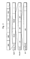
- Fig. 2 is a structural diagram showing the structure of the stream Str9 outputted by the conventional picture coding apparatus 900.
- the stream Str9 includes sequentially from the head a synchronous signal sync, a parameter set PS, plural random access units RAU9.
- Such stream Str9 complies with the JVT (H.264/MPEG-4 AVC) which is presently in process of standardization, jointly worked by the ITU-T and the ISO/IEC.
- the parameter set PS is common data equivalent to a header and includes a picture parameter set PPS is equivalent to a header of the picture, a sequence parameter set SPS equivalent to a header of a unit with a level superior to a random access unit RAU9.
- the sequence parameter set SPS includes a maximum possible number of reference pictures, a picture size, or the like
- the picture parameter set PPS includes a type of variable length coding (a switching between Huffman coding and arithmetic coding), an initial value in the quantization step, the number of reference pictures, or the like.
- the random access unit RAU9 includes sequentially from the head a synchronous signal sync and a plurality of coded pictures pic.
- the random access unit RAU9 as such is a single unit including the plural pictures in the stream Str9 and includes the special picture as mentioned above which can be decoded without depending ,on other pictures. Namely, the random access unit RAU9 is obtained by dividing the stream Str9 into a group of plural pictures including a special picture.
- the picture pic includes sequentially from the head a synchronous signal sync and a parameter set identifier PSID and plural pieces of pixel data pix.
- the parameter set identifier PSID indicates the sequence parameter set SPS and the picture parameter set PPS, which are included in the parameter set PS, to be referred to by the picture pic.
- the synchronous signal sync included in the head of the stream Str9, in the head of the random access unit RAU9 and in the head of the picture pic indicates respectively a section distinguishing the units such as the stream Str9, the random access unit RAU9 and the picture pic.
- a stream Str9 is generated in such a way that the parameter set PS is coded together and then placed at the head side of the stream Str9, whereas plural random access units RAU9, each of which does not include a picture parameter set PPS and a sequence parameter set SPS, follows the parameter set PS.
- the picture decoding apparatus When decoding such stream Str9, the picture decoding apparatus refers to the sequence parameter set SPS and the picture parameter set PPS included in the parameter set PS indicated by the parameter set identifier PSID in the picture pic so as to decode the picture pic.
- a conventional stream according to MPEG-2 has a structure different from the stream Str9.
- Fig. 3 is a structural diagram showing the structure of the conventional stream according to the MPEG-2.
- a stream Str8 according to the MPEG-2 includes sequentially from the head a synchronous signal sync, a header hed that is common data in the stream Str8 and a plurality of groups of pictures GOP.
- the group of picture GOP includes sequentially from the head a synchronous signal sync, a header hed that is common data for the group of pictures GOP and plural coded pictures pic.
- the group of picture GOP as such is a basic unit for coding and is used for editing a moving picture and performing random access.
- the picture pic included in the group of picture GOP is either I-picture, P-picture or B-picture.
- the picture pic includes sequentially from the head a synchronous signal sync, a header that is data common to the pictures pic and plural pieces of pixel data pix.
- a stream Str8 is generated in such a way that the header hed necessary for decoding the picture pic is included respectively in the heads of the stream Str8, each group of picture GOP and each picture pic.
- a problem is that the picture decoding apparatus cannot decode from a random access point that is a head of the random access unit RAU9 in the stream Str9 (i.e. random access) in an attempt to start performing random access, for example, in the case where the parameter set PS cannot be obtained since the stream Str9 is read out from the middle, as the parameter set PS is placed in one place at the head side of the stream Str9 according to the conventional picture coding method as described above, employed by the picture coding apparatus 900. Namely, the picture decoding apparatus cannot decode the picture pic properly because the corresponding picture parameter set PPS and sequence parameter set SPS are not found.
- the stream Str9 cannot be decoded from the middle when the picture decoding apparatus has read in the stream Str9 from the middle under the circumstance where the stream is inceimpulsly transmitted as in a case of broadcasting or delivery.
- the picture decoding apparatus firstly has to read the parameter set PS placed in the head of the stream Str9 on the recording medium and then start reading the stream Str9 from the random access point in the attempt to start performing random access for the stream Str9. That is to say that the picture decoding apparatus has to shift the position of reading the data from the head of the stream Str9 to the random access point, and thereby, a prompt random access cannot be operated since the shifting time becomes a waiting time for the random access.
- the waiting time is very long, and even if the disk is capable of high-speed reading, the waiting time may be prolonged to several seconds, which cannot be ignored.
- the picture decoding apparatus can perform random access for each group of picture GOP on the stream Str8 generated using the picture coding method according to the MPEG-2 by using the header hed in the group of picture GOP and the header hed in each picture pic.
- the picture coding method for generating such stream Str8 allows a generation of a stream Str8 to which random access can be performed, on one hand, however, decreases the coding efficiency on the other.
- the present invention is therefore conceived in view of the above circumstances, and an object of the present invention is to provide the picture coding method for coding a picture so that a prompt random access can be operated without reducing the coding efficiency.
- a picture coding apparatus as defined in claim 3 a picture decoding method as defined in claim 2
- a picture decoding apparatus as defined in claim 4 a picture decoding apparatus as defined in claim 4
- a recording medium as defined in claim 5 are proposed.
- a recording method is defined in claim 6.
- the present invention can be realized also as a picture coding apparatus or a program which uses the picture coding method as described above, or even as a bit stream generated using the picture coding method.
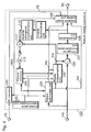
- Fig. 4 is a block diagram showing a structure of the picture coding apparatus according to the first embodiment of the present invention.
- the picture coding apparatus 100 codes a picture so that a prompt random access can be operated without reducing the coding efficiency. More precisely, the picture coding apparatus 100 codes an image signal Vin on a picture-by-picture basis and outputs a stream Str.
- the picture coding apparatus 100 includes a motion estimation unit 103, a motion compensation unit 105, a subtractor 106, an orthogonal transformation unit 107, a quantization unit 108, an inverse quantization unit 110, an inverse orthogonal transformation unit 111, an adder 112, a picture memory 104, a switch 113, a variable length coding unit 109, an access point determination unit 102 and a PS memory 101.
- Each of the components such as the motion estimation unit 103 executes the following processing per block or per macroblock that constitutes a picture.
- the subtractor 106 obtains an image signal Vin, and also, a predictive image Pre from the motion compensation unit 105, and calculates a differential between the image signal Vin and the predictive image Pre. The subtractor 106 then outputs the differential value to the orthogonal transformation unit 107.
- the orthogonal transformation unit 107 transforms the differential value into frequency coefficients and outputs them to the quantization unit 108.
- the quantization unit 108 quantizes the frequency coefficients obtained from the orthogonal transformation unit 107, and outputs the quantized values to the variable length coding unit 109.
- the inverse quantization unit 110 restores the quantized values obtained from the quantization unit 108 into the frequency coefficients by means of inverse quantization, and outputs them to the inverse orthogonal transformation unit 111.
- the inverse orthogonal transformation unit 111 performs inverse frequency transformation on the frequency coefficients outputted from the inverse quantization unit 110 in order to transform them into pixel differential values, and outputs them to the adder 112.
- the adder 112 adds the pixel differential values outputted from the inverse transformation unit 111 and the predictive image Pre outputted from the motion compensation unit 105, so as to generate a decoded image.
- the switch 113 connects the adder 112 and the picture memory 104, and allows the decoded image generated by the adder 112 to be stored in a picture memory.
- the decoded image stored in the picture memory is simply referred to as "picture".
- the motion estimation unit 103 obtains the image signal Vin on a macroblock-by-macroblock basis.
- the motion estimation unit 103 having obtained the image signal Vin, refers to the picture stored in the picture memory 104 as a reference picture, and specifies a picture area that resembles the obtained image signal Vin the most within the reference picture.
- the motion estimation unit 103 then estimates a motion vector MV indicating a location of the image area.
- the motion estimation unit 103 estimates such motion vector MV in units of blocks, each being obtained by further dividing a macroblock.
- the motion estimation unit 103 then, by using identification numbers (relative index Idx) for identifying the reference pictures, identifies the reference picture that has been referred to among plural reference picture candidates, based on the picture numbers assigned to each of the pictures stored in the picture memory 104.
- the motion compensation unit 105 extracts an image area that is the most applicable for the predictive image Pre from among the pictures (decoded images) stored in the picture memory 104, using the motion vector MV estimated in the above processing as well as the relative index Idx. The motion compensation unit 105 then generates a predictive image Pre using the extracted image area.
- the access point determination unit 102 instructs the motion estimation unit 103 and the motion compensation unit 105 to code (intra-picture code) a predetermined picture as a special picture per predetermined unit (i.e. random access unit).
- the access point determination unit 102 further outputs an access point identifier rapp indicating that a picture is the special picture to the variable length coding unit 109.
- the PS memory 101 obtains the parameter set PS and temporarily stores it.
- the PS memory 101 then outputs, based on the instruction from the access point determination unit 102, a picture parameter set and a sequence parameter set of the picture indicated in the instruction from the temporarily stored parameter sets PS to the variable length coding unit 109.
- variable length coding unit 109 codes the parameter set PS obtained from outside resources, the motion vector MV, the quantized values, the relative index Idx and the access point identifier rapp.
- the variable length coding unit 109 then generates a stream Str by arranging for each random access unit the sequence parameter set as well as the sequence parameter set included in the coded parameter set PS, and outputs the stream Str.
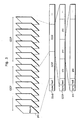
- Fig. 5 is a structural diagram showing a structure of the stream Str outputted by the picture coding apparatus 100 according to the present embodiment.
- the stream Str includes sequentially from the head a synchronous signal sync, a parameter set PS and plural random access units RAU.
- the parameter set PS includes plural sequence parameter sets SPS and plural picture parameter sets PPS.
- the random access unit RAU includes sequentially from the head a synchronous signal sync, a single sequence parameter set SPS, plural picture parameter sets PPS and plural coded pictures pic. Namely, such random access unit RAU includes all the sequence parameter sets SPS and the picture parameter sets PPS necessary for decoding all the pictures pic included there. Each of the picture parameter set PPS has a different value and any one of the picture parameter sets PPS is referred to by plural pictures pic and used for decoding the pictures.
- the picture pic includes sequentially from the head a synchronous signal sync, a parameter set identifier PSID and pixel data pix that is a codeword for pixels of the picture.
- the parameter set identifier PSID identifies the parameter sets SPS and PPS to be referred to by the picture from among the parameter sets SPS and PPS included in the random access unit RAU.
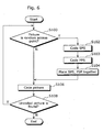
- Fig. 6 is a flowchart showing a picture coding method of the picture coding apparatus 100 according to the present embodiment.
- the picture coding apparatus 100 firstly judges whether or not a current picture to be coded is a random access point, namely, the first picture in the random access unit RAU (Step S100).
- the picture coding apparatus 100 codes the sequence parameter set SPS (Step S102) and further codes each picture parameter set PPS for all the pictures in the random access unit RAU (Step S103). The picture coding apparatus 100 then places the coded sequence parameter set SPS and plural picture parameter sets PPS together at the head side of the random access unit RAU (Step S104).
- the picture coding apparatus 100 codes the current picture (Step S106) either after placing the sequence parameter set SPS and the picture parameter sets PPS in Step S104 or when it is judged that the current picture is not a random access point (N in Step S100).
- the picture coding apparatus 100 places the coded current picture after the sequence parameter set SPS and the picture parameter sets PPS mentioned above. Namely, when the parameter sets SPS, PPS mentioned above are arranged in Step S104, the picture coding apparatus 100 places the parameter sets SPS, PPS before any of the pictures pic in the random access unit RAU.
- the picture coding apparatus 100 places the parameter set identifier PSID indicating the picture parameter set PPS necessary for decoding the picture pic before the codeword for the pixels of the picture (i.e. pixel data pix) within the coded current picture (i.e. picture pic).
- the picture coding apparatus 100 judges whether or not any uncoded pictures are found in the obtained image signal Vin (Step S108). When it is judged that an uncoded picture is found (Y in Step S108), the picture coding apparatus 100 operates repeatedly the operation starting from Step S100. When it is judged that no uncoded pictures are found, namely, when it is judged that all the pictures are coded (N in Step S108), the picture coding apparatus 100 terminates the processing of coding.
- the stream Str is generated using the picture coding method as described above.
- the stream Str is generated in such a way that the sequence parameter set SPS and the picture parameter sets PPS necessary for decoding (coding) all the pictures included in the random access unit RAU are placed in the random access unit RAU.
- the picture decoding apparatus therefore can start decoding properly, namely, can start performing random access, by referring to the sequence parameter set SPS and the picture parameter sets PPS included in the head of the random access unit RAU in the obtained stream Str, even when the stream Str is obtained in the middle.
- the picture coding apparatus also does not need to shift a position of reading the data, from the head of the stream Str to the random access point, and thereby, can start performing random access swiftly by omitting the waiting time for the random access, even when random access is performed by reading the stream Str from the recording medium.
- the stream Str in which the sequence parameter set SPS and the picture parameter sets PPS are included in each random access unit RAU, is generated, therefore, a stream whose bit amount is greater than that of the stream Str9 generated using the conventional picture coding method is generated.
- a header necessary for decoding is not placed per picture as in the conventional picture coding method according to the MPEG-2. Therefore, the coding efficiency can be further improved with the present picture coding method compared to the conventional picture coding method according to the MPEG-2.
- the picture coding apparatus 100 may generate structure identification information indicating a structure of the stream Str.
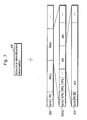
- Fig.7 is an illustration for explaining the information outputted from the picture coding apparatus 100.
- the picture coding apparatus 100 generates structure identification information sid as an attachment to the stream Str and outputs it.
- the structure identification information sid indicates that the sequence parameter set SPS and the picture parameter sets PPS are included in all the random access units RAU in the stream Str. That is to say that it is possible to perform random access from an arbitrary random access unit RAU in the stream Str.
- the picture decoding apparatus having obtained the stream Str and the structure identification information sid, can understand easily that the obtained stream Str can be decoded from an arbitrary random access unit RAU based on the structure identification information sid and perform random access by the fact the picture decoding apparatus attaches such structure identification information sid to the stream Str and outputs it.
- the picture coding apparatus 100 may include the structure identification information sid in the stream Str and output it.
- Fig. 8 is a structural diagram showing a structure of the stream Str that includes the structure identification information sid.
- the picture coding apparatus 100 generates a stream Str in such a way that the structure identification information sid is placed between a synchronous signal sync and a parameter set PS.
- the following describes the first variation of the picture coding apparatus according to the present embodiment described above.
- the picture coding apparatus outputs a stream in which a placement of the picture parameter set PPS is different from the stream Str outputted by the picture coding apparatus 100 according to the present embodiment described above.
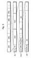
- Fig. 9 is a structural diagram showing a structure of the stream outputted by the picture coding apparatus according to the present variation.
- the picture coding apparatus outputs a stream Str1 that includes sequentially from the head a synchronous signal sync, a parameter set PS and plural random access units RAU1.
- the random access unit RAU1 includes sequentially from the head a synchronous signal sync, a sequence parameter set SPS, a picture parameter set PPS (PPS1) and two pictures pic1, pic2 , a picture parameter set PPS (PPS2) and a picture pic3.
- the picture parameter set PPS1 that is necessary for decoding the two pictures pic1 and pic2 is referred to by these pictures in common.
- the picture parameter set PPS2 that is unnecessary for decoding the pictures pic 1 and pic2 is not referred to by these pictures. That is to say, the picture parameter set PPS2 that is necessary for decoding the picture pic3 is referred to by the picture pic3.
- the picture parameter set PPS2 being referred to by the picture pic3 but not by the pictures pic1 and pic2, does not need to be placed before the pictures pic1 and pic2.
- the picture parameter PPS1 being referred to by the pictures pic1 and pic2, is already placed immediately before the picture pic1, therefore, does not need to be placed immediately before the picture pic2 again.
- the picture coding apparatus generates a stream Str1 so that the picture parameter set PPS referred to by a predetermined picture is placed immediately before the predetermined picture except for the case in which it is already placed.
- Fig. 10 is a flowchart showing the picture coding method employed by the picture coding apparatus according to the present variation.
- the picture coding apparatus firstly judges whether or not a current picture to be coded is a random access point, that is, the first picture in the random access unit RAU1 (Step S200).
- the picture coding apparatus codes a sequence parameter set SPS (Step S202) and places it at the head side of the random access unit RAU1 (Step S203).
- the picture coding apparatus further codes a picture parameter set PPS of the current picture (Step S204) and places it after the sequence parameter set SPS in the random access unit RAU1 (Step S205).
- the picture coding apparatus When judging that the current picture is not a random access point (N in Step S200), the picture coding apparatus further judges whether or not the picture parameter set PPS of the current picture is already coded and is placed after the random access point (Step S206).
- Step S206 When judging in Step S206 that the picture parameter set PPS of the current picture is not coded (N in Step S206), the picture coding apparatus codes the picture parameter set PPS of the current picture and places it (Steps S204 and S205).
- the picture coding apparatus codes the current picture (Step S208).
- the picture coding apparatus places the coded current picture (i.e. picture pic) immediately after the corresponding picture parameter set PPS when coding the current picture after the placement of the picture parameter set PPS performed in Step S205.
- the picture coding apparatus 100 places the picture parameter set PPS immediately before the coded current picture (i.e. picture pic) in the random access unit RAU in the placement of the picture parameter set PPS performed in Step S205.
- the picture coding apparatus When coding the current picture, the picture coding apparatus places a parameter set identifier PSID, which indicates a picture parameter set necessary for decoding the picture pic, before the codeword for the pixels of the picture (i.e. pixel data pix) in the coded current picture (i.e. picture pic).
- PSID parameter set identifier
- the picture coding apparatus judges whether or not any uncoded pictures are found in the obtained image signal Vin (Step S210).
- the picture coding apparatus executes repeatedly the operation starting from Step S200, and when it is judged that no uncoded pictures are found which means that all the pictures are coded (N in Step S210), the picture coding apparatus terminates the coding processing.
- the stream Str1 is generated using the picture coding method as described above.
- the structure of the picture coding apparatus according to the present variation can be more simplified than that of the picture coding apparatus 100.
- sequence parameter set SPS can be modified using a unit superior to the random access unit RAU, therefore, it is enough to place the random access unit RAU for one time.
- the following describes the second variation of the picture coding apparatus according to the present embodiment.
- the picture coding apparatus outputs a stream in which a placement of the sequence parameter set SPS is different from the placement in the stream outputted by the picture coding apparatus 100 according to the present embodiment described above.
- Fig. 11 is a structural diagram showing a structure of the stream outputted by the picture coding apparatus according to the present variation.
- the picture coding apparatus outputs a stream Str2 that includes sequentially from the head a synchronous signal sync, a parameter set PS and plural random access unit groups GRAU.
- the random access unit group GRAU includes sequentially from the head a sequence parameter set SPS and plural random access units RAU2. Namely, the random access unit group GRAU is constructed as a unit assembling plural random access units RAU2 for the convenience of storage and transmission.
- the sequence parameter set SPS is a parameter which can be modified using a unit superior to the random access unit RAU2. Therefore, the modification does not necessarily need to be made for each random access unit RAU2. Normally, only several sequence parameter sets SPS are required in the stream, and in many cases, only one sequence parameter set is enough.
- the picture coding apparatus does not place a sequence parameter set SPS for each random access unit RAU2, but for each random access unit group GRAU, that is, to place a single sequence parameter set SPS in the head of each random access unit group GRAU.
- the random access unit group GRAU includes a sequence parameter set SPS and a picture parameter set PPS which are necessary for decoding all the pictures included in it, therefore, the random access unit group GRAU is identifiable as the random access unit RAU or RAU1 according to the embodiment and the variation 1 described above.
- the RAU2 included in such random access unit group GRAU can be regarded as a subunit obtained by dividing the random access unit group GRAU.
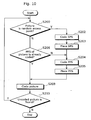
- Fig. 12 is a flowchart showing an operation of the picture coding apparatus according to the present variation.
- the picture coding apparatus firstly judges whether or not a current picture to be coded is the first picture included in the random access unit group GRAU (Step S300).
- the picture coding apparatus codes a sequence parameter set SPS (Step S302) and places it at the head side of the random access unit group GRAU (Step S303).
- the picture coding apparatus further codes the picture parameter set PPS of the current picture (Step S304) and places it at the head side of the random access unit RAU2 (Step S305).
- the picture coding apparatus When judging that the current picture is not the first picture included in the random access unit group GRAU (N in Step S300), the picture coding apparatus further judges whether or not the picture parameter set PPS of the current picture is already coded and is placed after the random access point (i.e., a head of the random access unit RAU2) (Step S306).
- Step S306 When it is judged in Step S306 that the picture parameter set PPS of the current picture is not coded (N in Step S306), the picture coding apparatus codes the picture parameter set PPS of the current picture and places it (Steps S304 and S305).
- Step S306 Either after the placement of the picture parameter set PPS performed in Step S305 or when judging in Step S306 that the picture parameter set PPS of the current picture is already coded (N in Step S 306), the picture coding apparatus codes the current picture (Step S308).
- the picture coding apparatus judges whether or not any uncoded pictures are found in the obtained image signal Vin (Step S310). When judging that an uncoded picture is found (Y in Step S310), the picture coding apparatus executes repeatedly the operation starting from Step S300. When judging that no uncoded pictures are found (N in Step S310), the picture coding apparatus terminates the coding processing.
- the stream Str2 in which only one sequence parameter set SPS is included in each random access unit group GRAU is generated using the picture coding method described above.
- the picture coding apparatus generates the stream Str2 in which a single sequence parameter set SPS is placed for plural random access units RAU2.
- the bit amount included in the stream Str2 therefore can be reduced more than the bit amount included in the stream Str generated by the picture coding apparatus 100 described above.
- a coded parameter set PS i.e. PPSs and SPSs
- PPSs and SPSs are placed at the head side of the stream, however, it may not be placed as such since it is placed, as necessary, in each random access unit RAU.
- the picture coding apparatus generates and outputs a stream different from the stream outputted by the picture coding apparatus 100 according to the present embodiment described above.
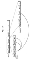
- Fig. 13 is a structural diagram showing a structure of the stream outputted by the picture coding apparatus according to the present variation.
- the picture coding apparatus outputs a stream Str3 that includes sequentially from the head a synchronous signal sync and plural random access units RAU (RAU0, RAU01, RAU02, ... ).
- the random access unit RAU01 includes sequentially from the head a synchronous signal sync, a parameter set PS (PS1), pictures pic1, pic2 and pic3.
- the random access unit RAU2 includes sequentially from the head a synchronous signal sync, random access point information RPS, a parameter set PS (PS2), pictures pic4, pic5 and pic6.
- the picture pic1 is an I-picture that is intra-picture coded whereas the picture pic2 is a P-picture that is coded with reference to the picture pic1.
- the picture pic3 is a B-picture that is coded with reference to the pictures pic1 and pic2.
- the picture pic4 is an I-picture that is intra-picture coded whereas the picture pic5 is a B-picture that is coded with reference to the pictures pic2 and pic4.
- the picture pic6 is a B-picture that is coded with reference to the picture pic4 and other pictures in the random access unit RAU02.
- the parameter set PS1 includes a sequence parameter set, picture parameter sets for the pictures pic2 and pic3 and a picture parameter set for the picture pic5 that is included in the random access unit RAU02.
- the picture pic2 is decoded with reference to the parameter set PS1 and the picture pic1 whereas the picture pic3 is decoded with reference to the parameter set PS1 and the pictures pic1 and pic2, when random access is performed on the stream Str3 starting from the random access unit RAU01.
- the picture pic5 included in the random access unit RAU02 is decoded with reference to the parameter set PS1 and the pictures pic2 and pic4
- the picture pic6 is decoded with reference to the parameter set PS2, the picture pic4 and other pictures included in the random access unit RAU02.
- a parameter set identifier PSID is included in the stream on a picture-by-picture basis.
- a parameter set identifier PSID may be included on a slice-by-slice basis.
- the random access unit shown in the embodiment and the variations 1-3 described above does not necessarily have to be a group of pictures including a picture of the special type defined by the JVT. It may be a group of pictures including simply an intra-picture coded picture (I-picture) in the head because of the fact that a parameter set PS is placed for each random access unit RAU as necessary.
- I-picture intra-picture coded picture
- a single sequence parameter set SPS and plural picture parameter sets PPS that are different from one another are coded for one time and placed for each random access unit RAU or each random access unit group GRAU.
- a plurality of the same coded sequence parameter sets SPS and a plurality of the same coded picture parameter sets PPS may be placed for each random access unit RAU or each random access unit group GRAU. Consequently, errors can be prevented, for example, at the time of decoding.
- processing illustrated in the above embodiment can be carried out easily in an independent computer system by recording a program for realizing the picture coding method described in the above embodiment onto a recording medium such as a flexible disk or the like.
- Figs 14A, 14B and 14C are illustrations of a recording medium, on which a program for carrying out the picture coding method described in the first embodiment in the computer system is recorded.
- Fig. 14B shows a full appearance of a flexible disk FD, its structure at cross section and a full appearance of the disk itself FD1 as a main body of a recording medium whereas Fig. 14A shows an example of a physical format of the flexible disk FD1.
- the disk FD1 is contained in a case F with a plurality of tracks Tr formed concentrically from the periphery to the inside on the surface of the disk FD1, and each track is divided into 16 sectors Se in the angular direction.
- the picture coding method as the program mentioned above is recorded in an area assigned for it on the disk FD1.
- Fig. 14C shows a structure for recording and reading out the program on the flexible disk FD.
- the computer system Cs When the program is recorded on the flexible disk FD, the computer system Cs writes in the picture coding method as the program mentioned above via a flexible disk drive FDD.
- the picture coding method is constructed in the computer system Cs using the program on the flexible disk FD, the program is read out from the flexible disk FD and then transferred to the computer system Cs by the flexible disk drive FDD.
- the flexible disk FD is used as an example of a recording medium, but the same processing can also be performed using an optical disk.
- the recording medium is not limited to these mentioned above, but any other medium capable of recording a program such as an IC card and a ROM cassette can be employed.
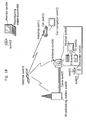
- Fig. 15 is a block diagram showing an overall configuration of a content supply system ex100 for realizing content delivery service.
- the area for providing communication service is divided into cells of desired size, and cell sites ex107-ex110, which are fixed wireless stations, are placed in respective cells.
- This content supply system ex100 is connected to apparatuses such as a computer ex111, a Personal Digital Assistant (PDA) ex112, a camera ex113, a cell phone ex114 and a cell phone with a camera ex115 via, for example, Internet ex101, an Internet service provider ex102, a telephone network ex104, as well as the cell sites ex107-ex110.
- PDA Personal Digital Assistant
- the content supply system ex100 is not limited to the configuration shown in Fig. 15 and may be connected to a combination of any of them. Also, each apparatus may be connected directly to the telephone network ex104, not through the cell sites ex107-ex110.
- the camera ex113 is an apparatus capable of shooting video such as a digital video camera.
- the cell phone ex114 may be a cell phone of any of the following system: a Personal Digital Communications (PDC) system, a Code Division Multiple Access (CDMA) system, a Wideband-Code Division Multiple Access (W-CDMA) system or a Global System for Mobile Communications (GSM) system, a Personal Handyphone System (PHS) or the like.
- PDC Personal Digital Communications
- CDMA Code Division Multiple Access
- W-CDMA Wideband-Code Division Multiple Access
- GSM Global System for Mobile Communications
- PHS Personal Handyphone System
- a streaming server ex103 is connected to the camera ex113 via the telephone network ex104 and also the cell site ex109, which realizes a live distribution or the like using the camera ex113 based on the coded data transmitted from the user. Either of the camera ex113, the server which transmits the data and the like may code the data.
- the moving picture data shot by a camera ex116 may be transmitted to the streaming server ex103 via the computer ex111. In this case, either the camera ex116 or the computer ex111 may code the moving picture data.
- An LSI ex.117 included in the computer ex111 and the camera ex116 performs the coding processing.
- Software for coding and decoding pictures may be integrated into any type of recording medium (such as a CD-ROM, a flexible disk and a hard disk) that is a recording medium which is readable by the computer ex111 or the like.
- a cell phone with a camera ex115 may transmit the moving picture data. This moving picture data is the data coded by the LSI included in the cell phone ex115.
- the content supply system ex100 codes contents (such as a music live video) shot by a user using the camera ex113, the camera ex116 or the like in the same way as shown in the above-mentioned embodiment and transmits them to the streaming server ex103, while the streaming server ex103 makes stream deliver of the content data to the clients at their requests.
- the clients include the computer ex111, the PDA ex112, the camera ex113, the cell phone ex114 and so on capable of decoding the above-mentioned coded data. In the content supply system ex100, the clients can thus receive and reproduce the coded data, and can further receive, decode and reproduce the data in real time so as to realize personal broadcasting.
- the picture coding apparatus or the picture decoding apparatus shown in the above-mentioned embodiment can be used.
- a cell phone will be explained as an example of such apparatus.
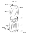
- Fig. 16 is a diagram showing the cell phone ex115 using the picture coding method explained in the above-mentioned embodiment.
- the cell phone ex115 has an antenna ex201 for communicating with the cell site ex110 via radio waves, a camera unit ex203 such as a CCD camera capable of shooting moving and still pictures, a display unit ex202 such as a liquid crystal display for displaying the data such as decoded pictures and the like shot by the camera unit ex203 or received by the antenna ex201, a body unit including a set of operation keys ex204, a voice output unit ex208 such as a speaker for outputting voice, a voice input unit ex205 such as a microphone for inputting voice, a recording medium ex207 for recording coded or decoded data such as data of moving or still pictures shot by the camera, data of received e-mails and that of moving or still pictures, and a slot unit ex206 for attaching the recording medium ex207 to the cell phone ex115.
- a camera unit ex203 such as a CCD camera capable of shooting moving and still pictures
- the recording medium ex207 stores in itself a flash memory element, a kind of Electrically Erasable and Programmable Read Only Memory (EEPROM) that is a nonvolatile memory electrically erasable from and rewritable to a plastic case such as an SD card.
- EEPROM Electrically Erasable and Programmable Read Only Memory
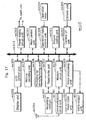
- a main control unit ex311 designed in order to control overall each unit of the main body which contains the display unit ex202 as well as the operation keys ex204, is connected mutually to a power supply circuit unit ex310, an operation input control unit ex304, a picture coding unit ex312, a camera interface unit ex303, a Liquid Crystal Display (LCD) control unit ex302, a picture decoding unit ex309, a multiplexing/demultiplexing unit ex308, a read/write unit ex307, a modem circuit unit ex306 and a voice processing unit ex305 via a synchronous bus ex313.
- LCD Liquid Crystal Display
- the power supply circuit unit ex310 supplies the respective units with power from a battery pack so as to activate the digital cell phone with a camera ex115 as a ready state.
- the voice processing unit ex305 converts the voice signals received by the voice input unit ex205 in conversation mode into digital voice data under the control of the main control unit ex311 including a CPU, ROM and RAM, the modem circuit unit ex306 performs spread spectrum processing for the digital voice data, and the communication circuit unit ex301 performs digital-to-analog conversion and frequency conversion for the data, so as to transmit it via the antenna ex201.
- the main control unit ex311 including a CPU, ROM and RAM
- the modem circuit unit ex306 performs spread spectrum processing for the digital voice data
- the communication circuit unit ex301 performs digital-to-analog conversion and frequency conversion for the data, so as to transmit it via the antenna ex201.
- the communication circuit unit ex301 amplifies the data received by the antenna ex201 in conversation mode and performs frequency conversion and the analog-to-digital conversion to the data, the modem circuit unit ex306 performs inverse spread spectrum processing of the data, and the voice processing unit ex305 converts it into analog voice data so as to output it via the voice output unit ex208.
- the text data of the e-mail inputted by operating the operation keys ex204 of the main body is sent out to the main control unit ex311 via the operation input control unit ex304.
- the modem circuit unit ex306 performs spread spectrum processing of the text data
- the communication circuit unit ex301 performs the digital-to-analog conversion and the frequency conversion for the text data
- the data is transmitted to the cell site ex110 via the antenna ex201.
- the picture data shot by the camera unit ex203 is supplied to the picture coding unit ex312 via the camera interface unit ex303.
- the picture data shot by the camera unit ex203 is also possible to display the picture data shot by the camera unit ex203 directly on the display unit ex202 via the camera interface unit ex303 and the LCD control unit ex302.
- the picture coding unit ex312 which includes the picture coding apparatus as described for the present invention, compressed and codes the picture data supplied from the camera unit ex203 using the coding method employed by the picture coding apparatus as shown in the embodiment mentioned above so as to transform it into coded image data, and sends it out to the multiplexing/demultiplexing unit ex308.
- the cell phone ex115 sends out the voice received by the voice input unit ex205 during the shooting with the camera unit ex203 to the multiplexing/demultiplexing unit ex308 as digital voice data via the voice processing unit ex305.
- the multiplexing/demultiplexing unit ex308 multiplexes the coded image data supplied from the picture coding unit ex312 and the voice data supplied from the voice processing unit ex305, using a predetermined method, then the modem circuit unit ex306 performs spread spectrum processing of the multiplexed data obtained as a result of the multiplexing, and lastly the communication circuit unit ex301 performs digital-to-analog conversion and frequency transform of the data for the transmission via the antenna ex201.
- the modem circuit unit ex306 performs inverse spread spectrum processing for the data received from the cell site ex110 via the antenna ex201, and sends out the multiplexed data obtained as a result of the inverse spread spectrum processing.
- the multiplexing/demultiplexing unit ex308 demultiplexes the multiplexed data into a bit stream of image data and that of voice data, and supplies the coded image data to the picture decoding unit ex309 and the voice data to the voice processing unit ex305, respectively via the synchronous bus ex313.
- the picture decoding unit ex309 decodes the bit stream of the image data using the decoding method corresponding to the coding method as shown in the above-mentioned embodiments to generate reproduced moving picture data, and supplies this data to the display unit ex202 via the LCD control unit ex302, and thus the image data included in the moving picture file linked to a Web page, for instance, is displayed.
- the voice processing unit ex305 converts the voice data into analog voice data, and supplies this data to the voice output unit ex208, and thus the voice data included in the moving picture file linked to a Web page, for instance, is reproduced.
- the present invention is not limited to the above-mentioned system since ground-based or satellite .digital broadcasting has been in the news lately and at least either the picture coding apparatus or the picture decoding apparatus described in the above-mentioned embodiment can be incorporated into a digital broadcasting system as shown in Fig. 18 . More specifically, a bit stream of video information is transmitted from a broadcast station ex409 to or communicated with a broadcast satellite ex410 via radio waves. Upon receipt of it, the broadcast satellite ex410 transmits radio waves for broadcasting.
- a home-use antenna ex406 with a satellite broadcast reception function receives the radio waves, and a television (receiver) ex401 or a set top box (STB) ex407 decodes a coded bit stream for reproduction.
- the picture decoding apparatus as shown in the above-mentioned embodiment can be implemented in the reproducing apparatus ex403 for reading out and decoding the bit stream recorded on a recording medium ex402 such as a CD and a DVD. In this case, the reproduced moving picture signals are displayed on a monitor ex404.
- the picture decoding apparatus in the set top box ex407 connected to a cable ex405 for a cable television or the antenna ex406 for satellite and/or ground-based broadcasting so as to reproduce them on a monitor ex408 of the television ex401.
- the picture decoding apparatus may be incorporated into the television, not in the set top box.
- a car ex412 having an antenna ex411 can receive signals from the satellite ex410 or the cell site ex107 for replaying moving picture on a display device such as a car navigation system ex413 set in the car ex412.
- the picture coding apparatus as shown in the above-mentioned embodiment can code picture signals and record them on the recording medium.
- a recorder ex420 such as a DVD recorder for recording picture signals on a DVD disk ex421, a disk recorder for recording them on a hard disk can be cited. They can be recorded on an SD card ex422.
- the recorder ex420 includes the picture decoding apparatus as shown in the above-mentioned embodiment, the picture signals recorded on the DVD disk ex421 or the SD card ex422 can be reproduced for display on the monitor ex408.
- the structure of the car navigation system ex413 the structure without the camera unit ex203, the camera interface unit ex303 and the picture coding unit ex312, out of the components shown in Fig. 17 , is conceivable.
- a terminal such as the cell phone ex114: a sending/receiving terminal implemented with both an encoder and a decoder, a sending terminal implemented with an encoder only, and a receiving terminal implemented with a decoder only.
- the picture coding method according to the present invention allows coding of pictures so that random access can be performed without reducing the coding efficiency.
- the present picture coding method can be employed by a picture coding apparatus, such as a video camera, a cell phone with a recording function, or the like, which codes pictures using the method.
Abstract
Description
- The present invention relates to a picture coding method for coding a picture.
- "H.26L OVER IP AND H.324 FRAMEWORK" (ITU TELECOMMUNICATIONS STANDARDIZATION SECTOR VCEG-N52, 18 September 2001, pages 1-13), by S. Wenger et al. discusses one possible concept for the transport of H.26L over IP and H.324 networks. Any information that is concerned with more than a single slice is conveyed out of band. In particular, all information previously conveyed in the picture header and higher header layers, such as the picture size, entropy coding method, optional modes and similar are never sent in the RTP stream.
- The decoder maintains parameters sets in numbered storage locations. The simplest systems will need at least two storage locations, one for Intra slices and one for Inter slices. More complex systems maintain a multitude of parameter storage spaces for different picture resolutions, coding modes, and similar. Each slice contains in its header partition the information which storage space to use. Synchronization between updates of the parameter storage (when desired) and the media streams is handled externally.
- For the parameter information a syntax is proposed that can one-to-one be converted into SDP, the description language used by SIP systems (such as 3GPP phones).
-
US 6,031,960 describes methods and apparatus for insuring that a trick play data stream, e.g., a stream of data used for fast forward or reverse playback operation, complies with preselected data standards and in particular the MPEG-2 standard are disclosed in,US 6,031,960 . Various methods are described for generating PCR, PTS and DTS values for a trick play data stream, which is generated from a normal play data steam, and is intended for recording in trick play segments of a tape. The described methods include generating new PCR, PTS and DTS values as a function of the trick play speed at which the data is intended to be read back. Methods and apparatus for correcting PCR, PTS and DTS values read from a tape during trick playback operation are also disclosed. The disclosed methods are directed to generating new PCRs, PTSs and DTSs to provide am MPEG-2 compliant bitstream. The described methods and apparatus are applicable to a plurality of storage and playback devices capable of implementing trick play including compact disks. - To solve the problems that it is difficult to secure a real time property of the time of recording at the time of reproduction when reproducing recorded data and the using efficiency of a capacity lowers in the case that a recording medium is provided with the minimum recording unit of a fixed size, it is proposed in
JP 2001285800 - Recently, with an arrival of the age of multimedia which handles Integrally audio, video and pixel values of others, existing information media, i.e., newspapers, journals, TVs, radios and teiephones and other means through which information is conveyed to people, has come under the scope of multimedia.
- Generally speaking, multimedia refers to a representation in which not only characters but also graphics, audio and especially pictures and the like are related to each other. However, in order to include the aforementioned existing information media in the scope of multimedia, it appears as a prerequisite to represent such information in digital form.
- However, when calculating the amount of information contained in each of the aforementioned information media as the amount of digital information, the information amount per character requires 1-2 bytes whereas the audio requires more than 64 Kbits (telephone quality) per second and when it comes to the moving picture, it requires more than 100Mbits (present television reception quality) per second. Therefore, it is not realistic to handle the vast information directly in digital form via the information media mentioned above. For example, a videophone has already been put into practical use via Integrated Services Digital Network (ISDN) with a transmission rate of 64 Kbit/s - 1.5 Mbit/s, however, it is impossible to transmit video captured on the TV screen or shot by a TV camera.
- This therefore requires information compression techniques, and for instance, in the case of the videophone, video compression techniques compliant with H.261 and H.263 standards internationally standardized by International Telecommunication Union-Telecommunication Standardization Sector (ITU-T) are employed. According to the information compression techniques compliant with the MPEG-1 standard, picture information as well as audio information can be stored in an ordinary music CD (Compact Disc).
- The Moving Picture Experts Group (MPEG) is an international standard for a compression of moving picture signals and MPEG-1 is a standard that compresses video signals down to 1.5 Mbit/s, namely, to compress the information included in TV signals approximately down to a hundredth. The quality targeted in the MPEG-1 standard was the medium quality so as to realize a transmission rate primarily of about 1.5 Mbit/s, therefore, PEG-2, standardized with the view to meet the requirements of high-quality picture realizes a TV broadcast quality for transmitting moving picture signals with a transmission rate of 2-15 Mbit/s. In the present circumstances, a working group (ISO/IEC JTC1/SC29/WG11) previously in the charge of the standardization of the MPEG-1 and the MPEG-2 has standardized MPEG-4 which achieves a compression rate superior to the one achieved by the MPEG-1 and the MPEG-2, allows coding/decoding operations on a per-object basis and realizes a new function required by the era of multi media. At first, in the process of the standardization of the MPEG-4, the standardization of a coding method for a low bit rate was aimed, however, the aim is presently extended to a more versatile coding including a coding of moving pictures at a high bit rate and a coding of interlace pictures. Moreover, a standardization of MPEG-4 AVC and ITU H.264 is in process as a next generation coding method with a higher compression rate, jointly worked by the ITU-T and the ISO/IEC. The next generation coding method is published under the name of Committee Draft (CD) as of August 2002.
- In coding of a moving picture, compression of information volume is usually performed by eliminating redundancy both in spatial and temporal directions. Therefore, inter-picture prediction coding, which aims at reducing the temporal redundancy, estimates a motion and generates a predictive picture on a block-by-block basis with reference to forward and backward pictures, and then codes a differential value between the obtained predictive picture and a current picture to be coded. Here, "picture" is a term to represent a single screen and it represents a frame when used for a progressive picture whereas it represents a frame or a field when used for an interlaced picture. The interlaced picture here is a picture in which a single frame consists of two fields having different time. For coding and decoding an interlaced picture, three ways are possible: handling a single frame either as a frame, as two fields or as a frame structure or a field structure depending on a block in the frame.
- A picture to which intra-picture prediction coding is performed without reference pictures is called I-picture. A picture to which inter-picture prediction cording is performed with reference to a single picture is called P-picture. A picture to which inter-picture prediction coding is performed by referring simultaneously to two pictures is called B-picture. Two pictures whose display time is either forward or backward to that of a current picture to be coded can be selected arbitrarily as reference for coding B-picture. The reference pictures can be specified for each block which is a basic unit for coding and decoding, but they can be classified as the first reference picture for a reference picture that is described first in a coded bit stream and a picture that is described later as the second reference picture. However, the reference pictures need to be already coded or decoded as a condition to code or decode these I, P and B pictures.
- A motion compensation inter-picture prediction coding is employed for coding P-pictures or B-pictures. The motion compensation inter-picture prediction coding is a coding method applying motion compensation to inter-picture prediction coding. The motion compensation is not a method to simply predict motions using pixels in the reference pictures but to estimate a motion (to be referred to as "motion vector" hereinafter) at each part within a picture and improve prediction accuracy by performing prediction that takes the motion vector into consideration as well as to reduce the data amount. For example, the amount of data is reduced by estimating the motion vector for a current picture to be coded and coding prediction error between a predictive value, which is obtained after being shifted for the amount equivalent to the motion vector, and the current picture. In the case of using this method, information on motion vectors is required at the time of decoding, therefore, the motion vectors are coded and then recorded or transmitted.
- A motion vector is estimated on a block-by-block basis. More precisely, a motion vector is estimated by fixing a block in the current picture, then, shifting a block in the reference picture within a range of search, and finding out a location of the reference block that resembles a basic block.
-
Fig. 1 is a block diagram showing the structure of the conventional picture coding apparatus. - A
picture coding apparatus 900 outputs a coded image signal (to be referred to as "bit stream") Str9 which is a bit stream obtained by coding an image signal Vin on a picture-by-picture basis, and includes amotion estimation unit 903, amotion compensation unit 905, asubtractor 906, anorthogonal transformation unit 907, aquantization unit 908, aninverse quantization unit 910, an inverseorthogonal transformation unit 911, anadder 912, apicture memory 904, aswitch 913, a variablelength coding unit 909 and an accesspoint determination unit 902. Each component such as themotion estimation unit 903 executes the following processing per block or per macroblock that constitutes a picture. - The
subtractor 906 calculates a differential value between the image signal Vin and a predictive image Pre and outputs the differential value to theorthogonal transformation unit 907. Theorthogonal transformation unit 907 transforms the differential value into frequency coefficients and outputs them to thequantization unit 908. Thequantization unit 908 quantizes the frequency coefficients and outputs the quantized values to the variablelength coding unit 909. Theinverse quantization unit 910 restores the frequency coefficients by inversely quantizes the quantized values and outputs the frequency coefficients to the inverseorthogonal transformation unit 911. - The inverse
orthogonal transformation unit 911 performs inverse frequency transformation on the frequency coefficients outputted from theinverse quantization unit 910 into pixel differential values and outputs them to theadder 912. Theadder 912 adds the pixel differential values outputted from the inverseorthogonal transformation unit 911 and the predictive image Pre outputted from themotion compensation unit 905, and generates a decoded image. Theswitch 913 connects theadder 912 and thepicture memory 904 so that thepicture memory 904 stores the decoded image generated by theadder 912. The decoded image stored in the picture memory is simply referred to as "picture" hereinafter. - The
motion estimation unit 903 refers to the picture stored in thepicture memory 904 as a reference picture and specifies an image area that resembles the image signal Vin the most among the reference pictures. Then, themotion estimation unit 903 estimates a motion vector MV indicating a position of the image area. - The
motion estimation unit 903 also identifies a reference picture that resembles the image signal Vin out of the plural reference pictures using identification numbers (relative index Idx) for identifying the reference picture. - The
motion compensation unit 905 extracts an image area that is the most applicable to the predictive image Pre from among the pictures stored in thepicture memory 904 using the motion vector MV and the relative index Idx. Themotion compensation unit 905 then generates a predictive image Pre from the extracted image area. - The access
point determination unit 902 instructs themotion estimation unit 903 and themotion compensation unit 905 to code (intra-picture code) per predetermined unit (random access unit) a predetermined picture as a special picture. The special picture here means a picture from which the decoding can be started in thestream Str 9. Furthermore, the accesspoint determination unit 902 outputs an access point identifier rapp indicating that a picture is the special picture to the variablelength coding unit 909. - The variable
length coding unit 909 codes a parameter set PS obtained from outside resources, the motion vector MV, the quantized values, the relative index Inx and the access point identifier rapp, generates a stream Str9 in which the coded parameter set is placed only at the head side, and outputs the stream Str9. -
Fig. 2 is a structural diagram showing the structure of the stream Str9 outputted by the conventionalpicture coding apparatus 900. - The stream Str9 includes sequentially from the head a synchronous signal sync, a parameter set PS, plural random access units RAU9. Such stream Str9 complies with the JVT (H.264/MPEG-4 AVC) which is presently in process of standardization, jointly worked by the ITU-T and the ISO/IEC.
- The parameter set PS is common data equivalent to a header and includes a picture parameter set PPS is equivalent to a header of the picture, a sequence parameter set SPS equivalent to a header of a unit with a level superior to a random access unit RAU9. The sequence parameter set SPS includes a maximum possible number of reference pictures, a picture size, or the like, whereas the picture parameter set PPS includes a type of variable length coding (a switching between Huffman coding and arithmetic coding), an initial value in the quantization step, the number of reference pictures, or the like.
- The random access unit RAU9 includes sequentially from the head a synchronous signal sync and a plurality of coded pictures pic. The random access unit RAU9 as such is a single unit including the plural pictures in the stream Str9 and includes the special picture as mentioned above which can be decoded without depending ,on other pictures. Namely, the random access unit RAU9 is obtained by dividing the stream Str9 into a group of plural pictures including a special picture.
- The picture pic includes sequentially from the head a synchronous signal sync and a parameter set identifier PSID and plural pieces of pixel data pix.
- The parameter set identifier PSID indicates the sequence parameter set SPS and the picture parameter set PPS, which are included in the parameter set PS, to be referred to by the picture pic.
- The synchronous signal sync included in the head of the stream Str9, in the head of the random access unit RAU9 and in the head of the picture pic indicates respectively a section distinguishing the units such as the stream Str9, the random access unit RAU9 and the picture pic.
- Namely, in the picture coding method in which the conventional
picture coding apparatus 900 generates a stream Str9 by coding the image signal Vin, a stream Str9 is generated in such a way that the parameter set PS is coded together and then placed at the head side of the stream Str9, whereas plural random access units RAU9, each of which does not include a picture parameter set PPS and a sequence parameter set SPS, follows the parameter set PS. - When decoding such stream Str9, the picture decoding apparatus refers to the sequence parameter set SPS and the picture parameter set PPS included in the parameter set PS indicated by the parameter set identifier PSID in the picture pic so as to decode the picture pic.
- A conventional stream according to MPEG-2 has a structure different from the stream Str9.
-
Fig. 3 is a structural diagram showing the structure of the conventional stream according to the MPEG-2. - A stream Str8 according to the MPEG-2 includes sequentially from the head a synchronous signal sync, a header hed that is common data in the stream Str8 and a plurality of groups of pictures GOP.
- The group of picture GOP includes sequentially from the head a synchronous signal sync, a header hed that is common data for the group of pictures GOP and plural coded pictures pic.
- The group of picture GOP as such is a basic unit for coding and is used for editing a moving picture and performing random access. The picture pic included in the group of picture GOP is either I-picture, P-picture or B-picture.
- The picture pic includes sequentially from the head a synchronous signal sync, a header that is data common to the pictures pic and plural pieces of pixel data pix.
- Namely, in the picture coding method according to the MPEG-2 for generating a stream Str8 by coding the conventional image signal Vin, a stream Str8 is generated in such a way that the header hed necessary for decoding the picture pic is included respectively in the heads of the stream Str8, each group of picture GOP and each picture pic.
- However, a problem is that the picture decoding apparatus cannot decode from a random access point that is a head of the random access unit RAU9 in the stream Str9 (i.e. random access) in an attempt to start performing random access, for example, in the case where the parameter set PS cannot be obtained since the stream Str9 is read out from the middle, as the parameter set PS is placed in one place at the head side of the stream Str9 according to the conventional picture coding method as described above, employed by the
picture coding apparatus 900. Namely, the picture decoding apparatus cannot decode the picture pic properly because the corresponding picture parameter set PPS and sequence parameter set SPS are not found. - More precisely, the stream Str9 cannot be decoded from the middle when the picture decoding apparatus has read in the stream Str9 from the middle under the circumstance where the stream is incessantly transmitted as in a case of broadcasting or delivery.
- In the case where the stream Str9 is recorded on a recording medium such as a tape or a disk, the picture decoding apparatus firstly has to read the parameter set PS placed in the head of the stream Str9 on the recording medium and then start reading the stream Str9 from the random access point in the attempt to start performing random access for the stream Str9. That is to say that the picture decoding apparatus has to shift the position of reading the data from the head of the stream Str9 to the random access point, and thereby, a prompt random access cannot be operated since the shifting time becomes a waiting time for the random access.
- In the case where the recording medium is a tape, it is apparent that the waiting time is very long, and even if the disk is capable of high-speed reading, the waiting time may be prolonged to several seconds, which cannot be ignored.
- The picture decoding apparatus can perform random access for each group of picture GOP on the stream Str8 generated using the picture coding method according to the MPEG-2 by using the header hed in the group of picture GOP and the header hed in each picture pic.
- With the use of the picture coding method for generating such stream Str8, however, the compression rate of the stream Str8 is low since each of the pictures pic included in the group of picture GOP has a header hed and many of such headers hed have the same value as other headers hed. That is to say, the picture coding method for generating a stream Str8 allows a generation of a stream Str8 to which random access can be performed, on one hand, however, decreases the coding efficiency on the other.
- The present invention is therefore conceived in view of the above circumstances, and an object of the present invention is to provide the picture coding method for coding a picture so that a prompt random access can be operated without reducing the coding efficiency.
- In order to achieve the above object, the picture coding method according to the present invention as defined in
claim 1 is proposed. - Further, a picture coding apparatus as defined in claim 3, a picture decoding method as defined in
claim 2, a picture decoding apparatus as defined inclaim 4 and a recording medium as defined inclaim 5 are proposed. In addition, a recording method is defined inclaim 6. - The present invention can be realized also as a picture coding apparatus or a program which uses the picture coding method as described above, or even as a bit stream generated using the picture coding method.
-
-
Fig. 1 is a block diagram showing a structure of the conventional picture coding apparatus. -
Fig. 2 is a structural diagram showing a structure of the stream outputted by the conventional picture coding apparatus. -
Fig. 3 is a structural diagram showing a structure of the stream according to the MPEG-2. -
Fig. 4 is a block diagram showing a structure of the picture coding apparatus according to the first embodiment of the present invention. -
Fig. 5 is a structural diagram showing the structure of the coded image signal outputted by the picture coding apparatus according to the first embodiment of the present invention. -
Fig. 6 is a flowchart showing the picture coding method according to the first embodiment of the present invention. -
Fig. 7 is an illustration for describing the information outputted from the picture coding apparatus according to the first embodiment of the present invention. -
Fig. 8 is a structural diagram showing a structure of the stream Str that includes structure identification information according to the first embodiment of the present invention. -
Fig. 9 is a structural diagram showing a structure of the stream outputted by the picture coding apparatus according to a first variation described in the first embodiment of the present invention. -
Fig. 10 is a flowchart showing an operation of the picture coding apparatus according to the first variation described in the first embodiment of the present invention. -
Fig. 11 is a structural diagram showing a structure of the stream outputted by the picture coding apparatus according to a second variation described in the first embodiment of the present invention. -
Fig. 12 is a flowchart showing an operation of the picture coding apparatus according to the second variation described in the first embodiment. -
Fig. 13 is a structural diagram showing a structure of the stream outputted by the picture coding apparatus according to a third variation of the first embodiment. -
Fig. 14A, 14B and 14C are illustrations of a recording medium on which a program for realizing the picture coding method according to the first embodiment of the present invention in a computer system is recorded, according to the second embodiment of the present invention. -
Fig. 15 is a block diagram showing a whole structure of a content supply system for realizing a content distribution service according to the third embodiment of the present invention; -
Fig. 16 is a diagram showing a cell phone according to the third embodiment of the present invention using the picture coding method described in the first embodiment. -
Fig. 17 is a block diagram showing the internal structure of the cell phone according to the third embodiment of the present invention. -
Fig. 18 is a structural diagram showing the structure of the digital broadcasting system according to the third embodiment of the present invention. - The following describes the embodiments of the present invention with reference to the figures.
-
Fig. 4 is a block diagram showing a structure of the picture coding apparatus according to the first embodiment of the present invention. - The
picture coding apparatus 100 according to the present embodiment codes a picture so that a prompt random access can be operated without reducing the coding efficiency. More precisely, thepicture coding apparatus 100 codes an image signal Vin on a picture-by-picture basis and outputs a stream Str. - The
picture coding apparatus 100 includes amotion estimation unit 103, amotion compensation unit 105, asubtractor 106, anorthogonal transformation unit 107, aquantization unit 108, aninverse quantization unit 110, an inverseorthogonal transformation unit 111, anadder 112, apicture memory 104, aswitch 113, a variablelength coding unit 109, an accesspoint determination unit 102 and aPS memory 101. Each of the components such as themotion estimation unit 103 executes the following processing per block or per macroblock that constitutes a picture. - The
subtractor 106 obtains an image signal Vin, and also, a predictive image Pre from themotion compensation unit 105, and calculates a differential between the image signal Vin and the predictive image Pre. Thesubtractor 106 then outputs the differential value to theorthogonal transformation unit 107. - The
orthogonal transformation unit 107 transforms the differential value into frequency coefficients and outputs them to thequantization unit 108. - The
quantization unit 108 quantizes the frequency coefficients obtained from theorthogonal transformation unit 107, and outputs the quantized values to the variablelength coding unit 109. - The
inverse quantization unit 110 restores the quantized values obtained from thequantization unit 108 into the frequency coefficients by means of inverse quantization, and outputs them to the inverseorthogonal transformation unit 111. - The inverse
orthogonal transformation unit 111 performs inverse frequency transformation on the frequency coefficients outputted from theinverse quantization unit 110 in order to transform them into pixel differential values, and outputs them to theadder 112. - The
adder 112 adds the pixel differential values outputted from theinverse transformation unit 111 and the predictive image Pre outputted from themotion compensation unit 105, so as to generate a decoded image. - In the case where an instruction to store the decoded image generated by the
adder 112 is received, theswitch 113 connects theadder 112 and thepicture memory 104, and allows the decoded image generated by theadder 112 to be stored in a picture memory. The decoded image stored in the picture memory is simply referred to as "picture". - The
motion estimation unit 103 obtains the image signal Vin on a macroblock-by-macroblock basis. Themotion estimation unit 103, having obtained the image signal Vin, refers to the picture stored in thepicture memory 104 as a reference picture, and specifies a picture area that resembles the obtained image signal Vin the most within the reference picture. Themotion estimation unit 103 then estimates a motion vector MV indicating a location of the image area. - The
motion estimation unit 103 estimates such motion vector MV in units of blocks, each being obtained by further dividing a macroblock. Themotion estimation unit 103, then, by using identification numbers (relative index Idx) for identifying the reference pictures, identifies the reference picture that has been referred to among plural reference picture candidates, based on the picture numbers assigned to each of the pictures stored in thepicture memory 104. - The
motion compensation unit 105 extracts an image area that is the most applicable for the predictive image Pre from among the pictures (decoded images) stored in thepicture memory 104, using the motion vector MV estimated in the above processing as well as the relative index Idx. Themotion compensation unit 105 then generates a predictive image Pre using the extracted image area. - The access
point determination unit 102 instructs themotion estimation unit 103 and themotion compensation unit 105 to code (intra-picture code) a predetermined picture as a special picture per predetermined unit (i.e. random access unit). The accesspoint determination unit 102 further outputs an access point identifier rapp indicating that a picture is the special picture to the variablelength coding unit 109. - The
PS memory 101 obtains the parameter set PS and temporarily stores it. ThePS memory 101 then outputs, based on the instruction from the accesspoint determination unit 102, a picture parameter set and a sequence parameter set of the picture indicated in the instruction from the temporarily stored parameter sets PS to the variablelength coding unit 109. - The variable
length coding unit 109 codes the parameter set PS obtained from outside resources, the motion vector MV, the quantized values, the relative index Idx and the access point identifier rapp. The variablelength coding unit 109 then generates a stream Str by arranging for each random access unit the sequence parameter set as well as the sequence parameter set included in the coded parameter set PS, and outputs the stream Str. -
Fig. 5 is a structural diagram showing a structure of the stream Str outputted by thepicture coding apparatus 100 according to the present embodiment. - The stream Str includes sequentially from the head a synchronous signal sync, a parameter set PS and plural random access units RAU.
- The parameter set PS includes plural sequence parameter sets SPS and plural picture parameter sets PPS.
- The random access unit RAU includes sequentially from the head a synchronous signal sync, a single sequence parameter set SPS, plural picture parameter sets PPS and plural coded pictures pic. Namely, such random access unit RAU includes all the sequence parameter sets SPS and the picture parameter sets PPS necessary for decoding all the pictures pic included there. Each of the picture parameter set PPS has a different value and any one of the picture parameter sets PPS is referred to by plural pictures pic and used for decoding the pictures.
- The picture pic includes sequentially from the head a synchronous signal sync, a parameter set identifier PSID and pixel data pix that is a codeword for pixels of the picture.
- The parameter set identifier PSID identifies the parameter sets SPS and PPS to be referred to by the picture from among the parameter sets SPS and PPS included in the random access unit RAU.
-
Fig. 6 is a flowchart showing a picture coding method of thepicture coding apparatus 100 according to the present embodiment. - The
picture coding apparatus 100 firstly judges whether or not a current picture to be coded is a random access point, namely, the first picture in the random access unit RAU (Step S100). - When judging that the current picture is a random access point (Y in Step S100), the
picture coding apparatus 100 codes the sequence parameter set SPS (Step S102) and further codes each picture parameter set PPS for all the pictures in the random access unit RAU (Step S103). Thepicture coding apparatus 100 then places the coded sequence parameter set SPS and plural picture parameter sets PPS together at the head side of the random access unit RAU (Step S104). - The
picture coding apparatus 100 codes the current picture (Step S106) either after placing the sequence parameter set SPS and the picture parameter sets PPS in Step S104 or when it is judged that the current picture is not a random access point (N in Step S100). Thepicture coding apparatus 100 places the coded current picture after the sequence parameter set SPS and the picture parameter sets PPS mentioned above. Namely, when the parameter sets SPS, PPS mentioned above are arranged in Step S104, thepicture coding apparatus 100 places the parameter sets SPS, PPS before any of the pictures pic in the random access unit RAU. When coding the current picture, thepicture coding apparatus 100 places the parameter set identifier PSID indicating the picture parameter set PPS necessary for decoding the picture pic before the codeword for the pixels of the picture (i.e. pixel data pix) within the coded current picture (i.e. picture pic). - After that, the
picture coding apparatus 100 judges whether or not any uncoded pictures are found in the obtained image signal Vin (Step S108). When it is judged that an uncoded picture is found (Y in Step S108), thepicture coding apparatus 100 operates repeatedly the operation starting from Step S100. When it is judged that no uncoded pictures are found, namely, when it is judged that all the pictures are coded (N in Step S108), thepicture coding apparatus 100 terminates the processing of coding. The stream Str is generated using the picture coding method as described above. - Thus, in the picture coding method according to the present embodiment, the stream Str is generated in such a way that the sequence parameter set SPS and the picture parameter sets PPS necessary for decoding (coding) all the pictures included in the random access unit RAU are placed in the random access unit RAU. The picture decoding apparatus therefore can start decoding properly, namely, can start performing random access, by referring to the sequence parameter set SPS and the picture parameter sets PPS included in the head of the random access unit RAU in the obtained stream Str, even when the stream Str is obtained in the middle. The picture coding apparatus also does not need to shift a position of reading the data, from the head of the stream Str to the random access point, and thereby, can start performing random access swiftly by omitting the waiting time for the random access, even when random access is performed by reading the stream Str from the recording medium.
- In the picture coding method according to the present embodiment, the stream Str, in which the sequence parameter set SPS and the picture parameter sets PPS are included in each random access unit RAU, is generated, therefore, a stream whose bit amount is greater than that of the stream Str9 generated using the conventional picture coding method is generated. However, a header necessary for decoding is not placed per picture as in the conventional picture coding method according to the MPEG-2. Therefore, the coding efficiency can be further improved with the present picture coding method compared to the conventional picture coding method according to the MPEG-2.
- The
picture coding apparatus 100 according to the present embodiment may generate structure identification information indicating a structure of the stream Str. -
Fig.7 is an illustration for explaining the information outputted from thepicture coding apparatus 100. - As shown in
Fig. 7 , thepicture coding apparatus 100 generates structure identification information sid as an attachment to the stream Str and outputs it. - The structure identification information sid indicates that the sequence parameter set SPS and the picture parameter sets PPS are included in all the random access units RAU in the stream Str. That is to say that it is possible to perform random access from an arbitrary random access unit RAU in the stream Str.
- The picture decoding apparatus, having obtained the stream Str and the structure identification information sid, can understand easily that the obtained stream Str can be decoded from an arbitrary random access unit RAU based on the structure identification information sid and perform random access by the fact the picture decoding apparatus attaches such structure identification information sid to the stream Str and outputs it.
- The
picture coding apparatus 100 may include the structure identification information sid in the stream Str and output it. -
Fig. 8 is a structural diagram showing a structure of the stream Str that includes the structure identification information sid. - As shown in
Fig. 8 , thepicture coding apparatus 100 generates a stream Str in such a way that the structure identification information sid is placed between a synchronous signal sync and a parameter set PS. - The following describes the first variation of the picture coding apparatus according to the present embodiment described above.
- The picture coding apparatus according to the first variation outputs a stream in which a placement of the picture parameter set PPS is different from the stream Str outputted by the
picture coding apparatus 100 according to the present embodiment described above. -
Fig. 9 is a structural diagram showing a structure of the stream outputted by the picture coding apparatus according to the present variation. - The picture coding apparatus according to the present variation outputs a stream Str1 that includes sequentially from the head a synchronous signal sync, a parameter set PS and plural random access units RAU1.
- The random access unit RAU1 includes sequentially from the head a synchronous signal sync, a sequence parameter set SPS, a picture parameter set PPS (PPS1) and two pictures pic1, pic2 , a picture parameter set PPS (PPS2) and a picture pic3.
- The picture parameter set PPS1 that is necessary for decoding the two pictures pic1 and pic2 is referred to by these pictures in common. The picture parameter set PPS2 that is unnecessary for decoding the
pictures pic 1 and pic2 is not referred to by these pictures. That is to say, the picture parameter set PPS2 that is necessary for decoding the picture pic3 is referred to by the picture pic3. - The picture parameter set PPS2, being referred to by the picture pic3 but not by the pictures pic1 and pic2, does not need to be placed before the pictures pic1 and pic2.
- The picture parameter PPS1, being referred to by the pictures pic1 and pic2, is already placed immediately before the picture pic1, therefore, does not need to be placed immediately before the picture pic2 again.
- Namely, the picture coding apparatus according to the present variation generates a stream Str1 so that the picture parameter set PPS referred to by a predetermined picture is placed immediately before the predetermined picture except for the case in which it is already placed.
-
Fig. 10 is a flowchart showing the picture coding method employed by the picture coding apparatus according to the present variation. - The picture coding apparatus firstly judges whether or not a current picture to be coded is a random access point, that is, the first picture in the random access unit RAU1 (Step S200).
- When judging that the current picture is a random access point (Y in Step S200), the picture coding apparatus codes a sequence parameter set SPS (Step S202) and places it at the head side of the random access unit RAU1 (Step S203). The picture coding apparatus further codes a picture parameter set PPS of the current picture (Step S204) and places it after the sequence parameter set SPS in the random access unit RAU1 (Step S205).
- When judging that the current picture is not a random access point (N in Step S200), the picture coding apparatus further judges whether or not the picture parameter set PPS of the current picture is already coded and is placed after the random access point (Step S206).
- When judging in Step S206 that the picture parameter set PPS of the current picture is not coded (N in Step S206), the picture coding apparatus codes the picture parameter set PPS of the current picture and places it (Steps S204 and S205).
- Either after the placement of the picture parameter set PPS of the current picture performed in Step S205 or when it is judged in Step 206 that the picture parameter set PPS of the current picture is already coded (Y in Step S206), the picture coding apparatus codes the current picture (Step S208). The picture coding apparatus places the coded current picture (i.e. picture pic) immediately after the corresponding picture parameter set PPS when coding the current picture after the placement of the picture parameter set PPS performed in Step S205. Namely, the
picture coding apparatus 100 places the picture parameter set PPS immediately before the coded current picture (i.e. picture pic) in the random access unit RAU in the placement of the picture parameter set PPS performed in Step S205. When coding the current picture, the picture coding apparatus places a parameter set identifier PSID, which indicates a picture parameter set necessary for decoding the picture pic, before the codeword for the pixels of the picture (i.e. pixel data pix) in the coded current picture (i.e. picture pic). - Then, the picture coding apparatus judges whether or not any uncoded pictures are found in the obtained image signal Vin (Step S210). When it is judged that an uncoded picture is found (Y in Step S210), the picture coding apparatus executes repeatedly the operation starting from Step S200, and when it is judged that no uncoded pictures are found which means that all the pictures are coded (N in Step S210), the picture coding apparatus terminates the coding processing. The stream Str1 is generated using the picture coding method as described above.
- Under the picture coding method employed by the
picture coding apparatus 100 described above, since it is after the determination, per random access unit RAU, of all the picture parameter sets PPS necessary for decoding each picture that these picture parameter sets PPS are coded in a group and placed in the head of the random access unit RAU, it is necessary to temporarily store the determined plural picture parameters PPS. - In contrast, under the picture coding method according to the present variation, since the picture parameter sets PPS necessary for decoding the pictures are sequentially determined per random access unit RAU1 and the picture parameter sets PPS are coded and then placed in a random access unit, it is not necessary to store the picture parameter sets PPS as mentioned above. Therefore, the structure of the picture coding apparatus according to the present variation can be more simplified than that of the
picture coding apparatus 100. - In the present embodiment and variation, the sequence parameter set SPS can be modified using a unit superior to the random access unit RAU, therefore, it is enough to place the random access unit RAU for one time.
- The following describes the second variation of the picture coding apparatus according to the present embodiment.
- The picture coding apparatus according to the second variation outputs a stream in which a placement of the sequence parameter set SPS is different from the placement in the stream outputted by the
picture coding apparatus 100 according to the present embodiment described above. -
Fig. 11 is a structural diagram showing a structure of the stream outputted by the picture coding apparatus according to the present variation. - The picture coding apparatus according to the present variation outputs a stream Str2 that includes sequentially from the head a synchronous signal sync, a parameter set PS and plural random access unit groups GRAU.
- The random access unit group GRAU includes sequentially from the head a sequence parameter set SPS and plural random access units RAU2. Namely, the random access unit group GRAU is constructed as a unit assembling plural random access units RAU2 for the convenience of storage and transmission.
- The sequence parameter set SPS is a parameter which can be modified using a unit superior to the random access unit RAU2. Therefore, the modification does not necessarily need to be made for each random access unit RAU2. Normally, only several sequence parameter sets SPS are required in the stream, and in many cases, only one sequence parameter set is enough.
- The picture coding apparatus according to the present variation does not place a sequence parameter set SPS for each random access unit RAU2, but for each random access unit group GRAU, that is, to place a single sequence parameter set SPS in the head of each random access unit group GRAU.
- The random access unit group GRAU includes a sequence parameter set SPS and a picture parameter set PPS which are necessary for decoding all the pictures included in it, therefore, the random access unit group GRAU is identifiable as the random access unit RAU or RAU1 according to the embodiment and the
variation 1 described above. The RAU2 included in such random access unit group GRAU can be regarded as a subunit obtained by dividing the random access unit group GRAU. -
Fig. 12 is a flowchart showing an operation of the picture coding apparatus according to the present variation. - The picture coding apparatus firstly judges whether or not a current picture to be coded is the first picture included in the random access unit group GRAU (Step S300).
- When judging that the current picture is the first picture (Y in Step S300), the picture coding apparatus codes a sequence parameter set SPS (Step S302) and places it at the head side of the random access unit group GRAU (Step S303). The picture coding apparatus further codes the picture parameter set PPS of the current picture (Step S304) and places it at the head side of the random access unit RAU2 (Step S305).
- When judging that the current picture is not the first picture included in the random access unit group GRAU (N in Step S300), the picture coding apparatus further judges whether or not the picture parameter set PPS of the current picture is already coded and is placed after the random access point (i.e., a head of the random access unit RAU2) (Step S306).
- When it is judged in Step S306 that the picture parameter set PPS of the current picture is not coded (N in Step S306), the picture coding apparatus codes the picture parameter set PPS of the current picture and places it (Steps S304 and S305).
- Either after the placement of the picture parameter set PPS performed in Step S305 or when judging in Step S306 that the picture parameter set PPS of the current picture is already coded (N in Step S 306), the picture coding apparatus codes the current picture (Step S308).
- The picture coding apparatus then judges whether or not any uncoded pictures are found in the obtained image signal Vin (Step S310). When judging that an uncoded picture is found (Y in Step S310), the picture coding apparatus executes repeatedly the operation starting from Step S300. When judging that no uncoded pictures are found (N in Step S310), the picture coding apparatus terminates the coding processing. The stream Str2 in which only one sequence parameter set SPS is included in each random access unit group GRAU is generated using the picture coding method described above.
- Thus, the picture coding apparatus according to the present variation generates the stream Str2 in which a single sequence parameter set SPS is placed for plural random access units RAU2. The bit amount included in the stream Str2 therefore can be reduced more than the bit amount included in the stream Str generated by the
picture coding apparatus 100 described above. - In the
variations - The following describes the third variation of the picture coding apparatus according to the present embodiment described above.
- The picture coding apparatus according to the third variation generates and outputs a stream different from the stream outputted by the
picture coding apparatus 100 according to the present embodiment described above. -
Fig. 13 is a structural diagram showing a structure of the stream outputted by the picture coding apparatus according to the present variation. - The picture coding apparatus according to the present variation outputs a stream Str3 that includes sequentially from the head a synchronous signal sync and plural random access units RAU (RAU0, RAU01, RAU02, ... ).
- The random access unit RAU01 includes sequentially from the head a synchronous signal sync, a parameter set PS (PS1), pictures pic1, pic2 and pic3. The random access unit RAU2 includes sequentially from the head a synchronous signal sync, random access point information RPS, a parameter set PS (PS2), pictures pic4, pic5 and pic6.
- For example, the picture pic1 is an I-picture that is intra-picture coded whereas the picture pic2 is a P-picture that is coded with reference to the picture pic1. The picture pic3 is a B-picture that is coded with reference to the pictures pic1 and pic2. The picture pic4 is an I-picture that is intra-picture coded whereas the picture pic5 is a B-picture that is coded with reference to the pictures pic2 and pic4. The picture pic6 is a B-picture that is coded with reference to the picture pic4 and other pictures in the random access unit RAU02.
- The parameter set PS1 includes a sequence parameter set, picture parameter sets for the pictures pic2 and pic3 and a picture parameter set for the picture pic5 that is included in the random access unit RAU02.
- Namely, the picture pic2 is decoded with reference to the parameter set PS1 and the picture pic1 whereas the picture pic3 is decoded with reference to the parameter set PS1 and the pictures pic1 and pic2, when random access is performed on the stream Str3 starting from the random access unit RAU01. Then, the picture pic5 included in the random access unit RAU02 is decoded with reference to the parameter set PS1 and the pictures pic2 and pic4 whereas the picture pic6 is decoded with reference to the parameter set PS2, the picture pic4 and other pictures included in the random access unit RAU02.
- When random access is performed on the stream Str3 starting from the random access unit RAU02, the picture pic5 is neither decoded nor displayed whereas the pictures pic4 and pic6 are sequentially decoded and then displayed.
- Namely, there is no need to place the picture parameter set necessary for the picture pic5 in the random access unit RAU02 since the decoding of the picture pic5, a B-picture, included in the random access unit RAU02 needs to refer to the pictures included in the previous random access unit RAU01. Even when random access is performed on the stream Str3 starting from the random access unit RAU02, the picture pic5 is not decoded. Therefore, there is no need to place, in the random access unit RAU02, the picture parameter set necessary for the picture pic5, as described above.
- In the variations 1-3 of the present embodiment described above, a parameter set identifier PSID is included in the stream on a picture-by-picture basis. However, when the picture is composed of plural slices, a parameter set identifier PSID may be included on a slice-by-slice basis.
- The random access unit shown in the embodiment and the variations 1-3 described above does not necessarily have to be a group of pictures including a picture of the special type defined by the JVT. It may be a group of pictures including simply an intra-picture coded picture (I-picture) in the head because of the fact that a parameter set PS is placed for each random access unit RAU as necessary.
- Furthermore, in the embodiment and the variations 1-3 described above, a single sequence parameter set SPS and plural picture parameter sets PPS that are different from one another are coded for one time and placed for each random access unit RAU or each random access unit group GRAU. By performing coding on these parameter sets for plural times, however, a plurality of the same coded sequence parameter sets SPS and a plurality of the same coded picture parameter sets PPS may be placed for each random access unit RAU or each random access unit group GRAU. Consequently, errors can be prevented, for example, at the time of decoding.
- Furthermore, the processing illustrated in the above embodiment can be carried out easily in an independent computer system by recording a program for realizing the picture coding method described in the above embodiment onto a recording medium such as a flexible disk or the like.
-
Figs 14A, 14B and 14C are illustrations of a recording medium, on which a program for carrying out the picture coding method described in the first embodiment in the computer system is recorded. -
Fig. 14B shows a full appearance of a flexible disk FD, its structure at cross section and a full appearance of the disk itself FD1 as a main body of a recording medium whereasFig. 14A shows an example of a physical format of the flexible disk FD1. - The disk FD1 is contained in a case F with a plurality of tracks Tr formed concentrically from the periphery to the inside on the surface of the disk FD1, and each track is divided into 16 sectors Se in the angular direction. Thus, the picture coding method as the program mentioned above is recorded in an area assigned for it on the disk FD1.
-
Fig. 14C shows a structure for recording and reading out the program on the flexible disk FD. - When the program is recorded on the flexible disk FD, the computer system Cs writes in the picture coding method as the program mentioned above via a flexible disk drive FDD. When the picture coding method is constructed in the computer system Cs using the program on the flexible disk FD, the program is read out from the flexible disk FD and then transferred to the computer system Cs by the flexible disk drive FDD.
- In the above explanation, the flexible disk FD is used as an example of a recording medium, but the same processing can also be performed using an optical disk. In addition, the recording medium is not limited to these mentioned above, but any other medium capable of recording a program such as an IC card and a ROM cassette can be employed.
- The following is a description for the application of the picture coding method illustrated in the above-mentioned embodiment and a system using the method.
-
Fig. 15 is a block diagram showing an overall configuration of a content supply system ex100 for realizing content delivery service. The area for providing communication service is divided into cells of desired size, and cell sites ex107-ex110, which are fixed wireless stations, are placed in respective cells. - This content supply system ex100 is connected to apparatuses such as a computer ex111, a Personal Digital Assistant (PDA) ex112, a camera ex113, a cell phone ex114 and a cell phone with a camera ex115 via, for example, Internet ex101, an Internet service provider ex102, a telephone network ex104, as well as the cell sites ex107-ex110.
- However, the content supply system ex100 is not limited to the configuration shown in
Fig. 15 and may be connected to a combination of any of them. Also, each apparatus may be connected directly to the telephone network ex104, not through the cell sites ex107-ex110. - The camera ex113 is an apparatus capable of shooting video such as a digital video camera. The cell phone ex114 may be a cell phone of any of the following system: a Personal Digital Communications (PDC) system, a Code Division Multiple Access (CDMA) system, a Wideband-Code Division Multiple Access (W-CDMA) system or a Global System for Mobile Communications (GSM) system, a Personal Handyphone System (PHS) or the like.
- A streaming server ex103 is connected to the camera ex113 via the telephone network ex104 and also the cell site ex109, which realizes a live distribution or the like using the camera ex113 based on the coded data transmitted from the user. Either of the camera ex113, the server which transmits the data and the like may code the data. The moving picture data shot by a camera ex116 may be transmitted to the streaming server ex103 via the computer ex111. In this case, either the camera ex116 or the computer ex111 may code the moving picture data. An LSI ex.117 included in the computer ex111 and the camera ex116 performs the coding processing. Software for coding and decoding pictures may be integrated into any type of recording medium (such as a CD-ROM, a flexible disk and a hard disk) that is a recording medium which is readable by the computer ex111 or the like. Furthermore, a cell phone with a camera ex115 may transmit the moving picture data. This moving picture data is the data coded by the LSI included in the cell phone ex115.
- The content supply system ex100 codes contents (such as a music live video) shot by a user using the camera ex113, the camera ex116 or the like in the same way as shown in the above-mentioned embodiment and transmits them to the streaming server ex103, while the streaming server ex103 makes stream deliver of the content data to the clients at their requests. The clients include the computer ex111, the PDA ex112, the camera ex113, the cell phone ex114 and so on capable of decoding the above-mentioned coded data. In the content supply system ex100, the clients can thus receive and reproduce the coded data, and can further receive, decode and reproduce the data in real time so as to realize personal broadcasting.
- When each apparatus in this system performs coding or decoding, the picture coding apparatus or the picture decoding apparatus shown in the above-mentioned embodiment can be used.
- A cell phone will be explained as an example of such apparatus.
-
Fig. 16 is a diagram showing the cell phone ex115 using the picture coding method explained in the above-mentioned embodiment. The cell phone ex115 has an antenna ex201 for communicating with the cell site ex110 via radio waves, a camera unit ex203 such as a CCD camera capable of shooting moving and still pictures, a display unit ex202 such as a liquid crystal display for displaying the data such as decoded pictures and the like shot by the camera unit ex203 or received by the antenna ex201, a body unit including a set of operation keys ex204, a voice output unit ex208 such as a speaker for outputting voice, a voice input unit ex205 such as a microphone for inputting voice, a recording medium ex207 for recording coded or decoded data such as data of moving or still pictures shot by the camera, data of received e-mails and that of moving or still pictures, and a slot unit ex206 for attaching the recording medium ex207 to the cell phone ex115. The recording medium ex207 stores in itself a flash memory element, a kind of Electrically Erasable and Programmable Read Only Memory (EEPROM) that is a nonvolatile memory electrically erasable from and rewritable to a plastic case such as an SD card. - Next, the cell phone ex115 will be explained with reference to
Fig. 17 . In the cell phone ex115, a main control unit ex311, designed in order to control overall each unit of the main body which contains the display unit ex202 as well as the operation keys ex204, is connected mutually to a power supply circuit unit ex310, an operation input control unit ex304, a picture coding unit ex312, a camera interface unit ex303, a Liquid Crystal Display (LCD) control unit ex302, a picture decoding unit ex309, a multiplexing/demultiplexing unit ex308, a read/write unit ex307, a modem circuit unit ex306 and a voice processing unit ex305 via a synchronous bus ex313. - When a call-end key or a power key is turned ON by a user's operation, the power supply circuit unit ex310 supplies the respective units with power from a battery pack so as to activate the digital cell phone with a camera ex115 as a ready state.
- In the cell phone ex115, the voice processing unit ex305 converts the voice signals received by the voice input unit ex205 in conversation mode into digital voice data under the control of the main control unit ex311 including a CPU, ROM and RAM, the modem circuit unit ex306 performs spread spectrum processing for the digital voice data, and the communication circuit unit ex301 performs digital-to-analog conversion and frequency conversion for the data, so as to transmit it via the antenna ex201. Also, in the cell phone ex115, the communication circuit unit ex301 amplifies the data received by the antenna ex201 in conversation mode and performs frequency conversion and the analog-to-digital conversion to the data, the modem circuit unit ex306 performs inverse spread spectrum processing of the data, and the voice processing unit ex305 converts it into analog voice data so as to output it via the voice output unit ex208.
- Furthermore, when transmitting an e-mail in data communication mode, the text data of the e-mail inputted by operating the operation keys ex204 of the main body is sent out to the main control unit ex311 via the operation input control unit ex304. In the main control unit ex311, after the modem circuit unit ex306 performs spread spectrum processing of the text data and the communication circuit unit ex301 performs the digital-to-analog conversion and the frequency conversion for the text data, the data is transmitted to the cell site ex110 via the antenna ex201.
- When picture data is transmitted in data communication mode, the picture data shot by the camera unit ex203 is supplied to the picture coding unit ex312 via the camera interface unit ex303. When it is not transmitted, it is also possible to display the picture data shot by the camera unit ex203 directly on the display unit ex202 via the camera interface unit ex303 and the LCD control unit ex302.
- The picture coding unit ex312, which includes the picture coding apparatus as described for the present invention, compressed and codes the picture data supplied from the camera unit ex203 using the coding method employed by the picture coding apparatus as shown in the embodiment mentioned above so as to transform it into coded image data, and sends it out to the multiplexing/demultiplexing unit ex308. At this time, the cell phone ex115 sends out the voice received by the voice input unit ex205 during the shooting with the camera unit ex203 to the multiplexing/demultiplexing unit ex308 as digital voice data via the voice processing unit ex305.
- The multiplexing/demultiplexing unit ex308 multiplexes the coded image data supplied from the picture coding unit ex312 and the voice data supplied from the voice processing unit ex305, using a predetermined method, then the modem circuit unit ex306 performs spread spectrum processing of the multiplexed data obtained as a result of the multiplexing, and lastly the communication circuit unit ex301 performs digital-to-analog conversion and frequency transform of the data for the transmission via the antenna ex201.
- As for receiving data of a moving picture file which is linked to a Web page or the like in data communication mode, the modem circuit unit ex306 performs inverse spread spectrum processing for the data received from the cell site ex110 via the antenna ex201, and sends out the multiplexed data obtained as a result of the inverse spread spectrum processing.
- In order to decode the multiplexed data received via the antenna ex201, the multiplexing/demultiplexing unit ex308 demultiplexes the multiplexed data into a bit stream of image data and that of voice data, and supplies the coded image data to the picture decoding unit ex309 and the voice data to the voice processing unit ex305, respectively via the synchronous bus ex313.
- Next, the picture decoding unit ex309, including the picture decoding apparatus as described for the present invention, decodes the bit stream of the image data using the decoding method corresponding to the coding method as shown in the above-mentioned embodiments to generate reproduced moving picture data, and supplies this data to the display unit ex202 via the LCD control unit ex302, and thus the image data included in the moving picture file linked to a Web page, for instance, is displayed. At the same time, the voice processing unit ex305 converts the voice data into analog voice data, and supplies this data to the voice output unit ex208, and thus the voice data included in the moving picture file linked to a Web page, for instance, is reproduced.
- The present invention is not limited to the above-mentioned system since ground-based or satellite .digital broadcasting has been in the news lately and at least either the picture coding apparatus or the picture decoding apparatus described in the above-mentioned embodiment can be incorporated into a digital broadcasting system as shown in
Fig. 18 . More specifically, a bit stream of video information is transmitted from a broadcast station ex409 to or communicated with a broadcast satellite ex410 via radio waves. Upon receipt of it, the broadcast satellite ex410 transmits radio waves for broadcasting. Then, a home-use antenna ex406 with a satellite broadcast reception function receives the radio waves, and a television (receiver) ex401 or a set top box (STB) ex407 decodes a coded bit stream for reproduction. The picture decoding apparatus as shown in the above-mentioned embodiment can be implemented in the reproducing apparatus ex403 for reading out and decoding the bit stream recorded on a recording medium ex402 such as a CD and a DVD. In this case, the reproduced moving picture signals are displayed on a monitor ex404. It is also conceivable to implement the picture decoding apparatus in the set top box ex407 connected to a cable ex405 for a cable television or the antenna ex406 for satellite and/or ground-based broadcasting so as to reproduce them on a monitor ex408 of the television ex401. The picture decoding apparatus may be incorporated into the television, not in the set top box. Also, a car ex412 having an antenna ex411 can receive signals from the satellite ex410 or the cell site ex107 for replaying moving picture on a display device such as a car navigation system ex413 set in the car ex412. - Furthermore, the picture coding apparatus as shown in the above-mentioned embodiment can code picture signals and record them on the recording medium. As a concrete example, a recorder ex420 such as a DVD recorder for recording picture signals on a DVD disk ex421, a disk recorder for recording them on a hard disk can be cited. They can be recorded on an SD card ex422. When the recorder ex420 includes the picture decoding apparatus as shown in the above-mentioned embodiment, the picture signals recorded on the DVD disk ex421 or the SD card ex422 can be reproduced for display on the monitor ex408.
- As for the structure of the car navigation system ex413, the structure without the camera unit ex203, the camera interface unit ex303 and the picture coding unit ex312, out of the components shown in
Fig. 17 , is conceivable. The same applies for the computer ex111, the television (receiver) ex401 and others. - In addition, three types of implementations can be conceived for a terminal such as the cell phone ex114: a sending/receiving terminal implemented with both an encoder and a decoder, a sending terminal implemented with an encoder only, and a receiving terminal implemented with a decoder only.
- As described above, it is possible to use the picture coding method described in the above-mentioned embodiment for any of the above-mentioned apparatuses and systems, and by thus doing, the effects described in the above-mentioned embodiment can be obtained.
- The picture coding method according to the present invention allows coding of pictures so that random access can be performed without reducing the coding efficiency. The present picture coding method can be employed by a picture coding apparatus, such as a video camera, a cell phone with a recording function, or the like, which codes pictures using the method.
Claims (6)
- A moving picture coding method for generating a coded stream (str) by coding a moving picture signal on a picture-by-picture basis,
wherein the moving picture coding method comprises the following steps performed when coding a current picture to be coded which is included in a random access unit (RAU) including: pictures which belong to a group of pictures starting with a first I-picture which is a first random access point and ending with a picture located immediately-before a second I-picture which is a second random access point; and parameter sets (PS) for decoding the pictures, the current picture being located after the first I-picture in coding order,
the moving picture coding method comprises:a first coding step (S102, S103) of coding a parameter set (PS) selected for decoding the current picture to be coded;a second coding step (S106) of coding the current picture to be coded based on contents included in the selected parameter set (PS);the method being characterized by a coded stream generating step of generating a coded stream so that the selected and coded parameter set (PS) is located before the coded first I-picture in the random access unit (RAU) including the first I-picture, the selected and coded parameter set (PS) being unnecessary for the first I-picture. - A moving picture decoding method for generating a moving picture signal by decoding a coded stream (str) generated by coding a random access unit (RAU) including:pictures which belong to a group of pictures starting with a first I-picture which is a first random access point and ending with a picture located immediately-before a second I-picture which is a second random access point; and parameter sets (PS) for decoding the pictures,the moving picture decoding method being characterized by:an extracting step of extracting a coded first parameter set (PS) located, before the first I-picture which is coded, in the random access unit (RAU) including the first I-picture;a parameter set decoding step of decoding the coded first parameter set (PS) extracted in the extracting step; anda picture decoding step of decoding, using the decoded first parameter set (PS), a coded current picture to be decoded which is included in the random access unit (RAU) and which is located after the first I-picture in coding order.
- A moving picture coding apparatus (100) which generates a coded stream (str) by coding a moving picture signal on a picture-by-picture basis,
wherein the moving picture coding apparatus (100) is intended for coding a current picture to be coded which is included in a random access unit (RAU) including: pictures which belong to a group of pictures starting with a first I-picture which is a first random access point and ending with a picture located immediately-before a second I-picture which is a second random access point; and parameter sets (PS) for decoding the pictures, the current picture being located after the first I-picture in coding order,
the moving picture coding apparatus (100) comprises:a first coding unit (109) configured to code a parameter set (PS) selected for decoding the current picture to be coded;a second coding unit (109) configured to code the current picture to be coded based on contents included in the selected parameter set (PS);the apparatus being characterized bya coded stream generating unit (109) configured to generate a coded stream (str) so that the selected and coded parameter set (PS) is located before the coded first I-picture in the random access unit (RAU) including the first I-picture, the selected and coded parameter set being unnecessary for the first I-picture. - A moving picture decoding apparatus which generates a moving picture, signal by decoding a coded stream (str) generated by coding a random access unit (RAU) including: pictures which belong to a group of pictures starting with a first I-picture which is a first random access point and ending with a picture located immediately-before a second picture which is a second random access point; and parameter sets (PS) for decoding the pictures,
the moving picture decoding apparatus being characterized by:an extracting unit configured to extract a coded first parameter set (PS) located, before the first I-picture which is coded, in the random access unit (RAU) including the first I-picture;a parameter set decoding unit configured to decode the coded first parameter set (PS) extracted in the extracting unit; anda picture decoding unit configured to decode, using the decoded first parameter set (PS), a coded current picture to be decoded which is included in the random access unit (RAU) and which is located after the first I-picture in coding order. - A recording medium which records a coded stream (str) in which a moving picture signal is coded on a picture-by-picture basis,
wherein the coded stream (str) includes
a random access unit (RAU) having:pictures which belong to a group of pictures starting with a first I-picture which is a first random access point and ending with a picture located immediately-before a second I-picture which is a second random access point; andcoded parameter sets (PS) which are used for decoding the pictures,characterized in that a coded parameter set (PS) included in the coded parameter sets is located before the first I-picture in the random access unit (RAU) including the first I-picture, the first I-picture being coded and the coded parameter set (PS) being unnecessary for the first I-picture. - A recording method for recording a coded stream (str), generated by coding a moving picture signal on a picture-by-picture basis, onto a computer-readable recording medium, the method comprising
a recording step of recording, onto the computer-readable recording medium, the coded stream (str) generated by the moving picture coding method according to Claim 1.
Applications Claiming Priority (3)
| Application Number | Priority Date | Filing Date | Title |
|---|---|---|---|
| JP2003010233 | 2003-01-17 | ||
| JP2003010551 | 2003-01-20 | ||
| EP20030777371 EP1589760B1 (en) | 2003-01-17 | 2003-12-09 | Video encoding method |
Related Parent Applications (1)
| Application Number | Title | Priority Date | Filing Date |
|---|---|---|---|
| EP03777371.0 Division | 2003-12-09 |
Publications (3)
| Publication Number | Publication Date |
|---|---|
| EP2211550A2 EP2211550A2 (en) | 2010-07-28 |
| EP2211550A3 EP2211550A3 (en) | 2010-10-06 |
| EP2211550B1 true EP2211550B1 (en) | 2012-05-09 |
Family
ID=32775153
Family Applications (8)
| Application Number | Title | Priority Date | Filing Date |
|---|---|---|---|
| EP20100159561 Expired - Lifetime EP2211549B1 (en) | 2003-01-17 | 2003-12-09 | Video encoding method |
| EP20100159559 Expired - Lifetime EP2211547B1 (en) | 2003-01-17 | 2003-12-09 | Video encoding method |
| EP20100159560 Expired - Lifetime EP2211548B1 (en) | 2003-01-17 | 2003-12-09 | Video encoding method |
| EP20100159562 Expired - Lifetime EP2211550B1 (en) | 2003-01-17 | 2003-12-09 | Video encoding method |
| EP20100152547 Expired - Lifetime EP2192778B1 (en) | 2003-01-17 | 2003-12-09 | Video encoding method |
| EP20100159563 Expired - Lifetime EP2211551B1 (en) | 2003-01-17 | 2003-12-09 | Video encoding method |
| EP20030777371 Expired - Lifetime EP1589760B1 (en) | 2003-01-17 | 2003-12-09 | Video encoding method |
| EP20100152552 Expired - Lifetime EP2192779B1 (en) | 2003-01-17 | 2003-12-09 | Video encoding method |
Family Applications Before (3)
| Application Number | Title | Priority Date | Filing Date |
|---|---|---|---|
| EP20100159561 Expired - Lifetime EP2211549B1 (en) | 2003-01-17 | 2003-12-09 | Video encoding method |
| EP20100159559 Expired - Lifetime EP2211547B1 (en) | 2003-01-17 | 2003-12-09 | Video encoding method |
| EP20100159560 Expired - Lifetime EP2211548B1 (en) | 2003-01-17 | 2003-12-09 | Video encoding method |
Family Applications After (4)
| Application Number | Title | Priority Date | Filing Date |
|---|---|---|---|
| EP20100152547 Expired - Lifetime EP2192778B1 (en) | 2003-01-17 | 2003-12-09 | Video encoding method |
| EP20100159563 Expired - Lifetime EP2211551B1 (en) | 2003-01-17 | 2003-12-09 | Video encoding method |
| EP20030777371 Expired - Lifetime EP1589760B1 (en) | 2003-01-17 | 2003-12-09 | Video encoding method |
| EP20100152552 Expired - Lifetime EP2192779B1 (en) | 2003-01-17 | 2003-12-09 | Video encoding method |
Country Status (12)
| Country | Link |
|---|---|
| US (4) | US7602526B2 (en) |
| EP (8) | EP2211549B1 (en) |
| JP (4) | JP4002878B2 (en) |
| KR (4) | KR100956914B1 (en) |
| CN (4) | CN101577829B (en) |
| AT (7) | ATE499799T1 (en) |
| AU (1) | AU2003289254A1 (en) |
| DE (1) | DE60336174D1 (en) |
| ES (8) | ES2357427T3 (en) |
| MY (1) | MY137344A (en) |
| TW (1) | TWI287403B (en) |
| WO (1) | WO2004066633A1 (en) |
Families Citing this family (30)
| Publication number | Priority date | Publication date | Assignee | Title |
|---|---|---|---|---|
| EP2403264A3 (en) * | 2002-04-26 | 2012-01-25 | Sony Corporation | Encoding device and method, decoding device and method, editing device and method, recoding medium, and program |
| US9560367B2 (en) * | 2004-09-03 | 2017-01-31 | Nokia Technologies Oy | Parameter set and picture header in video coding |
| JP2006203662A (en) * | 2005-01-21 | 2006-08-03 | Toshiba Corp | Moving picture coder, moving picture decoder, and coded stream generating method |
| FR2888424A1 (en) | 2005-07-07 | 2007-01-12 | Thomson Licensing Sas | DEVICE AND METHOD FOR ENCODING AND DECODING VIDEO DATA AND DATA TRAIN |
| KR100746005B1 (en) * | 2005-10-17 | 2007-08-06 | 삼성전자주식회사 | Apparatus and method for managing multipurpose video streaming |
| CN101461246B (en) | 2006-06-02 | 2013-03-20 | 松下电器产业株式会社 | Coding device and editing device |
| JP2008109637A (en) * | 2006-09-25 | 2008-05-08 | Toshiba Corp | Motion picture encoding apparatus and method |
| CN101202923B (en) * | 2006-12-15 | 2010-09-01 | 扬智科技股份有限公司 | Method for detecting code stream error of image decoder |
| JP5023739B2 (en) | 2007-02-28 | 2012-09-12 | ソニー株式会社 | Image information encoding apparatus and encoding method |
| US8170097B2 (en) * | 2007-12-04 | 2012-05-01 | Sony Corporation | Extension to the AVC standard to support the encoding and storage of high resolution digital still pictures in series with video |
| JP2009260736A (en) * | 2008-03-24 | 2009-11-05 | Fujitsu Ltd | Encoding apparatus, decoding apparatus, moving image processing method, moving image processing system, encoding program, and decoding program |
| US8767840B2 (en) * | 2009-02-11 | 2014-07-01 | Taiwan Semiconductor Manufacturing Company, Ltd. | Method for detecting errors and recovering video data |
| JP5341952B2 (en) | 2011-05-30 | 2013-11-13 | 株式会社東芝 | Video server and data recording / playback method |
| WO2013002709A1 (en) * | 2011-06-30 | 2013-01-03 | Telefonaktiebolaget L M Ericsson (Publ) | Indicating bit stream subsets |
| CN102868881B (en) * | 2011-07-05 | 2015-04-15 | 富士通株式会社 | Video encoding system and method |
| KR102173630B1 (en) | 2011-09-15 | 2020-11-03 | 브이아이디 스케일, 인크. | Systems and methods for spatial prediction |
| US20130089152A1 (en) * | 2011-10-05 | 2013-04-11 | Qualcomm Incorporated | Signaling picture identification for video coding |
| US8867852B2 (en) * | 2012-01-19 | 2014-10-21 | Sharp Kabushiki Kaisha | Decoding a picture based on a reference picture set on an electronic device |
| US9736476B2 (en) | 2012-04-27 | 2017-08-15 | Qualcomm Incorporated | Full random access from clean random access pictures in video coding |
| WO2014003682A1 (en) * | 2012-06-29 | 2014-01-03 | Telefonaktiebolaget L M Ericsson (Publ) | Encoding and decoding video sequences comprising reference picture sets |
| US9648352B2 (en) * | 2012-09-24 | 2017-05-09 | Qualcomm Incorporated | Expanded decoding unit definition |
| US20160105678A1 (en) * | 2014-10-13 | 2016-04-14 | Microsoft Technology Licensing, Llc | Video Parameter Techniques |
| US10506244B2 (en) | 2015-03-06 | 2019-12-10 | Qualcomm Incorporated | Method and apparatus for video coding using adaptive tile sizes |
| JP6986670B2 (en) | 2015-09-11 | 2021-12-22 | パナソニックIpマネジメント株式会社 | Video receiving method and video receiving device |
| CN107950031B (en) | 2015-09-11 | 2021-02-19 | 松下知识产权经营株式会社 | Video receiving method and video receiving device |
| JP6820507B2 (en) * | 2015-09-14 | 2021-01-27 | パナソニックIpマネジメント株式会社 | Video receiving method, video transmitting method, video receiving device and video transmitting device |
| CN116883521A (en) * | 2015-12-14 | 2023-10-13 | 松下电器(美国)知识产权公司 | Three-dimensional data encoding method, decoding method, encoding device, and decoding device |
| JPWO2019069968A1 (en) * | 2017-10-06 | 2020-11-05 | パナソニック インテレクチュアル プロパティ コーポレーション オブ アメリカPanasonic Intellectual Property Corporation of America | Encoding device, decoding device, coding method and decoding method |
| US10595048B1 (en) * | 2018-09-13 | 2020-03-17 | Tencent America LLC | Method and device using high layer syntax architecture for coding and decoding |
| KR102144512B1 (en) * | 2020-04-22 | 2020-08-13 | 주식회사 유니넷 | Storage apparatus of multi-channel video data |
Family Cites Families (23)
| Publication number | Priority date | Publication date | Assignee | Title |
|---|---|---|---|---|
| US5455629A (en) * | 1991-02-27 | 1995-10-03 | Rca Thomson Licensing Corporation | Apparatus for concealing errors in a digital video processing system |
| JP3084811B2 (en) * | 1991-07-24 | 2000-09-04 | ソニー株式会社 | Recording medium search method and apparatus |
| JP3257643B2 (en) | 1993-01-18 | 2002-02-18 | ソニー株式会社 | Image encoding device and image decoding device |
| US5793927A (en) | 1995-06-07 | 1998-08-11 | Hitachi America, Ltd. | Methods for monitoring and modifying a trick play data stream to insure MPEG compliance |
| WO1998000977A1 (en) * | 1996-07-03 | 1998-01-08 | Motorola Inc. | Method and apparatus for bound-based adaptive entropy encoding/decoding |
| JP2000152236A (en) * | 1998-11-18 | 2000-05-30 | Hitachi Ltd | Moving picture coder, multiplexing method, its system and recording and reproducing device |
| GB2352350B (en) * | 1999-07-19 | 2003-11-05 | Nokia Mobile Phones Ltd | Video coding |
| JP2001285800A (en) | 2000-04-03 | 2001-10-12 | Mitsubishi Electric Corp | Data signal recording and reproducing device and data signal recording and reproducing method |
| EP1198133A4 (en) * | 2000-04-21 | 2004-10-06 | Sony Corp | Information processing apparatus and method, program, and recorded medium |
| JP4517267B2 (en) | 2000-04-21 | 2010-08-04 | ソニー株式会社 | Recording apparatus and method, reproducing apparatus and method, program, and recording medium |
| JP2002010213A (en) | 2000-06-27 | 2002-01-11 | Mitsubishi Electric Corp | Method and device for reproducing encoded data |
| JP2002077818A (en) * | 2000-09-04 | 2002-03-15 | Pioneer Electronic Corp | Accumulating/reproducing system, accumulating method and reproducing method of transport stream |
| CN100353750C (en) * | 2000-09-15 | 2007-12-05 | 北京算通数字技术研究中心有限公司 | Edition method for non-linear edition system based on MPEG-2 code stream |
| CN1131637C (en) * | 2000-10-13 | 2003-12-17 | 北京算通数字技术研究中心有限公司 | Method of generating data stream index file and using said file accessing frame and shearing lens |
| JP2002176622A (en) * | 2000-12-07 | 2002-06-21 | Victor Co Of Japan Ltd | Video signal recording method and video signal recorder |
| JP3937788B2 (en) * | 2001-04-19 | 2007-06-27 | ソニー株式会社 | Data recording method and apparatus, data reproducing method and apparatus, data editing method and apparatus |
| JP3562484B2 (en) | 2001-05-07 | 2004-09-08 | ソニー株式会社 | Method for manufacturing disk-shaped data recording medium |
| US7787539B2 (en) * | 2002-07-17 | 2010-08-31 | Broadcom Corporation | Decoding and presentation time stamps for MPEG-4 advanced video coding |
| EP1385337A1 (en) | 2002-07-22 | 2004-01-28 | Deutsche Thomson-Brandt Gmbh | Method and apparatus for storing and transmitting audio-visual data |
| US20050013249A1 (en) * | 2003-07-14 | 2005-01-20 | Hao-Song Kong | Redundant packets for streaming video protection |
| US7426308B2 (en) * | 2003-07-18 | 2008-09-16 | Microsoft Corporation | Intraframe and interframe interlace coding and decoding |
| PL2207183T3 (en) * | 2004-04-28 | 2012-09-28 | Panasonic Corp | Moving picture stream generation apparatus, moving picture coding apparatus, moving picture multiplexing apparatus and moving picture decoding apparatus |
| KR101134220B1 (en) * | 2004-06-02 | 2012-04-09 | 파나소닉 주식회사 | Picture coding apparatus and picture decoding apparatus |
-
2003
- 2003-12-02 JP JP2003403158A patent/JP4002878B2/en not_active Expired - Lifetime
- 2003-12-09 US US10/528,151 patent/US7602526B2/en active Active
- 2003-12-09 EP EP20100159561 patent/EP2211549B1/en not_active Expired - Lifetime
- 2003-12-09 AT AT03777371T patent/ATE499799T1/en not_active IP Right Cessation
- 2003-12-09 AT AT10152552T patent/ATE557536T1/en active
- 2003-12-09 KR KR20057007141A patent/KR100956914B1/en active IP Right Grant
- 2003-12-09 EP EP20100159559 patent/EP2211547B1/en not_active Expired - Lifetime
- 2003-12-09 ES ES03777371T patent/ES2357427T3/en not_active Expired - Lifetime
- 2003-12-09 ES ES10159563T patent/ES2392388T3/en not_active Expired - Lifetime
- 2003-12-09 AT AT10159562T patent/ATE557540T1/en active
- 2003-12-09 ES ES10159561T patent/ES2384233T3/en not_active Expired - Lifetime
- 2003-12-09 AT AT10159560T patent/ATE557538T1/en active
- 2003-12-09 EP EP20100159560 patent/EP2211548B1/en not_active Expired - Lifetime
- 2003-12-09 AU AU2003289254A patent/AU2003289254A1/en not_active Abandoned
- 2003-12-09 ES ES10159562T patent/ES2384234T3/en not_active Expired - Lifetime
- 2003-12-09 AT AT10159559T patent/ATE557537T1/en active
- 2003-12-09 EP EP20100159562 patent/EP2211550B1/en not_active Expired - Lifetime
- 2003-12-09 ES ES10159559T patent/ES2384232T3/en not_active Expired - Lifetime
- 2003-12-09 EP EP20100152547 patent/EP2192778B1/en not_active Expired - Lifetime
- 2003-12-09 EP EP20100159563 patent/EP2211551B1/en not_active Expired - Lifetime
- 2003-12-09 CN CN2009101381175A patent/CN101577829B/en not_active Expired - Lifetime
- 2003-12-09 AT AT10159561T patent/ATE557539T1/en active
- 2003-12-09 ES ES10159560T patent/ES2383066T3/en not_active Expired - Lifetime
- 2003-12-09 EP EP20030777371 patent/EP1589760B1/en not_active Expired - Lifetime
- 2003-12-09 KR KR1020087022146A patent/KR100990789B1/en active IP Right Grant
- 2003-12-09 EP EP20100152552 patent/EP2192779B1/en not_active Expired - Lifetime
- 2003-12-09 AT AT10152547T patent/ATE557535T1/en active
- 2003-12-09 KR KR1020107002316A patent/KR100963359B1/en active IP Right Grant
- 2003-12-09 WO PCT/JP2003/015699 patent/WO2004066633A1/en active Application Filing
- 2003-12-09 KR KR1020107002318A patent/KR100963360B1/en active IP Right Grant
- 2003-12-09 CN CN200910138118XA patent/CN101540913B/en not_active Expired - Lifetime
- 2003-12-09 ES ES10152547T patent/ES2383064T3/en not_active Expired - Lifetime
- 2003-12-09 ES ES10152552T patent/ES2382991T3/en not_active Expired - Lifetime
- 2003-12-09 CN CN2009101381194A patent/CN101540914B/en not_active Expired - Lifetime
- 2003-12-09 CN CNB200380108921XA patent/CN100505872C/en not_active Expired - Lifetime
- 2003-12-09 DE DE60336174T patent/DE60336174D1/en not_active Expired - Lifetime
- 2003-12-17 TW TW92135829A patent/TWI287403B/en not_active IP Right Cessation
-
2004
- 2004-01-14 MY MYPI20040093 patent/MY137344A/en unknown
-
2007
- 2007-07-06 JP JP2007178911A patent/JP4763663B2/en not_active Expired - Lifetime
-
2008
- 2008-06-09 JP JP2008150896A patent/JP4226645B2/en not_active Expired - Lifetime
-
2009
- 2009-09-01 US US12/551,799 patent/US7688471B2/en not_active Expired - Lifetime
- 2009-09-01 US US12/551,813 patent/US20090316781A1/en not_active Abandoned
-
2011
- 2011-02-21 JP JP2011035224A patent/JP5242719B2/en not_active Expired - Lifetime
- 2011-04-28 US US13/096,090 patent/US20110200095A1/en not_active Abandoned
Also Published As
Similar Documents
| Publication | Publication Date | Title |
|---|---|---|
| EP2211550B1 (en) | Video encoding method | |
| JP4348209B2 (en) | Image encoding method and image decoding method | |
| EP2384002A1 (en) | Moving picture decoding method using additional quantization matrices | |
| CA2762936C (en) | Picture coding apparatus, picture decoding apparatus and the methods | |
| EP1418762A1 (en) | Moving image encoding method, moving image decoding method, and data recording medium | |
| EP1589767A1 (en) | Moving picture encoding method and moving picture decoding method | |
| EP1589768A1 (en) | Image encoding method | |
| JP2004242286A (en) | Motion picture encoding method and motion picture decoding method | |
| JP4481612B2 (en) | Image decoding apparatus and method | |
| JP2004120710A (en) | Moving image coding method, moving image coding apparatus, moving image coding program, and moving image coding data structure |
Legal Events
| Date | Code | Title | Description |
|---|---|---|---|
| PUAI | Public reference made under article 153(3) epc to a published international application that has entered the european phase |
Free format text: ORIGINAL CODE: 0009012 |
|
| AC | Divisional application: reference to earlier application |
Ref document number: 1589760 Country of ref document: EP Kind code of ref document: P |
|
| AK | Designated contracting states |
Kind code of ref document: A2 Designated state(s): AT BE BG CH CY CZ DE DK EE ES FI FR GB GR HU IE IT LI LU MC NL PT RO SE SI SK TR |
|
| PUAL | Search report despatched |
Free format text: ORIGINAL CODE: 0009013 |
|
| AK | Designated contracting states |
Kind code of ref document: A3 Designated state(s): AT BE BG CH CY CZ DE DK EE ES FI FR GB GR HU IE IT LI LU MC NL PT RO SE SI SK TR |
|
| 17P | Request for examination filed |
Effective date: 20110406 |
|
| RIC1 | Information provided on ipc code assigned before grant |
Ipc: H04N 7/24 20110101AFI20110519BHEP Ipc: H04N 5/92 20060101ALI20110519BHEP |
|
| GRAP | Despatch of communication of intention to grant a patent |
Free format text: ORIGINAL CODE: EPIDOSNIGR1 |
|
| GRAS | Grant fee paid |
Free format text: ORIGINAL CODE: EPIDOSNIGR3 |
|
| RIN1 | Information on inventor provided before grant (corrected) |
Inventor name: KADONO, SHINYA Inventor name: NOTOYA, YOUJI |
|
| GRAA | (expected) grant |
Free format text: ORIGINAL CODE: 0009210 |
|
| AC | Divisional application: reference to earlier application |
Ref document number: 1589760 Country of ref document: EP Kind code of ref document: P |
|
| AK | Designated contracting states |
Kind code of ref document: B1 Designated state(s): AT BE BG CH CY CZ DE DK EE ES FI FR GB GR HU IE IT LI LU MC NL PT RO SE SI SK TR |
|
| REG | Reference to a national code |
Ref country code: GB Ref legal event code: FG4D |
|
| REG | Reference to a national code |
Ref country code: AT Ref legal event code: REF Ref document number: 557540 Country of ref document: AT Kind code of ref document: T Effective date: 20120515 Ref country code: CH Ref legal event code: EP |
|
| REG | Reference to a national code |
Ref country code: IE Ref legal event code: FG4D |
|
| REG | Reference to a national code |
Ref country code: ES Ref legal event code: FG2A Ref document number: 2384234 Country of ref document: ES Kind code of ref document: T3 Effective date: 20120702 |
|
| REG | Reference to a national code |
Ref country code: DE Ref legal event code: R096 Ref document number: 60340953 Country of ref document: DE Effective date: 20120705 |
|
| REG | Reference to a national code |
Ref country code: NL Ref legal event code: VDEP Effective date: 20120509 |
|
| REG | Reference to a national code |
Ref country code: SK Ref legal event code: T3 Ref document number: E 11906 Country of ref document: SK |
|
| PG25 | Lapsed in a contracting state [announced via postgrant information from national office to epo] |
Ref country code: CY Free format text: LAPSE BECAUSE OF FAILURE TO SUBMIT A TRANSLATION OF THE DESCRIPTION OR TO PAY THE FEE WITHIN THE PRESCRIBED TIME-LIMIT Effective date: 20120509 Ref country code: FI Free format text: LAPSE BECAUSE OF FAILURE TO SUBMIT A TRANSLATION OF THE DESCRIPTION OR TO PAY THE FEE WITHIN THE PRESCRIBED TIME-LIMIT Effective date: 20120509 Ref country code: SE Free format text: LAPSE BECAUSE OF FAILURE TO SUBMIT A TRANSLATION OF THE DESCRIPTION OR TO PAY THE FEE WITHIN THE PRESCRIBED TIME-LIMIT Effective date: 20120509 |
|
| REG | Reference to a national code |
Ref country code: AT Ref legal event code: MK05 Ref document number: 557540 Country of ref document: AT Kind code of ref document: T Effective date: 20120509 |
|
| PG25 | Lapsed in a contracting state [announced via postgrant information from national office to epo] |
Ref country code: SI Free format text: LAPSE BECAUSE OF FAILURE TO SUBMIT A TRANSLATION OF THE DESCRIPTION OR TO PAY THE FEE WITHIN THE PRESCRIBED TIME-LIMIT Effective date: 20120509 Ref country code: GR Free format text: LAPSE BECAUSE OF FAILURE TO SUBMIT A TRANSLATION OF THE DESCRIPTION OR TO PAY THE FEE WITHIN THE PRESCRIBED TIME-LIMIT Effective date: 20120810 Ref country code: PT Free format text: LAPSE BECAUSE OF FAILURE TO SUBMIT A TRANSLATION OF THE DESCRIPTION OR TO PAY THE FEE WITHIN THE PRESCRIBED TIME-LIMIT Effective date: 20120910 |
|
| PG25 | Lapsed in a contracting state [announced via postgrant information from national office to epo] |
Ref country code: BE Free format text: LAPSE BECAUSE OF FAILURE TO SUBMIT A TRANSLATION OF THE DESCRIPTION OR TO PAY THE FEE WITHIN THE PRESCRIBED TIME-LIMIT Effective date: 20120509 |
|
| PG25 | Lapsed in a contracting state [announced via postgrant information from national office to epo] |
Ref country code: EE Free format text: LAPSE BECAUSE OF FAILURE TO SUBMIT A TRANSLATION OF THE DESCRIPTION OR TO PAY THE FEE WITHIN THE PRESCRIBED TIME-LIMIT Effective date: 20120509 Ref country code: DK Free format text: LAPSE BECAUSE OF FAILURE TO SUBMIT A TRANSLATION OF THE DESCRIPTION OR TO PAY THE FEE WITHIN THE PRESCRIBED TIME-LIMIT Effective date: 20120509 Ref country code: RO Free format text: LAPSE BECAUSE OF FAILURE TO SUBMIT A TRANSLATION OF THE DESCRIPTION OR TO PAY THE FEE WITHIN THE PRESCRIBED TIME-LIMIT Effective date: 20120509 Ref country code: NL Free format text: LAPSE BECAUSE OF FAILURE TO SUBMIT A TRANSLATION OF THE DESCRIPTION OR TO PAY THE FEE WITHIN THE PRESCRIBED TIME-LIMIT Effective date: 20120509 Ref country code: AT Free format text: LAPSE BECAUSE OF FAILURE TO SUBMIT A TRANSLATION OF THE DESCRIPTION OR TO PAY THE FEE WITHIN THE PRESCRIBED TIME-LIMIT Effective date: 20120509 |
|
| PLBE | No opposition filed within time limit |
Free format text: ORIGINAL CODE: 0009261 |
|
| STAA | Information on the status of an ep patent application or granted ep patent |
Free format text: STATUS: NO OPPOSITION FILED WITHIN TIME LIMIT |
|
| 26N | No opposition filed |
Effective date: 20130212 |
|
| REG | Reference to a national code |
Ref country code: DE Ref legal event code: R097 Ref document number: 60340953 Country of ref document: DE Effective date: 20130212 |
|
| REG | Reference to a national code |
Ref country code: HU Ref legal event code: AG4A Ref document number: E015461 Country of ref document: HU |
|
| PG25 | Lapsed in a contracting state [announced via postgrant information from national office to epo] |
Ref country code: MC Free format text: LAPSE BECAUSE OF NON-PAYMENT OF DUE FEES Effective date: 20121231 Ref country code: BG Free format text: LAPSE BECAUSE OF FAILURE TO SUBMIT A TRANSLATION OF THE DESCRIPTION OR TO PAY THE FEE WITHIN THE PRESCRIBED TIME-LIMIT Effective date: 20120809 |
|
| REG | Reference to a national code |
Ref country code: CH Ref legal event code: PL |
|
| REG | Reference to a national code |
Ref country code: IE Ref legal event code: MM4A |
|
| PG25 | Lapsed in a contracting state [announced via postgrant information from national office to epo] |
Ref country code: LI Free format text: LAPSE BECAUSE OF NON-PAYMENT OF DUE FEES Effective date: 20121231 Ref country code: IE Free format text: LAPSE BECAUSE OF NON-PAYMENT OF DUE FEES Effective date: 20121209 Ref country code: CH Free format text: LAPSE BECAUSE OF NON-PAYMENT OF DUE FEES Effective date: 20121231 |
|
| PG25 | Lapsed in a contracting state [announced via postgrant information from national office to epo] |
Ref country code: LU Free format text: LAPSE BECAUSE OF NON-PAYMENT OF DUE FEES Effective date: 20121209 |
|
| REG | Reference to a national code |
Ref country code: FR Ref legal event code: PLFP Year of fee payment: 13 |
|
| REG | Reference to a national code |
Ref country code: FR Ref legal event code: PLFP Year of fee payment: 14 |
|
| REG | Reference to a national code |
Ref country code: FR Ref legal event code: PLFP Year of fee payment: 15 |
|
| PGFP | Annual fee paid to national office [announced via postgrant information from national office to epo] |
Ref country code: TR Payment date: 20221208 Year of fee payment: 20 Ref country code: SK Payment date: 20221025 Year of fee payment: 20 Ref country code: IT Payment date: 20221111 Year of fee payment: 20 Ref country code: GB Payment date: 20221223 Year of fee payment: 20 Ref country code: FR Payment date: 20221222 Year of fee payment: 20 Ref country code: DE Payment date: 20221213 Year of fee payment: 20 Ref country code: CZ Payment date: 20221116 Year of fee payment: 20 |
|
| PGFP | Annual fee paid to national office [announced via postgrant information from national office to epo] |
Ref country code: HU Payment date: 20221108 Year of fee payment: 20 |
|
| PGFP | Annual fee paid to national office [announced via postgrant information from national office to epo] |
Ref country code: ES Payment date: 20230109 Year of fee payment: 20 |
|
| REG | Reference to a national code |
Ref country code: DE Ref legal event code: R071 Ref document number: 60340953 Country of ref document: DE |
|
| REG | Reference to a national code |
Ref country code: ES Ref legal event code: FD2A Effective date: 20231227 |
|
| REG | Reference to a national code |
Ref country code: GB Ref legal event code: PE20 Expiry date: 20231208 |
|
| REG | Reference to a national code |
Ref country code: SK Ref legal event code: MK4A Ref document number: E 11906 Country of ref document: SK Expiry date: 20231209 |
|
| PG25 | Lapsed in a contracting state [announced via postgrant information from national office to epo] |
Ref country code: SK Free format text: LAPSE BECAUSE OF EXPIRATION OF PROTECTION Effective date: 20231209 |
|
| PG25 | Lapsed in a contracting state [announced via postgrant information from national office to epo] |
Ref country code: GB Free format text: LAPSE BECAUSE OF EXPIRATION OF PROTECTION Effective date: 20231208 |
|
| PG25 | Lapsed in a contracting state [announced via postgrant information from national office to epo] |
Ref country code: ES Free format text: LAPSE BECAUSE OF EXPIRATION OF PROTECTION Effective date: 20231210 |
|
| PG25 | Lapsed in a contracting state [announced via postgrant information from national office to epo] |
Ref country code: SK Free format text: LAPSE BECAUSE OF EXPIRATION OF PROTECTION Effective date: 20231209 Ref country code: GB Free format text: LAPSE BECAUSE OF EXPIRATION OF PROTECTION Effective date: 20231208 Ref country code: ES Free format text: LAPSE BECAUSE OF EXPIRATION OF PROTECTION Effective date: 20231210 Ref country code: CZ Free format text: LAPSE BECAUSE OF EXPIRATION OF PROTECTION Effective date: 20231209 |