EP2211306A1 - Imaging apparatus, subject tracking method and storage medium - Google Patents
Imaging apparatus, subject tracking method and storage medium Download PDFInfo
- Publication number
- EP2211306A1 EP2211306A1 EP10151353A EP10151353A EP2211306A1 EP 2211306 A1 EP2211306 A1 EP 2211306A1 EP 10151353 A EP10151353 A EP 10151353A EP 10151353 A EP10151353 A EP 10151353A EP 2211306 A1 EP2211306 A1 EP 2211306A1
- Authority
- EP
- European Patent Office
- Prior art keywords
- subject
- unit
- imaging
- change
- region
- Prior art date
- Legal status (The legal status is an assumption and is not a legal conclusion. Google has not performed a legal analysis and makes no representation as to the accuracy of the status listed.)
- Granted
Links
Images


Classifications
-
- G—PHYSICS
- G06—COMPUTING; CALCULATING OR COUNTING
- G06T—IMAGE DATA PROCESSING OR GENERATION, IN GENERAL
- G06T7/00—Image analysis
- G06T7/20—Analysis of motion
Definitions
- This application relates generally to an imaging apparatus, a subject tracking method and a storage medium on which programs are recorded.
- Imaging apparatuses equipped with a function that successively detects the position of a moving subject have been known from before.
- the image monitoring apparatus disclosed in Patent Literature 1 (Unexamined Japanese Patent Application KOKAI Publication No. 2001-076156 ) searches for a small image region resembling a template cut from an image of a previous frame (an image containing the subject that is to be tracked) from the search range of this frame image. Through this search, the image monitoring apparatus detects small image regions with the greatest similarity to the template and then determines that the subject has moved within the detected small image region.
- this image monitoring apparatus repeats the above actions after renewing the detected small image region as the template. By repeating this, the image monitoring apparatus successively detects (tracks) to what position the subject has moved relative to each frame image successively captured.
- Patent Literature 1 accomplishes block matching using the same search conditions regardless of the behavior of the subject. Consequently, the art disclosed in Patent Literature 1 has the problem that, for example, block matching suitable for the behavior of the subject in the frame image cannot be accomplished.
- a configuration of the present invention is characterized by being provided with an imaging unit (8), a determination unit (16) that determines an imaging scene on the basis of change between images successively captured by the imaging unit, and a control unit (16)that controls tracking of a subject region contained in the image captured by the imaging unit on the basis of the determination results from the determination unit.
- a configuration of the present invention is a subject tracking method characterized by comprising an imaging step in which images are successively captured in the imaging unit, a determination step that determines an imaging scene on the basis of change between images successively captured in the imaging step, and a control step that controls tracking of a subject region contained in the captured image on the basis of determination results from that determination step.
- FIG. 1A is a front view of the outside of an imaging apparatus 1 according to this embodiment
- FIG. 1B is a rear view.
- the imaging apparatus 1 is provided on the front with an imaging lens 2 and on the top with a shutter key 3.
- This shutter key 3 is equipped with a so-called half-shutter function enabling it to be halfway depressed or fully depressed.
- the imaging apparatus 1 is provided on the back surface with a function key 4, a cursor key 5 and a display unit 6.
- the cursor key 5 functions as a rotary switch rotatable in direction "a" in FIG. 1B .
- Display unit 6 is composed of an LCD (liquid crystal display) with a 16:9 aspect ratio, for example.
- FIG. 2 is a block diagram showing the schematic composition of the imaging apparatus 1.
- the imaging apparatus 1 is composed of the imaging lens 2, the key input units 3-5, the display unit 6, a drive controller 7, an imaging unit 8, a unit circuit 9, an image processor 10, an encoding/decoding processor 11, a preview engine 12, an image storage unit 13, a program memory 14, RAM (random access memory) 15, a CPU 16, a camera-shake detector 17 and a bus line 18.
- the CPU 16 is a one-chip microcomputer that controls the various components of the imaging apparatus 1.
- the imaging apparatus 1 detects the subject from inside the image captured by the imaging apparatus 1 and tracks that subject.
- the CPU 16 controls the various components of the imaging apparatus 1 in order to execute that action.
- the imaging lens 2 is a lens unit composed of a plurality of lenses on which are mounted optical system members provided with a zoom lens, a focus lens, etc.
- the CPU 16 upon detecting the photographer's zoom operation or the photographer's half-pressing of the shutter key 3, accomplishes an auto focus (AF) process and sends control signals to the drive controller 7 to control the drive controller 7.
- the drive controller 7 causes the position of the imaging lens 2 to move on the basis of those drive signals.
- the key input units 3-5 send to the CPU 16 operation signals in accordance with operation of the shutter key 3, the function key 4 and the cursor key 5.
- the imaging unit 8 is composed of an imaging sensor such as a CMOS (complementary metal oxide semiconductor) and is positioned on the optical axis of the above-described imaging lens 2.
- CMOS complementary metal oxide semiconductor
- the unit circuit 9 is a circuit into which an analog imaging signal is input corresponding to the optical image of the subject output from the imaging unit 8.
- the unit circuit is composed of an automatic gain control (AGC) amplifier that amplifies the imaging signal accompanying the automatic exposure (AE) process and correlated double sampling (CDS) that preserves the input imaging signal.
- ADC analog/digital converter
- the image processor 10 performs various types of image processing on the imaging signals sent from the unit circuit 9.
- the imaging signal output from the imaging unit 8 is sent to the image processor 10 as a digital signal after passing through the unit circuit 9. That digital signal (imaging signal) undergoes various types of image processing in the image processor 10. Moreover, the digital signal (imaging signal) on which various types of image processing have been performed is compressed in the preview engine 12 and supplied to the display unit 6. Furthermore, when the supplied digital signal (imaging signal) and the drive control signal that drives the driver built into the display unit 6 are input into the display unit 6, the display unit 6 gives a live-view display of the image based on the digital signal (imaging signal).
- An image file is recorded in the image storage unit 13.
- the image storage unit 13 may be a memory built into the imaging apparatus 1 or may be a removable memory.
- imaging signals processed by the image processor 10 are compressed and encoded by the encoding/decoding processor 11, made into files using a predetermined file format such as JPEG, and recorded on the image storage unit 13.
- image files read from the image storage unit 13 when playing back images are decoded by the encoding/decoding processor 11 and displayed on the display unit 6.
- the preview engine 12 creates images for the above-described preview display.
- the preview engine 12 accomplishes the necessary control when an image is displayed on the display unit 6 immediately prior to being recorded on the image storage unit 13 at the time of image recording.
- the programs for executing processes shown in the later-described flowcharts are stored in the program memory 14.
- the RAM 15 temporarily stores continuously captured images.
- the camera-shake detector 17 detects vibrations caused by shaking of the photographer's hands and sends the detected results to the CPU 16.
- the bus line 18 connects the various components of the imaging apparatus 1 and transmits data back and forth between these components.
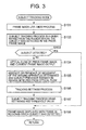
- the CPU 16 detects an instruction to start the imaging mode through a predetermined operation of the function key 4 or the cursor key 5, the CPU 16 reads and executes programs relating to the subject tracking mode from the program memory 14 as shown in the flowchart in FIG. 3 .
- the imaging unit 8 outputs the analog imaging signal corresponding to the optical image of the whole angle of view to the unit circuit 9 with a predetermined period. Furthermore, the unit circuit 9 converts the input analog imaging signal into a digital signal.
- the CPU 16 creates image data on the image processor 10 from that digital signal. Furthermore, the CPU 16 displays the created image data on the display unit 6 as live-view (step S101).
- the aforementioned predetermined period is called a frame
- the image created at this point in time is called the current frame image
- the image created one frame prior to the current frame image is called the prior frame image.
- the subject tracking process includes a process that detects image regions that resemble a template image of the subject detected from the prior frame image above a predetermined threshold value, within a certain range of the region in the current frame image where the prior subject was detected. Furthermore, the subject tracking process includes a process that determines when the subject has moved within that detected image region. Detection of the subject conducted initially is accomplished with respect to the entire region of the frame image (the whole angle of view).
- the subject is the target of imaging, and is a person, a specific part of a person (face, etc.), an animal, an object, etc.
- the CPU 16 determines whether or not the subject has been detected within a given range from the region where the prior subject was detected in step S102 (step S103).
- step S103 When the CPU 16 determines in step S103 that the subject has been detected (step S103; Y), the CPU 16 advances to step S108. On the other hand, when the CPU 16 determines that the subject has not been detected (step S103; N), the CPU 16 partitions the prior frame image into a plurality of blocks. Next, the CPU 16 outputs optical flow indicating the distribution scene of the frame image as a whole in the flow (flow direction) of the movement vector in each of these blocks (step S104).
- the CPU 16 determines the absence or presence of the movement (change in the angle of view) of the imaging apparatus 1 on the basis of the optical flow output in step S104, and detects the subject presence estimation region (the region where it is estimated that there is a high probability that the subject exists) on the basis of the determination results (step S105). Specifically, the CPU 16 detects the change in the angle of view from movement of the background and the four corners of the image in the current frame image on the basis of the optical flow output in step S104. Furthermore, the CPU 16 determines the change in the detected angle of view as being caused by movement of the imaging apparatus. Furthermore, the CPU 16 detects as the subject presence estimation region a region having a flow in a direction differing from the flow accompanying the detected movement of the imaging apparatus 1 in the current frame image.
- FIG. 4 is a flowchart showing the concrete actions of steps S105 and S106.
- the CPU 16 determines whether or not the imaging apparatus 1 has moved on the basis of having detected the change in the angle of view (step S201).
- step S201 When it is determined by the CPU 16 that the imaging apparatus 1 has not moved (step S201; No), in other words when the flow of the background and the four corners of the image in the current frame image are not detected, the CPU 16 then determines whether or not the subject presence estimation region was detected (step S202).
- step S202 When the subject presence estimation region was not detected (step S202; No), that is to say when it is determined that a region having a flow corresponding to the subject presence estimation region does not exist in the current frame image, the CPU 16 reads the normal tracking setting contents (step S203) and the tracking setting process ends.
- the detection range is the range where matching is accomplished using the template image.
- This detection range is a region within a predetermined range from the region where the subject region was detected in the prior frame image.
- the detection threshold value is a threshold value for determining matching to the template image, and image regions with a degree of matching higher than this value are detected as subject regions.
- step S201 when it is determined that the imaging apparatus 1 has moved (step S201; Yes), the CPU 16 determines whether or not a region has been detected in which there is no flow accompanying movement of the imaging apparatus 1 from within the current frame image, and when this is detected judges this to be the subject presence estimation region (step S205).
- step S205 determines that a subject presence estimation region has been detected (step S205; Yes)
- the CPU 16 determines whether or not that subject presence estimation region has no flow in the subsequent frame images (step S206).
- step S206 when the CPU 16 determines that the subject presence estimation region has no flow in the subsequent frame images (step S206; Yes), the detection range is expanded, a tracking setting making the detection threshold value normal is accomplished (step S207) and the tracking setting process ends.
- step S206 when the CPU 16 determines that the subject presence estimation region has flow in the subsequent frame images (step S206; No), the detection range is expanded, tracking setting is accomplished by lowering the detection threshold value (step S204) and the tracking setting process ends.
- step S208 the normal tracking setting contents are read (step S208) and the tracking setting process ends.
- FIG. 5 shows a concrete example of a captured image.
- FIG. 5A shows the prior frame image.
- FIGS. 5B-5F show current frame images.
- FIG. 6A-6E are drawings showing concrete examples of optical flow output when FIG. 5A changes to FIGS. 5B-5F .
- FIG. 7 is a summary of each imaging scene and tracking setting corresponding to the output optical flows.
- step S201, No; Step S202, No the imaging apparatus 1 has captured a stationary subject in a fixed state as indicated by the second row in FIG. 7 . Accordingly, the CPU 16 reads and sets the normal tracking setting contents (step S203).
- the output optical flow is as shown in FIG. 6B and the determination is that the imaging apparatus 1 is not moving.
- this region is determined to be a region in which flow is present, that is to say a subject presence estimation region (step S201, No; step S202, Yes).
- the CPU 16 expands the detection region in order to make detection of the subject easier and accomplishes tracking setting lowering the threshold value (step S204).
- the output optical flow is as shown in FIG. 6C .
- the imaging apparatus 1 is moving but a region with no flow accompanying movement of the imaging apparatus 1 is detected and this region is judged to be a subject presence estimation region (step S201, Yes; step S205, Yes; step S206, Yes).
- this is a scene in which imaging is accomplished following a subject moving in a fixed direction such as panning, as shown in the fourth row of FIG. 7 .
- the CPU 16 accomplishes tracking setting to expand the detection region with the normal threshold value (step S207).
- the output optical flow is as shown in FIG. 6D . That is to say, the imaging apparatus 1 is moving and it is determined that no subject presence estimation region exists (step S201, Yes; step S205, No). In this case, it is considered that this is in a scene in which the imaging apparatus 1 is capturing an image while moving with no subject present, as shown in fifth row of FIG. 7 . Accordingly, the CPU 16 reads and sets the normal tracking setting contents (step S208).
- the output optical flow is as shown in FIG. 6E .
- this region is judged to be a subject presence estimation region (step S201, Yes; step S205, Yes; step S206, No).
- this is a scene in which an irregularly moving subject has not been detected, as shown in sixth row of FIG. 7 .
- the CPU 16 expands the detection range in order to make detection of the subject easier and accomplishes tracking setting by lowering the threshold value (step S204).
- the detection range may be broader than the settings for the cases of FIGS. 5C and 5D in order to make detection of the subject even easier.
- the CPU 16 returns to FIG. 3 and accomplishes the subject tracking process with the set detection range and detection threshold value (step S 107).
- step S108 the CPU 16 sets as the focus region the subject region detected in step S103 or step S107. Furthermore, the CPU 16 accomplishes an imaging preprocess including an auto focus (AF) process, an auto exposure (AE) process and an auto white balance (AWB) process on the set region. Next, the CPU 16 adds a frame to the detected subject region and makes a live-view display of the frame image on the display unit 6. In addition, the image of the detected subject region is updated as the new template image and the above actions are repeated. By repeating in this manner, the CPU 16 successively detects (tracks) to what position the subject is moving for the various frame images successively captured.
- AF auto focus
- AE auto exposure
- AVB auto white balance
- the imaging apparatus 1 it is possible to accomplish subject tracking processes suitable for the imaging scenes by detecting changes in the subject and/or angle of view in the captured image.
- the CPU 16 may determine as the subject presence estimation region a region within the region in which the subject was detected in the prior frame image or a region close to that region.
- the CPU 16 may lower the detection threshold value in the subject presence estimation region detected in step S105 and then accomplish the subject tracking process again.
- the above-described optical flow may be output by the CPU 16 taking into consideration movement vectors originating from camera-shakes. That is to say, the CPU 16 may detect movement of the imaging apparatus on the basis of optical flow output by subtracting movement vectors originating from camera-shakes detected by the camera-shake detector 17 from the output optical flow.
- the program executed by the CPU 16 in the imaging apparatus 1 was explained as prerecorded in the program memory 14, but this may be acquired from an external storage medium or may be one stored after being transmitted over a network.
Abstract
Description
- This application relates generally to an imaging apparatus, a subject tracking method and a storage medium on which programs are recorded.
- Imaging apparatuses equipped with a function that successively detects the position of a moving subject have been known from before. For example, there is technology that tracks a subject using template matching (also called block matching). For example, the image monitoring apparatus disclosed in Patent Literature 1 (Unexamined Japanese Patent Application KOKAI Publication No.
2001-076156 - However, the image monitoring apparatus disclosed in Patent Literature 1 accomplishes block matching using the same search conditions regardless of the behavior of the subject. Consequently, the art disclosed in Patent Literature 1 has the problem that, for example, block matching suitable for the behavior of the subject in the frame image cannot be accomplished.
- Specifically, in this art there is a problem of unnecessary calculation amounts increasing when there is a wide angle of view such as in wide-angle imaging, and when there is virtually no movement of the subject. In addition, in this art when there are narrow angle of views such as in telephoto imaging while movement of the subject is severe, there is a high likelihood that the subject will deviate from the search range, creating the problem that the subject cannot be tracked.
- The present invention addresses the above problem and seeks to attain an imaging apparatus, a subject tracking method and a storage program that can accomplish subject tracking suited to the subject's behavior without being influenced by the angle of view.
In order to solve the above problem, a configuration of the present invention is characterized by being provided with an imaging unit (8), a determination unit (16) that determines an imaging scene on the basis of change between images successively captured by the imaging unit, and a control unit (16)that controls tracking of a subject region contained in the image captured by the imaging unit on the basis of the determination results from the determination unit.
In order to solve the above problem, a configuration of the present invention is a subject tracking method characterized by comprising an imaging step in which images are successively captured in the imaging unit, a determination step that determines an imaging scene on the basis of change between images successively captured in the imaging step, and a control step that controls tracking of a subject region contained in the captured image on the basis of determination results from that determination step.
With the present invention, it is possible to track a subject more ideally than in the past on the basis of the imaging scene. - A more complete understanding of this application can be obtained when the following detailed description is considered in conjunction with the following drawings, in which:
-
FIG. 1A is a front view showing one example of the outside of an imaging apparatus 1 according to the present invention; -
FIG. 1B is a rear view showing one example of the outside of an imaging apparatus 1 according to the present invention; -
FIG. 2 is a block diagram showing one example of the schematic composition of the imaging apparatus 1; -
FIG. 3 is a flowchart showing one example of the operation of the imaging apparatus 1; -
FIG. 4 is a flowchart showing one example of the process for detecting optical flow executed by the imaging apparatus 1; -
FIG. 5A is a figure showing one example of the prior image captured by the imaging apparatus 1; -
FIGS. 5B-F are figures showing examples of current frame image captured by the imaging apparatus 1; -
FIGS. 6A-E are figures showing examples of the optical flow the imaging apparatus 1 detects from the captured image; and -
FIG. 7 is a table showing one example of the scene when the imaging apparatus 1 captures the image. - The imaging apparatus according to the preferred embodiment of the present invention will be described hereafter with reference to the drawings.
FIG. 1A is a front view of the outside of an imaging apparatus 1 according to this embodiment, andFIG. 1B is a rear view. The imaging apparatus 1 is provided on the front with animaging lens 2 and on the top with ashutter key 3. Thisshutter key 3 is equipped with a so-called half-shutter function enabling it to be halfway depressed or fully depressed. In addition, the imaging apparatus 1 is provided on the back surface with afunction key 4, acursor key 5 and adisplay unit 6. Thecursor key 5 functions as a rotary switch rotatable in direction "a" inFIG. 1B .Display unit 6 is composed of an LCD (liquid crystal display) with a 16:9 aspect ratio, for example. -
FIG. 2 is a block diagram showing the schematic composition of the imaging apparatus 1. The imaging apparatus 1 is composed of theimaging lens 2, the key input units 3-5, thedisplay unit 6, adrive controller 7, animaging unit 8, aunit circuit 9, animage processor 10, an encoding/decoding processor 11, apreview engine 12, animage storage unit 13, aprogram memory 14, RAM (random access memory) 15, aCPU 16, a camera-shake detector 17 and abus line 18. - The
CPU 16 is a one-chip microcomputer that controls the various components of the imaging apparatus 1. The imaging apparatus 1 according to this embodiment detects the subject from inside the image captured by the imaging apparatus 1 and tracks that subject. TheCPU 16 controls the various components of the imaging apparatus 1 in order to execute that action. - The
imaging lens 2 is a lens unit composed of a plurality of lenses on which are mounted optical system members provided with a zoom lens, a focus lens, etc. TheCPU 16, upon detecting the photographer's zoom operation or the photographer's half-pressing of theshutter key 3, accomplishes an auto focus (AF) process and sends control signals to thedrive controller 7 to control thedrive controller 7. Thedrive controller 7 causes the position of theimaging lens 2 to move on the basis of those drive signals. - The key input units 3-5 send to the
CPU 16 operation signals in accordance with operation of theshutter key 3, thefunction key 4 and thecursor key 5. - The
imaging unit 8 is composed of an imaging sensor such as a CMOS (complementary metal oxide semiconductor) and is positioned on the optical axis of the above-describedimaging lens 2. - The
unit circuit 9 is a circuit into which an analog imaging signal is input corresponding to the optical image of the subject output from theimaging unit 8. The unit circuit is composed of an automatic gain control (AGC) amplifier that amplifies the imaging signal accompanying the automatic exposure (AE) process and correlated double sampling (CDS) that preserves the input imaging signal. Furthermore, theunit circuit 9 is composed of an analog/digital converter (ADC) that converts the amplified imaging signals into digital imaging signals. Theimage processor 10 performs various types of image processing on the imaging signals sent from theunit circuit 9. - The imaging signal output from the
imaging unit 8 is sent to theimage processor 10 as a digital signal after passing through theunit circuit 9. That digital signal (imaging signal) undergoes various types of image processing in theimage processor 10. Moreover, the digital signal (imaging signal) on which various types of image processing have been performed is compressed in thepreview engine 12 and supplied to thedisplay unit 6. Furthermore, when the supplied digital signal (imaging signal) and the drive control signal that drives the driver built into thedisplay unit 6 are input into thedisplay unit 6, thedisplay unit 6 gives a live-view display of the image based on the digital signal (imaging signal). - An image file is recorded in the
image storage unit 13. Theimage storage unit 13 may be a memory built into the imaging apparatus 1 or may be a removable memory. When recording images, imaging signals processed by theimage processor 10 are compressed and encoded by the encoding/decoding processor 11, made into files using a predetermined file format such as JPEG, and recorded on theimage storage unit 13. On the other hand, image files read from theimage storage unit 13 when playing back images are decoded by the encoding/decoding processor 11 and displayed on thedisplay unit 6. - The
preview engine 12 creates images for the above-described preview display. In addition, thepreview engine 12 accomplishes the necessary control when an image is displayed on thedisplay unit 6 immediately prior to being recorded on theimage storage unit 13 at the time of image recording. - The programs for executing processes shown in the later-described flowcharts are stored in the
program memory 14. TheRAM 15 temporarily stores continuously captured images. The camera-shake detector 17 detects vibrations caused by shaking of the photographer's hands and sends the detected results to theCPU 16. Thebus line 18 connects the various components of the imaging apparatus 1 and transmits data back and forth between these components. - The actions of the imaging apparatus 1 will be described hereafter. When the
CPU 16 detects an instruction to start the imaging mode through a predetermined operation of thefunction key 4 or thecursor key 5, theCPU 16 reads and executes programs relating to the subject tracking mode from theprogram memory 14 as shown in the flowchart inFIG. 3 . - In subject tracking mode, first the
imaging unit 8 outputs the analog imaging signal corresponding to the optical image of the whole angle of view to theunit circuit 9 with a predetermined period. Furthermore, theunit circuit 9 converts the input analog imaging signal into a digital signal. TheCPU 16 creates image data on theimage processor 10 from that digital signal. Furthermore, theCPU 16 displays the created image data on thedisplay unit 6 as live-view (step S101). In the explanation below, the aforementioned predetermined period is called a frame, the image created at this point in time is called the current frame image and the image created one frame prior to the current frame image is called the prior frame image. - When the live-view begins, the
CPU 16 executes a subject tracking process (step S102). The subject tracking process includes a process that detects image regions that resemble a template image of the subject detected from the prior frame image above a predetermined threshold value, within a certain range of the region in the current frame image where the prior subject was detected. Furthermore, the subject tracking process includes a process that determines when the subject has moved within that detected image region. Detection of the subject conducted initially is accomplished with respect to the entire region of the frame image (the whole angle of view). Here, the subject is the target of imaging, and is a person, a specific part of a person (face, etc.), an animal, an object, etc. - Next, the
CPU 16 determines whether or not the subject has been detected within a given range from the region where the prior subject was detected in step S102 (step S103). - When the
CPU 16 determines in step S103 that the subject has been detected (step S103; Y), theCPU 16 advances to step S108. On the other hand, when theCPU 16 determines that the subject has not been detected (step S103; N), theCPU 16 partitions the prior frame image into a plurality of blocks. Next, theCPU 16 outputs optical flow indicating the distribution scene of the frame image as a whole in the flow (flow direction) of the movement vector in each of these blocks (step S104). - The
CPU 16 determines the absence or presence of the movement (change in the angle of view) of the imaging apparatus 1 on the basis of the optical flow output in step S104, and detects the subject presence estimation region (the region where it is estimated that there is a high probability that the subject exists) on the basis of the determination results (step S105). Specifically, theCPU 16 detects the change in the angle of view from movement of the background and the four corners of the image in the current frame image on the basis of the optical flow output in step S104. Furthermore, theCPU 16 determines the change in the detected angle of view as being caused by movement of the imaging apparatus. Furthermore, theCPU 16 detects as the subject presence estimation region a region having a flow in a direction differing from the flow accompanying the detected movement of the imaging apparatus 1 in the current frame image. -
FIG. 4 is a flowchart showing the concrete actions of steps S105 and S106. First, theCPU 16 determines whether or not the imaging apparatus 1 has moved on the basis of having detected the change in the angle of view (step S201). - When it is determined by the
CPU 16 that the imaging apparatus 1 has not moved (step S201; No), in other words when the flow of the background and the four corners of the image in the current frame image are not detected, theCPU 16 then determines whether or not the subject presence estimation region was detected (step S202). When the subject presence estimation region was not detected (step S202; No), that is to say when it is determined that a region having a flow corresponding to the subject presence estimation region does not exist in the current frame image, theCPU 16 reads the normal tracking setting contents (step S203) and the tracking setting process ends. - In addition, when the subject presence estimation region was detected (step S202; Yes), in other words, when it is determined that a region exists in the current frame image having a flow corresponding to the subject presence estimation region, the detection range is expanded more than the above-described normal tracking setting contents and tracking setting is accomplished by lowering the detection threshold value (step S204) and the tracking setting process ends. The detection range is the range where matching is accomplished using the template image. This detection range is a region within a predetermined range from the region where the subject region was detected in the prior frame image. In addition, the detection threshold value is a threshold value for determining matching to the template image, and image regions with a degree of matching higher than this value are detected as subject regions. These setting values are predetermined values set in advance and are stored in a predetermined region of the
program memory 14. - On the other hand, when it is determined that the imaging apparatus 1 has moved (step S201; Yes), the
CPU 16 determines whether or not a region has been detected in which there is no flow accompanying movement of the imaging apparatus 1 from within the current frame image, and when this is detected judges this to be the subject presence estimation region (step S205). - When the
CPU 16 determines that a subject presence estimation region has been detected (step S205; Yes), theCPU 16 then determines whether or not that subject presence estimation region has no flow in the subsequent frame images (step S206). - Furthermore, when the
CPU 16 determines that the subject presence estimation region has no flow in the subsequent frame images (step S206; Yes), the detection range is expanded, a tracking setting making the detection threshold value normal is accomplished (step S207) and the tracking setting process ends. - On the other hand, when the
CPU 16 determines that the subject presence estimation region has flow in the subsequent frame images (step S206; No), the detection range is expanded, tracking setting is accomplished by lowering the detection threshold value (step S204) and the tracking setting process ends. - In addition, when the
CPU 16 determines that a subject presence estimation region has not been detected (step S205; No), the normal tracking setting contents are read (step S208) and the tracking setting process ends. -
FIG. 5 shows a concrete example of a captured image.FIG. 5A shows the prior frame image.FIGS. 5B-5F show current frame images. In addition,FIG. 6A-6E are drawings showing concrete examples of optical flow output whenFIG. 5A changes toFIGS. 5B-5F . In addition,FIG. 7 is a summary of each imaging scene and tracking setting corresponding to the output optical flows. - When the image changes from
FIG. 5A to FIG. 5B , there is no movement in the positions of the subject 51 and the tree (background) 52. Hence, the optical flow output is as shown inFIG. 6A . In other words, there is no movement in the imaging apparatus 1, and there is no subject presence estimation region (step S201, No; Step S202, No). In this case, it is considered that the imaging apparatus 1 has captured a stationary subject in a fixed state as indicated by the second row inFIG. 7 . Accordingly, theCPU 16 reads and sets the normal tracking setting contents (step S203). - When the image changes from
FIG. 5A to FIG. 5C , the subject 51 has moved but position of the tree (background) 52 has not changed. Hence, the output optical flow is as shown inFIG. 6B and the determination is that the imaging apparatus 1 is not moving. In addition, because there is a region inFIG. 6B in which arrows are present, this region is determined to be a region in which flow is present, that is to say a subject presence estimation region (step S201, No; step S202, Yes). In this case, it is considered that this is a scene in which the imaging apparatus 1 has captured a moving subject in a fixed state as indicated by the third row inFIG. 7 . Accordingly, theCPU 16 expands the detection region in order to make detection of the subject easier and accomplishes tracking setting lowering the threshold value (step S204). - When the image changes from
FIG. 5A to FIG. 5D , there is no movement in the position of the subject 51 but the position of the tree (background) 52 has moved. Accordingly, the output optical flow is as shown inFIG. 6C . In this case, the imaging apparatus 1 is moving but a region with no flow accompanying movement of the imaging apparatus 1 is detected and this region is judged to be a subject presence estimation region (step S201, Yes; step S205, Yes; step S206, Yes). In this case, it is considered that this is a scene in which imaging is accomplished following a subject moving in a fixed direction such as panning, as shown in the fourth row ofFIG. 7 . Although the direction of the subject in the angle of view does not change in this imaging scene, it is considered that there is a possibility that the position of the subject could shift. Accordingly, theCPU 16 accomplishes tracking setting to expand the detection region with the normal threshold value (step S207). - When the image changes from
FIG. 5A to FIG. 5E , the positions of the subject 51 and the tree (background) 52 are moving in the same direction. Hence, the output optical flow is as shown inFIG. 6D . That is to say, the imaging apparatus 1 is moving and it is determined that no subject presence estimation region exists (step S201, Yes; step S205, No). In this case, it is considered that this is in a scene in which the imaging apparatus 1 is capturing an image while moving with no subject present, as shown in fifth row ofFIG. 7 . Accordingly, theCPU 16 reads and sets the normal tracking setting contents (step S208). - When the image changes from
FIG. 5A to FIG. 5F , the subject 51 and the tree (background) 52 are each moving in different directions. Hence, the output optical flow is as shown inFIG. 6E . In this case, because there is flow in a different direction (the region with different arrow direction from the surroundings inFIG. 6E ) from the flow corresponding to the detected motion of the imaging apparatus 1, this region is judged to be a subject presence estimation region (step S201, Yes; step S205, Yes; step S206, No). In this case, it is considered that this is a scene in which an irregularly moving subject has not been detected, as shown in sixth row ofFIG. 7 . Accordingly, theCPU 16 expands the detection range in order to make detection of the subject easier and accomplishes tracking setting by lowering the threshold value (step S204). In this case, the detection range may be broader than the settings for the cases ofFIGS. 5C and 5D in order to make detection of the subject even easier. - With the above-described settings, it is possible to detect and track the subject suitably.
- When the tracking setting process ends, the
CPU 16 returns toFIG. 3 and accomplishes the subject tracking process with the set detection range and detection threshold value (step S 107). - Furthermore, in step S108 the
CPU 16 sets as the focus region the subject region detected in step S103 or step S107. Furthermore, theCPU 16 accomplishes an imaging preprocess including an auto focus (AF) process, an auto exposure (AE) process and an auto white balance (AWB) process on the set region. Next, theCPU 16 adds a frame to the detected subject region and makes a live-view display of the frame image on thedisplay unit 6. In addition, the image of the detected subject region is updated as the new template image and the above actions are repeated. By repeating in this manner, theCPU 16 successively detects (tracks) to what position the subject is moving for the various frame images successively captured. - With the imaging apparatus 1 according to this embodiment, it is possible to accomplish subject tracking processes suitable for the imaging scenes by detecting changes in the subject and/or angle of view in the captured image.
- The above-described embodiment is intended to be illustrative and not limiting, for various variations and applications are possible.
- For example, when a plurality of regions are detected as subject presence estimation regions in step S105 of
FIG. 3 , theCPU 16 may determine as the subject presence estimation region a region within the region in which the subject was detected in the prior frame image or a region close to that region. - In addition, when the subject cannot be tracked with the subject tracking process in step S107 of
FIG. 3 , theCPU 16 may lower the detection threshold value in the subject presence estimation region detected in step S105 and then accomplish the subject tracking process again. - In addition, the above-described optical flow may be output by the
CPU 16 taking into consideration movement vectors originating from camera-shakes. That is to say, theCPU 16 may detect movement of the imaging apparatus on the basis of optical flow output by subtracting movement vectors originating from camera-shakes detected by the camera-shake detector 17 from the output optical flow. - In addition, the program executed by the
CPU 16 in the imaging apparatus 1 was explained as prerecorded in theprogram memory 14, but this may be acquired from an external storage medium or may be one stored after being transmitted over a network. - Having described and illustrated the principles of this application by reference to one or more preferred embodiments, it should be apparent that the preferred embodiments may be modified in arrangement and detail without departing from the principles disclosed herein and that it is intended that the application be construed as including all such modifications and variations insofar as they come within the spirit and scope of the subject matter disclosed herein.
Claims (12)
- An imaging apparatus characterized by comprising:an imaging unit (8);a determination unit (16) that determines an imaging scene on the basis of change between images successively captured by the imaging unit; anda control unit (16) that controls tracking of a subject region included in the image captured by the imaging unit on the basis of determination results from the determination unit.
- The imaging apparatus according to Claim 1, characterized in that the control unit changes a range where the subject region should be tracked in the image on the basis of the determination results from the determination unit.
- The imaging apparatus according to Claim 1, characterized by further comprising:a specification unit that specifies as the subject region corresponding to a subject that should be tracked an image region matching above a predetermined threshold value a standard image prepared from the image captured by the imaging unit in advance;wherein the control unit includes a changing unit for changing the predetermined threshold value on the basis of the determination results from the determination unit.
- The imaging apparatus according to Claim 3, characterized in that the control unit changes the predetermined threshold value to a value lower than the threshold value set immediately prior on the basis of the determination results from the determination unit.
- The imaging apparatus according to Claim 1, characterized in that the determination unit includes:a change detection unit (16) that detects change between the images successively captured by the imaging unit; anda subject detection unit (16) that detects as the subject region a region in which there is change differing from the change detected by the change detection unit;wherein the determination unit determines the imaging scene on the basis of detection results from the subject detection unit and detection results from the change detection unit.
- The imaging apparatus according to Claim 5, characterized in that:the determination unit determines a direction of change of an angle of view between the images on the basis of the change between the images detected by the change detection unit; andthe subject detection unit detects as the subject region a region having a direction of change differing from the direction of the change thus determined.
- The imaging apparatus according to Claim 5, characterized in that:the determination unit determines an amount of change in an angle of view between the images on the basis of the change between the images detected by the change detection unit; andthe subject detection unit detects as the subject region a region having an amount of change differing from the amount of the change thus determined.
- The imaging apparatus according to Claim 5, characterized in that the subject detection unit determines whether or not a plurality of regions have been detected as subject regions, and when a plurality of regions have been detected, detects as the subject region that should be tracked a subject region detected in the region closest to the most recently tracked subject region out of that plurality of regions.
- The imaging apparatus according to Claim 5, characterized by further comprising:an output unit that outputs a vector distribution of movement vectors between the images successively captured by the imaging unit;wherein the change detection unit detects the change between the images on the basis of the vector distribution output by the output unit; and
the subject detection unit detects the subject region on the basis of the change between images detected by the change detection unit and the vector distribution output by the output unit. - The imaging apparatus according to Claim 9, characterized in that the output unit outputs the vector distribution by subtracting movement vectors caused by camera-shakes from the movement vector between the successively captured images.
- A subject tracking method characterized by comprising:an imaging step that successively captures images in an imaging unit;a determination step that determines an imaging scene on the basis of change between the images successively captured in the imaging step; anda control step that controls tracking of a subject region contained in the captured image on the basis of determination results from the determination step.
- A storage medium storing a program causing an imaging apparatus' computer to function as:a determination unit that determines an imaging scene on the basis of change between successively captured images; anda control unit that controls tracking of a subject region contained in the image captured by an imaging unit on the basis of determination results from the determination unit.
Applications Claiming Priority (1)
| Application Number | Priority Date | Filing Date | Title |
|---|---|---|---|
| JP2009013439A JP4760918B2 (en) | 2009-01-23 | 2009-01-23 | Imaging apparatus, subject tracking method, and program |
Publications (2)
| Publication Number | Publication Date |
|---|---|
| EP2211306A1 true EP2211306A1 (en) | 2010-07-28 |
| EP2211306B1 EP2211306B1 (en) | 2017-07-26 |
Family
ID=42097182
Family Applications (1)
| Application Number | Title | Priority Date | Filing Date |
|---|---|---|---|
| EP10151353.9A Not-in-force EP2211306B1 (en) | 2009-01-23 | 2010-01-22 | Imaging apparatus, subject tracking method and storage medium |
Country Status (6)
| Country | Link |
|---|---|
| US (1) | US20100188511A1 (en) |
| EP (1) | EP2211306B1 (en) |
| JP (1) | JP4760918B2 (en) |
| KR (2) | KR20100086943A (en) |
| CN (1) | CN101867725B (en) |
| TW (1) | TWI419552B (en) |
Families Citing this family (26)
| Publication number | Priority date | Publication date | Assignee | Title |
|---|---|---|---|---|
| US9030536B2 (en) | 2010-06-04 | 2015-05-12 | At&T Intellectual Property I, Lp | Apparatus and method for presenting media content |
| US9787974B2 (en) | 2010-06-30 | 2017-10-10 | At&T Intellectual Property I, L.P. | Method and apparatus for delivering media content |
| US8918831B2 (en) | 2010-07-06 | 2014-12-23 | At&T Intellectual Property I, Lp | Method and apparatus for managing a presentation of media content |
| US9049426B2 (en) | 2010-07-07 | 2015-06-02 | At&T Intellectual Property I, Lp | Apparatus and method for distributing three dimensional media content |
| US9232274B2 (en) | 2010-07-20 | 2016-01-05 | At&T Intellectual Property I, L.P. | Apparatus for adapting a presentation of media content to a requesting device |
| US9032470B2 (en) | 2010-07-20 | 2015-05-12 | At&T Intellectual Property I, Lp | Apparatus for adapting a presentation of media content according to a position of a viewing apparatus |
| US9560406B2 (en) | 2010-07-20 | 2017-01-31 | At&T Intellectual Property I, L.P. | Method and apparatus for adapting a presentation of media content |
| US8994716B2 (en) | 2010-08-02 | 2015-03-31 | At&T Intellectual Property I, Lp | Apparatus and method for providing media content |
| US8438502B2 (en) | 2010-08-25 | 2013-05-07 | At&T Intellectual Property I, L.P. | Apparatus for controlling three-dimensional images |
| US8947511B2 (en) | 2010-10-01 | 2015-02-03 | At&T Intellectual Property I, L.P. | Apparatus and method for presenting three-dimensional media content |
| US9007429B2 (en) * | 2011-04-06 | 2015-04-14 | Casio Computer Co., Ltd. | Image processing device capable of generating wide-range image |
| KR101223528B1 (en) * | 2011-04-25 | 2013-01-21 | 한국과학기술원 | Method for operating surveillance camera system in cooperative ways, system and camera for the same |
| JP6071173B2 (en) * | 2011-05-23 | 2017-02-01 | キヤノン株式会社 | Imaging apparatus, control method thereof, and program |
| US8947497B2 (en) | 2011-06-24 | 2015-02-03 | At&T Intellectual Property I, Lp | Apparatus and method for managing telepresence sessions |
| US9602766B2 (en) | 2011-06-24 | 2017-03-21 | At&T Intellectual Property I, L.P. | Apparatus and method for presenting three dimensional objects with telepresence |
| JP5800600B2 (en) * | 2011-06-24 | 2015-10-28 | オリンパス株式会社 | Imaging apparatus, imaging method, and program |
| US9445046B2 (en) | 2011-06-24 | 2016-09-13 | At&T Intellectual Property I, L.P. | Apparatus and method for presenting media content with telepresence |
| US9030522B2 (en) | 2011-06-24 | 2015-05-12 | At&T Intellectual Property I, Lp | Apparatus and method for providing media content |
| US8587635B2 (en) | 2011-07-15 | 2013-11-19 | At&T Intellectual Property I, L.P. | Apparatus and method for providing media services with telepresence |
| JP5945425B2 (en) * | 2012-02-02 | 2016-07-05 | オリンパス株式会社 | Imaging apparatus and imaging method thereof |
| JP6181925B2 (en) * | 2012-12-12 | 2017-08-16 | キヤノン株式会社 | Image processing apparatus, image processing apparatus control method, and program |
| US9154686B2 (en) * | 2013-09-25 | 2015-10-06 | Google Technology Holdings LLC | Close focus with GPU |
| JP6493746B2 (en) * | 2015-04-08 | 2019-04-03 | リコーイメージング株式会社 | Image tracking device and image tracking method |
| JP6587006B2 (en) * | 2018-03-14 | 2019-10-09 | エスゼット ディージェイアイ テクノロジー カンパニー リミテッドSz Dji Technology Co.,Ltd | Moving body detection device, control device, moving body, moving body detection method, and program |
| TWI697914B (en) * | 2018-11-29 | 2020-07-01 | 宏碁股份有限公司 | Monitoring device and method thereof |
| CN115278043A (en) * | 2021-04-30 | 2022-11-01 | 华为技术有限公司 | Target tracking method and related device |
Citations (6)
| Publication number | Priority date | Publication date | Assignee | Title |
|---|---|---|---|---|
| JP2001076156A (en) | 1999-09-03 | 2001-03-23 | Mitsubishi Electric Corp | Device for monitoring image |
| US20030035051A1 (en) | 2001-08-07 | 2003-02-20 | Samsung Electronics Co., Ltd. | Device for and method of automatically tracking a moving object |
| US20040125984A1 (en) | 2002-12-19 | 2004-07-01 | Wataru Ito | Object tracking method and object tracking apparatus |
| US20060088191A1 (en) | 2004-10-25 | 2006-04-27 | Tong Zhang | Video content understanding through real time video motion analysis |
| US20080037869A1 (en) | 2006-07-13 | 2008-02-14 | Hui Zhou | Method and Apparatus for Determining Motion in Images |
| EP1988505A1 (en) | 2007-05-03 | 2008-11-05 | Sony Deutschland Gmbh | Method and system for initializing templates of moving objects |
Family Cites Families (16)
| Publication number | Priority date | Publication date | Assignee | Title |
|---|---|---|---|---|
| JP2956056B2 (en) * | 1988-10-27 | 1999-10-04 | キヤノン株式会社 | Tracking control method and apparatus, and shake correction method and apparatus |
| JPH03149512A (en) * | 1989-11-07 | 1991-06-26 | Sony Corp | Focus control circuit |
| JP2698827B2 (en) * | 1993-11-05 | 1998-01-19 | カシオ計算機株式会社 | Method of manufacturing semiconductor device having bump electrode |
| JP3268953B2 (en) * | 1995-02-27 | 2002-03-25 | 三洋電機株式会社 | Tracking area setting device, motion vector detection circuit, and subject tracking device using the same |
| MXPA03011520A (en) * | 2002-04-17 | 2004-03-18 | Matsushita Electric Ind Co Ltd | Motion detector, image processing system, motion detecting method, program, and recording medium. |
| US7385626B2 (en) * | 2002-10-21 | 2008-06-10 | Sarnoff Corporation | Method and system for performing surveillance |
| US7660439B1 (en) * | 2003-12-16 | 2010-02-09 | Verificon Corporation | Method and system for flow detection and motion analysis |
| WO2005066897A1 (en) * | 2004-01-06 | 2005-07-21 | Sony Corporation | Image processing device and method, recording medium, and program |
| CN101393642B (en) * | 2004-01-06 | 2011-05-18 | 索尼株式会社 | Image processing device and method |
| CN101398890B (en) * | 2004-08-03 | 2010-12-08 | 松下电器产业株式会社 | Human identification apparatus |
| WO2006121088A1 (en) * | 2005-05-10 | 2006-11-16 | Olympus Corporation | Image processing device, image processing method, and image processing program |
| JP4241742B2 (en) * | 2006-01-31 | 2009-03-18 | パナソニック株式会社 | Automatic tracking device and automatic tracking method |
| JP4025362B2 (en) * | 2006-02-15 | 2007-12-19 | 松下電器産業株式会社 | Imaging apparatus and imaging method |
| JP4961850B2 (en) * | 2006-06-15 | 2012-06-27 | ソニー株式会社 | Motion detection method, motion detection method program, recording medium recording motion detection method program, and motion detection apparatus |
| JP4935380B2 (en) * | 2007-01-29 | 2012-05-23 | 株式会社ニコン | Image tracking device and imaging device |
| JP4315215B2 (en) * | 2007-05-18 | 2009-08-19 | カシオ計算機株式会社 | Imaging apparatus, face detection method, and face detection control program |
-
2009
- 2009-01-23 JP JP2009013439A patent/JP4760918B2/en not_active Expired - Fee Related
-
2010
- 2010-01-19 KR KR1020100004682A patent/KR20100086943A/en active Application Filing
- 2010-01-20 US US12/690,209 patent/US20100188511A1/en not_active Abandoned
- 2010-01-21 CN CN2010101753166A patent/CN101867725B/en not_active Expired - Fee Related
- 2010-01-22 TW TW099101709A patent/TWI419552B/en not_active IP Right Cessation
- 2010-01-22 EP EP10151353.9A patent/EP2211306B1/en not_active Not-in-force
-
2012
- 2012-08-24 KR KR1020120092860A patent/KR101290611B1/en active IP Right Grant
Patent Citations (6)
| Publication number | Priority date | Publication date | Assignee | Title |
|---|---|---|---|---|
| JP2001076156A (en) | 1999-09-03 | 2001-03-23 | Mitsubishi Electric Corp | Device for monitoring image |
| US20030035051A1 (en) | 2001-08-07 | 2003-02-20 | Samsung Electronics Co., Ltd. | Device for and method of automatically tracking a moving object |
| US20040125984A1 (en) | 2002-12-19 | 2004-07-01 | Wataru Ito | Object tracking method and object tracking apparatus |
| US20060088191A1 (en) | 2004-10-25 | 2006-04-27 | Tong Zhang | Video content understanding through real time video motion analysis |
| US20080037869A1 (en) | 2006-07-13 | 2008-02-14 | Hui Zhou | Method and Apparatus for Determining Motion in Images |
| EP1988505A1 (en) | 2007-05-03 | 2008-11-05 | Sony Deutschland Gmbh | Method and system for initializing templates of moving objects |
Also Published As
| Publication number | Publication date |
|---|---|
| CN101867725B (en) | 2013-06-05 |
| EP2211306B1 (en) | 2017-07-26 |
| KR20120114191A (en) | 2012-10-16 |
| CN101867725A (en) | 2010-10-20 |
| TWI419552B (en) | 2013-12-11 |
| TW201032585A (en) | 2010-09-01 |
| KR101290611B1 (en) | 2013-07-29 |
| JP4760918B2 (en) | 2011-08-31 |
| US20100188511A1 (en) | 2010-07-29 |
| JP2010171815A (en) | 2010-08-05 |
| KR20100086943A (en) | 2010-08-02 |
Similar Documents
| Publication | Publication Date | Title |
|---|---|---|
| EP2211306B1 (en) | Imaging apparatus, subject tracking method and storage medium | |
| JP4687404B2 (en) | Image signal processing apparatus, imaging apparatus, and image signal processing method | |
| US8988529B2 (en) | Target tracking apparatus, image tracking apparatus, methods of controlling operation of same, and digital camera | |
| US8149288B2 (en) | Image capture device that records image accordant with predetermined condition and storage medium that stores program | |
| US8131014B2 (en) | Object-tracking computer program product, object-tracking device, and camera | |
| EP2741293A1 (en) | Video processing apparatus and method | |
| US20100165113A1 (en) | Subject tracking computer program product, subject tracking device and camera | |
| CN101800850B (en) | Imaging apparatus, imaging method and storage medium | |
| JP2006317848A (en) | Still picture imaging apparatus | |
| JP2006287920A (en) | Video camera and image extracting apparatus utilized for the same | |
| JP2011040902A (en) | Image capturing apparatus and control apparatus for the same | |
| JP2009225027A (en) | Imaging apparatus, imaging control method, and program | |
| JP2009111716A (en) | Imaging apparatus, program and template generating method | |
| JP4840731B2 (en) | Imaging apparatus, imaging method, and program | |
| JP2009081530A (en) | Imaging apparatus and imaging method | |
| JP4807582B2 (en) | Image processing apparatus, imaging apparatus, and program thereof | |
| JP4888829B2 (en) | Movie processing device, movie shooting device, and movie shooting program | |
| JP2011130378A (en) | Image recording apparatus and image recording method | |
| JP2006145641A (en) | Camera apparatus and focusing-area control program | |
| JP5137808B2 (en) | Imaging device, control method thereof, and program | |
| JP2010266538A (en) | Photographing device | |
| JP5109866B2 (en) | Imaging apparatus, imaging method, and program | |
| JP2007228492A (en) | Image processing apparatus | |
| JP2008219755A (en) | Camera shake determination device and method, program, and imaging apparatus | |
| JP2015012487A (en) | Image processing device and imaging device |
Legal Events
| Date | Code | Title | Description |
|---|---|---|---|
| PUAI | Public reference made under article 153(3) epc to a published international application that has entered the european phase |
Free format text: ORIGINAL CODE: 0009012 |
|
| 17P | Request for examination filed |
Effective date: 20100122 |
|
| AK | Designated contracting states |
Kind code of ref document: A1 Designated state(s): AT BE BG CH CY CZ DE DK EE ES FI FR GB GR HR HU IE IS IT LI LT LU LV MC MK MT NL NO PL PT RO SE SI SK SM TR |
|
| AX | Request for extension of the european patent |
Extension state: AL BA RS |
|
| 17Q | First examination report despatched |
Effective date: 20121203 |
|
| GRAP | Despatch of communication of intention to grant a patent |
Free format text: ORIGINAL CODE: EPIDOSNIGR1 |
|
| INTG | Intention to grant announced |
Effective date: 20170207 |
|
| GRAS | Grant fee paid |
Free format text: ORIGINAL CODE: EPIDOSNIGR3 |
|
| GRAA | (expected) grant |
Free format text: ORIGINAL CODE: 0009210 |
|
| AK | Designated contracting states |
Kind code of ref document: B1 Designated state(s): AT BE BG CH CY CZ DE DK EE ES FI FR GB GR HR HU IE IS IT LI LT LU LV MC MK MT NL NO PL PT RO SE SI SK SM TR |
|
| REG | Reference to a national code |
Ref country code: GB Ref legal event code: FG4D |
|
| REG | Reference to a national code |
Ref country code: CH Ref legal event code: EP |
|
| REG | Reference to a national code |
Ref country code: AT Ref legal event code: REF Ref document number: 912945 Country of ref document: AT Kind code of ref document: T Effective date: 20170815 |
|
| REG | Reference to a national code |
Ref country code: IE Ref legal event code: FG4D |
|
| REG | Reference to a national code |
Ref country code: DE Ref legal event code: R096 Ref document number: 602010043828 Country of ref document: DE |
|
| REG | Reference to a national code |
Ref country code: NL Ref legal event code: MP Effective date: 20170726 |
|
| REG | Reference to a national code |
Ref country code: FR Ref legal event code: PLFP Year of fee payment: 9 Ref country code: LT Ref legal event code: MG4D |
|
| REG | Reference to a national code |
Ref country code: AT Ref legal event code: MK05 Ref document number: 912945 Country of ref document: AT Kind code of ref document: T Effective date: 20170726 |
|
| PG25 | Lapsed in a contracting state [announced via postgrant information from national office to epo] |
Ref country code: SE Free format text: LAPSE BECAUSE OF FAILURE TO SUBMIT A TRANSLATION OF THE DESCRIPTION OR TO PAY THE FEE WITHIN THE PRESCRIBED TIME-LIMIT Effective date: 20170726 Ref country code: FI Free format text: LAPSE BECAUSE OF FAILURE TO SUBMIT A TRANSLATION OF THE DESCRIPTION OR TO PAY THE FEE WITHIN THE PRESCRIBED TIME-LIMIT Effective date: 20170726 Ref country code: AT Free format text: LAPSE BECAUSE OF FAILURE TO SUBMIT A TRANSLATION OF THE DESCRIPTION OR TO PAY THE FEE WITHIN THE PRESCRIBED TIME-LIMIT Effective date: 20170726 Ref country code: NO Free format text: LAPSE BECAUSE OF FAILURE TO SUBMIT A TRANSLATION OF THE DESCRIPTION OR TO PAY THE FEE WITHIN THE PRESCRIBED TIME-LIMIT Effective date: 20171026 Ref country code: HR Free format text: LAPSE BECAUSE OF FAILURE TO SUBMIT A TRANSLATION OF THE DESCRIPTION OR TO PAY THE FEE WITHIN THE PRESCRIBED TIME-LIMIT Effective date: 20170726 Ref country code: LT Free format text: LAPSE BECAUSE OF FAILURE TO SUBMIT A TRANSLATION OF THE DESCRIPTION OR TO PAY THE FEE WITHIN THE PRESCRIBED TIME-LIMIT Effective date: 20170726 Ref country code: NL Free format text: LAPSE BECAUSE OF FAILURE TO SUBMIT A TRANSLATION OF THE DESCRIPTION OR TO PAY THE FEE WITHIN THE PRESCRIBED TIME-LIMIT Effective date: 20170726 |
|
| PG25 | Lapsed in a contracting state [announced via postgrant information from national office to epo] |
Ref country code: LV Free format text: LAPSE BECAUSE OF FAILURE TO SUBMIT A TRANSLATION OF THE DESCRIPTION OR TO PAY THE FEE WITHIN THE PRESCRIBED TIME-LIMIT Effective date: 20170726 Ref country code: IS Free format text: LAPSE BECAUSE OF FAILURE TO SUBMIT A TRANSLATION OF THE DESCRIPTION OR TO PAY THE FEE WITHIN THE PRESCRIBED TIME-LIMIT Effective date: 20171126 Ref country code: BG Free format text: LAPSE BECAUSE OF FAILURE TO SUBMIT A TRANSLATION OF THE DESCRIPTION OR TO PAY THE FEE WITHIN THE PRESCRIBED TIME-LIMIT Effective date: 20171026 Ref country code: GR Free format text: LAPSE BECAUSE OF FAILURE TO SUBMIT A TRANSLATION OF THE DESCRIPTION OR TO PAY THE FEE WITHIN THE PRESCRIBED TIME-LIMIT Effective date: 20171027 Ref country code: ES Free format text: LAPSE BECAUSE OF FAILURE TO SUBMIT A TRANSLATION OF THE DESCRIPTION OR TO PAY THE FEE WITHIN THE PRESCRIBED TIME-LIMIT Effective date: 20170726 Ref country code: PL Free format text: LAPSE BECAUSE OF FAILURE TO SUBMIT A TRANSLATION OF THE DESCRIPTION OR TO PAY THE FEE WITHIN THE PRESCRIBED TIME-LIMIT Effective date: 20170726 |
|
| PG25 | Lapsed in a contracting state [announced via postgrant information from national office to epo] |
Ref country code: CZ Free format text: LAPSE BECAUSE OF FAILURE TO SUBMIT A TRANSLATION OF THE DESCRIPTION OR TO PAY THE FEE WITHIN THE PRESCRIBED TIME-LIMIT Effective date: 20170726 Ref country code: DK Free format text: LAPSE BECAUSE OF FAILURE TO SUBMIT A TRANSLATION OF THE DESCRIPTION OR TO PAY THE FEE WITHIN THE PRESCRIBED TIME-LIMIT Effective date: 20170726 Ref country code: RO Free format text: LAPSE BECAUSE OF FAILURE TO SUBMIT A TRANSLATION OF THE DESCRIPTION OR TO PAY THE FEE WITHIN THE PRESCRIBED TIME-LIMIT Effective date: 20170726 |
|
| REG | Reference to a national code |
Ref country code: DE Ref legal event code: R097 Ref document number: 602010043828 Country of ref document: DE |
|
| PG25 | Lapsed in a contracting state [announced via postgrant information from national office to epo] |
Ref country code: SK Free format text: LAPSE BECAUSE OF FAILURE TO SUBMIT A TRANSLATION OF THE DESCRIPTION OR TO PAY THE FEE WITHIN THE PRESCRIBED TIME-LIMIT Effective date: 20170726 Ref country code: SM Free format text: LAPSE BECAUSE OF FAILURE TO SUBMIT A TRANSLATION OF THE DESCRIPTION OR TO PAY THE FEE WITHIN THE PRESCRIBED TIME-LIMIT Effective date: 20170726 Ref country code: IT Free format text: LAPSE BECAUSE OF FAILURE TO SUBMIT A TRANSLATION OF THE DESCRIPTION OR TO PAY THE FEE WITHIN THE PRESCRIBED TIME-LIMIT Effective date: 20170726 Ref country code: EE Free format text: LAPSE BECAUSE OF FAILURE TO SUBMIT A TRANSLATION OF THE DESCRIPTION OR TO PAY THE FEE WITHIN THE PRESCRIBED TIME-LIMIT Effective date: 20170726 |
|
| PLBE | No opposition filed within time limit |
Free format text: ORIGINAL CODE: 0009261 |
|
| STAA | Information on the status of an ep patent application or granted ep patent |
Free format text: STATUS: NO OPPOSITION FILED WITHIN TIME LIMIT |
|
| 26N | No opposition filed |
Effective date: 20180430 |
|
| PG25 | Lapsed in a contracting state [announced via postgrant information from national office to epo] |
Ref country code: SI Free format text: LAPSE BECAUSE OF FAILURE TO SUBMIT A TRANSLATION OF THE DESCRIPTION OR TO PAY THE FEE WITHIN THE PRESCRIBED TIME-LIMIT Effective date: 20170726 |
|
| REG | Reference to a national code |
Ref country code: CH Ref legal event code: PL |
|
| PG25 | Lapsed in a contracting state [announced via postgrant information from national office to epo] |
Ref country code: LU Free format text: LAPSE BECAUSE OF NON-PAYMENT OF DUE FEES Effective date: 20180122 |
|
| REG | Reference to a national code |
Ref country code: IE Ref legal event code: MM4A |
|
| REG | Reference to a national code |
Ref country code: BE Ref legal event code: MM Effective date: 20180131 |
|
| PG25 | Lapsed in a contracting state [announced via postgrant information from national office to epo] |
Ref country code: LI Free format text: LAPSE BECAUSE OF NON-PAYMENT OF DUE FEES Effective date: 20180131 Ref country code: CH Free format text: LAPSE BECAUSE OF NON-PAYMENT OF DUE FEES Effective date: 20180131 Ref country code: BE Free format text: LAPSE BECAUSE OF NON-PAYMENT OF DUE FEES Effective date: 20180131 |
|
| PG25 | Lapsed in a contracting state [announced via postgrant information from national office to epo] |
Ref country code: IE Free format text: LAPSE BECAUSE OF NON-PAYMENT OF DUE FEES Effective date: 20180122 |
|
| PG25 | Lapsed in a contracting state [announced via postgrant information from national office to epo] |
Ref country code: MC Free format text: LAPSE BECAUSE OF FAILURE TO SUBMIT A TRANSLATION OF THE DESCRIPTION OR TO PAY THE FEE WITHIN THE PRESCRIBED TIME-LIMIT Effective date: 20170726 |
|
| PG25 | Lapsed in a contracting state [announced via postgrant information from national office to epo] |
Ref country code: MT Free format text: LAPSE BECAUSE OF NON-PAYMENT OF DUE FEES Effective date: 20180122 |
|
| PGFP | Annual fee paid to national office [announced via postgrant information from national office to epo] |
Ref country code: FR Payment date: 20191216 Year of fee payment: 11 |
|
| PG25 | Lapsed in a contracting state [announced via postgrant information from national office to epo] |
Ref country code: TR Free format text: LAPSE BECAUSE OF FAILURE TO SUBMIT A TRANSLATION OF THE DESCRIPTION OR TO PAY THE FEE WITHIN THE PRESCRIBED TIME-LIMIT Effective date: 20170726 |
|
| PGFP | Annual fee paid to national office [announced via postgrant information from national office to epo] |
Ref country code: GB Payment date: 20200115 Year of fee payment: 11 |
|
| PG25 | Lapsed in a contracting state [announced via postgrant information from national office to epo] |
Ref country code: HU Free format text: LAPSE BECAUSE OF FAILURE TO SUBMIT A TRANSLATION OF THE DESCRIPTION OR TO PAY THE FEE WITHIN THE PRESCRIBED TIME-LIMIT; INVALID AB INITIO Effective date: 20100122 Ref country code: PT Free format text: LAPSE BECAUSE OF FAILURE TO SUBMIT A TRANSLATION OF THE DESCRIPTION OR TO PAY THE FEE WITHIN THE PRESCRIBED TIME-LIMIT Effective date: 20170726 |
|
| PG25 | Lapsed in a contracting state [announced via postgrant information from national office to epo] |
Ref country code: CY Free format text: LAPSE BECAUSE OF FAILURE TO SUBMIT A TRANSLATION OF THE DESCRIPTION OR TO PAY THE FEE WITHIN THE PRESCRIBED TIME-LIMIT Effective date: 20170726 Ref country code: MK Free format text: LAPSE BECAUSE OF NON-PAYMENT OF DUE FEES Effective date: 20170726 |
|
| GBPC | Gb: european patent ceased through non-payment of renewal fee |
Effective date: 20210122 |
|
| PG25 | Lapsed in a contracting state [announced via postgrant information from national office to epo] |
Ref country code: FR Free format text: LAPSE BECAUSE OF NON-PAYMENT OF DUE FEES Effective date: 20210131 |
|
| PG25 | Lapsed in a contracting state [announced via postgrant information from national office to epo] |
Ref country code: GB Free format text: LAPSE BECAUSE OF NON-PAYMENT OF DUE FEES Effective date: 20210122 |
|
| PGFP | Annual fee paid to national office [announced via postgrant information from national office to epo] |
Ref country code: DE Payment date: 20211130 Year of fee payment: 13 |
|
| REG | Reference to a national code |
Ref country code: DE Ref legal event code: R119 Ref document number: 602010043828 Country of ref document: DE |
|
| PG25 | Lapsed in a contracting state [announced via postgrant information from national office to epo] |
Ref country code: DE Free format text: LAPSE BECAUSE OF NON-PAYMENT OF DUE FEES Effective date: 20230801 |